US5388048A - Vehicle anti-collison device - Google Patents
Vehicle anti-collison deviceDownload PDFInfo
- Publication number
- US5388048A US5388048AUS08/017,742US1774293AUS5388048AUS 5388048 AUS5388048 AUS 5388048AUS 1774293 AUS1774293 AUS 1774293AUS 5388048 AUS5388048 AUS 5388048A
- Authority
- US
- United States
- Prior art keywords
- vehicle
- determination means
- speed
- distance
- self
- Prior art date
- Legal status (The legal status is an assumption and is not a legal conclusion. Google has not performed a legal analysis and makes no representation as to the accuracy of the status listed.)
- Expired - Fee Related
Links
Images


Classifications
- G—PHYSICS
- G01—MEASURING; TESTING
- G01S—RADIO DIRECTION-FINDING; RADIO NAVIGATION; DETERMINING DISTANCE OR VELOCITY BY USE OF RADIO WAVES; LOCATING OR PRESENCE-DETECTING BY USE OF THE REFLECTION OR RERADIATION OF RADIO WAVES; ANALOGOUS ARRANGEMENTS USING OTHER WAVES
- G01S17/00—Systems using the reflection or reradiation of electromagnetic waves other than radio waves, e.g. lidar systems
- G01S17/88—Lidar systems specially adapted for specific applications
- G01S17/93—Lidar systems specially adapted for specific applications for anti-collision purposes
- G01S17/931—Lidar systems specially adapted for specific applications for anti-collision purposes of land vehicles
Definitions
- This inventionrelates to a vehicle anti-collision device for aiding a driver in maintaining a safe distance between his vehicle and the one in front.
- active devicesinclude a servo-control system typically coupled to the throttle valve so that, in the event that the driver does not maintain a safe distance from the leading vehicle for his current road speed, the following vehicle is automatically decelerated so as to reduce its road speed to a safe stopping speed based on the reduced distance between the two vehicles.
- a servo-control systemtypically coupled to the throttle valve so that, in the event that the driver does not maintain a safe distance from the leading vehicle for his current road speed, the following vehicle is automatically decelerated so as to reduce its road speed to a safe stopping speed based on the reduced distance between the two vehicles.
- Yoshino et al.is based on a laser radar for measuring the distance of the following vehicle from the leading vehicle, the speed of the following vehicle being determined by a speed sensor coupled to the speedometer.
- passive systemsalso must comprise at least these two elements: namely some sort of rangefinder for determining the distance between two vehicles and also means for determining the speed of the following vehicle.
- rangefinderfor determining the distance between two vehicles
- speed of the following vehicleit has been found that both passive and active systems have proven difficult to exploit commercially for several reasons. First, it is difficult to design a system which is easily amenable to coupling to all existing vehicles without requiring special customization for each vehicle. As soon as such customization is required, this raises the price of the system.
- a further drawback relating to the development of such systemsconcerns the occurrence of false alarms.
- a false alarmis obtained with active systems, the result is not merely irritating but can even be dangerous in that it is liable to lead to a rear-end collision between the following vehicle and the one behind it. This can occur because the following vehicle abruptly slows down (or stops) for no reason, leaving the vehicle behind him insufficient time to take precautionary action and thereby leading to a collision between the two vehicles.
- the rangefinderis usually mounted outside of the vehicle typically near the fender, in accordance with the rationale that this is the initial point of contact with the leading vehicle in the event of a collision.
- mounting the rangefinder outside of the vehiclerenders it susceptible to ambient weather conditions, to atmospheric pollution including the exhaust gases of the leading vehicle, and indeed to dirt which settles on the rangefinder's optics, thereby causing distortions and inaccuracies.
- a vehicle anti-collision devicecomprising:
- a rangefinderfor mounting inside a following vehicle near to a windshield thereof for measuring a distance of said vehicle from a leading vehicle
- distance sampling meanscoupled to the rangefinder for sampling measured distances at predetermined time intervals
- collision time determination meanscoupled to the coupling means and to the self speed determination means and responsive to the measured self speed of the following vehicle for determining a collision time between the following and leading vehicles;
- comparing meanscoupled to the collision time determination means for comparing said collision time with a predetermined threshold
- alarm meanscoupled to the comparing means for generating an alarm if the collision time is less than said predetermined threshold.
- the rangefinderincludes a laser light source for emitting a narrow angle beam of laser light.
- One component of the laser beampasses through the windshield so as to be reflected by a leading vehicle, whilst a second component of the laser beam is reflected directly by the windshield back towards the device.
- the deviceis responsive to a difference in time between receipt of both components for determining the distance between the following and leading vehicles.
- the self-speed of the following vehicleis determined by counting pulses of light reflected by a light-reflecting strip adhered to an axle of the following vehicle: such an approach being universally applicable and obviating the need for customization to different vehicles.
- FIG. 1is a block diagram showing functionally the principal components of a device according to the invention
- FIGS. 2a and 2bshow pictorially a device according to the invention mounted inside a vehicle
- FIG. 3shows pictorially a digital speedometer for use with the device
- FIG. 4is a flow diagram showing the principal steps associated with a method for determining the self-speed of a vehicle
- FIGS. 5a and 5bare flow diagrams showing the principal steps associated with a method for determining the speed of a leading vehicle as well as the collision time between two vehicles;
- FIG. 6is a schematic diagram showing the main components in a receiver of the rangefinder shown in FIG. 1;
- FIGS. 7a, 7b and 7care geometric diagrams showing how the system according to the invention discriminates between vehicles in different lanes
- FIG. 8is a pictorial representation of a vehicle having height transducers in accordance with a further embodiment of the invention.
- FIG. 9is a geometric representation useful for explaining operation of the embodiment shown in FIG. 8.
- FIG. 1there is shown a block diagram of a device depicted generally as 10 comprising an instrument 11 powered by a 12 V power supply 12.
- the power supply 12is built as a separate system, assembled underneath a dashboard of a vehicle, and supplies the different voltages, as required, to the instrument 11 for the operation of the different electronic systems therein.
- the instrument 11comprises a micro-controller 13 coupled to a laser rangefinder 14, to a speed transducer 15, to a steering angle transducer 16 and to an elevation angle transducer 17.
- the microcontroller 13is also coupled to a display 18 and to a buzzer 19.
- the display 18 and the buzzer 19are contained within the instrument 11, whilst the speed transducer 15 and the steering angle transducer 16 are provided as separate units which are externally coupled to the microcontroller 13.
- the laser rangefinder 14comprises a transmitter 20 coupled to a laser diode and suitable optics 21.
- the laser diode and optics 21emits a narrow angle laser beam which is intercepted by a leading vehicle so as to be reflected thereby and detected by an optical detector 22 an output of which is fed to a receiver 23 coupled to the micro-controller 13.
- a sensitivity selector 24 connected to the receiver 23permits the sensitivity of the receiver 23 to be adjusted so as to allow for varying weather conditions, such as fog, for example.
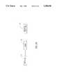
- FIGS. 2a and 2bshow pictorially the instrument 11 positioned within a vehicle 25 proximate a windshield 26 thereof and preferably glued thereto.
- the laser diode 21(FIG. 1) emits a beam of laser light having a first component 27 which is reflected by the windshield 26 and a second component 28 which passes through the windshield 26 so as to be reflected by a leading vehicle 29 in front of the vehicle 25.
- first and second components 27 and 28 of the laser beamstrike the optical detector 22, corresponding first and second detector signals are generated thereby and fed to a timer 30 which measures an elapsed time ⁇ t between receipt of the first and second components 27 and 28 of the laser beam.
- a distance computer 31 coupled to the timer 30is responsive to the elapsed time ⁇ t for determining the distance between the two vehicles.
- Such an arrangementobviates the need for synchronization between the transmission of a laser pulse and subsequent receipt thereof, since both the first and second components 27 and 28 of the laser beam are derived from the same beam and any flight time delay between the actual emission of the laser beam and receipt of the first component 27 thereof by the detector 22 is exactly compensated for by the transit time for the second component 28 of the laser beam to reach the windshield 26 from the detector 22 during its outgoing trajectory and to reach the detector 22 from the windshield 26 on its return trajectory.
- timer 30 and the distance computer 31are not provided by separate hardware circuits but, rather, are provided within the micro-controller 13.
- a safety time threshold adjustment 33is coupled to the distance computer 31 for adjusting the safety time threshold at which an alarm is given, in order to allow for different ambient conditions or wakefulness of the driver.
- a frequency of the laser diodeis randomly selected between predetermined lower and upper thresholds in respect of a specific instrument, the optical detector 22 being connected to a filter 32 for filtering out a received signal whose frequency differs from the selected frequency.
- FIG. 3shows schematically the speed transducer 15 which comprises at least one light-reflecting strip 35 adhered to an appropriate drive shaft 36 of the vehicle.
- the drive shaft 36may be one of the two drive shafts on which the front wheels 37 and 38 are mounted.
- the drive shaft 36is constituted by the common drive shaft between the gear box and the back axle (not shown).
- a light source 40emits a continuous beam of light 41 towards the axle 36 in the region of the light-reflecting strip 35 so as to be reflected thereby as a reflected beam 42 which is intercepted by a detector/counter 43 which may be optically coupled to the light-reflecting strip via an optical fiber (not shown).
- a reflected beam 42is emitted towards the detector/counter 43 each time the light-reflecting strip 35 intercepts the beam 41.
- the detector/counter 43produces a pulse each time a reflected beam 42 is detected, each of the received pulses being counted.
- the number of pulses counted in a given timein conjunction with the number of light-reflecting strips 35 provided on the axle 36, permits the number of revolutions per unit time of the axle 36 to be computed. This having been done, it is a simple matter to calculate the self-speed of the vehicle by multiplying the angular speed of the axle 36 by the radius of the wheels 37 and 38 mounted thereon.
- the digital output thereofmay be fed directly to the micro-controller 13 without the need for the components shown in FIG. 3 to be provided as separate elements.
- the arrangement shown in FIG. 3is capable of universal application and does not require special customization for different vehicles, apart from specifying the wheel radius which is the only variable in such a system.
- FIG. 4is a flow diagram showing the principal steps associated with the calculation of self-speed using the arrangement described above with reference to FIG. 3 of the drawings.
- the systemis dormant until a first pulse is received, whereupon a clock is activated, such that on receipt of subsequent pulses, the elapsed time ⁇ t between successive pulses is measured.
- a correction factoris applied, as required, whereupon the self-speed of the vehicle is calculated in accordance with the equation: ##EQU1## where: k is a constant which takes into account the number of light-reflecting strips 35 and the wheel radius, and
- ⁇ t'is the corrected elapsed time between pulses.
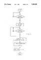
- FIGS. 5a and 5bshow the principal steps associated with the calculation of the speed V 1 of the leading vehicle and the collision time t col between the two vehicles.
- a pulseis produced which activates a clock associated with the micro-controller 13.
- a second pulseis produced when the second component of the laser beam strikes the detector 22, thereby enabling the clock to measure the elapsed time ⁇ t between the two successive pulses. Since the speed c of the laser beam is known, the distance travelled thereby during an elapsed time ⁇ t may easily be calculated. In practice, this procedure is repeated continually and the results during a given time are averaged in order to reduce inaccuracies.
- ⁇ V 1represents the closing velocity with which the following vehicle approaches the leading vehicle. Since the self-speed of the following vehicle is known, it is therefore a simple matter to calculate the actual road speed of the leading vehicle.
- the collision time between the two vehiclesmay also be calculated.
- the collision timeis equal to the distance divided by the closing velocity, ⁇ V 1 .
- most traffic lawsimpose a stricter criterion for the calculation of "safety time" between two vehicles, requiring that, the distance between the two vehicles be sufficient to enable the driver of the following vehicle to react properly even in the event that the leading vehicle stops instantaneously.
- the closing speedis equal to the self-speed of the following vehicle.
- the safety timehaving thus been calculated, it is displayed and also compared with a threshold, a buzzer being sounded in the event that the calculated safety time is less than the threshold.
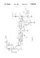
- FIG. 6shows the principal circuit components in the rangefinder 14 shown functionally in FIG. 1 of the drawings.
- a silicon PIN diode detector 45is connected to the junction 46 of a capacitor 47 connected in series with a resistor 48 and an inductance 49, a common terminal of which 50 is connected to ground GND via a capacitor 51.
- a voltage of 75 Vis fed to a free terminal of the inductance 49 via a positive supply rail 52 connected to the positive terminal of a zener diode 53 whose negative terminal is connected to GND.
- the positive supply rail 52is connected via a pull-down resistance 55 to a positive voltage supply of 200 V.
- An output 56 of the laser diode 45is connected to an input of a trans-conductance pre-amplifier shown functionally as 57, an output 58 of which is coupled via a capacitor 59 and a resistor 60 to an input 61 of a post-amplifier shown functionally as 62.
- the resistor 60is connected across the input 61 and GND.
- An output 63 of the post-amplifieris connected to a first input 64 of a fast comparator 65 a second input 66 of which is connected to a voltage reference V ref connected across a first resistor 67 in series with a capacitor 68, a low voltage terminal of which is connected to GND.
- a switch 69 in series with the capacitor 68 and the first resistor 67permits connection of a second resistor 67' to the voltage reference V ref instead of the first resistor 67.
- Coupled to an output 70 of the comparator 65is a switch shown functionally as 72 having an output thereof connected between a positive supply rail V t via a coil 75 and GND via a capacitor 76.
- An analog-to-digital (A/D) converter 78having an output 79 is connected across the capacitor 76.
- the operation of the circuitis as follows. An incoming laser pulse is detected by the PIN diode detector 45, an output of which is amplified by the trans-conductance pre-amplifier 57 in tandem with the post-amplifier 62. The output of the post-amplifier 63 is compared with V ref so that the fast comparator 65 produces an output only if the voltage appearing across its first input 64 exceeds the value of V ref .
- the capacitor 68which is fully charged sets a high threshold level for the incoming pulses, so that only very strong reflections from nearby targets are detected, thereby avoiding a major cause of false alarms.
- the capacitor 68discharges through the first resistor 67 and the threshold level V ref is lowered accordingly.
- the capacitor 70is charged through the coil 75 at a constant current.
- charging of the capacitor 76stops and a voltage measurement by the A/D converter 78 is performed.
- the voltage appearing across the output 79 of the A/D converter 78is proportional to the elapsed time ⁇ t between receipt of successive pulses by the PIN diode detector 45 and therefore to the distance between adjacent vehicles.
- the comparator 65 together with the switch 72constitute a threshold detector for adjusting the sensitivity of the rangefinder in accordance with the time constant of the capacitor 68 in series with the selected resistor 67 or 67'.
- the sensitivity of the rangefinder receivermay be increased or decreased. This is particularly useful for increasing the sensitivity of the device in adverse weather conditions, such as fog, when visibility is low so that detection of weak reflections over small distances may be effected.
- successive pulsesare, in fact, derived from first and second components of the beam being reflected by the windshield 26 of the following vehicle and by the leading vehicle, respectively.
- the elapsed timemust be measured between receipt of only that component which is reflected by the leading vehicle. This requires two threshold detectors to be employed to start charging after receiving the first component pulse reflected from the windshield of the following car, and to stop charging upon receipt of the second component pulse reflected by the leading vehicle, respectively.
- False alarmsare typically caused by the rangefinder emitting a beam which is reflected not by an adjacent vehicle but, instead, by some extraneous object such as, for example, a lamp post, a tree or even another vehicle which does not represent a danger to the following vehicle.
- Use of a laser rangefindergoes a long way to eliminating extraneous reflections by false objects since the dispersion angle of the laser beam is very small.
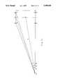
- FIG. 7ashows geometrically a vehicle 80 travelling along an inner lane 81 of a two lane highway depicted generally as 82 and having an outside lane 83, the outer wheels of the vehicle 80 lying on an inside edge 84 of the inner lane 81.
- the inner and outer lanes 81 and 83meet at a common boundary 85 and have identical widths W.
- ⁇is the dispersion angle of the laser beam
- Bis the point of intersection by a central portion of the laser beam with the adjacent lane 83
- Ais the point of intersection by the nearest part of the laser beam with adjacent lane 83
- Cis the point of intersection of the far portion of the laser beam with the adjacent lane 83
- Wis the width of each lane
- mis the width of the vehicle 80
- Ris the turning radius
- DCis the maximum distance travelled by the laser beam when reflected by a vehicle in the same lane 81 as the vehicle 80, then, considering ⁇ DBO it can be shown that: ##EQU2##
- side DCmay be calculated using the cosine rule. as follows: ##EQU3## giving a quadratic equation which can be solved for CD.
- the dispersion angle ⁇ of the laser beam, the width W of the lane and the width m of the vehicleare all constant for a particular device since road lanes are generally of constant, known width.
- the values of ⁇may easily be measured and stored within a memory (not shown) associated with the micro-controller 13 (FIG. 1), during manufacture of the device, whilst the values of W and m may likewise be stored upon installing the device in a vehicle for the first time.
- the maximum distance DCis thus a function of several stored parameters and the turning radius R and constitutes a threshold, which if exceeded by a measured propagation distance, must be rejected.
- FIG. 7cshows that the turning radius R is itself a function of the wheel base between the front and rear axles of the vehicle and the average turning angle of the front wheels which may be determined by measuring an offset angle of the steering mechanism relative to a base value when the vehicle is moving straight.
- His the wheel base of the vehicle
- ⁇is the average turning angle of the front wheels, then it may be shown that: ##EQU4##
- FIG. 8shows pictorially a vehicle 90 having a front fender 91 and a rear fender 92. Positioned on the front and rear fenders 91 and 92 are respective transducers 93 and 94 which are at heights h 1 and h 2 , respectively, above a road surface 95.
- FIG. 9relates to the situation shown in FIG. 8, and represents geometrically the effect of varying a load distribution within the vehicle 90 such that the heights h 1 and h 2 vary accordingly.
- the value of h 2decreases giving rise to a new value ⁇ ' between the road surface 95 and the imaginary line joining the two transducers 93 and 94.
- the variation in the angle ais computed in response to the height measurements provided by the transducers 93 and 94 and is fed to a servo system (not shown) connected to the rangefinder 14, so that the angle of the laser beam emitted by the rangefinder 14 may be varied in order to compensate for variations in the angle ⁇ .
Landscapes
- Physics & Mathematics (AREA)
- Engineering & Computer Science (AREA)
- Computer Networks & Wireless Communication (AREA)
- Electromagnetism (AREA)
- General Physics & Mathematics (AREA)
- Radar, Positioning & Navigation (AREA)
- Remote Sensing (AREA)
- Optical Radar Systems And Details Thereof (AREA)
Abstract
Description
ΔV.sub.1 =(S.sub.n -S.sub.n-1)×f
Claims (13)
Priority Applications (6)
| Application Number | Priority Date | Filing Date | Title |
|---|---|---|---|
| US08/017,742US5388048A (en) | 1993-02-16 | 1993-02-16 | Vehicle anti-collison device |
| EP94906333AEP0685077A1 (en) | 1993-02-16 | 1994-02-16 | A vehicle anti-collision device |
| JP6518738AJPH08507371A (en) | 1993-02-16 | 1994-02-16 | Vehicle collision prevention device |
| AU60085/94AAU6008594A (en) | 1993-02-16 | 1994-02-16 | A vehicle anti-collision device |
| IL10867094AIL108670A0 (en) | 1993-02-16 | 1994-02-16 | Vehicle anti-collision device |
| PCT/GB1994/000309WO1994019705A1 (en) | 1993-02-16 | 1994-02-16 | A vehicle anti-collision device |
Applications Claiming Priority (1)
| Application Number | Priority Date | Filing Date | Title |
|---|---|---|---|
| US08/017,742US5388048A (en) | 1993-02-16 | 1993-02-16 | Vehicle anti-collison device |
Publications (1)
| Publication Number | Publication Date |
|---|---|
| US5388048Atrue US5388048A (en) | 1995-02-07 |
Family
ID=21784284
Family Applications (1)
| Application Number | Title | Priority Date | Filing Date |
|---|---|---|---|
| US08/017,742Expired - Fee RelatedUS5388048A (en) | 1993-02-16 | 1993-02-16 | Vehicle anti-collison device |
Country Status (2)
| Country | Link |
|---|---|
| US (1) | US5388048A (en) |
| IL (1) | IL108670A0 (en) |
Cited By (48)
| Publication number | Priority date | Publication date | Assignee | Title |
|---|---|---|---|---|
| US5572428A (en)* | 1993-09-30 | 1996-11-05 | Honda Giken Kogyo Kabushiki Kaisha | Anti-collision system for vehicles |
| US5627510A (en)* | 1994-09-12 | 1997-05-06 | Yuan; Zhiping | Vehicular safety distance alarm system |
| US5638163A (en)* | 1995-06-07 | 1997-06-10 | Hughes Electronics | Low cost laser range finder system architecture |
| US5648905A (en)* | 1993-12-07 | 1997-07-15 | Mazda Motor Corporation | Traveling control system for motor vehicle |
| US5656992A (en)* | 1996-03-25 | 1997-08-12 | Mcneill; Sheila Ann | Externally mounted vehicle speedometer display |
| US5659304A (en)* | 1995-03-01 | 1997-08-19 | Eaton Corporation | System and method for collision warning based on dynamic deceleration capability using predicted road load |
| WO1997016059A3 (en)* | 1995-10-16 | 1997-08-21 | Donald Wayne Smith | The vehicle awareness alerter it is a full communication computer system for vehicles |
| US5675518A (en)* | 1995-05-11 | 1997-10-07 | Hitachi, Ltd. | Inter-vehicle distance measuring apparatus and method for automotive |
| US5761629A (en)* | 1994-12-13 | 1998-06-02 | Lucas Industries Public Limited Company | Method and apparatus for cruise control |
| US5839534A (en)* | 1995-03-01 | 1998-11-24 | Eaton Vorad Technologies, Llc | System and method for intelligent cruise control using standard engine control modes |
| US5931547A (en)* | 1997-03-05 | 1999-08-03 | Lerner; Meir Yisochor | Anti-collision system |
| US5978736A (en)* | 1992-11-20 | 1999-11-02 | Gec-Marconi Avionics (Holdings) Ltd. | Vehicle obstruction detection system |
| US6014601A (en)* | 1997-01-07 | 2000-01-11 | J. Martin Gustafson | Driver alert system |
| US6034764A (en)* | 1996-03-20 | 2000-03-07 | Carter; Robert J. | Portable electronic distance and vertical angle instrument |
| US6157892A (en)* | 1998-06-11 | 2000-12-05 | Honda Giken Kogyo Kabushiki Kaisha | Obstacle avoidance control system for vehicle |
| US6198386B1 (en) | 1998-10-02 | 2001-03-06 | White, Ii Locke | Vehicle guidance assembly and method |
| US6223117B1 (en)* | 1997-05-27 | 2001-04-24 | General Motors Corporation | Cut-in management for an adaptive cruise control system |
| US6225918B1 (en) | 1999-02-19 | 2001-05-01 | Bing Kam | Automatic warning signal system for vehicles |
| US6408247B1 (en)* | 1999-04-28 | 2002-06-18 | Honda Giken Kogyo Kabushiki Kaisha | Obstacle detecting system |
| US20030036881A1 (en)* | 2000-06-22 | 2003-02-20 | Ford Global Technologies, Inc. | System and method for detecting an object using pulsed light |
| US6590495B1 (en)* | 2001-12-11 | 2003-07-08 | Iraj Behbehani | Automobile distance warning and alarm system |
| US6679702B1 (en) | 2001-12-18 | 2004-01-20 | Paul S. Rau | Vehicle-based headway distance training system |
| WO2004045894A1 (en)* | 2002-11-21 | 2004-06-03 | Lucas Automotive Gmbh | System for influencing the speed of a motor vehicle |
| US6795765B2 (en) | 2001-03-22 | 2004-09-21 | Visteon Global Technologies, Inc. | Tracking of a target vehicle using adaptive cruise control |
| US20050156102A1 (en)* | 2001-07-20 | 2005-07-21 | Walter Hagleitner | Optical sensor arrangement |
| US20050190047A1 (en)* | 2004-02-26 | 2005-09-01 | Lemke Richard G. | Collision avoidance system for snowmobiles |
| US20050209764A1 (en)* | 2002-11-21 | 2005-09-22 | Marko Schroder | System for recognizing left-hand or right-hand driving conditions |
| US20050216170A1 (en)* | 2002-11-21 | 2005-09-29 | Lucas Automotive Gmbh | System for influencing the spread of a motor vehicle |
| US20050216137A1 (en)* | 2002-11-21 | 2005-09-29 | Marko Schroder | System for influencing the speed of a motor vehicle |
| US20050216171A1 (en)* | 2002-11-21 | 2005-09-29 | Lucas Automotive Gmbh | System for recognising the lane-change manoeuver of a motor vehicle |
| US20050216172A1 (en)* | 2002-11-21 | 2005-09-29 | Marko Schroder | System for influencing the speed of a motor vehicle |
| US20050240335A1 (en)* | 2002-11-21 | 2005-10-27 | Lucas Automotive Gmbh | System for influencing the speed of a motor vehicle |
| US20050240330A1 (en)* | 2002-11-21 | 2005-10-27 | Lucas Automotive Gmbh | System for influencing the speed of a motor vehicle |
| US20050251323A1 (en)* | 2002-11-21 | 2005-11-10 | Lucas Automotive Gmbh | System for influencing the speed of a motor vehicle |
| US20050251313A1 (en)* | 2002-11-21 | 2005-11-10 | Lucas Automotive Gmbh | System for influencing the speed of a motor vehicle |
| US20110181457A1 (en)* | 2008-08-22 | 2011-07-28 | Mark Basten | Vehicle Length Sensors |
| US20110246071A1 (en)* | 2008-12-24 | 2011-10-06 | Toyota Jidosha Kabushiki Kaisha | Collision determination device |
| US8775015B2 (en)* | 2012-07-20 | 2014-07-08 | Wistron Corp. | Vehicle collision event announcing system and method |
| US8818042B2 (en) | 2004-04-15 | 2014-08-26 | Magna Electronics Inc. | Driver assistance system for vehicle |
| US8842176B2 (en) | 1996-05-22 | 2014-09-23 | Donnelly Corporation | Automatic vehicle exterior light control |
| US8917169B2 (en) | 1993-02-26 | 2014-12-23 | Magna Electronics Inc. | Vehicular vision system |
| US8977008B2 (en) | 2004-09-30 | 2015-03-10 | Donnelly Corporation | Driver assistance system for vehicle |
| US8993951B2 (en) | 1996-03-25 | 2015-03-31 | Magna Electronics Inc. | Driver assistance system for a vehicle |
| CN104960467A (en)* | 2015-05-27 | 2015-10-07 | 苏州合欣美电子科技有限公司 | Anti-collision device based on laser technology |
| US9171217B2 (en) | 2002-05-03 | 2015-10-27 | Magna Electronics Inc. | Vision system for vehicle |
| US9436880B2 (en) | 1999-08-12 | 2016-09-06 | Magna Electronics Inc. | Vehicle vision system |
| US9440535B2 (en) | 2006-08-11 | 2016-09-13 | Magna Electronics Inc. | Vision system for vehicle |
| US10429506B2 (en)* | 2014-10-22 | 2019-10-01 | Denso Corporation | Lateral distance sensor diagnosis apparatus |
Citations (34)
| Publication number | Priority date | Publication date | Assignee | Title |
|---|---|---|---|---|
| US2142378A (en)* | 1936-12-23 | 1939-01-03 | Rca Corp | Photoelectric velocity detector |
| US3313945A (en)* | 1963-08-27 | 1967-04-11 | James R Clinton | Apparatus for sensing variations in light reflectivity of a moving surface |
| US3446979A (en)* | 1965-07-20 | 1969-05-27 | Ronald J Ricciardi | Flow indicator for divided solid material provided with indicia responsive photoelectric means |
| US3486032A (en)* | 1966-07-19 | 1969-12-23 | Marconi Co Ltd | Apparatus for measuring speed comprising a light-electric translating device |
| US3519351A (en)* | 1967-10-27 | 1970-07-07 | Seismograph Service Corp | Non-contact speed measurement |
| US3704445A (en)* | 1971-07-20 | 1972-11-28 | Richard R Lanham | Digital read out indicator for vehicles |
| US3731301A (en)* | 1971-07-06 | 1973-05-01 | Plessey Handel Investment Ag | Methods of detecting rotation speed |
| US3749197A (en)* | 1971-05-12 | 1973-07-31 | B Deutsch | Obstacle detection system |
| US3856403A (en)* | 1971-02-19 | 1974-12-24 | Litton Systems Inc | Velocity biased laser velocimeter |
| US3949359A (en)* | 1970-04-30 | 1976-04-06 | Trw Inc. | Digital speed control |
| US4387785A (en)* | 1979-09-12 | 1983-06-14 | Siemens Aktiengesellschaft | Optical device for monitoring critical speeds of a rotating member |
| US4418288A (en)* | 1981-01-29 | 1983-11-29 | Toyota Jidosha Kogyo Kabushiki Kaisha | Rotation detector |
| JPS5924278A (en)* | 1982-07-31 | 1984-02-07 | Nippon Soken Inc | Obstackle detecting apparatus for vehicle |
| GB2139445A (en)* | 1983-05-06 | 1984-11-07 | Nissan Motor | Vehicle lidar |
| US4502045A (en)* | 1979-09-12 | 1985-02-26 | Siemens Aktiengesellschaft | Optical device for monitoring critical speeds of a rotating member |
| US4580130A (en)* | 1983-04-13 | 1986-04-01 | Alps Electric Co., Ltd. | Rotary encoder |
| US4673809A (en)* | 1983-03-22 | 1987-06-16 | Siemens Aktiengesellschaft | Optoelectronic scanning arrangement wherein optical reflective markings form curvilinear arcs |
| US4706195A (en)* | 1984-06-15 | 1987-11-10 | Nippon Soken, Inc. | Speed control system for a motor vehicle |
| US4757450A (en)* | 1985-06-03 | 1988-07-12 | Nissan Motor Company, Limited | Method and system for automatically detecting a preceding vehicle |
| US4766421A (en)* | 1986-02-19 | 1988-08-23 | Auto-Sense, Ltd. | Object detection apparatus employing electro-optics |
| US4767164A (en)* | 1985-10-09 | 1988-08-30 | Crane Co. | Fiber optic rotation rate encoder |
| US4866987A (en)* | 1987-07-10 | 1989-09-19 | Schlumberger Industries Limited | Optical transducer systems |
| US4872051A (en)* | 1987-10-01 | 1989-10-03 | Environmental Research Institute Of Michigan | Collision avoidance alarm system |
| US4948246A (en)* | 1988-02-22 | 1990-08-14 | Toyota Jidosha Kabushiki Kaisha | Leading-vehicle detection apparatus |
| US4987299A (en)* | 1988-08-24 | 1991-01-22 | Ricoh Company, Ltd. | Rotation quantity measuring method and system |
| US5014200A (en)* | 1990-02-20 | 1991-05-07 | General Motors Corporation | Adaptive cruise system |
| US5059901A (en)* | 1990-05-04 | 1991-10-22 | Technology For Energy Corporation | Visible light laser tachometer for sensing rotational speed of an object |
| EP0473866A2 (en)* | 1990-08-22 | 1992-03-11 | Kollmorgen Corporation | Collision avoidance system |
| US5103213A (en)* | 1990-06-25 | 1992-04-07 | Bindicator Company | Shaft rotation monitoring apparatus |
| US5153559A (en)* | 1990-06-27 | 1992-10-06 | A.C.E. Corporation | Equipment for detecting the movement of a preceding vehicle and giving warning |
| US5166881A (en)* | 1990-01-17 | 1992-11-24 | Mitsubishi Denki K.K. | Following control apparatus for an automotive vehicle |
| US5230400A (en)* | 1990-11-30 | 1993-07-27 | Aisin Seiki Kabushiki Kaisha | Vehicle cruise control system |
| US5234071A (en)* | 1991-02-26 | 1993-08-10 | Mitsubishi Denki Kabushiki Kaisha | Travel control apparatus for motor a vehicle |
| US5278764A (en)* | 1990-01-29 | 1994-01-11 | Nissan Motor Company, Limited | Automatic braking system with proximity detection to a preceding vehicle |
- 1993
- 1993-02-16USUS08/017,742patent/US5388048A/ennot_activeExpired - Fee Related
- 1994
- 1994-02-16ILIL10867094Apatent/IL108670A0/enunknown
Patent Citations (34)
| Publication number | Priority date | Publication date | Assignee | Title |
|---|---|---|---|---|
| US2142378A (en)* | 1936-12-23 | 1939-01-03 | Rca Corp | Photoelectric velocity detector |
| US3313945A (en)* | 1963-08-27 | 1967-04-11 | James R Clinton | Apparatus for sensing variations in light reflectivity of a moving surface |
| US3446979A (en)* | 1965-07-20 | 1969-05-27 | Ronald J Ricciardi | Flow indicator for divided solid material provided with indicia responsive photoelectric means |
| US3486032A (en)* | 1966-07-19 | 1969-12-23 | Marconi Co Ltd | Apparatus for measuring speed comprising a light-electric translating device |
| US3519351A (en)* | 1967-10-27 | 1970-07-07 | Seismograph Service Corp | Non-contact speed measurement |
| US3949359A (en)* | 1970-04-30 | 1976-04-06 | Trw Inc. | Digital speed control |
| US3856403A (en)* | 1971-02-19 | 1974-12-24 | Litton Systems Inc | Velocity biased laser velocimeter |
| US3749197A (en)* | 1971-05-12 | 1973-07-31 | B Deutsch | Obstacle detection system |
| US3731301A (en)* | 1971-07-06 | 1973-05-01 | Plessey Handel Investment Ag | Methods of detecting rotation speed |
| US3704445A (en)* | 1971-07-20 | 1972-11-28 | Richard R Lanham | Digital read out indicator for vehicles |
| US4502045A (en)* | 1979-09-12 | 1985-02-26 | Siemens Aktiengesellschaft | Optical device for monitoring critical speeds of a rotating member |
| US4387785A (en)* | 1979-09-12 | 1983-06-14 | Siemens Aktiengesellschaft | Optical device for monitoring critical speeds of a rotating member |
| US4418288A (en)* | 1981-01-29 | 1983-11-29 | Toyota Jidosha Kogyo Kabushiki Kaisha | Rotation detector |
| JPS5924278A (en)* | 1982-07-31 | 1984-02-07 | Nippon Soken Inc | Obstackle detecting apparatus for vehicle |
| US4673809A (en)* | 1983-03-22 | 1987-06-16 | Siemens Aktiengesellschaft | Optoelectronic scanning arrangement wherein optical reflective markings form curvilinear arcs |
| US4580130A (en)* | 1983-04-13 | 1986-04-01 | Alps Electric Co., Ltd. | Rotary encoder |
| GB2139445A (en)* | 1983-05-06 | 1984-11-07 | Nissan Motor | Vehicle lidar |
| US4706195A (en)* | 1984-06-15 | 1987-11-10 | Nippon Soken, Inc. | Speed control system for a motor vehicle |
| US4757450A (en)* | 1985-06-03 | 1988-07-12 | Nissan Motor Company, Limited | Method and system for automatically detecting a preceding vehicle |
| US4767164A (en)* | 1985-10-09 | 1988-08-30 | Crane Co. | Fiber optic rotation rate encoder |
| US4766421A (en)* | 1986-02-19 | 1988-08-23 | Auto-Sense, Ltd. | Object detection apparatus employing electro-optics |
| US4866987A (en)* | 1987-07-10 | 1989-09-19 | Schlumberger Industries Limited | Optical transducer systems |
| US4872051A (en)* | 1987-10-01 | 1989-10-03 | Environmental Research Institute Of Michigan | Collision avoidance alarm system |
| US4948246A (en)* | 1988-02-22 | 1990-08-14 | Toyota Jidosha Kabushiki Kaisha | Leading-vehicle detection apparatus |
| US4987299A (en)* | 1988-08-24 | 1991-01-22 | Ricoh Company, Ltd. | Rotation quantity measuring method and system |
| US5166881A (en)* | 1990-01-17 | 1992-11-24 | Mitsubishi Denki K.K. | Following control apparatus for an automotive vehicle |
| US5278764A (en)* | 1990-01-29 | 1994-01-11 | Nissan Motor Company, Limited | Automatic braking system with proximity detection to a preceding vehicle |
| US5014200A (en)* | 1990-02-20 | 1991-05-07 | General Motors Corporation | Adaptive cruise system |
| US5059901A (en)* | 1990-05-04 | 1991-10-22 | Technology For Energy Corporation | Visible light laser tachometer for sensing rotational speed of an object |
| US5103213A (en)* | 1990-06-25 | 1992-04-07 | Bindicator Company | Shaft rotation monitoring apparatus |
| US5153559A (en)* | 1990-06-27 | 1992-10-06 | A.C.E. Corporation | Equipment for detecting the movement of a preceding vehicle and giving warning |
| EP0473866A2 (en)* | 1990-08-22 | 1992-03-11 | Kollmorgen Corporation | Collision avoidance system |
| US5230400A (en)* | 1990-11-30 | 1993-07-27 | Aisin Seiki Kabushiki Kaisha | Vehicle cruise control system |
| US5234071A (en)* | 1991-02-26 | 1993-08-10 | Mitsubishi Denki Kabushiki Kaisha | Travel control apparatus for motor a vehicle |
Cited By (90)
| Publication number | Priority date | Publication date | Assignee | Title |
|---|---|---|---|---|
| US5978736A (en)* | 1992-11-20 | 1999-11-02 | Gec-Marconi Avionics (Holdings) Ltd. | Vehicle obstruction detection system |
| US8917169B2 (en) | 1993-02-26 | 2014-12-23 | Magna Electronics Inc. | Vehicular vision system |
| US5572428A (en)* | 1993-09-30 | 1996-11-05 | Honda Giken Kogyo Kabushiki Kaisha | Anti-collision system for vehicles |
| US5648905A (en)* | 1993-12-07 | 1997-07-15 | Mazda Motor Corporation | Traveling control system for motor vehicle |
| US5627510A (en)* | 1994-09-12 | 1997-05-06 | Yuan; Zhiping | Vehicular safety distance alarm system |
| US5761629A (en)* | 1994-12-13 | 1998-06-02 | Lucas Industries Public Limited Company | Method and apparatus for cruise control |
| US5839534A (en)* | 1995-03-01 | 1998-11-24 | Eaton Vorad Technologies, Llc | System and method for intelligent cruise control using standard engine control modes |
| US5659304A (en)* | 1995-03-01 | 1997-08-19 | Eaton Corporation | System and method for collision warning based on dynamic deceleration capability using predicted road load |
| US6076622A (en)* | 1995-03-01 | 2000-06-20 | Eaton Vorad Technologies, Llc | System and method for intelligent cruise control using standard engine control modes |
| US5675518A (en)* | 1995-05-11 | 1997-10-07 | Hitachi, Ltd. | Inter-vehicle distance measuring apparatus and method for automotive |
| US5638163A (en)* | 1995-06-07 | 1997-06-10 | Hughes Electronics | Low cost laser range finder system architecture |
| WO1997016059A3 (en)* | 1995-10-16 | 1997-08-21 | Donald Wayne Smith | The vehicle awareness alerter it is a full communication computer system for vehicles |
| US6034764A (en)* | 1996-03-20 | 2000-03-07 | Carter; Robert J. | Portable electronic distance and vertical angle instrument |
| US5656992A (en)* | 1996-03-25 | 1997-08-12 | Mcneill; Sheila Ann | Externally mounted vehicle speedometer display |
| US8993951B2 (en) | 1996-03-25 | 2015-03-31 | Magna Electronics Inc. | Driver assistance system for a vehicle |
| US8842176B2 (en) | 1996-05-22 | 2014-09-23 | Donnelly Corporation | Automatic vehicle exterior light control |
| US6014601A (en)* | 1997-01-07 | 2000-01-11 | J. Martin Gustafson | Driver alert system |
| US5931547A (en)* | 1997-03-05 | 1999-08-03 | Lerner; Meir Yisochor | Anti-collision system |
| US6223117B1 (en)* | 1997-05-27 | 2001-04-24 | General Motors Corporation | Cut-in management for an adaptive cruise control system |
| US6157892A (en)* | 1998-06-11 | 2000-12-05 | Honda Giken Kogyo Kabushiki Kaisha | Obstacle avoidance control system for vehicle |
| US6198386B1 (en) | 1998-10-02 | 2001-03-06 | White, Ii Locke | Vehicle guidance assembly and method |
| US6225918B1 (en) | 1999-02-19 | 2001-05-01 | Bing Kam | Automatic warning signal system for vehicles |
| US6408247B1 (en)* | 1999-04-28 | 2002-06-18 | Honda Giken Kogyo Kabushiki Kaisha | Obstacle detecting system |
| US9436880B2 (en) | 1999-08-12 | 2016-09-06 | Magna Electronics Inc. | Vehicle vision system |
| US7079974B2 (en)* | 2000-06-22 | 2006-07-18 | Ford Global Technologies, Llc | System and method for detecting an object using pulsed light |
| US20030036881A1 (en)* | 2000-06-22 | 2003-02-20 | Ford Global Technologies, Inc. | System and method for detecting an object using pulsed light |
| US6795765B2 (en) | 2001-03-22 | 2004-09-21 | Visteon Global Technologies, Inc. | Tracking of a target vehicle using adaptive cruise control |
| US7236234B2 (en)* | 2001-07-20 | 2007-06-26 | Automotive Distance Control Systems Gmbh | Optical sensor arrangement |
| US20050156102A1 (en)* | 2001-07-20 | 2005-07-21 | Walter Hagleitner | Optical sensor arrangement |
| US6590495B1 (en)* | 2001-12-11 | 2003-07-08 | Iraj Behbehani | Automobile distance warning and alarm system |
| US6679702B1 (en) | 2001-12-18 | 2004-01-20 | Paul S. Rau | Vehicle-based headway distance training system |
| US10683008B2 (en) | 2002-05-03 | 2020-06-16 | Magna Electronics Inc. | Vehicular driving assist system using forward-viewing camera |
| US9555803B2 (en) | 2002-05-03 | 2017-01-31 | Magna Electronics Inc. | Driver assistance system for vehicle |
| US9171217B2 (en) | 2002-05-03 | 2015-10-27 | Magna Electronics Inc. | Vision system for vehicle |
| US9643605B2 (en) | 2002-05-03 | 2017-05-09 | Magna Electronics Inc. | Vision system for vehicle |
| US9834216B2 (en) | 2002-05-03 | 2017-12-05 | Magna Electronics Inc. | Vehicular control system using cameras and radar sensor |
| US10118618B2 (en) | 2002-05-03 | 2018-11-06 | Magna Electronics Inc. | Vehicular control system using cameras and radar sensor |
| US10351135B2 (en) | 2002-05-03 | 2019-07-16 | Magna Electronics Inc. | Vehicular control system using cameras and radar sensor |
| US11203340B2 (en) | 2002-05-03 | 2021-12-21 | Magna Electronics Inc. | Vehicular vision system using side-viewing camera |
| US7831368B2 (en) | 2002-11-21 | 2010-11-09 | Lucas Automotive Gmbh | System for influencing the speed of a motor vehicle |
| US20050216171A1 (en)* | 2002-11-21 | 2005-09-29 | Lucas Automotive Gmbh | System for recognising the lane-change manoeuver of a motor vehicle |
| US7248962B2 (en) | 2002-11-21 | 2007-07-24 | Lucas Automotive Gmbh | System for influencing the speed of a motor vehicle |
| US7386385B2 (en) | 2002-11-21 | 2008-06-10 | Lucas Automotive Gmbh | System for recognising the lane-change manoeuver of a motor vehicle |
| US7774123B2 (en) | 2002-11-21 | 2010-08-10 | Lucas Automotive Gmbh | System for influencing the speed of a motor vehicle |
| US7177750B2 (en) | 2002-11-21 | 2007-02-13 | Lucas Automotive Gmbh | System for influencing the speed of a motor vehicle |
| US7831367B2 (en) | 2002-11-21 | 2010-11-09 | Lucas Automotive Gmbh | System for influencing the speed of a motor vehicle |
| US7840330B2 (en) | 2002-11-21 | 2010-11-23 | Lucas Automotive Gmbh | System for influencing the speed of a motor vehicle |
| WO2004045894A1 (en)* | 2002-11-21 | 2004-06-03 | Lucas Automotive Gmbh | System for influencing the speed of a motor vehicle |
| US20050240335A1 (en)* | 2002-11-21 | 2005-10-27 | Lucas Automotive Gmbh | System for influencing the speed of a motor vehicle |
| US20050209764A1 (en)* | 2002-11-21 | 2005-09-22 | Marko Schroder | System for recognizing left-hand or right-hand driving conditions |
| US20050216170A1 (en)* | 2002-11-21 | 2005-09-29 | Lucas Automotive Gmbh | System for influencing the spread of a motor vehicle |
| US20050216137A1 (en)* | 2002-11-21 | 2005-09-29 | Marko Schroder | System for influencing the speed of a motor vehicle |
| US20050240330A1 (en)* | 2002-11-21 | 2005-10-27 | Lucas Automotive Gmbh | System for influencing the speed of a motor vehicle |
| US20050216172A1 (en)* | 2002-11-21 | 2005-09-29 | Marko Schroder | System for influencing the speed of a motor vehicle |
| US20050251313A1 (en)* | 2002-11-21 | 2005-11-10 | Lucas Automotive Gmbh | System for influencing the speed of a motor vehicle |
| US7212907B2 (en) | 2002-11-21 | 2007-05-01 | Lucas Automotive Gmbh | System for influencing the speed of a motor vehicle |
| US20050251323A1 (en)* | 2002-11-21 | 2005-11-10 | Lucas Automotive Gmbh | System for influencing the speed of a motor vehicle |
| US7095315B2 (en) | 2004-02-26 | 2006-08-22 | Lemke Richard G | Collision avoidance system for snowmobiles |
| US20050190047A1 (en)* | 2004-02-26 | 2005-09-01 | Lemke Richard G. | Collision avoidance system for snowmobiles |
| US9609289B2 (en) | 2004-04-15 | 2017-03-28 | Magna Electronics Inc. | Vision system for vehicle |
| US10187615B1 (en) | 2004-04-15 | 2019-01-22 | Magna Electronics Inc. | Vehicular control system |
| US9428192B2 (en) | 2004-04-15 | 2016-08-30 | Magna Electronics Inc. | Vision system for vehicle |
| US11847836B2 (en) | 2004-04-15 | 2023-12-19 | Magna Electronics Inc. | Vehicular control system with road curvature determination |
| US11503253B2 (en) | 2004-04-15 | 2022-11-15 | Magna Electronics Inc. | Vehicular control system with traffic lane detection |
| US9008369B2 (en) | 2004-04-15 | 2015-04-14 | Magna Electronics Inc. | Vision system for vehicle |
| US10735695B2 (en) | 2004-04-15 | 2020-08-04 | Magna Electronics Inc. | Vehicular control system with traffic lane detection |
| US8818042B2 (en) | 2004-04-15 | 2014-08-26 | Magna Electronics Inc. | Driver assistance system for vehicle |
| US9736435B2 (en) | 2004-04-15 | 2017-08-15 | Magna Electronics Inc. | Vision system for vehicle |
| US10462426B2 (en) | 2004-04-15 | 2019-10-29 | Magna Electronics Inc. | Vehicular control system |
| US9948904B2 (en) | 2004-04-15 | 2018-04-17 | Magna Electronics Inc. | Vision system for vehicle |
| US10015452B1 (en) | 2004-04-15 | 2018-07-03 | Magna Electronics Inc. | Vehicular control system |
| US10306190B1 (en) | 2004-04-15 | 2019-05-28 | Magna Electronics Inc. | Vehicular control system |
| US10110860B1 (en) | 2004-04-15 | 2018-10-23 | Magna Electronics Inc. | Vehicular control system |
| US9191634B2 (en) | 2004-04-15 | 2015-11-17 | Magna Electronics Inc. | Vision system for vehicle |
| US10623704B2 (en) | 2004-09-30 | 2020-04-14 | Donnelly Corporation | Driver assistance system for vehicle |
| US8977008B2 (en) | 2004-09-30 | 2015-03-10 | Donnelly Corporation | Driver assistance system for vehicle |
| US9440535B2 (en) | 2006-08-11 | 2016-09-13 | Magna Electronics Inc. | Vision system for vehicle |
| US11148583B2 (en) | 2006-08-11 | 2021-10-19 | Magna Electronics Inc. | Vehicular forward viewing image capture system |
| US11951900B2 (en) | 2006-08-11 | 2024-04-09 | Magna Electronics Inc. | Vehicular forward viewing image capture system |
| US11623559B2 (en) | 2006-08-11 | 2023-04-11 | Magna Electronics Inc. | Vehicular forward viewing image capture system |
| US11396257B2 (en) | 2006-08-11 | 2022-07-26 | Magna Electronics Inc. | Vehicular forward viewing image capture system |
| US10071676B2 (en) | 2006-08-11 | 2018-09-11 | Magna Electronics Inc. | Vision system for vehicle |
| US10787116B2 (en) | 2006-08-11 | 2020-09-29 | Magna Electronics Inc. | Adaptive forward lighting system for vehicle comprising a control that adjusts the headlamp beam in response to processing of image data captured by a camera |
| US8576115B2 (en)* | 2008-08-22 | 2013-11-05 | Trw Automotive Us Llc | Vehicle length sensors |
| US20110181457A1 (en)* | 2008-08-22 | 2011-07-28 | Mark Basten | Vehicle Length Sensors |
| US20110246071A1 (en)* | 2008-12-24 | 2011-10-06 | Toyota Jidosha Kabushiki Kaisha | Collision determination device |
| US8483944B2 (en)* | 2008-12-24 | 2013-07-09 | Toyota Jidosha Kabushiki Kaisha | Collision determination device |
| US8775015B2 (en)* | 2012-07-20 | 2014-07-08 | Wistron Corp. | Vehicle collision event announcing system and method |
| US10429506B2 (en)* | 2014-10-22 | 2019-10-01 | Denso Corporation | Lateral distance sensor diagnosis apparatus |
| CN104960467A (en)* | 2015-05-27 | 2015-10-07 | 苏州合欣美电子科技有限公司 | Anti-collision device based on laser technology |
Also Published As
| Publication number | Publication date |
|---|---|
| IL108670A0 (en) | 1994-05-30 |
Similar Documents
| Publication | Publication Date | Title |
|---|---|---|
| US5388048A (en) | Vehicle anti-collison device | |
| EP0685077A1 (en) | A vehicle anti-collision device | |
| US6363326B1 (en) | Method and apparatus for detecting an object on a side of or backwards of a vehicle | |
| US5701122A (en) | Electronic curb feeler | |
| US5314037A (en) | Automobile collision avoidance system | |
| US5446291A (en) | Method for classifying vehicles passing a predetermined waypoint | |
| US5574426A (en) | Obstacle detection system for vehicles moving in reverse | |
| US5321490A (en) | Active near-field object sensor and method employing object classification techniques | |
| US7271762B2 (en) | Method for detecting an obstacle around a vehicle | |
| US7218208B2 (en) | Object detecting system for vehicle | |
| US6498570B2 (en) | Optical highway line detector | |
| US5592157A (en) | Relative visibility measuring process and device | |
| US5752215A (en) | Apparatus and method for classifying vehicles using electromagnetic waves and pattern recognition | |
| JPH0830734B2 (en) | How to determine visibility | |
| US7107144B2 (en) | Non-intrusive traffic monitoring system | |
| US3786507A (en) | Vehicle anti-collision system | |
| US6097476A (en) | Distance measuring apparatus | |
| SE503046C2 (en) | Device for optical measurement of the steering angle when drawing aircraft on the ground | |
| WO2001048726A1 (en) | Following distance warning system for a vehicle | |
| GB2260209A (en) | Braking distance indicating and warning device | |
| US6072173A (en) | Animal body detecting system utilizing electromagnetic waves | |
| WO1992021116A1 (en) | Vehicle collision avoidance | |
| JPH0587565A (en) | Distance detector | |
| JPH0680436B2 (en) | Airborne particle detector | |
| JP3241906B2 (en) | In-vehicle object detection device using laser light |
Legal Events
| Date | Code | Title | Description |
|---|---|---|---|
| AS | Assignment | Owner name:SILICON HEIGHTS LTD., ISRAEL Free format text:ASSIGNMENT OF ASSIGNORS INTEREST.;ASSIGNORS:YAVNAYI, AMOTZ;GAVISH, MOSHE;SCHECHNER, PINCHAS;AND OTHERS;REEL/FRAME:006439/0791 Effective date:19930207 | |
| REMI | Maintenance fee reminder mailed | ||
| FEPP | Fee payment procedure | Free format text:PETITION RELATED TO MAINTENANCE FEES FILED (ORIGINAL EVENT CODE: PMFP); ENTITY STATUS OF PATENT OWNER: SMALL ENTITY | |
| FEPP | Fee payment procedure | Free format text:PETITION RELATED TO MAINTENANCE FEES GRANTED (ORIGINAL EVENT CODE: PMFG); ENTITY STATUS OF PATENT OWNER: SMALL ENTITY | |
| FP | Lapsed due to failure to pay maintenance fee | Effective date:19990207 | |
| FPAY | Fee payment | Year of fee payment:4 | |
| SULP | Surcharge for late payment | ||
| FEPP | Fee payment procedure | Free format text:PAYOR NUMBER ASSIGNED (ORIGINAL EVENT CODE: ASPN); ENTITY STATUS OF PATENT OWNER: SMALL ENTITY Free format text:PAYER NUMBER DE-ASSIGNED (ORIGINAL EVENT CODE: RMPN); ENTITY STATUS OF PATENT OWNER: SMALL ENTITY | |
| FPAY | Fee payment | Year of fee payment:8 | |
| REMI | Maintenance fee reminder mailed | ||
| LAPS | Lapse for failure to pay maintenance fees | ||
| STCH | Information on status: patent discontinuation | Free format text:PATENT EXPIRED DUE TO NONPAYMENT OF MAINTENANCE FEES UNDER 37 CFR 1.362 | |
| FP | Lapsed due to failure to pay maintenance fee | Effective date:20070207 |