US5387735A - Sharps disposal container and system - Google Patents
Sharps disposal container and systemDownload PDFInfo
- Publication number
- US5387735A US5387735AUS08/044,590US4459093AUS5387735AUS 5387735 AUS5387735 AUS 5387735AUS 4459093 AUS4459093 AUS 4459093AUS 5387735 AUS5387735 AUS 5387735A
- Authority
- US
- United States
- Prior art keywords
- closure
- opening
- constriction
- disposal
- container
- Prior art date
- Legal status (The legal status is an assumption and is not a legal conclusion. Google has not performed a legal analysis and makes no representation as to the accuracy of the status listed.)
- Expired - Lifetime
Links
- 230000014759maintenance of locationEffects0.000claimsabstractdescription12
- 230000004888barrier functionEffects0.000claimsabstractdescription10
- 230000004913activationEffects0.000claimsdescription3
- 230000000295complement effectEffects0.000abstract1
- 201000010099diseaseDiseases0.000description2
- 208000037265diseases, disorders, signs and symptomsDiseases0.000description2
- 239000000463materialSubstances0.000description2
- 239000012780transparent materialSubstances0.000description2
- 208000035473Communicable diseaseDiseases0.000description1
- 238000011109contaminationMethods0.000description1
- 238000004519manufacturing processMethods0.000description1
- 238000000034methodMethods0.000description1
- 239000002991molded plasticSubstances0.000description1
- 230000002093peripheral effectEffects0.000description1
- 239000004033plasticSubstances0.000description1
- 230000002265preventionEffects0.000description1
- 238000007493shaping processMethods0.000description1
- 239000002699waste materialSubstances0.000description1
Images


Classifications
- B—PERFORMING OPERATIONS; TRANSPORTING
- B65—CONVEYING; PACKING; STORING; HANDLING THIN OR FILAMENTARY MATERIAL
- B65F—GATHERING OR REMOVAL OF DOMESTIC OR LIKE REFUSE
- B65F1/00—Refuse receptacles; Accessories therefor
- B65F1/10—Refuse receptacles; Accessories therefor with refuse filling means, e.g. air-locks
- A—HUMAN NECESSITIES
- A61—MEDICAL OR VETERINARY SCIENCE; HYGIENE
- A61B—DIAGNOSIS; SURGERY; IDENTIFICATION
- A61B50/00—Containers, covers, furniture or holders specially adapted for surgical or diagnostic appliances or instruments, e.g. sterile covers
- A61B50/30—Containers specially adapted for packaging, protecting, dispensing, collecting or disposing of surgical or diagnostic appliances or instruments
- A61B50/36—Containers specially adapted for packaging, protecting, dispensing, collecting or disposing of surgical or diagnostic appliances or instruments for collecting or disposing of used articles
- A61B50/362—Containers specially adapted for packaging, protecting, dispensing, collecting or disposing of surgical or diagnostic appliances or instruments for collecting or disposing of used articles for sharps
- A—HUMAN NECESSITIES
- A61—MEDICAL OR VETERINARY SCIENCE; HYGIENE
- A61B—DIAGNOSIS; SURGERY; IDENTIFICATION
- A61B50/00—Containers, covers, furniture or holders specially adapted for surgical or diagnostic appliances or instruments, e.g. sterile covers
- A61B2050/005—Containers, covers, furniture or holders specially adapted for surgical or diagnostic appliances or instruments, e.g. sterile covers with a lid or cover
- A61B2050/0051—Containers, covers, furniture or holders specially adapted for surgical or diagnostic appliances or instruments, e.g. sterile covers with a lid or cover closable by rotation
- A61B2050/0056—Containers, covers, furniture or holders specially adapted for surgical or diagnostic appliances or instruments, e.g. sterile covers with a lid or cover closable by rotation about a lateral axis in the lid plane
- A—HUMAN NECESSITIES
- A61—MEDICAL OR VETERINARY SCIENCE; HYGIENE
- A61B—DIAGNOSIS; SURGERY; IDENTIFICATION
- A61B50/00—Containers, covers, furniture or holders specially adapted for surgical or diagnostic appliances or instruments, e.g. sterile covers
- A61B2050/005—Containers, covers, furniture or holders specially adapted for surgical or diagnostic appliances or instruments, e.g. sterile covers with a lid or cover
- A61B2050/0067—Types of closures or fasteners
- A61B2050/0083—Snap connection
- Y—GENERAL TAGGING OF NEW TECHNOLOGICAL DEVELOPMENTS; GENERAL TAGGING OF CROSS-SECTIONAL TECHNOLOGIES SPANNING OVER SEVERAL SECTIONS OF THE IPC; TECHNICAL SUBJECTS COVERED BY FORMER USPC CROSS-REFERENCE ART COLLECTIONS [XRACs] AND DIGESTS
- Y10—TECHNICAL SUBJECTS COVERED BY FORMER USPC
- Y10S—TECHNICAL SUBJECTS COVERED BY FORMER USPC CROSS-REFERENCE ART COLLECTIONS [XRACs] AND DIGESTS
- Y10S220/00—Receptacles
- Y10S220/908—Trash container
Definitions
- This inventionrelates to disposal of contaminated items, and in particular to a disposal system for use in a hospital or similar environment where contaminated items must be collected and disposed of without creating a hazard for patients or hospital personnel.
- the inventionprovides a hollow, upstanding container body having an opening at the top of the container body for permitting access to the interior of the container body.
- a barrieris disposed proximate the opening for restricting access to the interior of the container body, at least a portion of the barrier comprising a first constriction extending over the opening and a second constriction extending beneath the opening.
- Retention meansis provided for preventing -items from being dispensed through the opening from the interior of the container body when the container body is upright.
- the disposal containerincludes a closure disposed adjacent to the opening.
- the closurepreferably is pivotal, and the retention means comprises the combination of two features of the invention, shaping of a portion of the closure to extend across the opening and positioning of the second constriction in an offset fashion relative to the opening.
- the second constrictioncomprises a cowl extending into the interior of the container body, the cowl being located at one longitudinal side of the opening and the closure being pivotally disposed at an opposite longitudinal side of the opening.
- the closurepivots about a longitudinal pivot axis, and the cowl is shaped to be radially equidistant from the pivot axis at all locations.
- the offsetting of the second constriction from the firstprovides a longitudinal obstruction extending between the opening and the second constriction.
- the closureis provided with a terminal end which is shaped to engage that obstruction. Also, the closure is provided with a heel adjacent to the terminal end, with the heel being shaped to engage the first constriction when the terminal end engages the longitudinal obstruction.
- the closurealso includes a portion shaped to engage and close the first constriction.
- An activation flapextends from and is coextensive with a terminal edge of that portion to permit pivoting of the closure.
- the closurealso includes means biasing the closure such that it normally remains in an opened orientation.
- the biasing meansis a counterweight, the flap including the counterweight as an integral portion thereof.
- the first constrictionincludes means for locking the closure to prevent access to the interior of the container body when locked.
- at least one catchwithin the cowl of the first constriction is included at least one catch.
- the catchincludes a stop which engages the closure when the closure is pivoted in one direction past the stop into the interior of the cowl. At that orientation, the stop prevents pivoting of the closure in an opposite direction to reopen the container.
- the disposal systemmay include the disposal container as an inner container within a hollow, outer enclosure.
- the outer enclosureis shaped to accommodate and conform at least in part to the inner container.
- the outer enclosureincludes a hood, with the hood being shaped to conform to the first constriction and being located in registration with the constriction when the container is located within the outer enclosure.
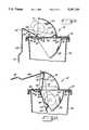
- FIG. 1is a perspective view of a top portion of a disposal system according to the invention, with one form of disposal container located within a hollow enclosure, and with the closure of the disposal container being fully opened,
- FIG. 2is a view similar to FIG. 1, but with the closure of the disposal container being partially closed,
- FIG. 3is a view similar to FIGS. 2 and 1, but with the closure for the disposal container being fully closed,
- FIG. 4is an enlarged partial cross sectional view through only the disposal container illustrated in FIG. 1, showing the closure being in the opened orientation and illustrating disposable sharps at various positions of disposal,
- FIG. 5is a cross sectional view of the closure of FIG. 4,
- FIG. 6is a view similar to FIG. 4, but with the closure being partially closed just prior to dropping a small disposed item within the container body,
- FIG. 7is a view similar to FIG. 6, but showing disposal of a larger sharps
- FIG. 8is a view similar to FIG. 6, but showing the closure fully rotated so that the disposed item drops within the container body
- FIG. 9is a view similar to FIG. 7, but showing the closure fully rotated so that the large disposed sharps drops within the container body
- FIG. 10is a view similar to FIGS. 8 and 9, but with the closure fully rotated to a locked orientation
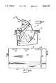
- FIG. 11is a cross sectional view similar to FIG. 4, but of a second embodiment of the invention, and showing a large sharp in phantom as it is placed upon the closure for disposal,
- FIG. 12is a view similar to FIG. 11, but with the closure partially closed, initially dropping the sharp to a second orientation within the container body,
- FIG. 13is a view similar to FIG. 12, but with the closure fully closed (but not locked), and showing the sharp dropping within the container body, and
- FIG. 14is a front elevational view of the closure of FIGS. 11-13.
- a sharps disposal systemis designated generally at 10 in the drawing figures.
- Primary components of the system 10are a hollow, outer enclosure 12 and an inner, disposal container 14 shaped to be located within the outer enclosure 12.
- the outer enclosure 12is illustrated only in FIGS. 1-3, it being evident that the inner disposal containers 14 illustrated in the ensuing drawing figures, although not illustrated in combination with an outer enclosure 12, are intended to fit within an outer enclosure in many, but not necessarily all, instances of use.
- the outer enclosure 12includes an access door 16 secured by one or more hinges 18 to a main body 20 of the enclosure 12.
- Both the outer enclosure 12 and the inner container 14are preferably made of various plastic materials, and if the inner container 14 is made of a translucent or transparent material, the door 16 can include a window 22 and the main body 20 can include one or more windows 24 for viewing the contents of the disposal container 14.
- One or more of the windows 22 and 24can include an indication 26 to show when the inner container 14 is sufficiently fully of sharps that it should be removed and emptied or replaced.
- the door 16includes some means for it to be locked to avoid tampering with the contents of the outer enclosure 12.
- other adjunct featurescan be incorporated into the outer enclosure 12, such as a glove dispenser as disclosed in U.S. Pat. No. 4,863,057. Any number of other features might be incorporated in the outer enclosure as desired.
- the inner disposal container 14is composed of a receptacle 28 and a top or cover 30 which is preferably snap-fitted onto the receptacle 28 in a conventional fashion. Other means of attachment can be employed as desired.
- the receptacle 28 and the cover 30are preferably formed of injection-molded plastic, and if the windows 22 and 24 are employed in the outer enclosure 12, it is preferred that at least the receptacle 28 be of translucent or transparent material so that the contents thereof can be viewed through the windows 22 and 24.
- the inner disposal container 14is shown being formed of two basic components, the receptacle 28 and the cover 30, it should be apparent that, depending on manufacturing capabilities and the desire of the user, the receptacle 28 might be formed of more than one piece, or the receptacle 28 and the cover 30 can be formed in an integral fashion.
- the cover 30includes several features. It has an integral cowl 32 extending over an opening 34 through the cover 30. The opening is provided for permitting access to the interior of the inner container 14, and the cowl 32 extends for the length and width of the opening 34. Also, as best shown in FIGS. 1-3, the cowl 32 is generally coextensive with a hood 36 formed in the outer enclosure 12. The cowl 32 forms a first constriction extending over the opening 34.
- the cover 30is provided with a second cowl 38 extending beneath the cover 30 as shown.
- the cowl 38forms a second constriction extending beneath the opening 34, and the cowls 32 and 38 form at least part of a barrier for restricting access by a user to the interior of the inner container 14.
- a pivotal closure 40is mounted in the cover 30 at one side of the opening 34.
- the closure 40extends for the length of the opening 34, and includes pivot pins 42 at opposite ends thereof, each of which extends into a pivot bracket 44 formed in the cover 30.
- Other means of pivotingcan be employed, as well.
- the closure 40has an inner portion 46 shaped to extend across the opening 34.
- the lower cowl 38is offset from the upper cowl 32, forming a longitudinal obstruction 48 extending between the opening 34 and the cowl 38.
- the closure 40also includes a terminal end 50 extending from the inner portion 46 and shaped to engage the obstruction 48.
- a heel 52is also formed in the closure 40 at the juncture of the inner portion 46 and the terminal end 50.
- the closure 40Opposite the pivot pins 42, the closure 40 includes an outer portion 54 forming a platform for receipt of sharps and also extending sufficiently to close a mouth 56 of the cowl 32, as best shown in FIGS. 8-10.
- the outer portion 54terminates at a flap 58 having a curvature sufficient to mate with the curvature of the cowl 32.
- the flap 58also has a grip 60 to allow the user to readily manipulate the closure 40 when using the disposal container 14.
- the closure 40pivots about a pivot axis extending through the opposite pivot pins 42.
- the terminal end 50extends to an up-turned tip 62 proximate the cowl 38.
- the curvature of the cowl 38is such that the tip 62 is always in close proximity to the cowl 38, and therefore preferably the cowl 38 is, at all points, radially equidistant from the pivot axis extending between the pins 42.
- the terminal end 50is downwardly offset from the inner portion 46.
- the obstruction 48is formed from an outward offsetting of the cowl 38 from the opening 34.
- the obstruction 48 and terminal end 50form a retention pocket or means 64 for preventing sharps from being dispensed through the opening 34 from the interior of the container 14 when the container is upright.
- the pocket 64occurs because the closure 40 butts against a shelf 66 formed in the cover 30. If the shelf 66 were not included (as is the case in the second embodiment of FIGS. 11-14), the terminal end 50 would essential mate with the obstruction 48, eliminating any retention pocket per se, but still providing the retention means, as explained further below.
- Meansis also provided for essentially permanently locking the closure 40 to prevent access to the interior of the container 14.
- At least one catch 68is provided in the cowl 32, in alignment with an engaging member 70 formed in the flap 58. When the closure 40 is fully rotated to the closed positioned shown in FIG. 10, the engaging member 70 engages behind the catch 68, preventing rotation of the closure 40 in the opposite direction.
- a used sharp 72, 74 or 76is placed on the outer portion 54 of the closure 40 when opened, typically one at a time.
- the userthen pivots the closure 40 upwardly in relation to the grip 60, causing the sharp to first fall into the container 14 and rest against the inner cowl 38. Further rotating of the closure then causes the used sharp to drop into the interior of the container 14.
- the closure 40cannot be reopened to inadvertently eject the sharp from the interior of the container 14. This is due to the downward offset of the terminal end 50 in combination with the lateral offset of the cowl 38. Once a sharp is in the position of the pocket 64, it is captured within the container 14, and cannot be ejected back through the opening 34. Rather, the closure 40 must continue to be pivoted until the sharp drops within the interior of the container 14.
- the closure 40is pivoted fully upright until the engaging member 70 engages behind the catch 68. The closure 40 is then essentially locked in place, and the container 14 can be disposed of appropriately.
- FIGS. 11-14A second embodiment of the inner disposal container is shown in FIGS. 11-14. While the container 14' is generally similar to, and shares common basic features of, the container 14, some differences exist, as well.
- the container 14'is composed of two basic portions, a receptacle 78 and a cover 80.
- the receptacle 78can be identical to the receptacle 28 of the first embodiment of the invention.
- the receptacle 78 and the cover 80may be joined in any fashion, as explained in connection with the first embodiment of the invention.
- the cover 80includes an upper cowl 82 extending above, and coextensive with, an opening 84 to the interior of the receptacle 78.
- a second, lower cowl 86extends beneath the cover 80 and opening 84, in precisely the same manner as the first embodiment of the invention.
- the cowl 86may be an integral extension of the cover 80, or, as illustrated, may include a peripheral flange 88 which is attached to the underside of the cover 80, such as on a series of pins 90.
- the cowl 86can be appropriately affixed to the underside of the cover 88 in any conventional manner as desired.
- a closure 92is pivotally mounted at one side of the opening 84.
- the closure 92includes opposite pivot pins 94 engaged in opposite sockets 96 formed in the cover 80. Therefore, the closure 92 pivots about a pivot axis extending through the opposite pivot pins 94.
- the closure 92includes an inner portion 98 shaped to close the opening 84.
- the inner portion 98includes a heel 100 which, as shown in FIG. 11, is shaped to engage the inner surface of the cowl 82.
- a terminal end 102extends from the inner portion 98, coextensive with an obstruction 104 formed by the offset of the cowl 86 from the opening 84.
- the heel 100, terminal end 102 and obstruction 104form a retention for preventing sharps from being dispensed through the opening 84 from the interior of the receptacle 78 in use, as explained in a bit greater detail below.
- the closure 92also includes an outer portion 106, with an activation flap 108 extending from an outer terminal edge of the outer portion 106.
- the flap 108extends to a grip 110 at a distal edge thereof.
- the closure 92is freely pivotal about its pivot pins 94.
- the flap 108 and grip 110are sized such that their combined mass biases the closure 92 in the opened orientation shown in FIG. 11.
- the flap 108 and grip 110counterweight the oppositely extending inner portion 98 and terminal end 102.
- the amount of material in the flap 108 and grip 110can be chosen judiciously so that the closure 92 allows automatic ejection of a sharp 72 when placed on the inner portion 98, as explained in greater detail.
- the cowl 82For permanent locking of the closure 92 when the receptacle 78 is filled with waste or when it is desired to be discarded, the cowl 82 includes at least one catch 112 extending downwardly and in alignment with a series of apertures 114 formed in the flap 108.
- the catch 112forms a stop which engages the aperture 114 when the flap 108 is pushed to engage the catch 112 in an aperture 114.
- a sharp 72 to be discarded within the container 14'is placed on the inner portion 98. If sufficiently massive, the weight of the sharp 72 causes the closure 92 to pivot as shown in the sequence of FIGS. 11-13, dropping the sharp 72 within the receptacle 78. If the sharp 72 does not have sufficient weight to overbalance the counterbalancing of the weight of the flap 108 and grip 110, the user can simply lift the flap 108 at the grip 110, causing the sharp 72 to fall within the receptacle 78 in exactly the same fashion as explained in connection with the first embodiment of FIGS. 1-10.
- the closure 92is locked by pushing the flap 108 until the catches 112 engage the apertures 114. The closure 92 is then locked in place.
- the useris prevented from reaching into the interior of the receptacle 78 due to the cooperation of the two cowls 82 and 86.
- the closure 92cooperates with the cowls 82 and 86 to serve as a further barrier to the interior of the receptacle 78. Only when the outer portion 106 is engaged beneath the cowl 82 does the terminal end 102 extend past the cowl 86. Therefore, the user is doubly protected from any means of inadvertently extending fingers within the receptacle 78.
Landscapes
- Health & Medical Sciences (AREA)
- Engineering & Computer Science (AREA)
- Surgery (AREA)
- Life Sciences & Earth Sciences (AREA)
- Molecular Biology (AREA)
- Biomedical Technology (AREA)
- Heart & Thoracic Surgery (AREA)
- Medical Informatics (AREA)
- Nuclear Medicine, Radiotherapy & Molecular Imaging (AREA)
- Animal Behavior & Ethology (AREA)
- General Health & Medical Sciences (AREA)
- Public Health (AREA)
- Veterinary Medicine (AREA)
- Mechanical Engineering (AREA)
- Refuse Receptacles (AREA)
- Accommodation For Nursing Or Treatment Tables (AREA)
Abstract
Description
This invention relates to disposal of contaminated items, and in particular to a disposal system for use in a hospital or similar environment where contaminated items must be collected and disposed of without creating a hazard for patients or hospital personnel.
In hospitals, clinics and similar medical institutions, contamination continues to be of utmost concern. With the prevention of the spread of communicable diseases being a major priority, disposable, single use patient-use care products have become quite prevalent. Those items, once used, are contaminated and can readily transmit disease. They include items such as hypodermic needles and other sharps, and are required to be disposed of at their point of usage under current guidelines of the United States Centers for Disease Control. In U.S. Pat. Re. No. 33,413, the disclosure of which is incorporated herein by reference, and U.S. Pat. No. 4,779,728, the disclosure of which is incorporated herein by reference, sharps disposal systems are described. The present invention is an improvement over those systems.
The invention provides a hollow, upstanding container body having an opening at the top of the container body for permitting access to the interior of the container body. A barrier is disposed proximate the opening for restricting access to the interior of the container body, at least a portion of the barrier comprising a first constriction extending over the opening and a second constriction extending beneath the opening. Retention means is provided for preventing -items from being dispensed through the opening from the interior of the container body when the container body is upright.
In accordance with the preferred form of the invention, the disposal container includes a closure disposed adjacent to the opening. The closure preferably is pivotal, and the retention means comprises the combination of two features of the invention, shaping of a portion of the closure to extend across the opening and positioning of the second constriction in an offset fashion relative to the opening. The second constriction comprises a cowl extending into the interior of the container body, the cowl being located at one longitudinal side of the opening and the closure being pivotally disposed at an opposite longitudinal side of the opening. The closure pivots about a longitudinal pivot axis, and the cowl is shaped to be radially equidistant from the pivot axis at all locations.
The offsetting of the second constriction from the first provides a longitudinal obstruction extending between the opening and the second constriction. The closure is provided with a terminal end which is shaped to engage that obstruction. Also, the closure is provided with a heel adjacent to the terminal end, with the heel being shaped to engage the first constriction when the terminal end engages the longitudinal obstruction.
The closure also includes a portion shaped to engage and close the first constriction. An activation flap extends from and is coextensive with a terminal edge of that portion to permit pivoting of the closure. The closure also includes means biasing the closure such that it normally remains in an opened orientation. Preferably, the biasing means is a counterweight, the flap including the counterweight as an integral portion thereof.
In accordance with the preferred forms of the invention, the first constriction includes means for locking the closure to prevent access to the interior of the container body when locked. To this end, within the cowl of the first constriction is included at least one catch. The catch includes a stop which engages the closure when the closure is pivoted in one direction past the stop into the interior of the cowl. At that orientation, the stop prevents pivoting of the closure in an opposite direction to reopen the container.
The disposal system according to the invention may include the disposal container as an inner container within a hollow, outer enclosure. The outer enclosure is shaped to accommodate and conform at least in part to the inner container. Preferably, the outer enclosure includes a hood, with the hood being shaped to conform to the first constriction and being located in registration with the constriction when the container is located within the outer enclosure.
The invention is described in greater detail in the following description of examples embodying the best mode of the invention, taken in conjunction with the drawings, in which:
FIG. 1 is a perspective view of a top portion of a disposal system according to the invention, with one form of disposal container located within a hollow enclosure, and with the closure of the disposal container being fully opened,
FIG. 2 is a view similar to FIG. 1, but with the closure of the disposal container being partially closed,
FIG. 3 is a view similar to FIGS. 2 and 1, but with the closure for the disposal container being fully closed,
FIG. 4 is an enlarged partial cross sectional view through only the disposal container illustrated in FIG. 1, showing the closure being in the opened orientation and illustrating disposable sharps at various positions of disposal,
FIG. 5 is a cross sectional view of the closure of FIG. 4,
FIG. 6 is a view similar to FIG. 4, but with the closure being partially closed just prior to dropping a small disposed item within the container body,
FIG. 7 is a view similar to FIG. 6, but showing disposal of a larger sharps,
FIG. 8 is a view similar to FIG. 6, but showing the closure fully rotated so that the disposed item drops within the container body,
FIG. 9 is a view similar to FIG. 7, but showing the closure fully rotated so that the large disposed sharps drops within the container body,
FIG. 10 is a view similar to FIGS. 8 and 9, but with the closure fully rotated to a locked orientation,
FIG. 11 is a cross sectional view similar to FIG. 4, but of a second embodiment of the invention, and showing a large sharp in phantom as it is placed upon the closure for disposal,
FIG. 12 is a view similar to FIG. 11, but with the closure partially closed, initially dropping the sharp to a second orientation within the container body,
FIG. 13 is a view similar to FIG. 12, but with the closure fully closed (but not locked), and showing the sharp dropping within the container body, and
FIG. 14 is a front elevational view of the closure of FIGS. 11-13.
A sharps disposal system according to the invention is designated generally at 10 in the drawing figures. Primary components of the system 10 are a hollow,outer enclosure 12 and an inner,disposal container 14 shaped to be located within theouter enclosure 12. Theouter enclosure 12 is illustrated only in FIGS. 1-3, it being evident that theinner disposal containers 14 illustrated in the ensuing drawing figures, although not illustrated in combination with anouter enclosure 12, are intended to fit within an outer enclosure in many, but not necessarily all, instances of use.
Theouter enclosure 12 includes anaccess door 16 secured by one ormore hinges 18 to amain body 20 of theenclosure 12. Both theouter enclosure 12 and theinner container 14 are preferably made of various plastic materials, and if theinner container 14 is made of a translucent or transparent material, thedoor 16 can include awindow 22 and themain body 20 can include one ormore windows 24 for viewing the contents of thedisposal container 14. One or more of thewindows indication 26 to show when theinner container 14 is sufficiently fully of sharps that it should be removed and emptied or replaced.
Other features of theouter enclosure 12 may be included as desired. For example, preferably thedoor 16 includes some means for it to be locked to avoid tampering with the contents of theouter enclosure 12. Also, other adjunct features can be incorporated into theouter enclosure 12, such as a glove dispenser as disclosed in U.S. Pat. No. 4,863,057. Any number of other features might be incorporated in the outer enclosure as desired.
Theinner disposal container 14 is composed of areceptacle 28 and a top orcover 30 which is preferably snap-fitted onto thereceptacle 28 in a conventional fashion. Other means of attachment can be employed as desired. Thereceptacle 28 and thecover 30 are preferably formed of injection-molded plastic, and if thewindows outer enclosure 12, it is preferred that at least thereceptacle 28 be of translucent or transparent material so that the contents thereof can be viewed through thewindows inner disposal container 14 is shown being formed of two basic components, thereceptacle 28 and thecover 30, it should be apparent that, depending on manufacturing capabilities and the desire of the user, thereceptacle 28 might be formed of more than one piece, or thereceptacle 28 and thecover 30 can be formed in an integral fashion.
Thecover 30 includes several features. It has anintegral cowl 32 extending over anopening 34 through thecover 30. The opening is provided for permitting access to the interior of theinner container 14, and thecowl 32 extends for the length and width of theopening 34. Also, as best shown in FIGS. 1-3, thecowl 32 is generally coextensive with ahood 36 formed in theouter enclosure 12. Thecowl 32 forms a first constriction extending over theopening 34.
Thecover 30 is provided with asecond cowl 38 extending beneath thecover 30 as shown. Thecowl 38 forms a second constriction extending beneath theopening 34, and thecowls inner container 14.
Apivotal closure 40 is mounted in thecover 30 at one side of theopening 34. Theclosure 40 extends for the length of theopening 34, and includes pivot pins 42 at opposite ends thereof, each of which extends into apivot bracket 44 formed in thecover 30. Other means of pivoting can be employed, as well.
Theclosure 40 has aninner portion 46 shaped to extend across theopening 34. Thelower cowl 38 is offset from theupper cowl 32, forming alongitudinal obstruction 48 extending between theopening 34 and thecowl 38. Theclosure 40 also includes aterminal end 50 extending from theinner portion 46 and shaped to engage theobstruction 48. Aheel 52 is also formed in theclosure 40 at the juncture of theinner portion 46 and theterminal end 50.
Opposite the pivot pins 42, theclosure 40 includes anouter portion 54 forming a platform for receipt of sharps and also extending sufficiently to close amouth 56 of thecowl 32, as best shown in FIGS. 8-10.
Theouter portion 54 terminates at aflap 58 having a curvature sufficient to mate with the curvature of thecowl 32. Theflap 58 also has agrip 60 to allow the user to readily manipulate theclosure 40 when using thedisposal container 14.
Theclosure 40 pivots about a pivot axis extending through the opposite pivot pins 42. Theterminal end 50 extends to an up-turnedtip 62 proximate thecowl 38. The curvature of thecowl 38 is such that thetip 62 is always in close proximity to thecowl 38, and therefore preferably thecowl 38 is, at all points, radially equidistant from the pivot axis extending between thepins 42.
Theterminal end 50 is downwardly offset from theinner portion 46. Theobstruction 48 is formed from an outward offsetting of thecowl 38 from theopening 34. Theobstruction 48 andterminal end 50 form a retention pocket or means 64 for preventing sharps from being dispensed through the opening 34 from the interior of thecontainer 14 when the container is upright. Thepocket 64 occurs because theclosure 40 butts against ashelf 66 formed in thecover 30. If theshelf 66 were not included (as is the case in the second embodiment of FIGS. 11-14), theterminal end 50 would essential mate with theobstruction 48, eliminating any retention pocket per se, but still providing the retention means, as explained further below.
Means is also provided for essentially permanently locking theclosure 40 to prevent access to the interior of thecontainer 14. At least onecatch 68 is provided in thecowl 32, in alignment with an engagingmember 70 formed in theflap 58. When theclosure 40 is fully rotated to the closed positioned shown in FIG. 10, the engagingmember 70 engages behind thecatch 68, preventing rotation of theclosure 40 in the opposite direction.
In use, as shown in FIGS. 4-8, a used sharp 72, 74 or 76 is placed on theouter portion 54 of theclosure 40 when opened, typically one at a time. The user then pivots theclosure 40 upwardly in relation to thegrip 60, causing the sharp to first fall into thecontainer 14 and rest against theinner cowl 38. Further rotating of the closure then causes the used sharp to drop into the interior of thecontainer 14.
During the disposal process, once a sharp 70-76 has fallen sufficiently into thecontainer 14 that it abuts thecowl 38, theclosure 40 cannot be reopened to inadvertently eject the sharp from the interior of thecontainer 14. This is due to the downward offset of theterminal end 50 in combination with the lateral offset of thecowl 38. Once a sharp is in the position of thepocket 64, it is captured within thecontainer 14, and cannot be ejected back through theopening 34. Rather, theclosure 40 must continue to be pivoted until the sharp drops within the interior of thecontainer 14.
This phenomenon is first demonstrated with the relatively large sharp 72. As shown in FIG. 4, when the sharp 72 is to be disposed, it is placed on theclosure 40 and, although not illustrated, due to the inclination of theclosure 40, normally slides or rolls until it abuts thecowl 32 above theinner portion 46. Then, as shown in FIG. 7, theclosure 40 is pivoted, causing the sharp 72 to fall until it abuts thecowl 38. At this position, theclosure 40 cannot be pivoted in the opposite direction, since the sharp 72 is lodged between theobstruction 48 and either theterminal end 50 or the heel 52 (or both). The user must further rotate theclosure 40, as shown in FIG. 9, until the sharp 72 drops within the interior of thecontainer 14.
Similar results occur withsmaller sharps pocket 64, it cannot be ejected since it is captured between theterminal end 50 and theobstruction 48. Rather, in order to release the sharp 74 or 76, the closure must be pivoted as shown in FIGS. 6 and 8 until the sharp drops within the interior of thecontainer 14.
Once thereceptacle 28 has been filled or if it is desired to remove a partially filledcontainer 14 from theouter enclosure 12, as shown in FIG. 10, theclosure 40 is pivoted fully upright until the engagingmember 70 engages behind thecatch 68. Theclosure 40 is then essentially locked in place, and thecontainer 14 can be disposed of appropriately.
A second embodiment of the inner disposal container is shown in FIGS. 11-14. While the container 14' is generally similar to, and shares common basic features of, thecontainer 14, some differences exist, as well.
The container 14' is composed of two basic portions, areceptacle 78 and acover 80. Thereceptacle 78 can be identical to thereceptacle 28 of the first embodiment of the invention. Thereceptacle 78 and thecover 80 may be joined in any fashion, as explained in connection with the first embodiment of the invention.
Thecover 80 includes anupper cowl 82 extending above, and coextensive with, anopening 84 to the interior of thereceptacle 78. A second,lower cowl 86 extends beneath thecover 80 andopening 84, in precisely the same manner as the first embodiment of the invention. Thecowl 86 may be an integral extension of thecover 80, or, as illustrated, may include aperipheral flange 88 which is attached to the underside of thecover 80, such as on a series ofpins 90. Thecowl 86 can be appropriately affixed to the underside of thecover 88 in any conventional manner as desired.
Aclosure 92 is pivotally mounted at one side of theopening 84. Theclosure 92 includes opposite pivot pins 94 engaged inopposite sockets 96 formed in thecover 80. Therefore, theclosure 92 pivots about a pivot axis extending through the opposite pivot pins 94.
Theclosure 92 includes aninner portion 98 shaped to close theopening 84. Theinner portion 98 includes aheel 100 which, as shown in FIG. 11, is shaped to engage the inner surface of thecowl 82. Aterminal end 102 extends from theinner portion 98, coextensive with anobstruction 104 formed by the offset of thecowl 86 from theopening 84. Theheel 100,terminal end 102 andobstruction 104 form a retention for preventing sharps from being dispensed through the opening 84 from the interior of thereceptacle 78 in use, as explained in a bit greater detail below.
Theclosure 92 also includes anouter portion 106, with anactivation flap 108 extending from an outer terminal edge of theouter portion 106. Theflap 108 extends to agrip 110 at a distal edge thereof.
Theclosure 92 is freely pivotal about its pivot pins 94. Preferably, theflap 108 andgrip 110 are sized such that their combined mass biases theclosure 92 in the opened orientation shown in FIG. 11. Theflap 108 andgrip 110 counterweight the oppositely extendinginner portion 98 andterminal end 102. The amount of material in theflap 108 andgrip 110 can be chosen judiciously so that theclosure 92 allows automatic ejection of a sharp 72 when placed on theinner portion 98, as explained in greater detail.
For permanent locking of theclosure 92 when thereceptacle 78 is filled with waste or when it is desired to be discarded, thecowl 82 includes at least onecatch 112 extending downwardly and in alignment with a series ofapertures 114 formed in theflap 108. Thecatch 112 forms a stop which engages theaperture 114 when theflap 108 is pushed to engage thecatch 112 in anaperture 114.
In use, a sharp 72 to be discarded within the container 14' is placed on theinner portion 98. If sufficiently massive, the weight of the sharp 72 causes theclosure 92 to pivot as shown in the sequence of FIGS. 11-13, dropping the sharp 72 within thereceptacle 78. If the sharp 72 does not have sufficient weight to overbalance the counterbalancing of the weight of theflap 108 andgrip 110, the user can simply lift theflap 108 at thegrip 110, causing the sharp 72 to fall within thereceptacle 78 in exactly the same fashion as explained in connection with the first embodiment of FIGS. 1-10. Also, due to the offset forming theobstruction 104, in combination with theheel 100 andterminal end 102, once a sharp 72 engages thelower cowl 86, it is captured, and cannot be returned through theopening 84 if the rotational direction of theclosure 92 is reversed.
Once thereceptacle 78 is filled or desired to be discarded, theclosure 92 is locked by pushing theflap 108 until thecatches 112 engage theapertures 114. Theclosure 92 is then locked in place.
In this form of the invention, the user is prevented from reaching into the interior of thereceptacle 78 due to the cooperation of the twocowls closure 92 cooperates with thecowls receptacle 78. Only when theouter portion 106 is engaged beneath thecowl 82 does theterminal end 102 extend past thecowl 86. Therefore, the user is doubly protected from any means of inadvertently extending fingers within thereceptacle 78.
Various changes can be made to the invention without departing from the spirit thereof or scope of the following claims.
Claims (19)
1. A disposal container comprising
a. a hollow, upstanding container body,
b. an opening at the top of the container body for permitting access to the interior of the container body,
c. barrier means disposed proximate said opening for restricting access to the interior of said container body, at least a portion of said barrier means comprising
i. a first constriction extending over said opening, and
ii. a second constriction extending beneath said opening, said second constriction being offset from said first constriction forming an obstruction in the top of said container body, and
d. retention means for preventing items from being dispensed through said opening from the interior of the container body when said container body is upright, at least a portion of said retention means comprising said obstruction.
2. A disposal container according to claim 1 including a closure disposed adjacent said opening.
3. A disposal container according to claim 2 in which said closure is pivotal, and in which said retention means comprises the combination of a portion of said closure shaped to extend across said opening and said obstruction.
4. A disposal container according to claim 3 in which said second constriction comprises a cowl extending into the interior of the container body, said cowl being located at one longitudinal side of said opening and said closure being pivotally disposed at an opposite longitudinal side of said opening.
5. A disposal container according to claim 4 in which said closure pivots about a longitudinal pivot axis, said cowl being radially equidistant from said pivot axis.
6. A disposal container according to claim 3 in which said obstruction extends between said opening and said second constriction, said closure portion having a terminal end shaped to engage said obstruction.
7. A disposal container according to claim 6 including a heel in said closure portion adjacent said terminal end, said heel being shaped to engage said first constriction when said terminal end engages said obstruction.
8. A disposal container according to claim 2 in which said closure is pivotally mounted about a longitudinal pivot axis, said closure comprising a first portion shaped to engage and close said first constriction and a second portion shaped to extend across said opening.
9. A disposal container according to claim 8 including an activation flap extending from and coextensive with a terminal edge of said first portion.
10. A disposal container according to claim 9 in which said closure includes means biasing said closure with said second portion extending across said opening.
11. A disposal container according to claim 10 in which said biasing means comprises a counterweight.
12. A disposal container according to claim 11 in which said counterweight comprises said flap.
13. A disposal container according to claim 2 in which said closure is pivotal, and said first constriction includes means for locking said closure to prevent access to the interior of said container body.
14. A disposal container according to claim 13 in which said first constriction comprises a cowl extending from and above a longitudinal side of said opening, and said locking means comprises at least one catch within said cowl, each said catch including a stop engaging said closure when said closure is pivoted in one direction past said stop into the interior of said cowl, said stop preventing pivoting of said closure in an opposite direction.
15. A disposal container according to claim 1 in which said first constriction comprises a first cowl extending from and above a longitudinal side of said opening and said second constriction comprises a second cowl extending from and beneath said longitudinal side.
16. A disposal system comprising
a. an inner disposal container having a hollow upstanding container body,
b. an opening at the top of the container body for permitting access to the interior of the container body,
c. barrier means disposed proximate said opening for restricting access to the interior of said container body, at least a portion of said barrier means comprising
i. a first constriction extending over said opening, and
ii. a second constriction extending beneath said opening,
d. retention means for preventing items from being dispensed through said opening from the interior of the container body when said container body is upright, and
e. a hollow, outer enclosure shaped to accommodate said inner container, said inner container being removable from said outer enclosure.
17. A disposal system according to claim 16 in which said outer enclosure includes a hood, said hood being shaped to conform to said first constriction and being located in registration with said first constriction when said inner container is located within said outer enclosure.
18. A disposal system according to claim 16 including a closure disposed adjacent said opening.
19. A disposal system according to claim 18 in which said closure is pivotal, and in which said retention means comprises the combination of a portion of said closure shaped to extend across said opening and positioning of said second constriction in an offset fashion relative to said opening.
Priority Applications (2)
| Application Number | Priority Date | Filing Date | Title |
|---|---|---|---|
| US08/044,590US5387735A (en) | 1993-04-08 | 1993-04-08 | Sharps disposal container and system |
| CA002114987ACA2114987C (en) | 1993-04-08 | 1994-02-04 | Sharps disposal container and system |
Applications Claiming Priority (1)
| Application Number | Priority Date | Filing Date | Title |
|---|---|---|---|
| US08/044,590US5387735A (en) | 1993-04-08 | 1993-04-08 | Sharps disposal container and system |
Publications (1)
| Publication Number | Publication Date |
|---|---|
| US5387735Atrue US5387735A (en) | 1995-02-07 |
Family
ID=21933200
Family Applications (1)
| Application Number | Title | Priority Date | Filing Date |
|---|---|---|---|
| US08/044,590Expired - LifetimeUS5387735A (en) | 1993-04-08 | 1993-04-08 | Sharps disposal container and system |
Country Status (2)
| Country | Link |
|---|---|
| US (1) | US5387735A (en) |
| CA (1) | CA2114987C (en) |
Cited By (42)
| Publication number | Priority date | Publication date | Assignee | Title |
|---|---|---|---|---|
| USD385349S (en)* | 1995-10-05 | 1997-10-21 | Sage Products, Inc. | Enclosure for a needle disposal container |
| USD385626S (en)* | 1995-10-05 | 1997-10-28 | Sage Products, Inc. | Combined enclosure for a needle disposal container and glove dispenser |
| EP0842641A1 (en) | 1996-11-15 | 1998-05-20 | Graphic Controls Corporation | Medical waste disposal container |
| US5848692A (en)* | 1997-06-18 | 1998-12-15 | Specialized Health Products, Inc. | Unimold container for discarding medical material |
| USD411008S (en)* | 1997-11-07 | 1999-06-15 | Graphic Controls Corporation | Cabinet for housing a medical waste container |
| USD414864S (en) | 1998-05-28 | 1999-10-05 | Graphic Controls Corporation | Combined cabinet and container for housing medical waste |
| USD415273S (en)* | 1998-05-28 | 1999-10-12 | Graphic Controls Corporation | Combined cabinet with glove box and container for housing medical waste |
| US5967317A (en)* | 1998-08-05 | 1999-10-19 | Wright; Alan | Syringe orienting disposable container |
| EP0861597A3 (en)* | 1997-02-26 | 1999-11-03 | Ali S.p.A. | Feed device for use in machines for processing pasty or liquid food mixtures |
| USD421122S (en)* | 1998-05-28 | 2000-02-22 | Graphic Controls Corporation | Medical waste container |
| US6062001A (en)* | 1999-08-02 | 2000-05-16 | Sharps Compliance, Inc. | Sharps disposal container |
| US6082574A (en)* | 1998-09-03 | 2000-07-04 | Johnson; Samuel V. | Collection apparatus |
| EP1001820A4 (en)* | 1998-05-15 | 2000-07-19 | Catilina Nominees Pty Ltd | Sharps container |
| USD438964S1 (en) | 1997-11-07 | 2001-03-13 | Graphic Controls Corporation | Cabinet and container for housing medical waste |
| US6283909B1 (en) | 1999-01-22 | 2001-09-04 | Fraser R. Sharp | Container for supplying medical products and disposal of medical waste material |
| USD451195S1 (en) | 1999-11-09 | 2001-11-27 | Catalina Nominees | Set of sharps containers |
| US6364147B1 (en) | 2001-05-04 | 2002-04-02 | Creative Bath Products, Inc | Waste can with concealed waste bag and swing-open lid |
| USD461940S1 (en) | 2001-05-04 | 2002-08-20 | Creative Bath Products, Inc. | Waste receptacle |
| USD478664S1 (en) | 2002-05-17 | 2003-08-19 | Sherwood Services Ag | Sharps container |
| USD478663S1 (en) | 2002-05-17 | 2003-08-19 | Sherwood Services Ag | Enclosure for a sharps container |
| US6626318B2 (en)* | 1999-04-07 | 2003-09-30 | Ignacio Ramirez Salcedo | Trash dump with safety collector |
| US20030213714A1 (en)* | 2002-05-17 | 2003-11-20 | Moats Donna L. | Low profile sharps container system |
| FR2867169A1 (en)* | 2004-03-04 | 2005-09-09 | Pierre Chretien | Wastebin access prohibiting device for use in hospital medium, has basin equipped at its upper part with specific cover which is provided with openings, hood covering openings with limited passage, and baffle provided on cover |
| US20060219718A1 (en)* | 2005-04-05 | 2006-10-05 | Sherwood Services, Ag | Integral tortuous path receptacle cover |
| USD531309S1 (en) | 2004-11-19 | 2006-10-31 | Deroyal Industries, Inc. | Portion of a sharps container |
| US20070068832A1 (en)* | 2005-09-27 | 2007-03-29 | Anderson T N | Method and apparatus for collecting sharps |
| US20070068831A1 (en)* | 2005-09-27 | 2007-03-29 | Klein Ronald T | Method and apparatus for collecting sharps |
| US20070068834A1 (en)* | 2005-09-27 | 2007-03-29 | Smudde Anton M | Method and apparatus for collecting sharps |
| US20070068833A1 (en)* | 2005-09-27 | 2007-03-29 | Smudde Anton M | Method and apparatus for collecting sharps |
| US20070080223A1 (en)* | 2005-10-07 | 2007-04-12 | Sherwood Services Ag | Remote monitoring of medical device |
| US20080023475A1 (en)* | 2006-07-27 | 2008-01-31 | Helen Of Troy Limited | Trash can assembly |
| US20090272677A1 (en)* | 2003-09-19 | 2009-11-05 | Vesta Medical, Llc | Automated waste sorting system |
| US20110031144A1 (en)* | 2009-08-06 | 2011-02-10 | John Allegretti | Wall mountable retainer for medical sharps |
| US7971715B1 (en) | 2004-11-15 | 2011-07-05 | Deroyal Industries, Inc. | Medical disposables containers |
| US20120067753A1 (en)* | 2010-09-22 | 2012-03-22 | Derick Foster | Sharps container |
| CN101229873B (en)* | 2007-01-26 | 2012-04-11 | 卡达莲娜·罗末丽有限公司 | Storage bin for disposing medical sharp device and waste |
| US20120228303A1 (en)* | 2011-03-09 | 2012-09-13 | Yamaguchi Car - Material Co., Ltd. | Bag and container for collecting recyclable garbage |
| JP2013535994A (en)* | 2010-07-06 | 2013-09-19 | ベクトン・ディキンソン・アンド・カンパニー | Sharp container |
| DE102012206239A1 (en)* | 2012-04-17 | 2013-10-17 | Hamilton Bonaduz Ag | Dosing device, in particular automatic pipetting with disposal container |
| US20150060449A1 (en)* | 2013-09-03 | 2015-03-05 | Christopher R. Brooks | Pharmaceutical waste container and lid |
| US8998031B2 (en)* | 2011-08-26 | 2015-04-07 | Stericycle, Inc. | Waste container assembly |
| US10321968B2 (en) | 2015-10-23 | 2019-06-18 | Medline Industries, Inc. | Sharps container |
Citations (4)
| Publication number | Priority date | Publication date | Assignee | Title |
|---|---|---|---|---|
| US4890733A (en)* | 1988-03-01 | 1990-01-02 | Anderson Robert S | Disposal receptacle for used, sharp, medical instruments or other biohazards |
| US4903832A (en)* | 1989-01-19 | 1990-02-27 | Winfield Corporation | Method and apparatus for cleanly storing and disposing of discarded articles |
| US5076429A (en)* | 1989-11-28 | 1991-12-31 | Voluntary Hospitals Of America | Sharps container |
| US5178322A (en)* | 1989-12-05 | 1993-01-12 | Med-Safe Systems, Inc. | Multiple configuration disposable sharps container system |
- 1993
- 1993-04-08USUS08/044,590patent/US5387735A/ennot_activeExpired - Lifetime
- 1994
- 1994-02-04CACA002114987Apatent/CA2114987C/ennot_activeExpired - Lifetime
Patent Citations (4)
| Publication number | Priority date | Publication date | Assignee | Title |
|---|---|---|---|---|
| US4890733A (en)* | 1988-03-01 | 1990-01-02 | Anderson Robert S | Disposal receptacle for used, sharp, medical instruments or other biohazards |
| US4903832A (en)* | 1989-01-19 | 1990-02-27 | Winfield Corporation | Method and apparatus for cleanly storing and disposing of discarded articles |
| US5076429A (en)* | 1989-11-28 | 1991-12-31 | Voluntary Hospitals Of America | Sharps container |
| US5178322A (en)* | 1989-12-05 | 1993-01-12 | Med-Safe Systems, Inc. | Multiple configuration disposable sharps container system |
Cited By (61)
| Publication number | Priority date | Publication date | Assignee | Title |
|---|---|---|---|---|
| USD385626S (en)* | 1995-10-05 | 1997-10-28 | Sage Products, Inc. | Combined enclosure for a needle disposal container and glove dispenser |
| USD385349S (en)* | 1995-10-05 | 1997-10-21 | Sage Products, Inc. | Enclosure for a needle disposal container |
| US5947285A (en)* | 1996-11-15 | 1999-09-07 | Graphic Controls Corporation | Medical waste disposal container |
| EP0842641A1 (en) | 1996-11-15 | 1998-05-20 | Graphic Controls Corporation | Medical waste disposal container |
| EP1609432A1 (en) | 1996-11-15 | 2005-12-28 | Graphic Controls Corporation | Medical waste disposal container |
| EP0861597A3 (en)* | 1997-02-26 | 1999-11-03 | Ali S.p.A. | Feed device for use in machines for processing pasty or liquid food mixtures |
| US6158331A (en)* | 1997-02-26 | 2000-12-12 | Ali S.P.A. | Feed device for pasty or liquid food mixtures |
| US5848692A (en)* | 1997-06-18 | 1998-12-15 | Specialized Health Products, Inc. | Unimold container for discarding medical material |
| USD411008S (en)* | 1997-11-07 | 1999-06-15 | Graphic Controls Corporation | Cabinet for housing a medical waste container |
| USD438964S1 (en) | 1997-11-07 | 2001-03-13 | Graphic Controls Corporation | Cabinet and container for housing medical waste |
| EP1001820A4 (en)* | 1998-05-15 | 2000-07-19 | Catilina Nominees Pty Ltd | Sharps container |
| US6250465B1 (en) | 1998-05-15 | 2001-06-26 | Catalina Nominees Pty. Ltd. | Sharps container |
| USD414864S (en) | 1998-05-28 | 1999-10-05 | Graphic Controls Corporation | Combined cabinet and container for housing medical waste |
| USD421122S (en)* | 1998-05-28 | 2000-02-22 | Graphic Controls Corporation | Medical waste container |
| USD415273S (en)* | 1998-05-28 | 1999-10-12 | Graphic Controls Corporation | Combined cabinet with glove box and container for housing medical waste |
| US5967317A (en)* | 1998-08-05 | 1999-10-19 | Wright; Alan | Syringe orienting disposable container |
| US6082574A (en)* | 1998-09-03 | 2000-07-04 | Johnson; Samuel V. | Collection apparatus |
| US6283909B1 (en) | 1999-01-22 | 2001-09-04 | Fraser R. Sharp | Container for supplying medical products and disposal of medical waste material |
| US6626318B2 (en)* | 1999-04-07 | 2003-09-30 | Ignacio Ramirez Salcedo | Trash dump with safety collector |
| US6062001A (en)* | 1999-08-02 | 2000-05-16 | Sharps Compliance, Inc. | Sharps disposal container |
| USD451195S1 (en) | 1999-11-09 | 2001-11-27 | Catalina Nominees | Set of sharps containers |
| USD461940S1 (en) | 2001-05-04 | 2002-08-20 | Creative Bath Products, Inc. | Waste receptacle |
| US6364147B1 (en) | 2001-05-04 | 2002-04-02 | Creative Bath Products, Inc | Waste can with concealed waste bag and swing-open lid |
| USD478664S1 (en) | 2002-05-17 | 2003-08-19 | Sherwood Services Ag | Sharps container |
| USD478663S1 (en) | 2002-05-17 | 2003-08-19 | Sherwood Services Ag | Enclosure for a sharps container |
| US20030213714A1 (en)* | 2002-05-17 | 2003-11-20 | Moats Donna L. | Low profile sharps container system |
| WO2003096921A3 (en)* | 2002-05-17 | 2004-05-06 | Sherwood Serv Ag | Low profile sharps container system |
| AU2003237854B2 (en)* | 2002-05-17 | 2008-05-01 | Cardinal Health 529, Llc | Low profile sharps container system |
| US8560460B2 (en)* | 2003-09-19 | 2013-10-15 | Carefusion 303, Inc. | Automated waste sorting system |
| US20150034534A1 (en)* | 2003-09-19 | 2015-02-05 | Carefusion 303, Inc. | Restricted access waste sorting system |
| US20090272677A1 (en)* | 2003-09-19 | 2009-11-05 | Vesta Medical, Llc | Automated waste sorting system |
| FR2867169A1 (en)* | 2004-03-04 | 2005-09-09 | Pierre Chretien | Wastebin access prohibiting device for use in hospital medium, has basin equipped at its upper part with specific cover which is provided with openings, hood covering openings with limited passage, and baffle provided on cover |
| US7971715B1 (en) | 2004-11-15 | 2011-07-05 | Deroyal Industries, Inc. | Medical disposables containers |
| USD531309S1 (en) | 2004-11-19 | 2006-10-31 | Deroyal Industries, Inc. | Portion of a sharps container |
| US20060219718A1 (en)* | 2005-04-05 | 2006-10-05 | Sherwood Services, Ag | Integral tortuous path receptacle cover |
| US8727162B2 (en) | 2005-04-05 | 2014-05-20 | Covidien Ag | Integral tortuous path receptacle cover |
| US20090289064A1 (en)* | 2005-04-05 | 2009-11-26 | Finnestad M Brian | Integral tortuous path receptacle cover |
| US20070068832A1 (en)* | 2005-09-27 | 2007-03-29 | Anderson T N | Method and apparatus for collecting sharps |
| US20070068831A1 (en)* | 2005-09-27 | 2007-03-29 | Klein Ronald T | Method and apparatus for collecting sharps |
| US7789230B2 (en)* | 2005-09-27 | 2010-09-07 | Covidien Ag | Method and apparatus for collecting sharps |
| US8875881B2 (en) | 2005-09-27 | 2014-11-04 | Covidien Ag | Method and apparatus for collecting sharps |
| US20070068834A1 (en)* | 2005-09-27 | 2007-03-29 | Smudde Anton M | Method and apparatus for collecting sharps |
| US8584850B2 (en)* | 2005-09-27 | 2013-11-19 | Covidien Ag | Apparatus for collecting sharps |
| US20070068833A1 (en)* | 2005-09-27 | 2007-03-29 | Smudde Anton M | Method and apparatus for collecting sharps |
| US20070080223A1 (en)* | 2005-10-07 | 2007-04-12 | Sherwood Services Ag | Remote monitoring of medical device |
| US20080023475A1 (en)* | 2006-07-27 | 2008-01-31 | Helen Of Troy Limited | Trash can assembly |
| CN101229873B (en)* | 2007-01-26 | 2012-04-11 | 卡达莲娜·罗末丽有限公司 | Storage bin for disposing medical sharp device and waste |
| US20110031144A1 (en)* | 2009-08-06 | 2011-02-10 | John Allegretti | Wall mountable retainer for medical sharps |
| US8783494B2 (en)* | 2010-07-06 | 2014-07-22 | Becton, Dickinson And Company | Sharps container |
| JP2013535994A (en)* | 2010-07-06 | 2013-09-19 | ベクトン・ディキンソン・アンド・カンパニー | Sharp container |
| US8893884B2 (en)* | 2010-09-22 | 2014-11-25 | Rehrig Pacific Company | Sharps container |
| US20120067753A1 (en)* | 2010-09-22 | 2012-03-22 | Derick Foster | Sharps container |
| US20120228303A1 (en)* | 2011-03-09 | 2012-09-13 | Yamaguchi Car - Material Co., Ltd. | Bag and container for collecting recyclable garbage |
| US8998031B2 (en)* | 2011-08-26 | 2015-04-07 | Stericycle, Inc. | Waste container assembly |
| US9585719B2 (en) | 2011-08-26 | 2017-03-07 | Stericycle, Inc. | Waste container assembly |
| DE102012206239A1 (en)* | 2012-04-17 | 2013-10-17 | Hamilton Bonaduz Ag | Dosing device, in particular automatic pipetting with disposal container |
| US20150060449A1 (en)* | 2013-09-03 | 2015-03-05 | Christopher R. Brooks | Pharmaceutical waste container and lid |
| US9511913B2 (en)* | 2013-09-03 | 2016-12-06 | Christopher R. Brooks | Pharmaceutical waste container and lid |
| US10321968B2 (en) | 2015-10-23 | 2019-06-18 | Medline Industries, Inc. | Sharps container |
| US11559369B2 (en) | 2015-10-23 | 2023-01-24 | Medline Industries, Lp | Sharps container |
| US12082951B2 (en) | 2015-10-23 | 2024-09-10 | Medine Industries, LP | Sharps container |
Also Published As
| Publication number | Publication date |
|---|---|
| CA2114987C (en) | 1998-04-21 |
| CA2114987A1 (en) | 1994-10-09 |
Similar Documents
| Publication | Publication Date | Title |
|---|---|---|
| US5387735A (en) | Sharps disposal container and system | |
| US5947285A (en) | Medical waste disposal container | |
| US5080251A (en) | Tortuous path in-patient room medical waste disposal container | |
| EP1001820B1 (en) | Sharps container | |
| US4903832A (en) | Method and apparatus for cleanly storing and disposing of discarded articles | |
| US4453648A (en) | Disposal bin | |
| EP1143868B1 (en) | Container for supplying medical products and disposal of medical waste material | |
| AU642974B2 (en) | Disposable sharp instrument container | |
| US8162139B2 (en) | Sharps disposal system | |
| US5647502A (en) | Wall mounted medical waste disposal container with pivoted top closure lid | |
| US5570783A (en) | Apparatus and methods for transporting and discarding medical materials | |
| CA1304054C (en) | Disposable container for syringes | |
| US5154345A (en) | Secure container for disposable sharps | |
| US4955477A (en) | Receptacle for storage and disposal of potentially injurious implements such as used scalpel blades, hypodermic needles and the like | |
| US4869366A (en) | Receptacle assembly for storage and disposal of potentially injurious implements such as used scalpel blades, hypodermic needles and the like | |
| US12082951B2 (en) | Sharps container | |
| GB2087360A (en) | Disposal Bin | |
| JP5873082B2 (en) | Sharp container | |
| EP0221378B1 (en) | Containers | |
| EP0431879B1 (en) | A secure container for disposable sharps | |
| AU747319B2 (en) | Sharps container | |
| JPH0767461B2 (en) | Waste tool | |
| HK1027766B (en) | Sharps container | |
| GB2442570A (en) | Sharps container with handle connected closure |
Legal Events
| Date | Code | Title | Description |
|---|---|---|---|
| AS | Assignment | Owner name:SAGE PRODUCTS, INC., ILLINOIS Free format text:ASSIGNMENT OF ASSIGNORS INTEREST.;ASSIGNORS:PONSI, LAWRENCE G.;SKIBA, BARBARA T.;MCDONOUGH, DAVID;REEL/FRAME:006521/0424 Effective date:19930407 | |
| STPP | Information on status: patent application and granting procedure in general | Free format text:APPLICATION UNDERGOING PREEXAM PROCESSING | |
| FEPP | Fee payment procedure | Free format text:PAYOR NUMBER ASSIGNED (ORIGINAL EVENT CODE: ASPN); ENTITY STATUS OF PATENT OWNER: LARGE ENTITY | |
| FPAY | Fee payment | Year of fee payment:4 | |
| AS | Assignment | Owner name:SHERWOOD SERVICES AG, SWITZERLAND Free format text:ASSIGNMENT OF ASSIGNORS INTEREST;ASSIGNOR:SAGE PRODUCTS, INC.;REEL/FRAME:012520/0609 Effective date:19991105 | |
| FPAY | Fee payment | Year of fee payment:8 | |
| FPAY | Fee payment | Year of fee payment:12 | |
| AS | Assignment | Owner name:COVIDIEN AG, SWITZERLAND Free format text:CHANGE OF NAME;ASSIGNOR:SHERWOOD SERVICES AG;REEL/FRAME:021371/0142 Effective date:20070309 |