US5387185A - Knee immobilizer splint - Google Patents
Knee immobilizer splintDownload PDFInfo
- Publication number
- US5387185A US5387185AUS08/148,937US14893793AUS5387185AUS 5387185 AUS5387185 AUS 5387185AUS 14893793 AUS14893793 AUS 14893793AUS 5387185 AUS5387185 AUS 5387185A
- Authority
- US
- United States
- Prior art keywords
- spine
- knee
- leg
- splint
- frame
- Prior art date
- Legal status (The legal status is an assumption and is not a legal conclusion. Google has not performed a legal analysis and makes no representation as to the accuracy of the status listed.)
- Expired - Lifetime
Links
Images


Classifications
- A—HUMAN NECESSITIES
- A61—MEDICAL OR VETERINARY SCIENCE; HYGIENE
- A61F—FILTERS IMPLANTABLE INTO BLOOD VESSELS; PROSTHESES; DEVICES PROVIDING PATENCY TO, OR PREVENTING COLLAPSING OF, TUBULAR STRUCTURES OF THE BODY, e.g. STENTS; ORTHOPAEDIC, NURSING OR CONTRACEPTIVE DEVICES; FOMENTATION; TREATMENT OR PROTECTION OF EYES OR EARS; BANDAGES, DRESSINGS OR ABSORBENT PADS; FIRST-AID KITS
- A61F5/00—Orthopaedic methods or devices for non-surgical treatment of bones or joints; Nursing devices ; Anti-rape devices
- A61F5/01—Orthopaedic devices, e.g. long-term immobilising or pressure directing devices for treating broken or deformed bones such as splints, casts or braces
- A61F5/04—Devices for stretching or reducing fractured limbs; Devices for distractions; Splints
- A61F5/05—Devices for stretching or reducing fractured limbs; Devices for distractions; Splints for immobilising
- A61F5/058—Splints
- A61F5/05841—Splints for the limbs
- A61F5/0585—Splints for the limbs for the legs
Definitions
- the present inventionrelates in general to a knee immobilizer splint and in particular to an immobilizer splint that can be used for optimal extension and maximal extension of the knee.
- ACLanterior cruciate ligament reconstruction
- Loss of motionhas recently been recognized as the most common complication following ACL reconstruction.
- a 24% incidence of a knee flexion contracture greater than 5 degrees following ACL reconstructionhas been reported. This finding correlated positively with quadriceps weakness and patellofemoral pain.
- LOMis defined as a knee flexion contracture greater than or equal to 10 degrees or knee flexion less than 125 degrees or both. All patients with LOM experienced loss of extension and two thirds also had an associated loss of flexion. Patients who developed LOM used a postoperative brace that limited full extension more often than patients who had normal motion following surgery. This loss of full extension following ACL reconstruction may have adverse functional implications that may lead to an abnormal gait, quadriceps weakness, or patellofemoral pain. This recently has been reported in the "The Anterior Cruciate Ligament;" by Freddie H. Fu, M.D., Clinics in Sports Medicine, Vol. 12, No. 4, October 1993.
- Postoperative management following ACL reconstruction to reduce the risk of LOMemphasizes inter alia early restoration of full extension symmetric to the noninvolved knee, early range of motion and quadriceps exercises, and restoration of normal gait.
- Cold and compression(such as that provided by the CryocuffTM (produced by applicant's assignee Aircast Inc., Summit, N.J.)), also are used to reduce postoperative inflammation.
- knee extensionis highly individual and may vary during the early period of post operative recovery. None of the known non-hinged immobilizers is capable of providing this highly desirable, individualized maximal extension of the leg in a convenient and cost effective manner.
- the present inventionnot only provides immobilization of the knee in varying degrees of extension or maximal extension in a hingeless splint, but also provides a splint for immobilizing the knee that is mostly open around the knee for comfort and that permits convenient application of supplemental cold and compression dressings to the knee with the immobilizer applied.
- the immobilizer splintis formed of a spine that is relatively rigid and is formed preferably of stiff aluminum.
- the length of the spinewill depend on the length of the leg and may come in various predetermined lengths for use with various sized individuals.
- the spineis bent forwardly about 5 degrees from the vertical so as to increase the clearance between the back of the knee and the splint when the splint is placed with the included angle of 175° facing the rear or posterior of the knee.
- the opposite ends of the spinealso may be bent slightly in the opposite direction to avoid any sharp contact with the flesh of the person using the device.
- a framepreferably formed of flexible plastic, such as polyethylene, is shaped to cover the spine and to tether a plurality of straps for attachment of the splint to the leg.
- the framecan be attached to the spine with rivets or with adhesive.
- a lineris attached to frame opposite the spine; with adhesive, and is formed from a cushioning material such as foam material, intended to contact the user's leg.
- the straps for attaching the splint to the legmay consist of at least four straps attached in spaced relationship with each other on one side of the frame with D-ring construction, and hook and loop type material such as that sold commercially under the trademark VELCRO on the strap so the straps can slip through the D-rings, overlap themselves, and be adjusted in tightness. It is preferable to have every other strap assembled in the opposite direction so tightening forces are neutral.
- the present inventionrelates to a hingeless knee immobilizer splint for optimal extension of the knee of the leg, comprising a single elongated rigid spine for longitudinal alignment with the posterior of the leg and extending above and below the knee such that a space exists between the rigid spine and substantially the back of the knee, and has at least one pair of fastening straps coupled to the rigid spine both above and below the knee for holding the rigid spine in longitudinal alignment at the back of the leg such that, by tensioning at least one strap, pressure is supplied to the anterior aspect of the leg above and below the knee into the knee extension desired.
- the splintwill have a predetermined inwardly directed included bend intended to provide maximal extension of the knee.
- FIG. 1is a side view of the novel knee splint immobilizer in place on a leg
- FIG. 2is a similar side view of the novel splint on a leg, with the device holding a dressing for applying cold and compression;
- FIG. 3is an exploded perspective assembly drawing of the device illustrating the spine, the frame, the liner and the straps thereof;
- FIG. 4is a side view of the spine of the splint, illustrating the bend at roughly mid length so as to provide maximal extension and to increase the clearance between the back of the knee and the splint;
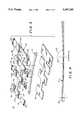
- FIG. 5is a table providing general anthropometric data for use in selecting different size splints based on various leg lengths.
- FIG. 1is a side view of the novel knee immobilizer splint 10 in place on a leg 8.
- the splint 10includes a rigid spine 11 that may be formed of stiff plastic or metal.
- the spine 11is preferably of stiff aluminum that is about 0.375 inches in thickness, 1.5 inches in width and about 26.5 inches long for a medium size leg.
- a smaller size splintcould be used for a small leg, where the spine 11 is about 23 inches long, or about 29.4 inches long for a longer leg (See FIG. 5).
- FIG. 5See FIG. 5
- the spine 11is bent upwardly about 5°, with the included angle 32 of 175° intended in use to face the posterior of the knee so as to increase the clearance between the back of the knee and the splint and also to provide maximal extension to the knee.
- a gap 31exists between the back or posterior 33 of the knee 35 and the spine 11.
- a frame 12, shown more clearly in the exploded view in FIG. 3,preferably is formed of flexible plastic such as 0.060 inches thick polyethylene that is shaped as shown in FIG. 3 to cover the spine 11, and also to tether the straps 14, 15, 16 and 17, which are inserted through appropriately matching slots.
- the frame 12can be attached to spine 11 with rivets 39, as illustrated in FIG. 3 or with appropriate adhesive.
- a liner 13 shaped as shown in FIG. 4 and made from a cushioning material such as 0.375 inch thick of a foam material such as Velfoam, manufactured by the Velcro Companyis applied below the spine 11.
- the liner 13may be provided with a high friction material 13A such as Volextra, provided by Voltec Inc. of Lawrence, Mass., at suitable locations on the liner 13.
- the liner 13may be attached to the frame 12 with adhesive, and sandwiches the spine 11 there between.
- the high friction material 13Aalso may be adhesively applied, and is preferably about 1/16" thick.
- the straps 14, 15, 16 and 17are of conventional hook and loop construction with D-rings 28 (or 30) at one end and a loop material at the other end, such that when the strap 16 is inserted into a D-ring 28, it may be wrapped back on itself so that the hook and loop material 31 engage in known fashion. It is preferable, as shown, to have every other strap 14 and 16, and 15 and 17, assembled with the D-ring in the opposite direction so that the tightening forces are neutral.
- the strapsalso will include a portion of the high friction material to minimize movement along the leg.
- the splint 10is attached to a leg 8 with the liner 13 in cushioning contact with the upper leg or thigh, under the area of strap 14, and in contact with the lower leg or calf under strap 16. Because of the 5° inward bend in the spine 11, there is automatically provided some clearance between the posterior 33 of the knee 35, in the area between the straps 15 and 16. Therefore, with tensioning of straps 15 and 16, pressure is applied to the anterior aspect of the limb 8 above and below the knee joint 35 and the knee 35 is therefore pressed into extension as desired, to a maximal extension. As can be seen from FIG. 1, even without the 5° bend in the spine 11, there would be some clearance behind the knee; however, the bend assures enough clearance to accommodate a wide range in size of patients, and provides other advantages as hereinafter described.
- FIG. 3is an exploded view of the elements of the splint 10. It comprises the stiff spine 11. It also includes the frame 12, having the straps 14, 15, 16 and 17 for tightening about the leg as illustrated in FIG. 1. Strap 14 is located in the area of the thigh and is therefore the widest strap with the greatest transverse length on the frame 12. The spaced transverse portions for straps 15, 16 and 17 are somewhat narrower because they are located in areas where less pressure is required, but they still are generally wider than prior devices, to assure contact and to minimize splint movement.
- the strap 14may be three inches in width and have a 30 inch length, while straps 15, 16 and 17 each may have a 2 inch width with strap 15 having a length of 20.5 inches, strap 16 having a length of 25.5 inches and strap 17 having a length of 18 inches. Of course these are examples only and could be varied as needed for a particular sized leg.
- the straps 14, 15, 16 and 17thread under loops 22 and 23 defined by slots 14A, 15A, 16A and 17A provided in the polyethylene frame 12. Rivets 39 may be used to attach each of the transverse areas of the frame 12 to the spine 11.
- Appropriate sized D-rings 28 and 30may be used with the straps 14, 15, 16 and 17 such that each strap can be threaded through the "D" ring and pulled backwards over itself so that the hook and loop material will attach the strap to itself and hold it in the desired fixed position.
- the liner 13is shaped as shown in FIG. 2 to cover the spine 11 and the tethered straps 14, 15, 16 and 17.
- the liner 13is formed from a cushioning material such as 0.375 inches thick of foam material.
- FIG. 2is a side view of the splint 10 attached to the leg 8 with a CryocuffTM dressing 18 of the type disclosed in said application Ser. No. 644,835, normally retained by the pair of straps 15 and 16 to maintain the dressing 18 in place without any compression at the back of the knee.
- This of coursepermits significant compression around the suprapatella area where it is needed without any pressure at the back of the knee 33 where the pressure is unneeded and in fact, may be harmful.
- FIG. 4is a side view of the novel spine 11 illustrating the 5° bend slightly off center and providing an included angle 32 of 175°. If desired, one or both ends of the spine 11 may be bent backwards in the opposite direction, as illustrated at 34, to avoid sharp contact with the thigh and ankle.
- a novel splintthat provides for immobilization of the knee in varying degrees of extension and in maximal extension.
- the splintdoes not have any hinges.
- the knee immobilizationis mostly open around the knee for comfort, and also permits convenient application of supplemental cold and compression dressings thereto.
- the spineis stiff aluminum about 0.375 inches in thickness, 1.5 inch in width and about 26.5 inches long for a medium sized leg. At about 45% from the thigh end, the spine is bent about 5° so as to increase the clearance between the back of the knee and the splint. The two ends of the spine may also be bent slightly in the opposite direction to avoid sharp contact with the thigh and ankle.
Landscapes
- Health & Medical Sciences (AREA)
- Nursing (AREA)
- Orthopedic Medicine & Surgery (AREA)
- Engineering & Computer Science (AREA)
- Biomedical Technology (AREA)
- Heart & Thoracic Surgery (AREA)
- Vascular Medicine (AREA)
- Life Sciences & Earth Sciences (AREA)
- Animal Behavior & Ethology (AREA)
- General Health & Medical Sciences (AREA)
- Public Health (AREA)
- Veterinary Medicine (AREA)
- Orthopedics, Nursing, And Contraception (AREA)
Abstract
Description
Claims (12)
Priority Applications (1)
| Application Number | Priority Date | Filing Date | Title |
|---|---|---|---|
| US08/148,937US5387185A (en) | 1993-11-08 | 1993-11-08 | Knee immobilizer splint |
Applications Claiming Priority (1)
| Application Number | Priority Date | Filing Date | Title |
|---|---|---|---|
| US08/148,937US5387185A (en) | 1993-11-08 | 1993-11-08 | Knee immobilizer splint |
Publications (1)
| Publication Number | Publication Date |
|---|---|
| US5387185Atrue US5387185A (en) | 1995-02-07 |
Family
ID=22528107
Family Applications (1)
| Application Number | Title | Priority Date | Filing Date |
|---|---|---|---|
| US08/148,937Expired - LifetimeUS5387185A (en) | 1993-11-08 | 1993-11-08 | Knee immobilizer splint |
Country Status (1)
| Country | Link |
|---|---|
| US (1) | US5387185A (en) |
Cited By (29)
| Publication number | Priority date | Publication date | Assignee | Title |
|---|---|---|---|---|
| US5651375A (en)* | 1996-10-23 | 1997-07-29 | Bio-Guardian Systems, Inc. | Prisoner immobilization device |
| WO1998034571A1 (en)* | 1997-02-08 | 1998-08-13 | Medi Bayreuth Weihermüller Und Voigtmann Gmbh & Co. Kg | Orthopedic splint |
| US5829443A (en)* | 1996-10-23 | 1998-11-03 | Cunningham; James | Immobilization device and method |
| DE19817628A1 (en)* | 1998-04-21 | 1999-11-11 | Schuett & Grundei Orthopaedie | Modular knee support orthosis for fast treatment of patients |
| US6524265B2 (en) | 2001-04-27 | 2003-02-25 | Theodore B. Hogg | Leg brace support structure |
| US6623439B2 (en) | 2001-08-31 | 2003-09-23 | Dj Orthopedics, Llc | Contoured knee brace frame |
| US6764457B2 (en) | 2001-04-27 | 2004-07-20 | Hogg Theodore B | Leg brace support structure |
| FR2857855A1 (en)* | 2003-07-25 | 2005-01-28 | Jean Paul Parizot | Knee orthosis for preventing hyperextension of knee of patient, has central vertical framework comprising sheath to receive splint and positioning straps extending transversely on both sides of framework |
| US20050288615A1 (en)* | 2004-06-25 | 2005-12-29 | Gaylord Eric L | Ankle stabilizing apparatus with sheet members having high coefficient of friction |
| WO2006120498A3 (en)* | 2005-05-09 | 2007-03-22 | Bsn Medical Gmbh And Co Kg | Knee immobilizer |
| US20070083136A1 (en)* | 2005-10-12 | 2007-04-12 | Ossur Hf | Knee brace |
| US7513881B1 (en)* | 2005-01-12 | 2009-04-07 | Ossur Hf | Knee immobilizer |
| US20090277229A1 (en)* | 2008-05-12 | 2009-11-12 | Smith James C | System and Method for Restraining a Person |
| US20100063433A1 (en)* | 2008-09-05 | 2010-03-11 | Linares Medical Devices, Llc | Temporary splint assembly with semi-rigid wrap around supports in combination with intermediately positioned joint cast |
| US20140208490A1 (en)* | 2013-01-28 | 2014-07-31 | Oscar Freixas | Self-adjusting system for joint protection |
| US8870802B1 (en) | 2011-04-13 | 2014-10-28 | Water Crest Industries LLC | Traction splint |
| USD737327S1 (en) | 2013-06-17 | 2015-08-25 | Covidien Lp | Display screen with a transitional leak detection icon |
| USD737328S1 (en) | 2013-06-17 | 2015-08-25 | Covidien Lp | Display screen with graphical user interface for venous refill detection |
| USD737855S1 (en) | 2013-06-17 | 2015-09-01 | Covidien Lp | Display screen with a transitional venous refill detection icon |
| US20150335456A1 (en)* | 2014-05-23 | 2015-11-26 | Dana Salsbery | Adjustable leg brace systems and methods |
| USD760728S1 (en) | 2013-06-17 | 2016-07-05 | Covidien Lp | Display screen with graphical user interface for patient use meter reset |
| USD774057S1 (en) | 2013-06-17 | 2016-12-13 | Covidien Lp | Display screen with a graphical user interface for compliance monitoring |
| KR101882877B1 (en)* | 2018-03-09 | 2018-07-30 | 김웅범 | Assistance apparatus for walk |
| US10258831B1 (en)* | 2012-09-14 | 2019-04-16 | Catherine Grander Vance | Swim training devices |
| US11019858B1 (en) | 2013-01-28 | 2021-06-01 | Oscar Freixas | Self-adjusting system for joint protection |
| US20220001178A1 (en)* | 2020-07-03 | 2022-01-06 | Hoi Ming Michael HO | Body joint support device with inflatable airbag, electrode or both |
| WO2022046858A1 (en)* | 2020-08-31 | 2022-03-03 | Singh Brig Mohan | Posterior knee guard |
| US20230069860A1 (en)* | 2021-09-09 | 2023-03-09 | Stephen Eugene Juaire | Apparatus, system, and method for at least one of icing, heating, and compressing a user's body part |
| US20230233379A1 (en)* | 2021-09-09 | 2023-07-27 | Stephen Eugene Juaire | Apparatus, system, and method for at least one of icing, heating, and compressing a user's body part |
Citations (8)
| Publication number | Priority date | Publication date | Assignee | Title |
|---|---|---|---|---|
| US3526222A (en)* | 1968-05-24 | 1970-09-01 | Robert E Dreibelbis | Pediatric restraining apparatus |
| US3831467A (en)* | 1973-03-16 | 1974-08-27 | R Moore | Knee brace |
| US3933154A (en)* | 1974-01-15 | 1976-01-20 | Cabansag Edwin M | Immobilizer device |
| US4090508A (en)* | 1977-03-15 | 1978-05-23 | Medical Specialties, Incorporated | Orthopedic knee brace |
| US4111194A (en)* | 1976-12-27 | 1978-09-05 | Rollin Webb Cox | Posterior knee immobilizing brace |
| US4848326A (en)* | 1988-06-20 | 1989-07-18 | Robert Lonardo | Knee contracture correction device |
| US5230335A (en)* | 1991-01-23 | 1993-07-27 | Aircast, Inc. | Thermal compress system |
| US5267949A (en)* | 1992-03-25 | 1993-12-07 | Manuel De La Torre | Positioning device for a lower extremity |
- 1993
- 1993-11-08USUS08/148,937patent/US5387185A/ennot_activeExpired - Lifetime
Patent Citations (8)
| Publication number | Priority date | Publication date | Assignee | Title |
|---|---|---|---|---|
| US3526222A (en)* | 1968-05-24 | 1970-09-01 | Robert E Dreibelbis | Pediatric restraining apparatus |
| US3831467A (en)* | 1973-03-16 | 1974-08-27 | R Moore | Knee brace |
| US3933154A (en)* | 1974-01-15 | 1976-01-20 | Cabansag Edwin M | Immobilizer device |
| US4111194A (en)* | 1976-12-27 | 1978-09-05 | Rollin Webb Cox | Posterior knee immobilizing brace |
| US4090508A (en)* | 1977-03-15 | 1978-05-23 | Medical Specialties, Incorporated | Orthopedic knee brace |
| US4848326A (en)* | 1988-06-20 | 1989-07-18 | Robert Lonardo | Knee contracture correction device |
| US5230335A (en)* | 1991-01-23 | 1993-07-27 | Aircast, Inc. | Thermal compress system |
| US5267949A (en)* | 1992-03-25 | 1993-12-07 | Manuel De La Torre | Positioning device for a lower extremity |
Non-Patent Citations (8)
| Title |
|---|
| Irrgang, J. J., "Postoperative Rehabilitation Following Anterior Cruciate Ligament Reconstruction," Clinics in Sports Medicine, vol. 12, No. 4, Oct. 1993, pp. 807-813. |
| Irrgang, J. J., Postoperative Rehabilitation Following Anterior Cruciate Ligament Reconstruction, Clinics in Sports Medicine, vol. 12, No. 4, Oct. 1993, pp. 807 813.* |
| Knee Immobilizers, Zimmer, 1989, product brochure.* |
| Tecnol, Inc., Orthopedic Soft Goods, pp. 22 23, product brochure, undated.* |
| Tecnol, Inc., Orthopedic Soft Goods, pp. 22-23, product brochure, undated. |
| Watco Orthopedics, The Wonderbrace Series, 1992, product brochure.* |
| Watco Products, Inc., "Design and Manufacture of Orthopaedic Specialities," pp. 1-10, product brochure, undated. |
| Watco Products, Inc., Design and Manufacture of Orthopaedic Specialities, pp. 1 10, product brochure, undated.* |
Cited By (43)
| Publication number | Priority date | Publication date | Assignee | Title |
|---|---|---|---|---|
| US5651375A (en)* | 1996-10-23 | 1997-07-29 | Bio-Guardian Systems, Inc. | Prisoner immobilization device |
| US5829443A (en)* | 1996-10-23 | 1998-11-03 | Cunningham; James | Immobilization device and method |
| WO1998034571A1 (en)* | 1997-02-08 | 1998-08-13 | Medi Bayreuth Weihermüller Und Voigtmann Gmbh & Co. Kg | Orthopedic splint |
| DE19817628A1 (en)* | 1998-04-21 | 1999-11-11 | Schuett & Grundei Orthopaedie | Modular knee support orthosis for fast treatment of patients |
| US6764457B2 (en) | 2001-04-27 | 2004-07-20 | Hogg Theodore B | Leg brace support structure |
| US6524265B2 (en) | 2001-04-27 | 2003-02-25 | Theodore B. Hogg | Leg brace support structure |
| US6623439B2 (en) | 2001-08-31 | 2003-09-23 | Dj Orthopedics, Llc | Contoured knee brace frame |
| US6878126B2 (en) | 2001-08-31 | 2005-04-12 | Dj Orthopedics, Llc | Contoured knee brace frame |
| FR2857855A1 (en)* | 2003-07-25 | 2005-01-28 | Jean Paul Parizot | Knee orthosis for preventing hyperextension of knee of patient, has central vertical framework comprising sheath to receive splint and positioning straps extending transversely on both sides of framework |
| WO2005018487A3 (en)* | 2003-07-25 | 2005-05-06 | Jean-Paul Parizot | Knee orthosis |
| US20050288615A1 (en)* | 2004-06-25 | 2005-12-29 | Gaylord Eric L | Ankle stabilizing apparatus with sheet members having high coefficient of friction |
| US7513881B1 (en)* | 2005-01-12 | 2009-04-07 | Ossur Hf | Knee immobilizer |
| US7892195B2 (en) | 2005-01-12 | 2011-02-22 | Ossur Hf | Knee immobilizer |
| US20090182253A1 (en)* | 2005-01-12 | 2009-07-16 | Ossur Hf | Knee immobilizer |
| US7837642B2 (en) | 2005-05-09 | 2010-11-23 | Bsn Medical Gmbh | Knee immobilizer |
| US20090216166A1 (en)* | 2005-05-09 | 2009-08-27 | Bsn Medical, Inc. | Knee immobilizer |
| JP2008539926A (en)* | 2005-05-09 | 2008-11-20 | ビーエスエヌ メディカル ゲーエムベーハー アンド シーオー.ケージー | Knee fixator |
| WO2006120498A3 (en)* | 2005-05-09 | 2007-03-22 | Bsn Medical Gmbh And Co Kg | Knee immobilizer |
| US8216166B2 (en) | 2005-10-12 | 2012-07-10 | Ossur Hf | Knee brace |
| US7704218B2 (en) | 2005-10-12 | 2010-04-27 | Ossur, Hf | Knee brace |
| US20070083136A1 (en)* | 2005-10-12 | 2007-04-12 | Ossur Hf | Knee brace |
| US20090277229A1 (en)* | 2008-05-12 | 2009-11-12 | Smith James C | System and Method for Restraining a Person |
| US8257290B2 (en) | 2008-09-05 | 2012-09-04 | Linares Medical Devices, Llc | Temporary splint assembly with semi-rigid wrap around supports in combination with intermediately positioned joint cast |
| US20100063433A1 (en)* | 2008-09-05 | 2010-03-11 | Linares Medical Devices, Llc | Temporary splint assembly with semi-rigid wrap around supports in combination with intermediately positioned joint cast |
| US8870802B1 (en) | 2011-04-13 | 2014-10-28 | Water Crest Industries LLC | Traction splint |
| US10258831B1 (en)* | 2012-09-14 | 2019-04-16 | Catherine Grander Vance | Swim training devices |
| US20140208490A1 (en)* | 2013-01-28 | 2014-07-31 | Oscar Freixas | Self-adjusting system for joint protection |
| US11019858B1 (en) | 2013-01-28 | 2021-06-01 | Oscar Freixas | Self-adjusting system for joint protection |
| USD737327S1 (en) | 2013-06-17 | 2015-08-25 | Covidien Lp | Display screen with a transitional leak detection icon |
| USD737328S1 (en) | 2013-06-17 | 2015-08-25 | Covidien Lp | Display screen with graphical user interface for venous refill detection |
| USD737855S1 (en) | 2013-06-17 | 2015-09-01 | Covidien Lp | Display screen with a transitional venous refill detection icon |
| USD760728S1 (en) | 2013-06-17 | 2016-07-05 | Covidien Lp | Display screen with graphical user interface for patient use meter reset |
| USD774057S1 (en) | 2013-06-17 | 2016-12-13 | Covidien Lp | Display screen with a graphical user interface for compliance monitoring |
| US20150335456A1 (en)* | 2014-05-23 | 2015-11-26 | Dana Salsbery | Adjustable leg brace systems and methods |
| US10092438B2 (en)* | 2014-05-23 | 2018-10-09 | Dana Salsbery | Adjustable leg brace systems and methods |
| KR101882877B1 (en)* | 2018-03-09 | 2018-07-30 | 김웅범 | Assistance apparatus for walk |
| US20220001178A1 (en)* | 2020-07-03 | 2022-01-06 | Hoi Ming Michael HO | Body joint support device with inflatable airbag, electrode or both |
| US11911618B2 (en)* | 2020-07-03 | 2024-02-27 | Hoi Ming Michael HO | Body joint support device with inflatable airbag, electrode or both |
| WO2022046858A1 (en)* | 2020-08-31 | 2022-03-03 | Singh Brig Mohan | Posterior knee guard |
| US20230069860A1 (en)* | 2021-09-09 | 2023-03-09 | Stephen Eugene Juaire | Apparatus, system, and method for at least one of icing, heating, and compressing a user's body part |
| US11638468B2 (en)* | 2021-09-09 | 2023-05-02 | Stephen Eugene Juaire | Apparatus, system, and method for at least one of icing, heating, and compressing a user's body part |
| US20230233379A1 (en)* | 2021-09-09 | 2023-07-27 | Stephen Eugene Juaire | Apparatus, system, and method for at least one of icing, heating, and compressing a user's body part |
| US12193915B2 (en)* | 2021-09-09 | 2025-01-14 | Stephen Eugene Juaire | Apparatus, system, and method for at least one of icing, heating, and compressing a user's body part |
Similar Documents
| Publication | Publication Date | Title |
|---|---|---|
| US5387185A (en) | Knee immobilizer splint | |
| US4407276A (en) | Brace for articulated limbs | |
| US5843010A (en) | Heel and ankle appliance | |
| US5873848A (en) | Orthopedic brace | |
| US4495942A (en) | Dynamic ankle brace | |
| US4587962A (en) | Tibia/ankle orthosis | |
| USRE37297E1 (en) | Dynamic orthopedic knee brace assembly | |
| US6402712B1 (en) | Dual action knee strap | |
| US5700237A (en) | Device for correcting ankle contractures | |
| US5486157A (en) | Dynamic multi-angular ankle and foot orthosis device | |
| US4844094A (en) | Ankle brace | |
| US4494534A (en) | Universal leg brace system | |
| US4794916A (en) | Lumbar stabilizer | |
| US6056713A (en) | Moldable custom-fitted ankle brace | |
| US9320639B2 (en) | Compression wrap | |
| US4646726A (en) | Ankle joint orthosis | |
| US5058576A (en) | Adjustable wrist and hand splint | |
| US5139476A (en) | Orthotic knee wrap | |
| US5902259A (en) | Therapeutic ankle orthosis | |
| US4905678A (en) | Hip stabilizer | |
| US5514082A (en) | Knee brace for maintaining the patella away from an irritated area of the knee | |
| US4862877A (en) | Hand splint for wrist support with optional support of MP joints and thumb and IP finger assists | |
| US3853123A (en) | Orthopedic knee brace | |
| US5393303A (en) | Attachment for leg and foot joint | |
| US4981132A (en) | Orthosis for the treatment of tibial torsion in children |
Legal Events
| Date | Code | Title | Description |
|---|---|---|---|
| AS | Assignment | Owner name:AIRCAST, INCORPORATED, NEW JERSEY Free format text:ASSIGNMENT OF ASSIGNORS INTEREST;ASSIGNORS:JOHNSON, GLENN W. JR.;MCVICKER, HENRY J.;REEL/FRAME:006771/0387 Effective date:19931104 | |
| STCF | Information on status: patent grant | Free format text:PATENTED CASE | |
| FPAY | Fee payment | Year of fee payment:4 | |
| AS | Assignment | Owner name:BANK OF NEW YORK, THE, NEW JERSEY Free format text:SECURITY INTEREST;ASSIGNOR:AIRCAST INCORPORATED;REEL/FRAME:012621/0100 Effective date:20020213 | |
| FPAY | Fee payment | Year of fee payment:8 | |
| SULP | Surcharge for late payment | Year of fee payment:7 | |
| REMI | Maintenance fee reminder mailed | ||
| AS | Assignment | Owner name:MERRILL LYNCH FINANCIAL SERVICES, INC., ILLINOIS Free format text:SECURITY AGREEMENT;ASSIGNOR:AIRCAST INCORPORATED;REEL/FRAME:013599/0074 Effective date:20021217 | |
| AS | Assignment | Owner name:AIRCAST INCORPORATED, NEW JERSEY Free format text:ASSIGNMENT OF ASSIGNORS INTEREST;ASSIGNOR:BANK OF NEW YORK, THE;REEL/FRAME:013669/0437 Effective date:20030110 | |
| AS | Assignment | Owner name:CREDIT SUISSE FIRST BOSTON, AS FIRST LIEN COLLATER Free format text:SECURITY AGREEMENT;ASSIGNOR:AIRCAST LLC;REEL/FRAME:016153/0229 Effective date:20041207 | |
| AS | Assignment | Owner name:CREDIT SUISSE FIRST BOSTON, AS SECOND LIEN COLLATE Free format text:SECURITY INTEREST;ASSIGNOR:AIRCAST LLC;REEL/FRAME:016547/0792 Effective date:20041207 | |
| AS | Assignment | Owner name:AIRCAST, INCORPORATED, NEW JERSEY Free format text:RELEASE OF SECURITY INTEREST;ASSIGNOR:MERRILL LYNCH BUSINESS FINANCIAL SERVICES, INC.;REEL/FRAME:015841/0915 Effective date:20041207 Owner name:AIRCAST LLC, NEW JERSEY Free format text:ASSIGNMENT OF ASSIGNORS INTEREST;ASSIGNOR:AI ASSET ACQUISITION COMPANY LLC;REEL/FRAME:015841/0921 Effective date:20041207 Owner name:AI ASSET ACQUISITION COMPANY LLC, NEW JERSEY Free format text:ASSIGNMENT OF ASSIGNORS INTEREST;ASSIGNOR:AIRCAST INCORPORATED;REEL/FRAME:015870/0621 Effective date:20041207 Owner name:AIRCAST, INCORPORATED,NEW JERSEY Free format text:RELEASE OF SECURITY INTEREST;ASSIGNOR:MERRILL LYNCH BUSINESS FINANCIAL SERVICES, INC.;REEL/FRAME:015841/0915 Effective date:20041207 Owner name:AIRCAST LLC,NEW JERSEY Free format text:ASSIGNMENT OF ASSIGNORS INTEREST;ASSIGNOR:AI ASSET ACQUISITION COMPANY LLC;REEL/FRAME:015841/0921 Effective date:20041207 | |
| AS | Assignment | Owner name:AIRCAST LLC,NEW JERSEY Free format text:RELEASE BY SECURED PARTY;ASSIGNOR:CREDIT SUISSE FIRST BOSTON, AS SECOND LIEN COLLATERAL AGENT;REEL/FRAME:017480/0381 Effective date:20060407 Owner name:AIRCAST LLC, NEW JERSEY Free format text:RELEASE BY SECURED PARTY;ASSIGNOR:CREDIT SUISSE FIRST BOSTON, AS SECOND LIEN COLLATERAL AGENT;REEL/FRAME:017480/0381 Effective date:20060407 | |
| AS | Assignment | Owner name:WACHOVIA BANK, N.A.,NORTH CAROLINA Free format text:SECURITY AGREEMENT;ASSIGNOR:AIRCAST LLC;REEL/FRAME:017619/0445 Effective date:20060406 Owner name:WACHOVIA BANK, N.A., NORTH CAROLINA Free format text:SECURITY AGREEMENT;ASSIGNOR:AIRCAST LLC;REEL/FRAME:017619/0445 Effective date:20060406 | |
| AS | Assignment | Owner name:AIRCAST LLC, NEW JERSEY Free format text:RELEASE BY SECURED PARTY;ASSIGNOR:CREDIT SUISSE FIRST BOSTON AS FIRST LIEN ADMINISTRATIVE AGENT AND FIRST LIEN COLLATERAL AGENT;REEL/FRAME:017681/0773 Effective date:20060407 Owner name:AIRCAST HOLDING COMPANY LLC, NEW JERSEY Free format text:RELEASE BY SECURED PARTY;ASSIGNOR:CREDIT SUISSE FIRST BOSTON AS FIRST LIEN ADMINISTRATIVE AGENT AND FIRST LIEN COLLATERAL AGENT;REEL/FRAME:017681/0773 Effective date:20060407 Owner name:AIRCAST LLC,NEW JERSEY Free format text:RELEASE BY SECURED PARTY;ASSIGNOR:CREDIT SUISSE FIRST BOSTON AS FIRST LIEN ADMINISTRATIVE AGENT AND FIRST LIEN COLLATERAL AGENT;REEL/FRAME:017681/0773 Effective date:20060407 Owner name:AIRCAST HOLDING COMPANY LLC,NEW JERSEY Free format text:RELEASE BY SECURED PARTY;ASSIGNOR:CREDIT SUISSE FIRST BOSTON AS FIRST LIEN ADMINISTRATIVE AGENT AND FIRST LIEN COLLATERAL AGENT;REEL/FRAME:017681/0773 Effective date:20060407 | |
| FPAY | Fee payment | Year of fee payment:12 | |
| AS | Assignment | Owner name:DJO, LLC, CALIFORNIA Free format text:ASSIGNMENT OF ASSIGNORS INTEREST;ASSIGNOR:AIRCAST LLC;REEL/FRAME:019628/0712 Effective date:20070220 Owner name:DJO, LLC,CALIFORNIA Free format text:ASSIGNMENT OF ASSIGNORS INTEREST;ASSIGNOR:AIRCAST LLC;REEL/FRAME:019628/0712 Effective date:20070220 | |
| AS | Assignment | Owner name:DJO, LLC, CALIFORNIA Free format text:RELEASE BY SECURED PARTY;ASSIGNOR:WACHOVIA BANK, NATIONAL ASSOCIATION, AS ADMINISTRATIVE AGENT;REEL/FRAME:020196/0931 Effective date:20071120 Owner name:DJO, LLC,CALIFORNIA Free format text:RELEASE BY SECURED PARTY;ASSIGNOR:WACHOVIA BANK, NATIONAL ASSOCIATION, AS ADMINISTRATIVE AGENT;REEL/FRAME:020196/0931 Effective date:20071120 | |
| AS | Assignment | Owner name:CREDIT SUISSE, AS COLLATERAL AGENT, NEW YORK Free format text:SECURITY AGREEMENT;ASSIGNOR:DJO, LLC;REEL/FRAME:020234/0393 Effective date:20071120 Owner name:DJO, LLC, CALIFORNIA Free format text:CORRECTIVE ASSIGNMENT TO CORRECT THE ASSIGEE'S NAME IN ORIGINAL ASSIGNMENT DOCUMENT PREVIOUSLY RECORDED ON REEL 019628 FRAME 0712;ASSIGNOR:AIRCAST, LLC;REEL/FRAME:020234/0252 Effective date:20070220 Owner name:DJO, LLC,CALIFORNIA Free format text:CORRECTIVE ASSIGNMENT TO CORRECT THE ASSIGEE'S NAME IN ORIGINAL ASSIGNMENT DOCUMENT PREVIOUSLY RECORDED ON REEL 019628 FRAME 0712. ASSIGNOR(S) HEREBY CONFIRMS THE THE ASSIGNEE'S NAME IS DJO, LLC.;ASSIGNOR:AIRCAST, LLC;REEL/FRAME:020234/0252 Effective date:20070220 Owner name:DJO, LLC, CALIFORNIA Free format text:CORRECTIVE ASSIGNMENT TO CORRECT THE ASSIGEE'S NAME IN ORIGINAL ASSIGNMENT DOCUMENT PREVIOUSLY RECORDED ON REEL 019628 FRAME 0712. ASSIGNOR(S) HEREBY CONFIRMS THE THE ASSIGNEE'S NAME IS DJO, LLC.;ASSIGNOR:AIRCAST, LLC;REEL/FRAME:020234/0252 Effective date:20070220 Owner name:CREDIT SUISSE, AS COLLATERAL AGENT,NEW YORK Free format text:SECURITY AGREEMENT;ASSIGNOR:DJO, LLC;REEL/FRAME:020234/0393 Effective date:20071120 | |
| AS | Assignment | Owner name:ENCORE MEDICAL ASSET CORPORATION, CALIFORNIA Free format text:RELEASE BY SECURED PARTY;ASSIGNOR:CREDIT SUISSE AG, AS COLLATERAL AGENT;REEL/FRAME:035706/0497 Effective date:20150507 Owner name:RIKCO INTERNATIONAL, LLC, WISCONSIN Free format text:RELEASE BY SECURED PARTY;ASSIGNOR:CREDIT SUISSE AG, AS COLLATERAL AGENT;REEL/FRAME:035706/0497 Effective date:20150507 Owner name:DJO, LLC, CALIFORNIA Free format text:RELEASE BY SECURED PARTY;ASSIGNOR:CREDIT SUISSE AG, AS COLLATERAL AGENT;REEL/FRAME:035706/0497 Effective date:20150507 |