US5386925A - Expansion tank - Google Patents
Expansion tankDownload PDFInfo
- Publication number
- US5386925A US5386925AUS08/078,837US7883793AUS5386925AUS 5386925 AUS5386925 AUS 5386925AUS 7883793 AUS7883793 AUS 7883793AUS 5386925 AUS5386925 AUS 5386925A
- Authority
- US
- United States
- Prior art keywords
- diaphragm
- peripheral portion
- tank
- side wall
- peripheral
- Prior art date
- Legal status (The legal status is an assumption and is not a legal conclusion. Google has not performed a legal analysis and makes no representation as to the accuracy of the status listed.)
- Expired - Lifetime
Links
Images


Classifications
- F—MECHANICAL ENGINEERING; LIGHTING; HEATING; WEAPONS; BLASTING
- F24—HEATING; RANGES; VENTILATING
- F24D—DOMESTIC- OR SPACE-HEATING SYSTEMS, e.g. CENTRAL HEATING SYSTEMS; DOMESTIC HOT-WATER SUPPLY SYSTEMS; ELEMENTS OR COMPONENTS THEREFOR
- F24D3/00—Hot-water central heating systems
- F24D3/10—Feed-line arrangements, e.g. providing for heat-accumulator tanks, expansion tanks ; Hydraulic components of a central heating system
- F24D3/1008—Feed-line arrangements, e.g. providing for heat-accumulator tanks, expansion tanks ; Hydraulic components of a central heating system expansion tanks
- F24D3/1016—Tanks having a bladder
- F—MECHANICAL ENGINEERING; LIGHTING; HEATING; WEAPONS; BLASTING
- F16—ENGINEERING ELEMENTS AND UNITS; GENERAL MEASURES FOR PRODUCING AND MAINTAINING EFFECTIVE FUNCTIONING OF MACHINES OR INSTALLATIONS; THERMAL INSULATION IN GENERAL
- F16L—PIPES; JOINTS OR FITTINGS FOR PIPES; SUPPORTS FOR PIPES, CABLES OR PROTECTIVE TUBING; MEANS FOR THERMAL INSULATION IN GENERAL
- F16L55/00—Devices or appurtenances for use in, or in connection with, pipes or pipe systems
- F16L55/04—Devices damping pulsations or vibrations in fluids
- F16L55/045—Devices damping pulsations or vibrations in fluids specially adapted to prevent or minimise the effects of water hammer
- F16L55/05—Buffers therefor
- F16L55/052—Pneumatic reservoirs
- F16L55/053—Pneumatic reservoirs the gas in the reservoir being separated from the fluid in the pipe
- F—MECHANICAL ENGINEERING; LIGHTING; HEATING; WEAPONS; BLASTING
- F24—HEATING; RANGES; VENTILATING
- F24D—DOMESTIC- OR SPACE-HEATING SYSTEMS, e.g. CENTRAL HEATING SYSTEMS; DOMESTIC HOT-WATER SUPPLY SYSTEMS; ELEMENTS OR COMPONENTS THEREFOR
- F24D3/00—Hot-water central heating systems
- F24D3/10—Feed-line arrangements, e.g. providing for heat-accumulator tanks, expansion tanks ; Hydraulic components of a central heating system
- F24D3/1008—Feed-line arrangements, e.g. providing for heat-accumulator tanks, expansion tanks ; Hydraulic components of a central heating system expansion tanks
Definitions
- the inventionrelates to closed hot water heating systems or pressurized water systems, and more particularly to an expansion tank, forming part of the system, and the construction thereof. Stated otherwise, the invention relates to expansion tanks and, more particularly, to improved expansion tanks adapted to form part of a hot water heating system or a pressurized water system.
- Watercontains air in the absorbed state in nearly inverse proportion to its temperature. This air is liberated into the system when the water is heated and accumulates in the compression tank and other portions of the heating system. A reduction in heating efficiency results, making continuous venting of radiators or convectors necessary.
- the water as it is heatedexpands and moves into the compression tank which is connected to the piping through which the water is circulated. When the temperature of the boiler water reaches the desired degree, the firing of the boiler ceases. The water begins to cool and contract. As it cools, that part of the boiler water in direct contact with air in the compression tank absorbs some of the air in the tank. Through thermal circulation this aircharged water in the compression tank is changed continually so that in the next heating cycle this re-absorbed air is liberated into the system. This reversible process is repeated as often as the firing cycle is repeated and the boiler water is heated and cooled. As a result of this process the pressure in the system varies considerably and eventually the system may cease to function.
- Expansion tanks in domestic water systemsprovide an air cushion for the supply water.
- the air and water in early systemswere in direct contact. Air being soluble in water, the water absorbs air. The water in the system might eventually absorb the air cushion in the expansion tanks, leaving a static water system which necessitates the constant operation of a pressure pump. Subsequently an air surge chamber was provided which was not in direct contact with the water, thereby eliminating the need of the pressure pump operating every time a faucet was turned on.
- U.S. Pat. No. 3,035,614discloses expansion tanks which include a pair of hollow body members, each of which have an end and a tubular skirt portion. The skirt portions are united in end-to-end relation to form a tank. There is a flexible diaphragm in and spanning the tank and having a peripheral portion in peripheral engagement with the skirt of one of the body members. A continuous retaining ring engages the peripheral portion and retains it in engagement with the skirt of the body member. There is a groove in the exterior of the ring and a substantially complemental corrugation in the skirt of the body member compressing the peripheral portion into the groove to secure the diaphragm against movement endwise of the tank and seal the diaphragm to the skirt. See also U.S. Pat. No. 2,695,753.
- U.S. Pat. No. 3,524,475discloses expansion tanks which include a hollow body having a side wall and end walls and a liquid-impervious liner having an end wall and a side wall covering the corresponding end wall and a portion of the side wall of the body in adjacent non-adhering relation thereto.
- the linerhas a peripheral edge portion contacting the side wall.
- There is a flexible diaphragmdividing the interior of the body into two sections. One of the sections is adapted to receive a liquid.
- the diaphragmhas a peripheral portion disposed in overlying relation to the peripheral edge portion of the liner.
- the retaining meansincludes a continuous ring engaging and receiving the peripheral portion of the diaphragm.
- the side wallengages the peripheral edge portion of the liner.
- the ring and wallhave a complemental rib and groove securing the diaphragm to the side wall.
- the diaphragmis formed with a bead on its peripheral portion, with the bead being received between the rib and the groove.
- An object of the inventionis to provide an improved storage device in the form of an expansion tank, for use in hot water heating systems, or pressurized water systems, which has a diaphragm which divides the tank into two sections.
- the inventioninvolves an improved storage device in the form of an expansion tank, for use in hot water heating systems, or pressurized water systems, which expansion tank has a diaphragm which divides the tank into two sections. One section is precharged with gas under pressure. The other section is connected to the hot water heating system.
- the inventioninvolves expansion tanks which include a pair of hollow body members.
- Each hollow body memberhas an end wall and a tubular side wall having an end portion.
- the end portions of the side wallsare in end to end relation.
- There is a continuous retaining ringhaving a first peripheral portion and a second peripheral portion.
- the end portions of the side wallsare united to the first peripheral portion so as to form a tank.
- the second peripheral portionis located interior to the first peripheral portion.
- the second peripheral portion of the retaining ringengages and holds the peripheral portion of the diaphragm in peripheral engagement with the side wall.
- the retaining ringis composed of a weldable grade of steel.
- the first peripheral portion of the retaining ringhas an outward extending peripheral protrusion which aligns with the end portions of the side walls of the hollow body members.
- the outward extending peripheral protrusionis a continuous outward extending peripheral rib.
- the end region of the diaphragmhas a continuous outward facing bead
- the end portion of the side wall of one of the hollow body membershas a continuous inward facing groove which corresponds with the outward facing bead of the diaphragm
- the second peripheral portion of the retaining ringhas a continuous outward facing groove which corresponds and mates with the outward facing bead of the diaphragm, thereby securing the diaphragm and liner to the side wall in a liquid-tight sealing manner.
- a liquid-impervious linerhaving an end wall and a side wall disposed in adjacent non-adhering relation to the end wall and the portion of the side wall of the tank enclosing the liquid-receiving section for covering the interior surfaces of the portion of the tank enclosing the liquid-receiving section, is located between the diaphragm and the lower hollow body member, thereby the diaphragm and the liner prevents the liquid from contacting the tank walls.
- the retaining ringis located in assembly position without the need for gauges.
- the retaining ringpreferably has an outward groove on its cylindrical section that controls the position of the diaphragm bead assembly location--such case, the retaining ring cannot move out of position during the forming of the groove in the outer cylindrical surface of the dome of during the operation of the expansion tank.
- the retaining ringpositions the two dome halves without the need for one of the domes to be stepped inwardly (lipped).
- the retaining ringpreferably has an outward bead to separate the two domes sufficiently to provide for welding.
- the retaining ringbecomes a strength reinforcement and an integral part of the tank after it is welded.
- the retaining ringpreferably is made of a weldable grade of steel.
- the present inventionis an improvement of the expansion tank disclosed in U.S. Pat. No. 3,524,475 (Kirk, Jr.) wherein the retaining ring that continuously engages the diaphragm and liner to perform a secure seal has been modified as described herein.
- the inventionalso involves a continuous retaining ring having a first peripheral portion and a second peripheral portion.
- the second peripheral portionis located internal of the first peripheral portion by means of a slanted intermediate portion.
- the first peripheral portionhas an outward extending peripheral protrusion.
- the second peripheral portionhas a inward facing peripheral groove.
- the inventionfurther involves the method of assemblying the invention expansion tank.
- FIG. 1is a vertical cross-sectional view of an expansion tank of the invention
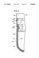
- FIG. 2is an enlarged vertical partial cross-sectional view of the expansion tank, including the retaining ring, of FIG. 1;
- FIG. 3is a schematic diagram of a combination of a hot water heating system and the expansion tank of FIG. 1;
- FIG. 4is a schematic diagram of a combination of a pressurized water system.
- the invention expansion tankis provided with a deformable diaphragm to divide the tank into two sections. One section is precharged with gas under pressure so that the diaphragm is displaced to increase or decrease the volume of this section according to the variations of the volume of water in the other section.
- the variation in volumeis caused when the boiler water is heated and cooled in the normal cyclic operation of the heating system. If the expansion tank is a part of a water system, the variation in volume occurs as tap water is drawn and when the pump operates to replace the water drawn from the tank.
- the diaphragmseparates the gas in the one section of the tank from the water in the system.
- the expansion tank of the diaphragm typein which the inner surface of the portion of the tank defining the water-receiving section is covered with a water impervious liner.
- the lineritself is best fabricated in a separate operation before being installed in the tank. This permits the manufacture of a liner of the desired quality and thickness at a considerable saving as compared with a liner formed on the interior tank surface by a coating process. It would be difficult and expensive both to apply a liner coating as well as to determine whether the deposited liner is of the desired thickness and integrity.
- the wateris thus contained between the liner and the diaphragm so that the entire interior of the expansion tank is shielded from the water.
- corrosion of the tankis prevented regardless of the type of water with which the tank is used or of the temperature experienced within the practical limits of operation of hot water heating systems.
- Thispermits the tank to be constructed of any desired material, without regard to the effect of water on that material.
- expansion tank 100includes upper cylindrical body 102 and lower cylindrical body 104.
- Upper cylindrical body 102has side wall 106 and end wall 108 which is provided with orifice 110.
- End 112 of side wall 106preferably is not an offset edge as in U.S. Pat. No. 3,524,475.
- Lower cylindrical body 104has side wall 114 and end wall 116 which is provided with orifice 118.
- End 120 of side wall 114preferably is not an offset edge.
- a liquid-impervious liner 122which is composed preferably of a plastic capable of withstanding temperatures of at least 212° F., such as, polypropylene, so that the water of a hot water heating system or a pressurized well water system is separated from the interior surfaces of the portion of tank 102 defining bottom section 104 thereof, this being the section that contains the water. Also, plastic liner 122 will not deteriorate due to the temperature or type of water with which tank 100 is used. Liner 122 itself can be manufactured by any suitable technique known to the art; such as, vacuum forming, injection molding, etc.
- the plastic liner 122is formed with an orifice 128 which mates with orifice 118 in end wall 116 of lower cylindrical body 104.
- the portion of liner 122 adjacent the orificeis clamped to lower end wall 116, welded, brazed or otherwise suitably connected to tank 100 at 132 and adapted to connect expansion tank 100 with the water system of which it forms a part.
- Insert 170 which mates with orifice 118 of fitting 130is formed with upwardly extending lip 134, which is adapted to be rolled over to clamp O-ring seal 136, which is preferably of an elastomeric material such as rubber. Insert 170 is attached to fitting 130 and end wall 116 by brazing.
- O-ring 136is compressed between the lip 134 and liner 122, and provides a liquid-tight seal therebetween, thus preventing water in expansion tank 100 from escaping through orifice 128 of plastic liner 122 exteriorly of fitting 130.
- O-ring 136 and bonded joint 132provide a double seal between tank 100 and fitting 130. Bonded joint 132 also seals insert 170 to fitting 130 precluding leakage by the orifice 118/insert 170 interface.
- Retaining (or clamp) ring 138has upper portion 140 and lower portion 142. (See FIG. 2.) Upper portion 140 of retaining ring has bead (or internally facing groove) 144. End 112 of side wall 106 fits tightly over the region of upper portion 140 above bead 144. End 120 of side wall 114 fits tightly over the lower portion 142 below bead 144. Ends 112 and 120 are welded to retaining ring 138 at the interface regions 146 and 148.
- Flexible diaphragm 150formed of butyl rubber or other elastomer, is disposed inside of lower cylindrical body 104 and is adapted to conform to the shape thereof.
- Diaphragm 150has an inward protruding bead (or groove) 152 on the interior surface thereof adjacent its free edge 154.
- Diaphragm 150is so situated that its free edge 154 is adjacent the upper free edge 156 of the liner 122.
- Inward protruding bead (groove) 158 in side wall 114corresponds to and mates with bead 152 of diaphragm 150.
- Lower portion 142 of retaining ring 138contains inward slanted portion 160 and outward facing concave portion 162.
- Concave portion 162corresponds to and mates with bead 152 of diaphragm 150. In this manner, the upper ends of line 122 and diaphragm 150 are anchored to lower cylindrical body 104.
- Conventional air check valve 164secured in orifice 110 in the upper cylindrical body 102, permits air under pressure to be introduced into the gas receiving section 166 between the diaphragm 150 and upper cylindrical body 102. After the pressure in section 166 is raised to the desired value, valve 164 is covered with seal 168.
- the expansion tank (100)can be assembled as follows. Fitting 130 and insert 170 is brazed or welded at 132 to lower end wall 116. Plastic liner 122 is then placed on the interior surface of lower cylindrical body 104, orifice 128 being slipped over insert 170. Next, O-ring 136 is stretched over insert 170, which is then rolled over O-ring 136 to compress it and liner 122 adjacent lower cylindrical body 104.
- Diaphragm 150is placed over liner 122 with bead 152 mating with lower dome 104. Upper edge 120 of lower dome 104 is forced into fit with the region of upper portion 140 of retaining ring 138 below bead 144. At the same time, concave portion 162 of lower portion 142 of retaining ring 138 forcefully fits over bead 152 of diaphragm 150.
- the invention designhas an inwardly protruding groove 158 that at assembly compresses the diaphragm bead between bottom dome side wall surface 104 and retaining ring 138. This compression on the diaphragm bead occurs prior to assemblying the upper dome.
- the "C" shape contour of the ringholds the diaphragm bead in place.
- bead 144is mated up to end 120 of side wall 114. This automatically sets the location of diaphragm bead 152 and the mating concave section 162 of ring 138.
- ring 138is inserted into diaphragm 150 until continuous concave groove 162 of ring 138 is seated in bead section 162 of diaphragm 150.
- Diaphragm 150 and ring 122are then inserted into the open end of water dome 104.
- new ring 138has continuous bead 144 formed in upper portion 140.
- Diaphragm, liner retaining ring 138 and lower dome 104are then put on a grooving machine and groove 158 is formed into the dome, squeezing the diaphragm.
- Lower edge 112 of upper domeis then forced into fit with the region of upper portion 140 of retaining ring 138 below bead 144.
- Lower edge 112 and upper edge 120are welded (preferred), brazed or soldered to bead 144 at 146 and 148, respectively.
- the welding areasare sufficiently spaced from diaphragm 152 and liner 122 so as not to damage them by heating during the welding operation.
- Air under pressurecan be introduced through air check valve 164 until the pressure in gas-receiving section 166 reaches 18 pounds per square inch, for example, and seal 168 is pressed over valve 164 to protect it.
- heated waterexits water heater 170 via line (pipe) 172 and continues through line (pipe) 174, 176.
- the waterreturns via line (pipe) 178 to water heater 170.
- Expansion tank 100is located in line 174, 176 by means of nipple 130 and tee 180. Pressurized water can be put into the line 172, 174, 176, 178 via line (pipe) 182 and valve 184 (located in line 174,176).
- Valve or faucet 186is located in line 176, 178.
- Hot watercan be withdrawn via line 188 (and valve 186).
- Valve 186 and line 188can be replaced by a hot water radiator (not shown). Water flow is shown by the arrows in the figure.
- pressurized waterflows through line 190, 192, 194, 196.
- Valve 198is located in line 190, 192 and valve or faucet 200 is located in line 194,196. Water flow is shown by the arrows in the figure.
- Expansion tank 100is located in line 192, 194 by means of nipple 130 and tee 202.
- the present invention's ring 138has a cylindrical section 140 that has, as part of its surface, a continuous bead 144 that mates to the open end of dome 104. Dome 104's open end does not have to be deformed inwardly (commonly referred to as lipping) as required in the above-mentioned patents. Second dome 102 slides onto ring portion 140 until it reaches the bead 144 of ring 138. Domes 102 and 104 are separated by bead 144 of ring 138 and assembled for welding. Bead 144 of ring 138 provides the necessary spacing while the cylindrical surface 140 of ring 138 provides the backing to facilitate the dome positioning and welding.
Landscapes
- Engineering & Computer Science (AREA)
- General Engineering & Computer Science (AREA)
- Mechanical Engineering (AREA)
- Physics & Mathematics (AREA)
- Thermal Sciences (AREA)
- Chemical & Material Sciences (AREA)
- Combustion & Propulsion (AREA)
- Heat-Pump Type And Storage Water Heaters (AREA)
Abstract
Description
Claims (2)
Priority Applications (1)
| Application Number | Priority Date | Filing Date | Title |
|---|---|---|---|
| US08/078,837US5386925A (en) | 1993-06-21 | 1993-06-21 | Expansion tank |
Applications Claiming Priority (1)
| Application Number | Priority Date | Filing Date | Title |
|---|---|---|---|
| US08/078,837US5386925A (en) | 1993-06-21 | 1993-06-21 | Expansion tank |
Publications (1)
| Publication Number | Publication Date |
|---|---|
| US5386925Atrue US5386925A (en) | 1995-02-07 |
Family
ID=22146508
Family Applications (1)
| Application Number | Title | Priority Date | Filing Date |
|---|---|---|---|
| US08/078,837Expired - LifetimeUS5386925A (en) | 1993-06-21 | 1993-06-21 | Expansion tank |
Country Status (1)
| Country | Link |
|---|---|
| US (1) | US5386925A (en) |
Cited By (42)
| Publication number | Priority date | Publication date | Assignee | Title |
|---|---|---|---|---|
| EP0844400A2 (en) | 1996-10-28 | 1998-05-27 | Amtrol Inc. | Expansion tanks |
| US5806705A (en)* | 1997-12-05 | 1998-09-15 | Essef Corporation | Sealing technique for hydropneumatic pressure vessel |
| US6164486A (en)* | 1999-05-03 | 2000-12-26 | Water Heater Innovations, Inc. | Integral telescoping vessel joint and method for using the same |
| US6264054B1 (en)* | 1999-01-11 | 2001-07-24 | Masaharu Miyake | Vacuum airtight container |
| US6361199B1 (en)* | 2000-03-29 | 2002-03-26 | Maxxon Corporation | Cement mixing apparatus and method |
| US6401966B2 (en)* | 2000-05-23 | 2002-06-11 | Fu Chung Tsai | Plastic pressure vessel structure |
| US6418969B1 (en) | 2000-11-08 | 2002-07-16 | Watts Regulator Co. | In-line thermal expansion tank |
| US20040123912A1 (en)* | 2002-07-24 | 2004-07-01 | Hydac Technology Gmbh | Hydroaccumulator |
| US20050034774A1 (en)* | 2002-07-25 | 2005-02-17 | Robert Lombari | In-line flow through diaphragm tank |
| US20050073118A1 (en)* | 2003-10-07 | 2005-04-07 | Midwest Air Technologies, Inc. | Dolly for portable air compressor |
| US20050210653A1 (en)* | 2004-03-27 | 2005-09-29 | Spartanburg Steel Products, Inc. | Method and apparatus for manufacturing a cylindrical container |
| WO2005113346A2 (en) | 2004-05-12 | 2005-12-01 | Amtrol Inc. | Non-metallic expansion tank with internal diaphragm and clamping device for same |
| US20060021987A1 (en)* | 2004-07-29 | 2006-02-02 | Smolik John V | Pressurized flat conformal tank |
| US20060144843A1 (en)* | 2005-01-05 | 2006-07-06 | Amtrol Inc. | Lined pressure vessel and connector therefor |
| WO2006047244A3 (en)* | 2004-10-21 | 2007-05-10 | Flexcon Ind | Plastic fiber wound pressure tank |
| US20070186873A1 (en)* | 2006-02-13 | 2007-08-16 | Nikolay Polkhouskiy | Pressure control isolation and flood preventative tank for a hot water based heating system |
| US7410087B1 (en)* | 2003-06-18 | 2008-08-12 | Owensby Howard S | Welding backup systems for heat-sink or purge purposes |
| CN100430655C (en)* | 2003-07-22 | 2008-11-05 | 弗莱克斯康工业公司 | Expansion tank with double diaphragm |
| US20090054982A1 (en)* | 2007-08-23 | 2009-02-26 | William Wayne Cimino | Elastic metallic replacement ligament |
| US20100084408A1 (en)* | 2008-10-07 | 2010-04-08 | Li-Ming Wang | Pressure tank having plural access openings |
| US20110132904A1 (en)* | 2009-12-07 | 2011-06-09 | Acker Larry K | Thermal expansion/surge reduction water tank |
| WO2012045011A2 (en) | 2010-10-01 | 2012-04-05 | Amtrol Licensing Inc. | Devices and methods for causing turbulent flow in a tank assembly |
| US8403170B1 (en)* | 2012-04-20 | 2013-03-26 | Ming-Yu Lai | Pressure vessel |
| US8739823B2 (en) | 2010-10-01 | 2014-06-03 | Amtrol Licensing Inc. | Device for causing turbulent flow in a tank assembly |
| US20140158573A1 (en)* | 2012-12-12 | 2014-06-12 | Amtrol Licensing Inc. | Air cell indicator |
| TWI450848B (en)* | 2011-03-11 | 2014-09-01 | Pa E Machinery Ind Co Ltd | The improved diaphragm assembly storage pressure barrel |
| ITPD20130106A1 (en)* | 2013-04-22 | 2014-10-23 | Zilmet S P A | FASTENING SYSTEM WITH PLASTIC LINER FOR EXPANSION VESSELS |
| WO2015183933A1 (en)* | 2014-05-30 | 2015-12-03 | Amtrol Licensing Inc. | Moisture detecting air cap indicator for expansion tank failure |
| US9751689B2 (en) | 2013-09-24 | 2017-09-05 | Pentair Residential Filtration, Llc | Pressure vessel system and method |
| EP3217100A1 (en) | 2016-03-09 | 2017-09-13 | AMTROL Licensing Inc. | Pressure vessel with dome supported diaphragm |
| USD812186S1 (en) | 2016-04-28 | 2018-03-06 | Amtrol Licensing Inc. | Portable gas tank shroud |
| US20180135658A1 (en)* | 2015-05-28 | 2018-05-17 | Zilmet Spa | Expansion Tank with Improved Pipe Fitting |
| IT201700004788A1 (en)* | 2017-01-18 | 2018-07-18 | Varem Spa | EXPANSION VESSEL DIAPHRAGM |
| EP3296645A3 (en)* | 2016-09-20 | 2018-07-25 | AMTROL Licensing Inc. | Fiberwound tanks |
| WO2018218110A1 (en) | 2017-05-26 | 2018-11-29 | Amtrol Licensing Inc. | Water tank with antimicrobial internal liner |
| US10514129B2 (en) | 2016-12-02 | 2019-12-24 | Amtrol Licensing Inc. | Hybrid tanks |
| US10988219B1 (en)* | 2017-06-14 | 2021-04-27 | Hadal, Inc. | System and apparatus for integrated pressure compensator |
| US20210341000A1 (en)* | 2018-10-11 | 2021-11-04 | Flexcon Industries, Inc. | Hydro-pneumatic pressure vessel and diaphragm assembly method |
| US11512804B2 (en) | 2021-04-19 | 2022-11-29 | Shih-Hsin Wang | Expansion tank |
| US20240035673A1 (en)* | 2022-07-29 | 2024-02-01 | Dab Pumps S.P.A. | Expansion vessel with membrane, pump comprising the expansion vessel and relative manufacturing method |
| US20240280223A1 (en)* | 2023-02-17 | 2024-08-22 | Worthington Industries, Inc. | Multi-chamber vessel |
| US12203663B1 (en)* | 2020-02-07 | 2025-01-21 | Enpress Llc | Composite diaphragm expansion vessels |
Citations (32)
| Publication number | Priority date | Publication date | Assignee | Title |
|---|---|---|---|---|
| US2695753A (en)* | 1951-06-09 | 1954-11-30 | American Tube Products Inc | Hot-water heating system |
| US3035614A (en)* | 1959-11-04 | 1962-05-22 | Jr Chester H Kirk | Expansion tank |
| US3137317A (en)* | 1963-06-03 | 1964-06-16 | Melville F Peters | Expansion tank |
| US3165229A (en)* | 1962-09-12 | 1965-01-12 | Gen Fittings Company | Expansion tank |
| US3236411A (en)* | 1962-09-07 | 1966-02-22 | Lander | Expansion tank |
| US3425593A (en)* | 1965-05-22 | 1969-02-04 | Bosch Gmbh Robert | Pressure vessel with a resilient separating membrane |
| US3493496A (en)* | 1968-05-13 | 1970-02-03 | Desalination Systems | Purified water supply apparatus and method |
| US3524475A (en)* | 1968-01-10 | 1970-08-18 | American Tube & Controls Inc | Expansion tank |
| US3929163A (en)* | 1973-07-20 | 1975-12-30 | Greer Hydraulics Inc | Pressure vessel with sensing device |
| US3931834A (en)* | 1974-06-26 | 1976-01-13 | The Goodyear Tire & Rubber Company | Expansion tank diaphragm assembly |
| US3948287A (en)* | 1974-04-12 | 1976-04-06 | Nobuyuki Sugimura | Accumulator |
| US3963612A (en)* | 1974-09-16 | 1976-06-15 | Gossett Charles W | System of water purification and product distribution |
| US3963052A (en)* | 1973-02-20 | 1976-06-15 | Mercier Jacques H | Pressure vessel |
| US4181156A (en)* | 1978-12-04 | 1980-01-01 | Greer Hydraulics, Inc. | Pressure accumulator with anti-extrusion gas charging valve assembly |
| US4192350A (en)* | 1977-12-22 | 1980-03-11 | Normand Trust | Pressure vessel |
| JPS5614401A (en)* | 1979-07-12 | 1981-02-12 | Nissan Motor Co Ltd | Alcohol reforming apparatus |
| US4299254A (en)* | 1980-01-21 | 1981-11-10 | Greer Hydraulics, Incorporated | Pressure accumulator having a long life distensible bladder |
| US4474215A (en)* | 1983-05-19 | 1984-10-02 | A.O. Smith Corporation | Pressure vessel with improved diaphragm mounting |
| US4595037A (en)* | 1984-12-14 | 1986-06-17 | Essef Industries, Inc. | Split tank closure and diaphragm assembly |
| JPS6229641A (en)* | 1985-07-31 | 1987-02-07 | 黒川 敬 | Construction of light weight building |
| JPS6268001A (en)* | 1985-09-17 | 1987-03-27 | Fuji Electric Co Ltd | pantograph collector boat |
| US4667841A (en)* | 1984-12-21 | 1987-05-26 | Gitral S.A. | Tank having two half shells |
| JPS63190902A (en)* | 1987-02-02 | 1988-08-08 | Nok Corp | Bladder for accumulator and manufacture thereof |
| US4784181A (en)* | 1985-10-07 | 1988-11-15 | Flamco B.V. | Expansion tank with a bladder-type diaphragm |
| JPH0292101A (en)* | 1988-09-29 | 1990-03-30 | Mitsubishi Electric Corp | receiving antenna device |
| JPH034902A (en)* | 1989-06-01 | 1991-01-10 | Asahi Chem Ind Co Ltd | Method and device for removing dissolved water in halogen organic solvent |
| JPH03140601A (en)* | 1989-10-25 | 1991-06-14 | Nok Corp | Accumulator bladder |
| JPH03181601A (en)* | 1989-12-08 | 1991-08-07 | Nok Corp | Bladder for accumulator |
| US5062455A (en)* | 1989-08-25 | 1991-11-05 | A. O. Smith Corporation | Pressure vessel with diaphragm compression seal |
| JPH0425601A (en)* | 1990-05-21 | 1992-01-29 | Nok Corp | Bladder for accumulator |
| JPH0439401A (en)* | 1990-06-05 | 1992-02-10 | Yokogawa Electric Corp | Electric-current/pressure convert mechanism |
| US5176178A (en)* | 1991-02-20 | 1993-01-05 | Aos Holding Company | Accumulator with randomly uniplanar bladder collapse |
- 1993
- 1993-06-21USUS08/078,837patent/US5386925A/ennot_activeExpired - Lifetime
Patent Citations (32)
| Publication number | Priority date | Publication date | Assignee | Title |
|---|---|---|---|---|
| US2695753A (en)* | 1951-06-09 | 1954-11-30 | American Tube Products Inc | Hot-water heating system |
| US3035614A (en)* | 1959-11-04 | 1962-05-22 | Jr Chester H Kirk | Expansion tank |
| US3236411A (en)* | 1962-09-07 | 1966-02-22 | Lander | Expansion tank |
| US3165229A (en)* | 1962-09-12 | 1965-01-12 | Gen Fittings Company | Expansion tank |
| US3137317A (en)* | 1963-06-03 | 1964-06-16 | Melville F Peters | Expansion tank |
| US3425593A (en)* | 1965-05-22 | 1969-02-04 | Bosch Gmbh Robert | Pressure vessel with a resilient separating membrane |
| US3524475A (en)* | 1968-01-10 | 1970-08-18 | American Tube & Controls Inc | Expansion tank |
| US3493496A (en)* | 1968-05-13 | 1970-02-03 | Desalination Systems | Purified water supply apparatus and method |
| US3963052A (en)* | 1973-02-20 | 1976-06-15 | Mercier Jacques H | Pressure vessel |
| US3929163A (en)* | 1973-07-20 | 1975-12-30 | Greer Hydraulics Inc | Pressure vessel with sensing device |
| US3948287A (en)* | 1974-04-12 | 1976-04-06 | Nobuyuki Sugimura | Accumulator |
| US3931834A (en)* | 1974-06-26 | 1976-01-13 | The Goodyear Tire & Rubber Company | Expansion tank diaphragm assembly |
| US3963612A (en)* | 1974-09-16 | 1976-06-15 | Gossett Charles W | System of water purification and product distribution |
| US4192350A (en)* | 1977-12-22 | 1980-03-11 | Normand Trust | Pressure vessel |
| US4181156A (en)* | 1978-12-04 | 1980-01-01 | Greer Hydraulics, Inc. | Pressure accumulator with anti-extrusion gas charging valve assembly |
| JPS5614401A (en)* | 1979-07-12 | 1981-02-12 | Nissan Motor Co Ltd | Alcohol reforming apparatus |
| US4299254A (en)* | 1980-01-21 | 1981-11-10 | Greer Hydraulics, Incorporated | Pressure accumulator having a long life distensible bladder |
| US4474215A (en)* | 1983-05-19 | 1984-10-02 | A.O. Smith Corporation | Pressure vessel with improved diaphragm mounting |
| US4595037A (en)* | 1984-12-14 | 1986-06-17 | Essef Industries, Inc. | Split tank closure and diaphragm assembly |
| US4667841A (en)* | 1984-12-21 | 1987-05-26 | Gitral S.A. | Tank having two half shells |
| JPS6229641A (en)* | 1985-07-31 | 1987-02-07 | 黒川 敬 | Construction of light weight building |
| JPS6268001A (en)* | 1985-09-17 | 1987-03-27 | Fuji Electric Co Ltd | pantograph collector boat |
| US4784181A (en)* | 1985-10-07 | 1988-11-15 | Flamco B.V. | Expansion tank with a bladder-type diaphragm |
| JPS63190902A (en)* | 1987-02-02 | 1988-08-08 | Nok Corp | Bladder for accumulator and manufacture thereof |
| JPH0292101A (en)* | 1988-09-29 | 1990-03-30 | Mitsubishi Electric Corp | receiving antenna device |
| JPH034902A (en)* | 1989-06-01 | 1991-01-10 | Asahi Chem Ind Co Ltd | Method and device for removing dissolved water in halogen organic solvent |
| US5062455A (en)* | 1989-08-25 | 1991-11-05 | A. O. Smith Corporation | Pressure vessel with diaphragm compression seal |
| JPH03140601A (en)* | 1989-10-25 | 1991-06-14 | Nok Corp | Accumulator bladder |
| JPH03181601A (en)* | 1989-12-08 | 1991-08-07 | Nok Corp | Bladder for accumulator |
| JPH0425601A (en)* | 1990-05-21 | 1992-01-29 | Nok Corp | Bladder for accumulator |
| JPH0439401A (en)* | 1990-06-05 | 1992-02-10 | Yokogawa Electric Corp | Electric-current/pressure convert mechanism |
| US5176178A (en)* | 1991-02-20 | 1993-01-05 | Aos Holding Company | Accumulator with randomly uniplanar bladder collapse |
Cited By (71)
| Publication number | Priority date | Publication date | Assignee | Title |
|---|---|---|---|---|
| US5778679A (en)* | 1996-10-28 | 1998-07-14 | Amtrol Inc. | Method and apparatus for increasing acceptance and adjusting the rate of pressure variations within a prespecified range in precharged fluid storage systems |
| EP0844400A2 (en) | 1996-10-28 | 1998-05-27 | Amtrol Inc. | Expansion tanks |
| US5806705A (en)* | 1997-12-05 | 1998-09-15 | Essef Corporation | Sealing technique for hydropneumatic pressure vessel |
| US6264054B1 (en)* | 1999-01-11 | 2001-07-24 | Masaharu Miyake | Vacuum airtight container |
| US6164486A (en)* | 1999-05-03 | 2000-12-26 | Water Heater Innovations, Inc. | Integral telescoping vessel joint and method for using the same |
| US6361199B1 (en)* | 2000-03-29 | 2002-03-26 | Maxxon Corporation | Cement mixing apparatus and method |
| US6401966B2 (en)* | 2000-05-23 | 2002-06-11 | Fu Chung Tsai | Plastic pressure vessel structure |
| US6418969B1 (en) | 2000-11-08 | 2002-07-16 | Watts Regulator Co. | In-line thermal expansion tank |
| US6871671B2 (en)* | 2002-07-24 | 2005-03-29 | Hydac Technology Gmbh | Hydroaccumulator |
| US20040123912A1 (en)* | 2002-07-24 | 2004-07-01 | Hydac Technology Gmbh | Hydroaccumulator |
| US7108015B2 (en) | 2002-07-25 | 2006-09-19 | Flexcon Industries | In-line flow through diaphragm tank |
| US20050034774A1 (en)* | 2002-07-25 | 2005-02-17 | Robert Lombari | In-line flow through diaphragm tank |
| US7699207B1 (en) | 2003-06-18 | 2010-04-20 | Owensby Howard S | Welding backup systems for heat-sink or purge purposes |
| US7410087B1 (en)* | 2003-06-18 | 2008-08-12 | Owensby Howard S | Welding backup systems for heat-sink or purge purposes |
| CN100430655C (en)* | 2003-07-22 | 2008-11-05 | 弗莱克斯康工业公司 | Expansion tank with double diaphragm |
| US7128344B2 (en)* | 2003-10-07 | 2006-10-31 | Midwest Air Technologies, Inc. | Dolly for portable air compressor |
| US20050073118A1 (en)* | 2003-10-07 | 2005-04-07 | Midwest Air Technologies, Inc. | Dolly for portable air compressor |
| US20050210653A1 (en)* | 2004-03-27 | 2005-09-29 | Spartanburg Steel Products, Inc. | Method and apparatus for manufacturing a cylindrical container |
| US7216673B2 (en) | 2004-05-12 | 2007-05-15 | Amtrol Inc. | Non-metallic expansion tank with internal diaphragm and clamping device for same |
| WO2005113346A2 (en) | 2004-05-12 | 2005-12-01 | Amtrol Inc. | Non-metallic expansion tank with internal diaphragm and clamping device for same |
| US20060021987A1 (en)* | 2004-07-29 | 2006-02-02 | Smolik John V | Pressurized flat conformal tank |
| WO2006047244A3 (en)* | 2004-10-21 | 2007-05-10 | Flexcon Ind | Plastic fiber wound pressure tank |
| US7287663B2 (en)* | 2005-01-05 | 2007-10-30 | Amtrol Inc. | Lined pressure vessel and connector therefor |
| US20060144843A1 (en)* | 2005-01-05 | 2006-07-06 | Amtrol Inc. | Lined pressure vessel and connector therefor |
| US20070186873A1 (en)* | 2006-02-13 | 2007-08-16 | Nikolay Polkhouskiy | Pressure control isolation and flood preventative tank for a hot water based heating system |
| US20090054982A1 (en)* | 2007-08-23 | 2009-02-26 | William Wayne Cimino | Elastic metallic replacement ligament |
| US20100084408A1 (en)* | 2008-10-07 | 2010-04-08 | Li-Ming Wang | Pressure tank having plural access openings |
| US8033416B2 (en)* | 2008-10-07 | 2011-10-11 | Li-Ming Wang | Pressure tank having plural access openings |
| US20110132904A1 (en)* | 2009-12-07 | 2011-06-09 | Acker Larry K | Thermal expansion/surge reduction water tank |
| US8523001B2 (en)* | 2009-12-07 | 2013-09-03 | Advanced Conservation Technology Distribution, Inc. | Thermal expansion/surge reduction water tank |
| WO2012045011A2 (en) | 2010-10-01 | 2012-04-05 | Amtrol Licensing Inc. | Devices and methods for causing turbulent flow in a tank assembly |
| WO2012045011A3 (en)* | 2010-10-01 | 2012-07-19 | Amtrol Licensing Inc. | Devices and methods for causing turbulent flow in a tank assembly |
| EP3623536A1 (en) | 2010-10-01 | 2020-03-18 | AMTROL Licensing Inc. | Device for causing turbulent flow in a tank assembly |
| US8739823B2 (en) | 2010-10-01 | 2014-06-03 | Amtrol Licensing Inc. | Device for causing turbulent flow in a tank assembly |
| US9004101B2 (en) | 2010-10-01 | 2015-04-14 | Amtrol Licensing Inc. | Devices and methods for causing turbulent flow in a tank assembly |
| TWI450848B (en)* | 2011-03-11 | 2014-09-01 | Pa E Machinery Ind Co Ltd | The improved diaphragm assembly storage pressure barrel |
| US8403170B1 (en)* | 2012-04-20 | 2013-03-26 | Ming-Yu Lai | Pressure vessel |
| WO2014093634A3 (en)* | 2012-12-12 | 2014-11-20 | Amtrol Licensing Inc. | Air cell indicator |
| US20140158573A1 (en)* | 2012-12-12 | 2014-06-12 | Amtrol Licensing Inc. | Air cell indicator |
| US9146137B2 (en)* | 2012-12-12 | 2015-09-29 | Amtrol Licensing Inc. | Air cell indicator |
| ITPD20130106A1 (en)* | 2013-04-22 | 2014-10-23 | Zilmet S P A | FASTENING SYSTEM WITH PLASTIC LINER FOR EXPANSION VESSELS |
| US9751689B2 (en) | 2013-09-24 | 2017-09-05 | Pentair Residential Filtration, Llc | Pressure vessel system and method |
| US11156369B2 (en) | 2014-05-30 | 2021-10-26 | Amtrol Licensing Inc. | Moisture detecting air cap indicator for expansion tank failure |
| US9915433B2 (en) | 2014-05-30 | 2018-03-13 | Amtrol Licensing Inc. | Moisture detecting air cap indicator for expansion tank failure |
| US20180195740A1 (en)* | 2014-05-30 | 2018-07-12 | Amtrol Licensing Inc. | Moisture detecting air cap indicator for expansion tank failure |
| WO2015183933A1 (en)* | 2014-05-30 | 2015-12-03 | Amtrol Licensing Inc. | Moisture detecting air cap indicator for expansion tank failure |
| US10323848B2 (en) | 2014-05-30 | 2019-06-18 | Amtrol Licensing Inc. | Moisture detecting air cap indicator for expansion tank failure |
| US20180135658A1 (en)* | 2015-05-28 | 2018-05-17 | Zilmet Spa | Expansion Tank with Improved Pipe Fitting |
| US10495116B2 (en)* | 2015-05-28 | 2019-12-03 | Zilmet Spa | Expansion tank with improved pipe fitting |
| EP3217100A1 (en) | 2016-03-09 | 2017-09-13 | AMTROL Licensing Inc. | Pressure vessel with dome supported diaphragm |
| US10054266B2 (en) | 2016-03-09 | 2018-08-21 | Amtrol Licensing Inc. | Pressure vessel with dome supported diaphragm |
| USD812186S1 (en) | 2016-04-28 | 2018-03-06 | Amtrol Licensing Inc. | Portable gas tank shroud |
| US11231143B2 (en) | 2016-09-20 | 2022-01-25 | Amtrol Licensing, Inc. | Fiberwound tanks |
| EP3296645A3 (en)* | 2016-09-20 | 2018-07-25 | AMTROL Licensing Inc. | Fiberwound tanks |
| US10724684B2 (en) | 2016-09-20 | 2020-07-28 | Amtrol Licensing Inc. | Fiberwound tanks |
| US11879593B2 (en) | 2016-12-02 | 2024-01-23 | Amtrol Licensing Inc. | Hybrid tanks |
| US10995908B2 (en)* | 2016-12-02 | 2021-05-04 | Amtrol Licensing Inc. | Hybrid tanks |
| US10514129B2 (en) | 2016-12-02 | 2019-12-24 | Amtrol Licensing Inc. | Hybrid tanks |
| EP3351860A1 (en)* | 2017-01-18 | 2018-07-25 | Varem S.p.A. | Expansion vessel with diaphragm |
| CN108331092A (en)* | 2017-01-18 | 2018-07-27 | 瓦诺股份公司 | Has septate expansion vessel |
| IT201700004788A1 (en)* | 2017-01-18 | 2018-07-18 | Varem Spa | EXPANSION VESSEL DIAPHRAGM |
| WO2018218110A1 (en) | 2017-05-26 | 2018-11-29 | Amtrol Licensing Inc. | Water tank with antimicrobial internal liner |
| US10988219B1 (en)* | 2017-06-14 | 2021-04-27 | Hadal, Inc. | System and apparatus for integrated pressure compensator |
| US20210341000A1 (en)* | 2018-10-11 | 2021-11-04 | Flexcon Industries, Inc. | Hydro-pneumatic pressure vessel and diaphragm assembly method |
| US12313090B2 (en)* | 2018-10-11 | 2025-05-27 | Flexcon Industries, Inc. | Hydro-pneumatic pressure vessel and diaphragm assembly method |
| US12203663B1 (en)* | 2020-02-07 | 2025-01-21 | Enpress Llc | Composite diaphragm expansion vessels |
| US11512804B2 (en) | 2021-04-19 | 2022-11-29 | Shih-Hsin Wang | Expansion tank |
| US20240035673A1 (en)* | 2022-07-29 | 2024-02-01 | Dab Pumps S.P.A. | Expansion vessel with membrane, pump comprising the expansion vessel and relative manufacturing method |
| US12013131B2 (en)* | 2022-07-29 | 2024-06-18 | Dab Pumps S.P.A. | Expansion vessel with membrane, pump comprising the expansion vessel and relative manufacturing method |
| US20240280223A1 (en)* | 2023-02-17 | 2024-08-22 | Worthington Industries, Inc. | Multi-chamber vessel |
| US12338953B2 (en)* | 2023-02-17 | 2025-06-24 | Worthington Enterprises, Inc. | Multi-chamber vessel |
Similar Documents
| Publication | Publication Date | Title |
|---|---|---|
| US5386925A (en) | Expansion tank | |
| US3524475A (en) | Expansion tank | |
| US5551590A (en) | Non-metallic pressure vessel fitting | |
| US3035614A (en) | Expansion tank | |
| EP0790411A1 (en) | A corrosion resistant expansion tank | |
| EP1744963B1 (en) | Non-metallic expansion tank with internal diaphragm and clamping device for same | |
| CA2428202C (en) | In-line thermal expansion tank | |
| JPH0611085A (en) | Connector and/or t joint of flexible tube | |
| GB2250329A (en) | Flexible fluid conduit assembly with additional seal | |
| US10054266B2 (en) | Pressure vessel with dome supported diaphragm | |
| US4425698A (en) | Method of assembling a pressure vessel | |
| US5453195A (en) | High strength filter | |
| US3067776A (en) | Hydraulic accumulator | |
| US6264247B1 (en) | Full flow water connector assembly especially suitable for use in double-diaphragm tanks | |
| US5040697A (en) | Water heater construction and sealing device therefor | |
| US4295492A (en) | Low cost accumulator device | |
| CN218094557U (en) | Novel vertical valve fastening device | |
| US4739824A (en) | Hermetically sealed, relatively low pressure cooling system for internal combustion engines and method therefor | |
| CN118499847A (en) | Anti-freezing floor heating system | |
| CA1166551A (en) | Pressure vessel | |
| CN215909463U (en) | Energy-saving solar water heater water tank | |
| CN109186094A (en) | Water tank and water heater with same | |
| CN220229106U (en) | Steam generator for sterilizer | |
| JP2003301500A (en) | Hot water tank | |
| US11512804B2 (en) | Expansion tank |
Legal Events
| Date | Code | Title | Description |
|---|---|---|---|
| AS | Assignment | Owner name:AMTROL, INC., RHODE ISLAND Free format text:ASSIGNMENT OF ASSIGNORS INTEREST;ASSIGNOR:LANE, JOSEPH A.;REEL/FRAME:006597/0632 Effective date:19930618 | |
| STPP | Information on status: patent application and granting procedure in general | Free format text:APPLICATION UNDERGOING PREEXAM PROCESSING | |
| AS | Assignment | Owner name:BANKERSTRUST COMPANY, NEW YORK Free format text:ASSIGNMENT OF SECURITY INTEREST;ASSIGNOR:AMTROL,INC.;REEL/FRAME:008283/0773 Effective date:19961113 | |
| REMI | Maintenance fee reminder mailed | ||
| FEPP | Fee payment procedure | Free format text:PAYOR NUMBER ASSIGNED (ORIGINAL EVENT CODE: ASPN); ENTITY STATUS OF PATENT OWNER: LARGE ENTITY | |
| FPAY | Fee payment | Year of fee payment:4 | |
| SULP | Surcharge for late payment | ||
| FEPP | Fee payment procedure | Free format text:PAYER NUMBER DE-ASSIGNED (ORIGINAL EVENT CODE: RMPN); ENTITY STATUS OF PATENT OWNER: LARGE ENTITY Free format text:PAYOR NUMBER ASSIGNED (ORIGINAL EVENT CODE: ASPN); ENTITY STATUS OF PATENT OWNER: LARGE ENTITY | |
| AS | Assignment | Owner name:FOOTHILL CAPITAL CORPORATION, CALIFORNIA Free format text:SECURITY INTEREST;ASSIGNOR:AMTROL INC.;REEL/FRAME:012520/0348 Effective date:20011226 | |
| AS | Assignment | Owner name:CYPRESS MERCHANT BANKING PARTNERS, L.P., NEW YORK Free format text:SECURITY INTEREST;ASSIGNOR:AMTROL INC. (RI CORPORATION);REEL/FRAME:012676/0352 Effective date:20011226 Owner name:CYPRESS OFFSHORE PARTNERS, L.P., NEW YORK Free format text:SECURITY INTEREST;ASSIGNOR:AMTROL INC. (RI CORPORATION);REEL/FRAME:012676/0352 Effective date:20011226 | |
| FPAY | Fee payment | Year of fee payment:8 | |
| FPAY | Fee payment | Year of fee payment:12 | |
| AS | Assignment | Owner name:BARCLAYS BANK PLC,UNITED KINGDOM Free format text:PATENT SECURITY AGREEMENT;ASSIGNOR:AMTROL INC.;REEL/FRAME:018668/0412 Effective date:20061222 Owner name:BARCLAYS BANK PLC, UNITED KINGDOM Free format text:PATENT SECURITY AGREEMENT;ASSIGNOR:AMTROL INC.;REEL/FRAME:018668/0412 Effective date:20061222 | |
| AS | Assignment | Owner name:AMTROL INC., RHODE ISLAND Free format text:RELEASE BY SECURED PARTY;ASSIGNOR:BANKERS TRUST COMPANY;REEL/FRAME:018711/0629 Effective date:20011226 | |
| AS | Assignment | Owner name:AMTROL INC., RHODE ISLAND Free format text:RELEASE OF SECURITY INTEREST IN PATENTS (RELEASES R/F;ASSIGNOR:WELLS FARGO BANK, NATIONAL ASSOCIATION, AS COLLATERAL AGENT, SUCCESSOR TO CYPRESS MERCHANT BANKING PARTNERS, L.P. AND CYPRESS OFFSHORE PARTNERS, L.P.;REEL/FRAME:018787/0205 Effective date:20011226 Owner name:AMTROL INC., RHODE ISLAND Free format text:RELEASE OF SECURITY INTEREST IN INTELLECTUAL PROPERTY (RELEASES R/F;ASSIGNOR:WELLS FARGO FOOTHILL, INC., F/K/A FOOTHILL CAPITAL CORPORATION;REEL/FRAME:018787/0200 Effective date:20061222 | |
| AS | Assignment | Owner name:AMTROL INC.,RHODE ISLAND Free format text:RELEASE OF SECURITY INTEREST IN PATENT COLLATERAL;ASSIGNOR:BARCLAYS BANK PLC, AS ADMINISTRATIVE AGENT;REEL/FRAME:019390/0198 Effective date:20070605 Owner name:AMTROL INC., RHODE ISLAND Free format text:RELEASE OF SECURITY INTEREST IN PATENT COLLATERAL;ASSIGNOR:BARCLAYS BANK PLC, AS ADMINISTRATIVE AGENT;REEL/FRAME:019390/0198 Effective date:20070605 | |
| AS | Assignment | Owner name:MERRILL LYNCH CAPITAL CORPORATION, AS COLLATERAL A Free format text:PATENT SECURITY AGREEMENT;ASSIGNOR:AMTROL LICENSING INC.;REEL/FRAME:019390/0446 Effective date:20070605 | |
| AS | Assignment | Owner name:MERRILL LYNCH CAPITAL CORPORATION, AS COLLATERAL A Free format text:CORRECTIVE ASSIGNMENT TO CORRECT THE INCORRECTLY LISTED PATENT APPLICATION NUMBER 29/259,734 PREVIOUSLY RECORDED ON REEL 019390 FRAME 0446;ASSIGNOR:AMTROL LICENSING INC.;REEL/FRAME:019407/0325 Effective date:20070605 Owner name:MERRILL LYNCH CAPITAL CORPORATION, AS COLLATERAL A Free format text:CORRECTIVE ASSIGNMENT TO CORRECT THE INCORRECTLY LISTED PATENT APPLICATION NUMBER 29/259,734 PREVIOUSLY RECORDED ON REEL 019390 FRAME 0446. ASSIGNOR(S) HEREBY CONFIRMS THE DOCUMENTS SUBMITTED WILL REPLACE THE INCORRECT PATENT APPLICATION NUMBER WITH THE CORRECT NUMBER OF 29/259,834;ASSIGNOR:AMTROL LICENSING INC.;REEL/FRAME:019407/0325 Effective date:20070605 | |
| AS | Assignment | Owner name:AMTROL LICENSING INC.,RHODE ISLAND Free format text:CONTRIBUTION AGREEMENT;ASSIGNOR:AMTROL INC.;REEL/FRAME:019407/0517 Effective date:20070605 Owner name:AMTROL LICENSING INC., RHODE ISLAND Free format text:CONTRIBUTION AGREEMENT;ASSIGNOR:AMTROL INC.;REEL/FRAME:019407/0517 Effective date:20070605 | |
| AS | Assignment | Owner name:MERRILL LYNCH CAPITAL CORPORATION, AS COLLATERAL A Free format text:2ND LIEN PATENT SECURITY AGREEMENT;ASSIGNOR:AMTROL LICENSING INC.;REEL/FRAME:022162/0756 Effective date:20070620 | |
| AS | Assignment | Owner name:AMTROL INC., RHODE ISLAND Free format text:RELEASE BY SECURED PARTY;ASSIGNOR:MERRILL LYNCH CAPITAL CORPORATION;REEL/FRAME:030046/0831 Effective date:20121220 Owner name:AMTROL INC., RHODE ISLAND Free format text:RELEASE BY SECURED PARTY;ASSIGNOR:MERRILL LYNCH CAPITAL CORPORATION;REEL/FRAME:030046/0980 Effective date:20121220 |