US5386250A - Two-source illumination system - Google Patents
Two-source illumination systemDownload PDFInfo
- Publication number
- US5386250A US5386250AUS08/103,941US10394193AUS5386250AUS 5386250 AUS5386250 AUS 5386250AUS 10394193 AUS10394193 AUS 10394193AUS 5386250 AUS5386250 AUS 5386250A
- Authority
- US
- United States
- Prior art keywords
- dmd
- elements
- illumination
- illumination system
- deflection
- Prior art date
- Legal status (The legal status is an assumption and is not a legal conclusion. Google has not performed a legal analysis and makes no representation as to the accuracy of the status listed.)
- Expired - Fee Related
Links
- 238000005286illuminationMethods0.000titleclaimsabstractdescription49
- 239000011159matrix materialSubstances0.000claimsdescription4
- 239000003086colorantSubstances0.000claimsdescription3
- JMYHHWKXFCFDSK-UHFFFAOYSA-N2-(2,4-dimethylphenyl)indene-1,3-dioneChemical compoundCC1=CC(C)=CC=C1C1C(=O)C2=CC=CC=C2C1=OJMYHHWKXFCFDSK-UHFFFAOYSA-N0.000claims1
- 238000005513bias potentialMethods0.000claims1
- 230000001351cycling effectEffects0.000abstractdescription4
- 230000003287optical effectEffects0.000description4
- 229910052724xenonInorganic materials0.000description2
- FHNFHKCVQCLJFQ-UHFFFAOYSA-Nxenon atomChemical compound[Xe]FHNFHKCVQCLJFQ-UHFFFAOYSA-N0.000description2
- 238000010586diagramMethods0.000description1
- 239000000835fiberSubstances0.000description1
- 230000008447perceptionEffects0.000description1
- 230000000737periodic effectEffects0.000description1
- 229910052710siliconInorganic materials0.000description1
- 239000010703siliconSubstances0.000description1
- 239000007787solidSubstances0.000description1
- 238000002834transmittanceMethods0.000description1
- 230000016776visual perceptionEffects0.000description1
Images


Classifications
- H—ELECTRICITY
- H04—ELECTRIC COMMUNICATION TECHNIQUE
- H04N—PICTORIAL COMMUNICATION, e.g. TELEVISION
- H04N9/00—Details of colour television systems
- H04N9/12—Picture reproducers
- H04N9/31—Projection devices for colour picture display, e.g. using electronic spatial light modulators [ESLM]
- H04N9/3102—Projection devices for colour picture display, e.g. using electronic spatial light modulators [ESLM] using two-dimensional electronic spatial light modulators
- H04N9/3111—Projection devices for colour picture display, e.g. using electronic spatial light modulators [ESLM] using two-dimensional electronic spatial light modulators for displaying the colours sequentially, e.g. by using sequentially activated light sources
- H04N9/3114—Projection devices for colour picture display, e.g. using electronic spatial light modulators [ESLM] using two-dimensional electronic spatial light modulators for displaying the colours sequentially, e.g. by using sequentially activated light sources by using a sequential colour filter producing one colour at a time
- H—ELECTRICITY
- H04—ELECTRIC COMMUNICATION TECHNIQUE
- H04N—PICTORIAL COMMUNICATION, e.g. TELEVISION
- H04N5/00—Details of television systems
- H04N5/74—Projection arrangements for image reproduction, e.g. using eidophor
- H04N5/7416—Projection arrangements for image reproduction, e.g. using eidophor involving the use of a spatial light modulator, e.g. a light valve, controlled by a video signal
- H04N5/7425—Projection arrangements for image reproduction, e.g. using eidophor involving the use of a spatial light modulator, e.g. a light valve, controlled by a video signal the modulator being a dielectric deformable layer controlled by an electron beam, e.g. eidophor projector
- H—ELECTRICITY
- H04—ELECTRIC COMMUNICATION TECHNIQUE
- H04N—PICTORIAL COMMUNICATION, e.g. TELEVISION
- H04N9/00—Details of colour television systems
- H04N9/12—Picture reproducers
- H04N9/31—Projection devices for colour picture display, e.g. using electronic spatial light modulators [ESLM]
- H04N9/3141—Constructional details thereof
- H04N9/315—Modulator illumination systems
- H04N9/3164—Modulator illumination systems using multiple light sources
Definitions
- This inventionrelates to illumination systems, and more particularly relates to a two-source illumination system having a high light output.
- Light emitted from illumination systemscan be modulated by an array of picture elements or pixels whose transmittance or reflectance can be changed in response to an electrical signal, thus creating a display.
- the modulating arrayis sometimes referred to as a light valve.
- the typical acceptance angle needed to provide an adequate level of display contrastis on the order of plus or minus 15 degrees.
- the acceptance angleis even narrower, for example, on the order of plus or minus 10 degrees. Collecting a high percentage of light from a light source over such a restricted collection angle has proven to be difficult in practice.
- a 500 watt xenon arc lamp and a 100 watt high pressure discharge lampBoth lamps have a small arc of about 1 mm.
- the xenon lamphas a relatively poor luminous efficacy of around 25 lumens per watt, while the high pressure lamp, although it has a somewhat higher luminous efficacy of about 60 lumens per watt, still cannon provide sufficient output to achieve the required brightness levels in the current projection systems employing DMD light valves.
- an object of the inventionto provide an illumination system which has a relatively high light output.
- a two-source illumination systemincludes: a DMD (digital micromirrored device) having a planar array of reflective deflection elements, the elements deflectable to first and second positions in response to first and second drive voltages; means for causing the elements to cycle periodically between the first and second positions; first and second illumination sources for illuminating the DMD when the elements are in the first and second positions, respectively; as well as means for alternately driving the sources synchronously with the drive means, so that the first source is on when the elements are in the first position and the second source is on when the elements are in the second position.
- the DMD drive electrodesare specially configured so that all elements of the array are deflected simultaneously in one direction upon application of the first drive voltage, and deflected simultaneously in the other direction upon application of the second drive voltage.
- Each sourceis arranged at an angle to an axis normal to the plane of the array, such that the illumination beams incident on the reflective surface of the DMD are both reflected back between the two sources along the DMD axis.
- An advantage of using a DMD reflective array instead of a single reflective elementis that the response time of such an array can be very fast, for example, on the order of 10 microseconds, which allows a switching speed more than sufficient to avoid flicker (visual perception of the switching) and/or periodic drop-out artifacts (perception of the failure of individual elements to deflect).
- Certain high pressure lampscan have response times as short as 10 microseconds, which is also adequate to avoid flicker and/or drop-out artifacts.
- a principal advantage of the above arrangementis that the cycling on and off of these high pressure lamps enables driving the lamps at high peak power levels, well above their average power rating, for example at twice their power rating, without appreciably affecting their operating life.
- the instantaneous luminous efficacy of each source, and thus the total luminous efficacy of the systemcan be nearly doubled when compared to the output of a single source.
- Pulsing of high pressure lamp illumination sources to increase light outputis known per se. See for example, Philips Technical Review, Vol. 21, 1959/60, No. 3, pp. 73-108.
- the illumination system of the inventionallows a near doubling of light output without flicker or drop-out artifacts and without appreciably affecting lamp operating life.
- Such an illumination systemis particularly useful in projection systems employing light valves having a restricted collection angle, such as LCDs and DMDs.
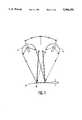
- FIG. 1is a schematic layout of an illumination system of the invention, including a DMD and two illumination sources;
- FIG. 2is a graphical representation of a simple 50 percent duty cycle for synchronously driving a DMD array and two high pressure lamp illumination sources in the arrangement of FIG. 1;
- FIG. 3is a schematic layout of a color sequential projection system using a DMD light valve and an illumination system of the type shown in FIG. 1;
- FIG. 4is a schematic wiring diagram of a DMD element array suitable for use in the invention.
- FIG. 1there is shown a schematic representation of an illumination system of the invention, employing a DMD reflective array 10 and two high pressure discharge lamps, 12 and 14.
- the DMDis a solid state device fabricated from a single piece of silicon, and comprises a matrix array of deformable micromirror elements, each of which can be made to tilt in response to an applied voltage.
- a matrix of electrodes arranged in rows and columnsis used to make individual mirror elements tilt in response to a video signal, to direct reflected light into or out of an optical projection system, and thereby recreate the video image for projection. See, for example, U.S. Pat. Nos. 4,638,309; 4,680,579; and 5,097,544.
- the matrix of electrodesis arranged so that all of the elements in the array are tilted in one direction upon application of a drive voltage, and tilted in another direction upon application of another drive voltage.
- pad electrodes A and B located under opposing sides of each element 40are each connected to the adjacent row and column electrodes, respectively. All of the row electrodes are connected together and subjected to a drive voltage V DMD1 . In turn, all of the column electrodes are connected together and subjected to a drive voltage V DMD2 .
- the elementsare interconnected and subjected to a bias voltage or grounded.
- array 10is shown in elevation view, with the elements 40 shown tilted in the first position and (in phantom) in the second position.
- Lamps 12 and 14are positioned off-axis to illuminate the elements from different directions.
- the lampsshould be positioned so that the illumination beam paths make an angle with the axis approximately twice the angle of deflection of the elements from the plane of the array.
- the deflection angle of the elementsis approximately 10 degrees, and the angle between the illumination beams and the axis is about 20 degrees.
- FIG. 2is a graphical representation of one way of operating the illumination system of the invention, using a 50 percent duty cycle to drive the DMD array, represented by bar graphs (a) and (b), in which drive voltages V DMD1 and V DMD2 alternate in polarity, both of equal amplitude (for example, 20 volts) and duration (for example, about 1/360 second, corresponding to twice the color field rate for a three color sequential system).
- V DMD1 and V DMD2alternate in polarity, both of equal amplitude (for example, 20 volts) and duration (for example, about 1/360 second, corresponding to twice the color field rate for a three color sequential system).
- Bar graphs (c) and (d)represent the duty cycles for the first and second lamps, respectively, in which drive voltages V L1 and V L2 each have a 50 percent duty cycle, with each voltage pulse 180 degrees out of phase with the previous pulse, respectively.
- V L1 and V L2 pulsesalternate with each other, so that V L1 corresponds in time with V DMD1 and V L2 corresponds in time with V DMD2 .
- the light output of the systemis represented by bar graph (e), in which light output from the first and second lamps, L 1 and L 2 , respectively, alternate to result in an effectively continuous light output from the system.
- FIG. 3is a schematic layout of a color television projection system employing an illumination system of the invention.
- Illumination system 30includes DMD reflective array 32, with the array interconnected as shown in FIG. 4, that is, with the deflection electrodes A and B connected to the row and column electrodes, respectively, which are in turn connected to drive voltages V DMD1 and V DMD2 , respectively, supplied alternately by DMD driver 34.
- High pressure discharge lamps 36 and 38are in turn driven alternately by drive voltages V L1 and V L2 from source driver 50 in synchronism with DMD driver 34, in the manner shown in FIG. 2.
- Lamp sources 36 and 38are arranged off-axis to illuminate DMD array 32 at an angle alpha, which is twice the angle of deflection of the DMD elements from the plane of the array, so that both illumination beams are reflected back along the axis of DMD 32, through a rotating color wheel 52.
- Color wheel 52is a transmissive filter having three segments, one for each of the primary colors red, blue and green, so that upon rotation of the wheel, the light from illumination source 30 is sequentially filtered through the red, blue and green filter segments. This filtered light passes into prism 58 of prism illuminator 54, where it is reflected at air gap 60 by total internal reflection to impinge on DMD light valve 62. Unlike DMD array 32 in the illumination source 30, DMD light valve 62 is fabricated in such a manner that each of the deflection elements is individually addressable. In operation, the DMD light valve array is addressed sequentially with red, blue and green video signals from video signal source 64 synchronously with the impingement of the red, blue and green filtered light on the array, to thereby build up a video display image on the array.
- the light reflected from the DMD light valve elements of array 62 in the "on" positionreenters prism 58 and passes out of prism illuminator 54 through air gap 60 and prism 56.
- Such a prism illuminator and its use in an optical systemare known, for example, from U.S. Pat. 4,969,730, issued to A. H. J. van den Brandt.
- the image embodied in the reflected lightenters projection lens 66, where it is magnified and projected onto display screen 68.
- the illumination system of the inventionmay be employed in other color sequential systems, such as the single panel projector with rotating prism of copending U.S. patent application Ser. No. 927,782, filed Aug. 10, 1992 (Attorney's Docket No. PHA 21,648A) and assigned to the present assignee; as well as other color or monochrome projection display systems, such as the three panel color system of Ser. No. 991,216, already referred to above.
- the illumination system of the inventionis useful in other optical systems, particularly those having a narrow acceptance angle, such as fiber optic or other light pipe systems.
Landscapes
- Engineering & Computer Science (AREA)
- Multimedia (AREA)
- Signal Processing (AREA)
- Mechanical Light Control Or Optical Switches (AREA)
- Projection Apparatus (AREA)
- Liquid Crystal (AREA)
- Transforming Electric Information Into Light Information (AREA)
Abstract
Description
This invention relates to illumination systems, and more particularly relates to a two-source illumination system having a high light output.
Light emitted from illumination systems can be modulated by an array of picture elements or pixels whose transmittance or reflectance can be changed in response to an electrical signal, thus creating a display. The modulating array is sometimes referred to as a light valve.
In light valve projection systems, such as those employing LCD panels as light valves, the typical acceptance angle needed to provide an adequate level of display contrast is on the order of plus or minus 15 degrees. In projection systems which are proposed to employ DMD (deformable micromirrored device) panels as light valves, the acceptance angle is even narrower, for example, on the order of plus or minus 10 degrees. Collecting a high percentage of light from a light source over such a restricted collection angle has proven to be difficult in practice.
Light sources which have the combination of small arcs (on the order of 1 to 2 mm in length), high values of luminous efficacy and/or the ability to be driven at high power levels would seem to be the best suited for these demanding applications. However, only two known types of lamps come close to meeting these requirements; a 500 watt xenon arc lamp and a 100 watt high pressure discharge lamp. Both lamps have a small arc of about 1 mm. However, the xenon lamp has a relatively poor luminous efficacy of around 25 lumens per watt, while the high pressure lamp, although it has a somewhat higher luminous efficacy of about 60 lumens per watt, still cannon provide sufficient output to achieve the required brightness levels in the current projection systems employing DMD light valves.
Accordingly, it is an object of the invention to provide an illumination system which has a relatively high light output.
It is another object of the invention to provide such an illumination system which is suitable for use with light valve projection systems.
It is another object of the invention to provide such a system which has a relatively high light output within a relatively narrow acceptance angle.
In accordance with the invention, a two-source illumination system includes: a DMD (digital micromirrored device) having a planar array of reflective deflection elements, the elements deflectable to first and second positions in response to first and second drive voltages; means for causing the elements to cycle periodically between the first and second positions; first and second illumination sources for illuminating the DMD when the elements are in the first and second positions, respectively; as well as means for alternately driving the sources synchronously with the drive means, so that the first source is on when the elements are in the first position and the second source is on when the elements are in the second position.
The DMD drive electrodes are specially configured so that all elements of the array are deflected simultaneously in one direction upon application of the first drive voltage, and deflected simultaneously in the other direction upon application of the second drive voltage. Each source is arranged at an angle to an axis normal to the plane of the array, such that the illumination beams incident on the reflective surface of the DMD are both reflected back between the two sources along the DMD axis. By illuminating the array with the first source when the elements are in the first. position, and illuminating the array with the second source when the elements are in the second position, the light reflected from the array is a combination of the light from both sources.
An advantage of using a DMD reflective array instead of a single reflective element is that the response time of such an array can be very fast, for example, on the order of 10 microseconds, which allows a switching speed more than sufficient to avoid flicker (visual perception of the switching) and/or periodic drop-out artifacts (perception of the failure of individual elements to deflect).
Certain high pressure lamps can have response times as short as 10 microseconds, which is also adequate to avoid flicker and/or drop-out artifacts. A principal advantage of the above arrangement is that the cycling on and off of these high pressure lamps enables driving the lamps at high peak power levels, well above their average power rating, for example at twice their power rating, without appreciably affecting their operating life. Thus, the instantaneous luminous efficacy of each source, and thus the total luminous efficacy of the system, can be nearly doubled when compared to the output of a single source.
Pulsing of high pressure lamp illumination sources to increase light output is known per se. See for example, Philips Technical Review, Vol. 21, 1959/60, No. 3, pp. 73-108. However, the illumination system of the invention allows a near doubling of light output without flicker or drop-out artifacts and without appreciably affecting lamp operating life.
Such an illumination system is particularly useful in projection systems employing light valves having a restricted collection angle, such as LCDs and DMDs.
FIG. 1 is a schematic layout of an illumination system of the invention, including a DMD and two illumination sources;
FIG. 2 is a graphical representation of a simple 50 percent duty cycle for synchronously driving a DMD array and two high pressure lamp illumination sources in the arrangement of FIG. 1;
FIG. 3 is a schematic layout of a color sequential projection system using a DMD light valve and an illumination system of the type shown in FIG. 1; and
FIG. 4 is a schematic wiring diagram of a DMD element array suitable for use in the invention.
Referring now to FIG. 1, there is shown a schematic representation of an illumination system of the invention, employing a DMDreflective array 10 and two high pressure discharge lamps, 12 and 14. The DMD is a solid state device fabricated from a single piece of silicon, and comprises a matrix array of deformable micromirror elements, each of which can be made to tilt in response to an applied voltage.
In a known application of the DMD, a matrix of electrodes arranged in rows and columns is used to make individual mirror elements tilt in response to a video signal, to direct reflected light into or out of an optical projection system, and thereby recreate the video image for projection. See, for example, U.S. Pat. Nos. 4,638,309; 4,680,579; and 5,097,544.
However, in accordance with the present invents on, the matrix of electrodes is arranged so that all of the elements in the array are tilted in one direction upon application of a drive voltage, and tilted in another direction upon application of another drive voltage. For example, in the arrangement shown in plan view in FIG. 4, pad electrodes A and B located under opposing sides of eachelement 40 are each connected to the adjacent row and column electrodes, respectively. All of the row electrodes are connected together and subjected to a drive voltage VDMD1. In turn, all of the column electrodes are connected together and subjected to a drive voltage VDMD2. In addition, the elements are interconnected and subjected to a bias voltage or grounded. By using a simple multiplex switch, not shown, the array can be continuously cycled between the first and second positions, in accordance with, for example, a 50 per cent duty cycle.
Referring again to FIG. 1,array 10 is shown in elevation view, with theelements 40 shown tilted in the first position and (in phantom) in the second position.Lamps
FIG. 2 is a graphical representation of one way of operating the illumination system of the invention, using a 50 percent duty cycle to drive the DMD array, represented by bar graphs (a) and (b), in which drive voltages VDMD1 and VDMD2 alternate in polarity, both of equal amplitude (for example, 20 volts) and duration (for example, about 1/360 second, corresponding to twice the color field rate for a three color sequential system).
Bar graphs (c) and (d) represent the duty cycles for the first and second lamps, respectively, in which drive voltages VL1 and VL2 each have a 50 percent duty cycle, with each voltage pulse 180 degrees out of phase with the previous pulse, respectively. In addition, VL1 and VL2 pulses alternate with each other, so that VL1 corresponds in time with VDMD1 and VL2 corresponds in time with VDMD2. The light output of the system is represented by bar graph (e), in which light output from the first and second lamps, L1 and L2, respectively, alternate to result in an effectively continuous light output from the system.
FIG. 3 is a schematic layout of a color television projection system employing an illumination system of the invention.Illumination system 30 includes DMDreflective array 32, with the array interconnected as shown in FIG. 4, that is, with the deflection electrodes A and B connected to the row and column electrodes, respectively, which are in turn connected to drive voltages VDMD1 and VDMD2, respectively, supplied alternately byDMD driver 34. Highpressure discharge lamps source driver 50 in synchronism withDMD driver 34, in the manner shown in FIG. 2.Lamp sources DMD array 32 at an angle alpha, which is twice the angle of deflection of the DMD elements from the plane of the array, so that both illumination beams are reflected back along the axis ofDMD 32, through a rotatingcolor wheel 52.
The light reflected from the DMD light valve elements ofarray 62 in the "on" position reentersprism 58 and passes out ofprism illuminator 54 throughair gap 60 andprism 56.
Such a prism illuminator and its use in an optical system are known, for example, from U.S. Pat. 4,969,730, issued to A. H. J. van den Brandt.
A full color projection system utilizing three DMDs, each illuminated by a separate prism illuminator, is described and claimed in copending U.S. patent application Ser. No. 991,216, filed Dec. 16, 1992 (Attorney's Docket No. PHA 21,770) and assigned to the present assignee.
Fromprism illuminator 54, the image embodied in the reflected light entersprojection lens 66, where it is magnified and projected ontodisplay screen 68.
Light reflected from the elements ofarray 62 in the "off" position are reflected out of the optical system.
The invention has necessarily been described in terms of a limited number of preferred embodiments. Other embodiments and variations of embodiments will become apparent to the skilled artisan, and are thus intended to be encompassed within the scope of the appended claims. For example, in addition to high pressure discharge lamps, other illumination sources having rapid response times can be employed, such as lasers.
In addition to the color sequential video projection system described, the illumination system of the invention may be employed in other color sequential systems, such as the single panel projector with rotating prism of copending U.S. patent application Ser. No. 927,782, filed Aug. 10, 1992 (Attorney's Docket No. PHA 21,648A) and assigned to the present assignee; as well as other color or monochrome projection display systems, such as the three panel color system of Ser. No. 991,216, already referred to above.
Also, the illumination system of the invention is useful in other optical systems, particularly those having a narrow acceptance angle, such as fiber optic or other light pipe systems.
Claims (12)
1. A two-source illumination system comprising:
(a) a DMD (deformable micromirror device) having a planar array reflective deflection elements, and an axis normal to the plane of the array, the elements being deflectable to a first position in response to a first drive voltage, and being deflectable to a second position in response to a second drive voltage;
(b) voltage drive means for causing the elements to cycle periodically between the first and second positions;
(c) a first illumination source in a first off-axis position for illuminating the DMD when the elements are in the first position;
(d) a second illumination source in a second off-axis position for illuminating the DMD when the elements are in the second position; and;
(e) means for alternately illuminating the sources synchronously with the drive means so that the first source is on when the elements are in the first position and the second source is on when the elements are in the second position,
whereby illumination reflected from the DMD is a combination of illumination from both sources.
2. The illumination system of claim 1 in which the sources are high pressure discharge lamps.
3. The illumination system of claim 1 in which the angle of deflection of the elements from the plane of the array in the first and second positions is about 10 degrees.
4. The illumination system of claim 3 in which the angle between the DMD axis and the beam axes of the illumination sources is about 20 degrees.
5. The illumination system of claim 1 in combination with a projection system comprising at least one light valve, means for addressing the light valve with a display signal, and at least one projection lens, the light valve positioned to reflect illumination from the illumination system into the projection lens, whereby a display image formed in accordance with the display signal is projected by the projection lens.
6. The illumination system of claim 5 in which the projection system is a color sequential television projection system, in which: the light valve is a DMD having a planar array of reflective deflection elements, the elements being individually addressable in response to a video signal; means are provided for sequentially illuminating the DMD with light of the three primary colors red, blue and green; the addressing means includes means for sequentially addressing the DMD with red, blue and green video signals synchronously with illumination of the DMD with the corresponding color of illumination.
7. The illumination system of claim 6 in which a projection display screen is located in front of the projection lens.
8. The illumination system of claim 6 in which the means for sequentially illuminating the DMID with light of the three prima colors comprises a rotatable color wheel.
9. The illumination system of claim 6 in which a prism illuminator is located between the DMD light valve and the projection lens.
10. A DMD comprising a two dimensional array (10) of reflective deflection elements (40), a pair of deflection electrodes (A, B) associated with each deflection element (40), and a matrix of row and column electrodes associated with the deflection electrodes (A, B), characterized in that one electrode (A) of each pair of deflection electrodes is directly connected to a row electrode, the other electrode (B) of each pair of deflection electrodes is directly connected to a column electrode, the row electrodes are interconnected, and the column electrodes are interconnected, so that upon application of a drive voltage to the row electrodes or to the column electrodes, all of the deflection elements of the array are deflected to a first or second deflection position, respectively; and the deflection elements are held at a bias potential or grounded.
11. The illumination system of claim 5 in which the light valve is a DMD.
12. The illumination system of claim 5 in which the light valve is an LCD.
Priority Applications (7)
| Application Number | Priority Date | Filing Date | Title |
|---|---|---|---|
| US08/103,941US5386250A (en) | 1993-08-09 | 1993-08-09 | Two-source illumination system |
| DE69425025TDE69425025T2 (en) | 1993-08-09 | 1994-08-08 | Dual source lighting system |
| JP6185877AJPH07152032A (en) | 1993-08-09 | 1994-08-08 | 2-light-source illuminator |
| CN94109395ACN1054923C (en) | 1993-08-09 | 1994-08-08 | Two-source illumination system |
| EP94202277AEP0640858B1 (en) | 1993-08-09 | 1994-08-08 | Two-source illumination system |
| SG1996009191ASG55178A1 (en) | 1993-08-09 | 1994-08-08 | Two-source illumination system |
| TW083107734ATW254000B (en) | 1993-08-09 | 1994-08-23 |
Applications Claiming Priority (1)
| Application Number | Priority Date | Filing Date | Title |
|---|---|---|---|
| US08/103,941US5386250A (en) | 1993-08-09 | 1993-08-09 | Two-source illumination system |
Publications (1)
| Publication Number | Publication Date |
|---|---|
| US5386250Atrue US5386250A (en) | 1995-01-31 |
Family
ID=22297822
Family Applications (1)
| Application Number | Title | Priority Date | Filing Date |
|---|---|---|---|
| US08/103,941Expired - Fee RelatedUS5386250A (en) | 1993-08-09 | 1993-08-09 | Two-source illumination system |
Country Status (7)
| Country | Link |
|---|---|
| US (1) | US5386250A (en) |
| EP (1) | EP0640858B1 (en) |
| JP (1) | JPH07152032A (en) |
| CN (1) | CN1054923C (en) |
| DE (1) | DE69425025T2 (en) |
| SG (1) | SG55178A1 (en) |
| TW (1) | TW254000B (en) |
Cited By (43)
| Publication number | Priority date | Publication date | Assignee | Title |
|---|---|---|---|---|
| AU674619B2 (en)* | 1994-12-15 | 1997-01-02 | Jack Newman | Stereoscopic micromirror display |
| US5612753A (en)* | 1995-01-27 | 1997-03-18 | Texas Instruments Incorporated | Full-color projection display system using two light modulators |
| US5640214A (en)* | 1994-09-30 | 1997-06-17 | Texas Instruments Incorporated | Printer and display systems with bidirectional light collection structures |
| US5654775A (en)* | 1995-12-27 | 1997-08-05 | Philips Electronics North America Corporation | Three lamp, three light valve projection system |
| WO1997024871A3 (en)* | 1995-12-27 | 1997-08-21 | Philips Electronics Nv | Two lamp, single light valve projection system |
| EP0740178A3 (en)* | 1995-04-26 | 1997-11-19 | Texas Instruments Incorporated | Improvements relating to illumination optics for light modulator |
| EP0766481A3 (en)* | 1995-09-29 | 1997-11-19 | Matsushita Electric Industrial Co., Ltd. | Projection display |
| EP0773691A3 (en)* | 1995-11-10 | 1997-12-29 | Hitachi, Ltd. | Liquid crystal projector |
| US5706061A (en)* | 1995-03-31 | 1998-01-06 | Texas Instruments Incorporated | Spatial light image display system with synchronized and modulated light source |
| US5788352A (en)* | 1994-10-25 | 1998-08-04 | Hughes Aircraft Company | Multiplexed multi-image source display writing system |
| WO1998028655A3 (en)* | 1996-12-20 | 1998-10-08 | Biophysica Technologies Inc | Light modulated confocal optical instruments and method |
| EP0879437A4 (en)* | 1996-02-07 | 2000-03-29 | Light & Sound Design Ltd | PROGRAMMABLE DEVICE MODIFYING THE SHAPE OF A LIGHT BEAM USING PROGRAMMABLE MICROMIRRORS |
| EP0865210A3 (en)* | 1997-03-12 | 2001-01-17 | Texas Instruments Incorporated | Improvements in or relating to display systems |
| WO2000065399A3 (en)* | 1999-04-23 | 2001-01-18 | Koninkl Philips Electronics Nv | Projection system |
| US6288828B1 (en) | 1997-09-10 | 2001-09-11 | Light And Sound Design Ltd. | Programmable light beam shape altering device using programmable micromirrors |
| US20010036003A1 (en)* | 1998-11-23 | 2001-11-01 | Light And Sound Design Ltd. | Programmable light beam shape altering device using separate programmable micromirrors for each primary color |
| US6348907B1 (en) | 1989-08-22 | 2002-02-19 | Lawson A. Wood | Display apparatus with digital micromirror device |
| EP1033614A3 (en)* | 1999-03-02 | 2002-05-15 | Seiko Epson Corporation | Projector using an electro-optic modulator and a prism |
| US6421165B2 (en) | 1996-02-07 | 2002-07-16 | Light & Sound Design Ltd. | Programmable light beam shape altering device using programmable micromirrors |
| US20020093477A1 (en)* | 1995-01-31 | 2002-07-18 | Wood Lawson A. | Display apparatus and method |
| EP1219978A3 (en)* | 2000-12-29 | 2002-07-24 | Lg Electronics Inc. | Total reflection prism and reflection type projector using such a prism |
| US20030107893A1 (en)* | 2001-12-12 | 2003-06-12 | Samsung Electronics Co., Ltd. | Image projection apparatus and method |
| EP1432244A1 (en)* | 2002-12-20 | 2004-06-23 | Eastman Kodak Company | Compensating for pixel defects by spatial translation of scene content |
| US20040218149A1 (en)* | 2000-08-30 | 2004-11-04 | Huibers Andrew G. | Projection display |
| US20040218292A1 (en)* | 2001-08-03 | 2004-11-04 | Huibers Andrew G | Micromirror array for projection TV |
| US20040233679A1 (en)* | 2003-05-21 | 2004-11-25 | Ferri John M. | System and method for providing a uniform source of light |
| US20050179982A1 (en)* | 2000-12-07 | 2005-08-18 | Patel Satyadev R. | Methods for depositing, releasing and packaging micro-electromechanical devices on wafer substrates |
| US6962419B2 (en) | 1998-09-24 | 2005-11-08 | Reflectivity, Inc | Micromirror elements, package for the micromirror elements, and projection system therefor |
| US20060007522A1 (en)* | 2003-10-30 | 2006-01-12 | Andrew Huibers | Micromirror and post arrangements on substrates |
| US20060120099A1 (en)* | 2004-12-06 | 2006-06-08 | Texas Instruments Incorporated | Multiple light source illumination for image display systems |
| US20060214896A1 (en)* | 2003-05-06 | 2006-09-28 | Fumiaki Yamada | Matrix driven liquid crystal display module system, apparatus and method |
| US20060274288A1 (en)* | 2005-06-02 | 2006-12-07 | 3M Innovative Properties Company | Multiple location illumination system and projection display system employing same |
| US20080158245A1 (en)* | 2006-12-29 | 2008-07-03 | Texas Instruments Incorporated | High dynamic range display systems |
| US20080158641A1 (en)* | 2006-12-29 | 2008-07-03 | Texas Instruments Incorporated | Backlight unit and an imaging system using the same |
| EP1898679A3 (en)* | 1997-05-12 | 2008-07-23 | Light & Sound Design, Ltd. | Electronically controlled stage lighting system |
| US20090175577A1 (en)* | 2001-01-29 | 2009-07-09 | Production Resource Group L.L.C | Three Color Digital Gobo System |
| US20100201289A1 (en)* | 2009-02-12 | 2010-08-12 | Charalampos Pozidis | High-speed electrostatic actuation of mems-based devices |
| EP1902339A4 (en)* | 2004-08-26 | 2010-09-08 | Texas Instruments Inc | Multiple path illumination for image display systems |
| US20110216321A1 (en)* | 2010-03-04 | 2011-09-08 | Canon Kabushiki Kaisha | Projection display apparatus having plural light sources |
| US9310054B2 (en) | 2011-01-21 | 2016-04-12 | Osram Gmbh | Internally cooled fluorescent device and reflector lamp arrangement including said fluorescent device |
| US10230928B2 (en) | 2014-10-27 | 2019-03-12 | Texas Instruments Incorporated | Color recapture using polarization recovery in a color-field sequential display system |
| US10967779B2 (en) | 2017-11-02 | 2021-04-06 | Bayerische Motoren Werke Aktiengesellschaft | Lighting apparatus for a motor vehicle |
| US11060681B2 (en) | 2017-11-02 | 2021-07-13 | Bayerische Motoren Werke Aktiengesellschaft | Lighting apparatus for a motor vehicle |
Families Citing this family (7)
| Publication number | Priority date | Publication date | Assignee | Title |
|---|---|---|---|---|
| WO1997001128A1 (en)* | 1995-06-22 | 1997-01-09 | Optica Nova Onab Ab | Illumination arrangement for projection with reflective displays |
| CA2314163C (en)* | 1997-12-17 | 2008-09-23 | Color Kinetics Incorporated | Digitally controlled illumination methods and systems |
| JP4561808B2 (en)* | 2002-03-22 | 2010-10-13 | セイコーエプソン株式会社 | Image display device and projector |
| JP4055610B2 (en) | 2002-03-22 | 2008-03-05 | セイコーエプソン株式会社 | Image display device and projector |
| DE102006045692A1 (en)* | 2006-09-27 | 2008-04-03 | Osram Opto Semiconductors Gmbh | Optical projection device has two light sources with light-emitting diode chip, and numbers of micro mirrors are arranged to micro mirror field |
| US20090303444A1 (en)* | 2008-06-04 | 2009-12-10 | Delta Electronics, Inc. | Projection System |
| US9485491B2 (en) | 2014-12-15 | 2016-11-01 | Test Research, Inc. | Optical system |
Citations (7)
| Publication number | Priority date | Publication date | Assignee | Title |
|---|---|---|---|---|
| US4638309A (en)* | 1983-09-08 | 1987-01-20 | Texas Instruments Incorporated | Spatial light modulator drive system |
| US4680579A (en)* | 1983-09-08 | 1987-07-14 | Texas Instruments Incorporated | Optical system for projection display using spatial light modulator device |
| US4879602A (en)* | 1987-09-04 | 1989-11-07 | New York Institute Of Technology | Electrode patterns for solid state light modulator |
| US4969730A (en)* | 1988-10-13 | 1990-11-13 | U.S. Philips Corporation | Image projection arrangement |
| US5096279A (en)* | 1984-08-31 | 1992-03-17 | Texas Instruments Incorporated | Spatial light modulator and method |
| US5097544A (en)* | 1991-07-02 | 1992-03-24 | Castro Convertible Corporation | Convertible sofa bed |
| US5212555A (en)* | 1991-12-17 | 1993-05-18 | Texas Instruments Incorporated | Image capture with spatial light modulator and single-cell photosensor |
Family Cites Families (4)
| Publication number | Priority date | Publication date | Assignee | Title |
|---|---|---|---|---|
| JPS60165783A (en)* | 1984-02-08 | 1985-08-28 | Toshiba Corp | Dye laser device |
| JPS62127707A (en)* | 1985-11-28 | 1987-06-10 | Canon Inc | color printer |
| US4859012A (en)* | 1987-08-14 | 1989-08-22 | Texas Instruments Incorporated | Optical interconnection networks |
| US5231388A (en)* | 1991-12-17 | 1993-07-27 | Texas Instruments Incorporated | Color display system using spatial light modulators |
- 1993
- 1993-08-09USUS08/103,941patent/US5386250A/ennot_activeExpired - Fee Related
- 1994
- 1994-08-08JPJP6185877Apatent/JPH07152032A/ennot_activeCeased
- 1994-08-08EPEP94202277Apatent/EP0640858B1/ennot_activeExpired - Lifetime
- 1994-08-08CNCN94109395Apatent/CN1054923C/ennot_activeExpired - Fee Related
- 1994-08-08SGSG1996009191Apatent/SG55178A1/enunknown
- 1994-08-08DEDE69425025Tpatent/DE69425025T2/ennot_activeExpired - Fee Related
- 1994-08-23TWTW083107734Apatent/TW254000B/zhactive
Patent Citations (7)
| Publication number | Priority date | Publication date | Assignee | Title |
|---|---|---|---|---|
| US4638309A (en)* | 1983-09-08 | 1987-01-20 | Texas Instruments Incorporated | Spatial light modulator drive system |
| US4680579A (en)* | 1983-09-08 | 1987-07-14 | Texas Instruments Incorporated | Optical system for projection display using spatial light modulator device |
| US5096279A (en)* | 1984-08-31 | 1992-03-17 | Texas Instruments Incorporated | Spatial light modulator and method |
| US4879602A (en)* | 1987-09-04 | 1989-11-07 | New York Institute Of Technology | Electrode patterns for solid state light modulator |
| US4969730A (en)* | 1988-10-13 | 1990-11-13 | U.S. Philips Corporation | Image projection arrangement |
| US5097544A (en)* | 1991-07-02 | 1992-03-24 | Castro Convertible Corporation | Convertible sofa bed |
| US5212555A (en)* | 1991-12-17 | 1993-05-18 | Texas Instruments Incorporated | Image capture with spatial light modulator and single-cell photosensor |
Non-Patent Citations (6)
| Title |
|---|
| Philips Technical Review, vol. 21, 1969/60, No. 3, pp. 73 108.* |
| Philips Technical Review, vol. 21, 1969/60, No. 3, pp. 73-108. |
| Ser. No. 927,782, filed Aug. 10, 1992 (Attorney s Docket No. PHA 21,648A).* |
| Ser. No. 927,782, filed Aug. 10, 1992 (Attorney's Docket No. PHA 21,648A). |
| Ser. No. 991,216 filed Dec. 16, 1992 (Attorney s Docket No PHA 21,770).* |
| Ser. No. 991,216 filed Dec. 16, 1992 (Attorney's Docket No PHA 21,770). |
Cited By (113)
| Publication number | Priority date | Publication date | Assignee | Title |
|---|---|---|---|---|
| US6348907B1 (en) | 1989-08-22 | 2002-02-19 | Lawson A. Wood | Display apparatus with digital micromirror device |
| US5640214A (en)* | 1994-09-30 | 1997-06-17 | Texas Instruments Incorporated | Printer and display systems with bidirectional light collection structures |
| US5788352A (en)* | 1994-10-25 | 1998-08-04 | Hughes Aircraft Company | Multiplexed multi-image source display writing system |
| AU674619B2 (en)* | 1994-12-15 | 1997-01-02 | Jack Newman | Stereoscopic micromirror display |
| US5612753A (en)* | 1995-01-27 | 1997-03-18 | Texas Instruments Incorporated | Full-color projection display system using two light modulators |
| US20020093477A1 (en)* | 1995-01-31 | 2002-07-18 | Wood Lawson A. | Display apparatus and method |
| US7782280B2 (en) | 1995-01-31 | 2010-08-24 | Acacia Patent Acquisition Corporation | Display apparatus and method |
| US7253794B2 (en) | 1995-01-31 | 2007-08-07 | Acacia Patent Acquisition Corporation | Display apparatus and method |
| US20060250336A1 (en)* | 1995-01-31 | 2006-11-09 | Wood Lawson A | Display apparatus and method |
| US5706061A (en)* | 1995-03-31 | 1998-01-06 | Texas Instruments Incorporated | Spatial light image display system with synchronized and modulated light source |
| US5796526A (en)* | 1995-04-26 | 1998-08-18 | Texas Instruments Incorporated | Illumination optics for spatial light modulator |
| EP0740178A3 (en)* | 1995-04-26 | 1997-11-19 | Texas Instruments Incorporated | Improvements relating to illumination optics for light modulator |
| EP0766481A3 (en)* | 1995-09-29 | 1997-11-19 | Matsushita Electric Industrial Co., Ltd. | Projection display |
| EP0773691A3 (en)* | 1995-11-10 | 1997-12-29 | Hitachi, Ltd. | Liquid crystal projector |
| EP0773691B1 (en)* | 1995-11-10 | 2002-07-24 | Hitachi, Ltd. | Liquid crystal projector |
| US6147720A (en)* | 1995-12-27 | 2000-11-14 | Philips Electronics North America Corporation | Two lamp, single light valve projection system |
| WO1997024871A3 (en)* | 1995-12-27 | 1997-08-21 | Philips Electronics Nv | Two lamp, single light valve projection system |
| US5654775A (en)* | 1995-12-27 | 1997-08-05 | Philips Electronics North America Corporation | Three lamp, three light valve projection system |
| EP1445637A3 (en)* | 1996-02-07 | 2004-10-27 | Light & Sound Design, Ltd. | A programmable light beam shape altering device using programmable micromirrors |
| EP1855143A3 (en)* | 1996-02-07 | 2008-01-16 | Light & Sound Design, Ltd. | A programmable light beam shape altering device using programmable micromirrors |
| US6421165B2 (en) | 1996-02-07 | 2002-07-16 | Light & Sound Design Ltd. | Programmable light beam shape altering device using programmable micromirrors |
| EP0879437A4 (en)* | 1996-02-07 | 2000-03-29 | Light & Sound Design Ltd | PROGRAMMABLE DEVICE MODIFYING THE SHAPE OF A LIGHT BEAM USING PROGRAMMABLE MICROMIRRORS |
| US7224509B2 (en) | 1996-02-07 | 2007-05-29 | Production Resource Group, L.L.C. | Programmable light beam shape altering device using programmable micromirrors |
| US8976441B2 (en) | 1996-02-07 | 2015-03-10 | Production Resource Group, Llc | Programmable light beam shape altering device using programmable micromirrors |
| EP1830220A2 (en)* | 1996-02-07 | 2007-09-05 | Light & Sound Design, Ltd. | A programmable light beam shape altering device using programmable micromirrors |
| US20070211469A1 (en)* | 1996-02-07 | 2007-09-13 | Production Resource Group, L.L.C. | Programmable light beam shape altering device using programmable micromirrors |
| US20030147117A1 (en)* | 1996-02-07 | 2003-08-07 | Light & Sound Design Ltd., A Great Britain Corporation | Programmable light beam shape altering device using programmable micromirrors |
| US7515367B2 (en) | 1996-02-07 | 2009-04-07 | Production Resource Group, Llc | Method of controlling a lighting device |
| US8009374B2 (en) | 1996-02-07 | 2011-08-30 | Production Resource Group, Llc | Programmable light beam shape altering device using programmable micromirrors |
| US6771411B2 (en) | 1996-02-07 | 2004-08-03 | Production Resource Group Inc. | Programmable light beam shape altering device using programmable micromirrors |
| US7535622B2 (en) | 1996-02-07 | 2009-05-19 | Production Resource Group, Llc | Programmable light beam shape altering device using programmable micromirrors |
| EP1443355A3 (en)* | 1996-02-07 | 2004-10-27 | Light & Sound Design, Ltd. | A programmable light beam shape altering device using programmable micromirrors |
| EP1447701A3 (en)* | 1996-02-07 | 2004-10-27 | Light & Sound Design, Ltd. | A programmable light beam shape altering device using programmable micromirrors |
| US20090190203A1 (en)* | 1996-02-07 | 2009-07-30 | Production Resource Group L.L.C | Programmable light beam shape altering device using programmable micromirrors |
| EP1447702A3 (en)* | 1996-02-07 | 2004-10-27 | Light & Sound Design, Ltd. | A programmable light beam shape altering device using programmable micromirrors |
| EP1450197A3 (en)* | 1996-02-07 | 2004-10-27 | Light & Sound Design, Ltd. | A programmable light beam shape altering device using programmable micromirrors |
| WO1998028655A3 (en)* | 1996-12-20 | 1998-10-08 | Biophysica Technologies Inc | Light modulated confocal optical instruments and method |
| EP0865210A3 (en)* | 1997-03-12 | 2001-01-17 | Texas Instruments Incorporated | Improvements in or relating to display systems |
| EP1898679A3 (en)* | 1997-05-12 | 2008-07-23 | Light & Sound Design, Ltd. | Electronically controlled stage lighting system |
| US6288828B1 (en) | 1997-09-10 | 2001-09-11 | Light And Sound Design Ltd. | Programmable light beam shape altering device using programmable micromirrors |
| US6962419B2 (en) | 1998-09-24 | 2005-11-08 | Reflectivity, Inc | Micromirror elements, package for the micromirror elements, and projection system therefor |
| US8022954B2 (en) | 1998-11-23 | 2011-09-20 | Production Resource Group, L.L.C | Programmable light beam shape altering device using separate programmable micromirrors for each primary color |
| US8314800B2 (en) | 1998-11-23 | 2012-11-20 | Production Resource Group Inc. | Programmable light beam shape altering device using separate programmable micromirrors for each primary color |
| US20010036003A1 (en)* | 1998-11-23 | 2001-11-01 | Light And Sound Design Ltd. | Programmable light beam shape altering device using separate programmable micromirrors for each primary color |
| EP1033614A3 (en)* | 1999-03-02 | 2002-05-15 | Seiko Epson Corporation | Projector using an electro-optic modulator and a prism |
| US6556256B1 (en) | 1999-03-02 | 2003-04-29 | Seiko Epson Corporation | Projector and prism used therein |
| WO2000065399A3 (en)* | 1999-04-23 | 2001-01-18 | Koninkl Philips Electronics Nv | Projection system |
| US7012731B2 (en) | 2000-08-30 | 2006-03-14 | Reflectivity, Inc | Packaged micromirror array for a projection display |
| US7262817B2 (en) | 2000-08-30 | 2007-08-28 | Texas Instruments Incorporated | Rear projection TV with improved micromirror array |
| US20040218293A1 (en)* | 2000-08-30 | 2004-11-04 | Huibers Andrew G. | Packaged micromirror array for a projection display |
| US20040223088A1 (en)* | 2000-08-30 | 2004-11-11 | Huibers Andrew G. | Projection TV with improved micromirror array |
| US7300162B2 (en) | 2000-08-30 | 2007-11-27 | Texas Instruments Incorporated | Projection display |
| US20040233392A1 (en)* | 2000-08-30 | 2004-11-25 | Huibers Andrew G. | Projection TV with improved micromirror array |
| US20040218154A1 (en)* | 2000-08-30 | 2004-11-04 | Huibers Andrew G. | Packaged micromirror array for a projection display |
| US20050030490A1 (en)* | 2000-08-30 | 2005-02-10 | Huibers Andrew G. | Projection display |
| US7196740B2 (en)* | 2000-08-30 | 2007-03-27 | Texas Instruments Incorporated | Projection TV with improved micromirror array |
| US7006275B2 (en) | 2000-08-30 | 2006-02-28 | Reflectivity, Inc | Packaged micromirror array for a projection display |
| US7172296B2 (en) | 2000-08-30 | 2007-02-06 | Reflectivity, Inc | Projection display |
| US7018052B2 (en) | 2000-08-30 | 2006-03-28 | Reflectivity, Inc | Projection TV with improved micromirror array |
| US7167297B2 (en) | 2000-08-30 | 2007-01-23 | Reflectivity, Inc | Micromirror array |
| US20040218149A1 (en)* | 2000-08-30 | 2004-11-04 | Huibers Andrew G. | Projection display |
| US7655492B2 (en) | 2000-12-07 | 2010-02-02 | Texas Instruments Incorporated | Methods for depositing, releasing and packaging micro-electromechanical devices on wafer substrates |
| US20050214976A1 (en)* | 2000-12-07 | 2005-09-29 | Patel Satyadev R | Methods for depositing, releasing and packaging micro-electromechanical devices on wafer substrates |
| US20050179982A1 (en)* | 2000-12-07 | 2005-08-18 | Patel Satyadev R. | Methods for depositing, releasing and packaging micro-electromechanical devices on wafer substrates |
| US20050191790A1 (en)* | 2000-12-07 | 2005-09-01 | Patel Satyadev R. | Methods for depositing, releasing and packaging micro-electromechanical devices on wafer substrates |
| US20050191789A1 (en)* | 2000-12-07 | 2005-09-01 | Patel Satyadev R. | Methods for depositing, releasing and packaging micro-electromechanical devices on wafer substrates |
| US20070001247A1 (en)* | 2000-12-07 | 2007-01-04 | Patel Satyadev R | Methods for depositing, releasing and packaging micro-electromechanical devices on wafer substrates |
| US7573111B2 (en) | 2000-12-07 | 2009-08-11 | Texas Instruments Incorporated | Methods for depositing, releasing and packaging micro-electromechanical devices on wafer substrates |
| US20050181532A1 (en)* | 2000-12-07 | 2005-08-18 | Patel Satyadev R. | Methods for depositing, releasing and packaging micro-electromechanical devices on wafer substrates |
| US7671428B2 (en) | 2000-12-07 | 2010-03-02 | Texas Instruments Incorporated | Methods for depositing, releasing and packaging micro-electromechanical devices on wafer substrates |
| US20050180686A1 (en)* | 2000-12-07 | 2005-08-18 | Patel Satyadev R. | Methods for depositing, releasing and packaging micro-electromechanical devices on wafer substrates |
| US7286278B2 (en) | 2000-12-07 | 2007-10-23 | Texas Instruments Incorporated | Methods for depositing, releasing and packaging micro-electromechanical devices on wafer substrates |
| US20050260793A1 (en)* | 2000-12-07 | 2005-11-24 | Patel Satyadev R | Methods for depositing, releasing and packaging micro-electromechanical devices on wafer substrates |
| EP1219978A3 (en)* | 2000-12-29 | 2002-07-24 | Lg Electronics Inc. | Total reflection prism and reflection type projector using such a prism |
| US6644815B2 (en) | 2000-12-29 | 2003-11-11 | Lg Electronics Inc. | Total reflection prism and projector with the same |
| US20090175577A1 (en)* | 2001-01-29 | 2009-07-09 | Production Resource Group L.L.C | Three Color Digital Gobo System |
| US20100188019A1 (en)* | 2001-01-29 | 2010-07-29 | Production Resource Group L.L.C | Three Color Digital Gobo System |
| US8094981B2 (en) | 2001-01-29 | 2012-01-10 | Production Resource Group, L.C.C | Three color digital gobo system |
| US7693368B2 (en)* | 2001-01-29 | 2010-04-06 | Production Resource Group, Llc | Three color digital gobo system |
| US7023606B2 (en) | 2001-08-03 | 2006-04-04 | Reflectivity, Inc | Micromirror array for projection TV |
| US20040218292A1 (en)* | 2001-08-03 | 2004-11-04 | Huibers Andrew G | Micromirror array for projection TV |
| US6796689B2 (en)* | 2001-12-12 | 2004-09-28 | Samsung Electronics Co., Ltd. | Image projection apparatus and method |
| US20030107893A1 (en)* | 2001-12-12 | 2003-06-12 | Samsung Electronics Co., Ltd. | Image projection apparatus and method |
| EP1432244A1 (en)* | 2002-12-20 | 2004-06-23 | Eastman Kodak Company | Compensating for pixel defects by spatial translation of scene content |
| US20060214896A1 (en)* | 2003-05-06 | 2006-09-28 | Fumiaki Yamada | Matrix driven liquid crystal display module system, apparatus and method |
| US7679614B2 (en)* | 2003-05-06 | 2010-03-16 | Au Optronics Corporation | Matrix driven liquid crystal display module system, apparatus and method |
| US20040233679A1 (en)* | 2003-05-21 | 2004-11-25 | Ferri John M. | System and method for providing a uniform source of light |
| WO2004106980A3 (en)* | 2003-05-21 | 2005-05-12 | Advanced Digital Optics Inc | System and method for providing a uniform source of light |
| US6953275B2 (en)* | 2003-05-21 | 2005-10-11 | Jds Uniphase Corporation | System and method for providing a uniform source of light |
| US7362493B2 (en) | 2003-10-30 | 2008-04-22 | Texas Instruments Incorporated | Micromirror and post arrangements on substrates |
| US7075702B2 (en) | 2003-10-30 | 2006-07-11 | Reflectivity, Inc | Micromirror and post arrangements on substrates |
| US20060018003A1 (en)* | 2003-10-30 | 2006-01-26 | Andrew Huibers | Micromirror and post arrangements on substrates |
| US20060007522A1 (en)* | 2003-10-30 | 2006-01-12 | Andrew Huibers | Micromirror and post arrangements on substrates |
| EP1902339A4 (en)* | 2004-08-26 | 2010-09-08 | Texas Instruments Inc | Multiple path illumination for image display systems |
| WO2006124070A1 (en)* | 2004-12-06 | 2006-11-23 | Texas Instruments Incorporated | Multiple light source illumination for image display systems |
| US7364326B2 (en) | 2004-12-06 | 2008-04-29 | Texas Instruments Incorporated | Multiple light source illumination for image display systems |
| US20060120099A1 (en)* | 2004-12-06 | 2006-06-08 | Texas Instruments Incorporated | Multiple light source illumination for image display systems |
| KR100928366B1 (en) | 2004-12-06 | 2009-11-23 | 텍사스 인스트루먼츠 인코포레이티드 | Image Display Devices, and How to Pass Light From an Image Display System |
| EP1886185A4 (en)* | 2005-06-02 | 2009-07-15 | 3M Innovative Properties Co | Multiple location illumination system and projection display system employing same |
| US7503659B2 (en) | 2005-06-02 | 2009-03-17 | 3M Innovative Properties Company | Multiple location illumination system and projection display system employing same |
| US20060274288A1 (en)* | 2005-06-02 | 2006-12-07 | 3M Innovative Properties Company | Multiple location illumination system and projection display system employing same |
| US20080158641A1 (en)* | 2006-12-29 | 2008-07-03 | Texas Instruments Incorporated | Backlight unit and an imaging system using the same |
| US20080158245A1 (en)* | 2006-12-29 | 2008-07-03 | Texas Instruments Incorporated | High dynamic range display systems |
| US8542408B2 (en) | 2006-12-29 | 2013-09-24 | Texas Instruments Incorporated | High dynamic range display systems |
| US8395877B2 (en)* | 2009-02-12 | 2013-03-12 | International Business Machines Corporation | High-speed electrostatic actuation of MEMS-based devices |
| US20100201289A1 (en)* | 2009-02-12 | 2010-08-12 | Charalampos Pozidis | High-speed electrostatic actuation of mems-based devices |
| EP2367055A1 (en)* | 2010-03-04 | 2011-09-21 | Canon Kabushiki Kaisha | Projection display apparatus |
| US20110216321A1 (en)* | 2010-03-04 | 2011-09-08 | Canon Kabushiki Kaisha | Projection display apparatus having plural light sources |
| US8491130B2 (en) | 2010-03-04 | 2013-07-23 | Canon Kabushiki Kaisha | Projection display apparatus having plural light sources |
| US9310054B2 (en) | 2011-01-21 | 2016-04-12 | Osram Gmbh | Internally cooled fluorescent device and reflector lamp arrangement including said fluorescent device |
| US10230928B2 (en) | 2014-10-27 | 2019-03-12 | Texas Instruments Incorporated | Color recapture using polarization recovery in a color-field sequential display system |
| US10967779B2 (en) | 2017-11-02 | 2021-04-06 | Bayerische Motoren Werke Aktiengesellschaft | Lighting apparatus for a motor vehicle |
| US11060681B2 (en) | 2017-11-02 | 2021-07-13 | Bayerische Motoren Werke Aktiengesellschaft | Lighting apparatus for a motor vehicle |
Also Published As
| Publication number | Publication date |
|---|---|
| DE69425025T2 (en) | 2001-02-22 |
| JPH07152032A (en) | 1995-06-16 |
| DE69425025D1 (en) | 2000-08-03 |
| EP0640858A2 (en) | 1995-03-01 |
| CN1054923C (en) | 2000-07-26 |
| EP0640858B1 (en) | 2000-06-28 |
| CN1111359A (en) | 1995-11-08 |
| SG55178A1 (en) | 1999-09-21 |
| TW254000B (en) | 1995-08-11 |
| EP0640858A3 (en) | 1995-07-12 |
Similar Documents
| Publication | Publication Date | Title |
|---|---|---|
| US5386250A (en) | Two-source illumination system | |
| US5402184A (en) | Projection system having image oscillation | |
| US6252636B1 (en) | Pulsed two lamp single light valve display system | |
| US5353133A (en) | A display having a standard or reversed schieren microprojector at each picture element | |
| US7997737B2 (en) | Projection display device, and speckle reduction element | |
| EP0704737B1 (en) | Optical system for printers and display systems | |
| US6824270B2 (en) | Single-panel color image display apparatus and scrolling method | |
| JPH1068997A (en) | Picture projector | |
| JPH05273516A (en) | Image projection system | |
| JPH11505334A (en) | Projection device | |
| US7492378B2 (en) | Image display system implements a light source with a controllable schedule to emit light of adjustable intensities | |
| KR20020027580A (en) | High contrast polarizing optics for a color electro-optic display device | |
| US7118226B2 (en) | Sequential color recapture for image display systems | |
| JP2003121933A (en) | Projection device | |
| US20100103499A1 (en) | Biaxial mirror color selecting micro mirror imager | |
| US6128049A (en) | Use of shutter to control the illumination period in a ferroelectric liquid crystal-based spatial light modulator display device | |
| WO2008050238A2 (en) | Increase gray scales of projection system by reflecting light from mirror elements with non-uniform intensity distribution | |
| US6902276B2 (en) | Color projector apparatus and method | |
| US6666558B1 (en) | Projection image display | |
| CN1188728C (en) | Image Projection system | |
| US20100110529A1 (en) | Biaxial mirror color selecting micro imager | |
| US20060126021A1 (en) | Scrolling color system with ac-operated lamp | |
| JP2005043431A (en) | Illumination device and color image display device using the same | |
| KR20050050644A (en) | Pulse width modulated display with hybrid coding | |
| WO2005076070A1 (en) | Color projector apparatus and method |
Legal Events
| Date | Code | Title | Description |
|---|---|---|---|
| AS | Assignment | Owner name:PHILIPS ELECTRONICS NORTH AMERICA CORPORATION, NEW Free format text:ASSIGNMENT OF ASSIGNORS INTEREST;ASSIGNOR:GUERINOT, WILLIAM F.;REEL/FRAME:006660/0060 Effective date:19930805 | |
| FPAY | Fee payment | Year of fee payment:4 | |
| REMI | Maintenance fee reminder mailed | ||
| LAPS | Lapse for failure to pay maintenance fees | ||
| FP | Lapsed due to failure to pay maintenance fee | Effective date:20030131 | |
| STCH | Information on status: patent discontinuation | Free format text:PATENT EXPIRED DUE TO NONPAYMENT OF MAINTENANCE FEES UNDER 37 CFR 1.362 |