US5385576A - Method for detecting ventricular fibrillation and apparatus for detecting and treating ventricular fibrillation - Google Patents
Method for detecting ventricular fibrillation and apparatus for detecting and treating ventricular fibrillationDownload PDFInfo
- Publication number
- US5385576A US5385576AUS08/101,727US10172793AUS5385576AUS 5385576 AUS5385576 AUS 5385576AUS 10172793 AUS10172793 AUS 10172793AUS 5385576 AUS5385576 AUS 5385576A
- Authority
- US
- United States
- Prior art keywords
- heart
- impedance signal
- ventricular fibrillation
- measured impedance
- level
- Prior art date
- Legal status (The legal status is an assumption and is not a legal conclusion. Google has not performed a legal analysis and makes no representation as to the accuracy of the status listed.)
- Expired - Lifetime
Links
- 208000003663ventricular fibrillationDiseases0.000titleclaimsabstractdescription44
- 238000000034methodMethods0.000titleclaimsabstractdescription17
- 230000001419dependent effectEffects0.000claimsabstractdescription14
- 239000008280bloodSubstances0.000claimsabstractdescription13
- 210000004369bloodAnatomy0.000claimsabstractdescription13
- 238000011156evaluationMethods0.000claimsdescription27
- 230000000638stimulationEffects0.000claimsdescription27
- 238000012935AveragingMethods0.000claimsdescription3
- 238000012544monitoring processMethods0.000claims2
- 230000007423decreaseEffects0.000abstractdescription2
- 230000008447perceptionEffects0.000abstractdescription2
- 230000000694effectsEffects0.000description13
- 238000001514detection methodMethods0.000description12
- 230000008602contractionEffects0.000description7
- 206010049447TachyarrhythmiaDiseases0.000description4
- 208000001871TachycardiaDiseases0.000description4
- 230000000747cardiac effectEffects0.000description3
- 238000005259measurementMethods0.000description3
- 210000004165myocardiumAnatomy0.000description3
- 238000005086pumpingMethods0.000description3
- 230000033764rhythmic processEffects0.000description3
- 238000010586diagramMethods0.000description2
- 238000002847impedance measurementMethods0.000description2
- 238000012986modificationMethods0.000description2
- 230000004048modificationEffects0.000description2
- 230000007170pathologyEffects0.000description2
- 230000004044responseEffects0.000description2
- 238000002560therapeutic procedureMethods0.000description2
- 206010028347Muscle twitchingDiseases0.000description1
- 238000013194cardioversionMethods0.000description1
- 230000008859changeEffects0.000description1
- 230000002708enhancing effectEffects0.000description1
- 230000001747exhibiting effectEffects0.000description1
- 230000006870functionEffects0.000description1
- 230000007774longtermEffects0.000description1
- 230000002085persistent effectEffects0.000description1
- 230000029058respiratory gaseous exchangeEffects0.000description1
- 238000005070samplingMethods0.000description1
- 230000008054signal transmissionEffects0.000description1
- 230000001960triggered effectEffects0.000description1
- 230000002861ventricularEffects0.000description1
Images

Classifications
- A—HUMAN NECESSITIES
- A61—MEDICAL OR VETERINARY SCIENCE; HYGIENE
- A61N—ELECTROTHERAPY; MAGNETOTHERAPY; RADIATION THERAPY; ULTRASOUND THERAPY
- A61N1/00—Electrotherapy; Circuits therefor
- A61N1/18—Applying electric currents by contact electrodes
- A61N1/32—Applying electric currents by contact electrodes alternating or intermittent currents
- A61N1/36—Applying electric currents by contact electrodes alternating or intermittent currents for stimulation
- A61N1/362—Heart stimulators
- A61N1/365—Heart stimulators controlled by a physiological parameter, e.g. heart potential
- A61N1/36514—Heart stimulators controlled by a physiological parameter, e.g. heart potential controlled by a physiological quantity other than heart potential, e.g. blood pressure
- A61N1/36521—Heart stimulators controlled by a physiological parameter, e.g. heart potential controlled by a physiological quantity other than heart potential, e.g. blood pressure the parameter being derived from measurement of an electrical impedance
- A—HUMAN NECESSITIES
- A61—MEDICAL OR VETERINARY SCIENCE; HYGIENE
- A61B—DIAGNOSIS; SURGERY; IDENTIFICATION
- A61B5/00—Measuring for diagnostic purposes; Identification of persons
- A61B5/02—Detecting, measuring or recording for evaluating the cardiovascular system, e.g. pulse, heart rate, blood pressure or blood flow
- A61B5/026—Measuring blood flow
- A61B5/0295—Measuring blood flow using plethysmography, i.e. measuring the variations in the volume of a body part as modified by the circulation of blood therethrough, e.g. impedance plethysmography
- A—HUMAN NECESSITIES
- A61—MEDICAL OR VETERINARY SCIENCE; HYGIENE
- A61B—DIAGNOSIS; SURGERY; IDENTIFICATION
- A61B5/00—Measuring for diagnostic purposes; Identification of persons
- A61B5/05—Detecting, measuring or recording for diagnosis by means of electric currents or magnetic fields; Measuring using microwaves or radio waves
- A61B5/053—Measuring electrical impedance or conductance of a portion of the body
- A61B5/0535—Impedance plethysmography
- A—HUMAN NECESSITIES
- A61—MEDICAL OR VETERINARY SCIENCE; HYGIENE
- A61N—ELECTROTHERAPY; MAGNETOTHERAPY; RADIATION THERAPY; ULTRASOUND THERAPY
- A61N1/00—Electrotherapy; Circuits therefor
- A61N1/18—Applying electric currents by contact electrodes
- A61N1/32—Applying electric currents by contact electrodes alternating or intermittent currents
- A61N1/38—Applying electric currents by contact electrodes alternating or intermittent currents for producing shock effects
- A61N1/39—Heart defibrillators
- A61N1/3956—Implantable devices for applying electric shocks to the heart, e.g. for cardioversion
- A61N1/3962—Implantable devices for applying electric shocks to the heart, e.g. for cardioversion in combination with another heart therapy
- A61N1/39622—Pacing therapy
- A—HUMAN NECESSITIES
- A61—MEDICAL OR VETERINARY SCIENCE; HYGIENE
- A61N—ELECTROTHERAPY; MAGNETOTHERAPY; RADIATION THERAPY; ULTRASOUND THERAPY
- A61N1/00—Electrotherapy; Circuits therefor
- A61N1/18—Applying electric currents by contact electrodes
- A61N1/32—Applying electric currents by contact electrodes alternating or intermittent currents
- A61N1/38—Applying electric currents by contact electrodes alternating or intermittent currents for producing shock effects
- A61N1/39—Heart defibrillators
- A61N1/395—Heart defibrillators for treating atrial fibrillation
Definitions
- the present inventionis directed to a method for detecting ventricular fibrillation by evaluating a measured impedance signal dependent on the blood volume in the heart, as well as to an apparatus for detecting and treating ventricular fibrillation.
- Ventricular fibrillationis one of a number of rhythm disturbances of the heart exhibiting an unnaturally elevated frequency (contraction repetition rate) caused by pathologies of the heart's natural pacemaker, or pathologies arising in the conductive paths within the heart.
- Such rhythm disturbancesare generically referred to as tachyarrhythmia, and result in a reduced ventricular filling and a reduced ejection power of the heart.
- the disturbancescan result in a standstill of the blood conveying capability of the heart.
- tachyarrhythmiaIn order to be able to administer a therapy technique best suited for treating the particular types of tachyarrhythmia, such as antitachycardiac stimulation, cardioversion or defibrillation, a recognition of the particular rhythm disturbance of the heart is first required.
- a recognition of the particular rhythm disturbance of the heartis first required.
- the detection of tachyarrhythmia only with the assistance of an intracardial electrogram and subsequent evaluation of criteria related to heartbeat rate, such as frequency, sudden frequency increase, or a persisting, high-frequency value,can thus be problematical.
- European Application 0 009 255discloses the detection of ventricular fibrillation by evaluating both electrical and mechanical activity of the heart. Defibrillation of the heart is then triggered following the detection ventricular fibrillation.
- the intracardial electrogramis obtained from the heart with an electrode arrangement.
- the mechanical activity of the heartis identified by obtaining a measured impedance signal, which dependent on the blood volume in the heart, using the same electrode arrangement, having an impedance measuring means connected thereto. Changes in the measured impedance signal which are dependent on the contractions of the heart are then evaluated.
- an apparatusconstructed in accordance with the principles of the present invention having an evaluation means in the form of a detector means for detecting a drop in the level of the measured impedance signal below a predetermined threshold.
- the apparatusalso includes circuitry for treating the detected ventricular fibrillation.
- the method and apparatusare both based on the perception that, as the heart fills with blood given the presence of ventricular fibrillation, the general impedance level decreases.
- the level of the measured impedance signalBy acquiring the level of the measured impedance signal, one can thereby reliably detect ventricular fibrillation, and can also distinguish it from other types of tachyarrhythmia.
- the level of the measured impedance signalin terms of measuring techniques and hardware components, is especially easily acquired, because only a very few measured values are required to obtain a useable detection result, in comparison to the aforementioned acquisition and evaluation of the changes of the measured impedance signal.
- a chronological average of the level of the measured impedance signalis calculated.
- the averageis calculated for a time during normal functioning of the heart, and the threshold is then set to a value which lies below this "normal" average by a prescribed amount.
- the evaluation means in the apparatus of the inventionincludes an averaging unit for formulating a running chronological average of the level of the measured impedance signal, and for setting the threshold to a value which lies below the "normal" average by a prescribed amount.
- the evaluation meansincludes further detector means for detecting the speed with which the level of the measured impedance signal drops, and means for logically operating on the output signals generated by the detector means and by the further detector means, such that the simultaneous presence of both output signals indicates ventricular fibrillation.
- the means for logically operating on the output signalscan be an AND element, or it can be provided that one of the two detector means is activated by the output signal of the other detector means in a sequence.
- the contraction repetition rateis preferably also acquired and evaluated as an additional criterion for identifying the presence of ventricular fibrillation.
- a heartbeat detectoris provided in the apparatus of the invention, which is followed by a further evaluation means for identifying the heartbeat rate, and the output signals of the impedance signal evaluation means and the heartbeat rate evaluation means are then logically combined with each other, such that the simultaneous presence of both output signals indicates ventricular fibrillation.
- the impedance measuring meanscomprises means for identifying the measured impedance signal from electrical pulses supplied to the heart by the pulse-generating unit of the apparatus, via the same electrode arrangement which is used to deliver the stimulation pulses. If it is desired that the electrical pulses used for the purpose of conducting the impedance measurement not result in a stimulation of the heart, the electrical pulses generated for identifying the measured impedance signal can have a pulse amplitude which lies below the stimulation threshold of the heart.
- the pulse-generating unitis composed of a defibrillation pulse generator operable in a measurement mode to generate pulses having the lowest possible energy for identifying the measured impedance signal, and in a therapy mode for delivering high-energy pulses upon the detection of ventricular fibrillation.
- the pulse-generating unitincludes a stimulation pulse generator for delivering cardiac pacing pulses, and a separate defibrillation pulse generator, activatable by the impedance signal evaluation means, for delivering defibrillation pulses.
- the electrical pulses generated by the stimulation pulse generatorare supplied to the means for identifying the measured impedance signal from the electrical pulses.
- FIG. 1is schematic block diagram of an apparatus for detecting and treating ventricular fibrillation constructed in accordance with the principles of the present invention, and operating for the detection of ventricular fibrillation according to the method of the invention.
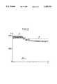
- FIG. 2shows an example of a curve of a measured impedance signal dependent on the blood volume in the heart for use in accordance with the principles of the present invention, given normal cardiac activity and given the presence of ventricular fibrillation.
- FIG. 1shows a block circuit diagram of a combined defibrillator 1 and heart pacemaker 2 constructed in accordance with the principles of the present invention. Both devices are capable of being arranged in a common, implantable housing or, as shown in FIG. 1, the devices can be respectively arranged in implantable housings 3 and 4.
- the heart pacemaker 2contains a stimulation pulse generator 5 having an out terminal 6 connected via an electrode line 7 to a stimulation electrode 10 arranged in the ventricle 8 of a heart 9.
- the second output terminal 11 of the stimulation pulse generator 5is connected to the housing 4 of the heart pacemaker 2, which serves as the return electrode for the stimulation electrode 10.
- the stimulation pulse generator 5is connected via a control line 12 to a pacemaker control 13, which initiates the output of stimulation pulses by the stimulation pulse generator 5 via the control line 12.
- a heartbeat detector 14, for detecting stimulated or natural cardiac activities,has a first input terminal 15 connected to the stimulation electrode 10, and has a second input terminal 16 connected to the housing 4 of the pacemaker 2.
- the heartbeat detector 14For controlling the function of the pacemaker 2 dependent on the detected electrical heart activities, the heartbeat detector 14 has an output 17 connected to the heart pacemaker control unit 13. An evaluation unit 18, which evaluates the detected electrical heart activities with respect to their frequency (repetition rate) is also connected to the output 17 of the heartbeat detector 14. The evaluation unit 18 has output connected to a first input 19 of an AND element 20, which has an output 21 connected to the pacemaker control unit 13.
- a voltmeter 22is also contained in the housing 4 of the pacemaker 2, and has a first input terminal 23 connected to the stimulation electrode 10 and a second input terminal 24 connected to the housing 4.
- the output of the voltmeter 22thus constitutes a transcardial measured impedance signal Z, derived from the aforementioned drop in the pulse amplitude.
- the measured impedance signal Zis supplied from the output 25 of the voltmeter 22 to an input of an evaluation stage 26.
- the evaluation stage 26includes a first detector 27 for detecting the drop in the level of the measured impedance signal Z below a predetermined threshold, and a second detector 28 wherein the speed with which the level of the measured impedance signal Z changes is monitored to determine whether the speed of the change upwardly transgresses a minimum speed.
- the two detector 27 and 28have respective outputs 29 and 30 connected through an AND element 31 to a second input 32 of the AND element 20.
- the pacemaker control unit 13is thus informed via the output 31 of the AND element 20 of the presence of ventricular fibrillation when the contraction repetition rate upwardly exceeds a prescribed value and when the level of the transcardiac impedance falls below a prescribed threshold with a minimum speed, for example, within a prescribed time window.
- the pacemaker control unit 13In response, the pacemaker control unit 13 generates a control signal to a control unit 34 of the defibrillator 1 via a control line 33. Alternatively, the pacemaker control unit 13 can communicate with the control unit 34 via a wireless signal transmission link. The control unit 34 thereupon activates a defibrillation pulse generator 35 to cause the delivery of a defibrillation pulse to the heart 9 via two defibrillation electrodes 36 and 37.
- FIG. 2An example of the curve of the measured impedance signal Z acquired between the stimulation electrode 10 and the housing 4 of the pacemaker 2 is shown in FIG. 2, given natural heart activity and given ventricular fibrillation thereafter.
- the measured impedance signal Z during the natural heart activityvaries dependent on the contractions of the heart muscle.
- the pumping activity of the heartchanges to a high-frequency, uncoordinated twitching of the myocardium, for which reason the frequency of the changes of the measured impedance signal Z increases, and the amplitude of the changes of the impedance signal Z drops.
- the general level of the measured impedance signal Zsuddenly drops given the appearance of ventricular fibrillation. This is attributed to the fact that the heart muscle is no longer pumping the blood given ventricular fibrillation, but is instead filling with blood. Given the apparatus shown in FIG. 1, this effect is utilized by detecting the sudden drop in the level of the measured impedance signal Z below the prescribed threshold S, this drop being a criterion for indicating the presence of ventricular fibrillation. It is sufficient for identifying the level of the measured impedance signal Z to acquire the measured values of the transcardial impedance with a low sampling frequency corresponding, for example, to the stimulation rate of the stimulation pulse generator 5 in FIG. 1.
- a running averageis formed over a few, for example, five, of the acquired measured values in order to suppress the influence of noise-like changes of the measured impedance signal Z on the detection of a downward transgression of the threshold S. It can also be provided, instead of this short-term averaging, to use a defined plurality of successive measured values which have downwardly transgressed the threshold S, in order to detect a drop in the level of the impedance signal Z below the threshold S.
- a long-term averageis additionally formed in the evaluation unit 26 from the measured values of measured impedance signal Z, and the threshold S is set to a value below the normal the average by a prescribed amount.
- low-energy electrical pulses generated by the defibrillation pulse generator 35can be used instead of the pacemaker pulse generated by the stimulation pulse generator 5 for measuring the transcardial impedance.
- the voltmeter 22is then connected to one or both of the defibrillation electrodes 36 and 37.
- an impedance measuring meanswhich is independent of both the pulse generators 5 and 35 can be used.
Landscapes
- Health & Medical Sciences (AREA)
- Cardiology (AREA)
- Life Sciences & Earth Sciences (AREA)
- Heart & Thoracic Surgery (AREA)
- Public Health (AREA)
- Engineering & Computer Science (AREA)
- Biomedical Technology (AREA)
- Veterinary Medicine (AREA)
- Animal Behavior & Ethology (AREA)
- General Health & Medical Sciences (AREA)
- Nuclear Medicine, Radiotherapy & Molecular Imaging (AREA)
- Radiology & Medical Imaging (AREA)
- Hematology (AREA)
- Biophysics (AREA)
- Physiology (AREA)
- Physics & Mathematics (AREA)
- Pathology (AREA)
- Medical Informatics (AREA)
- Molecular Biology (AREA)
- Surgery (AREA)
- Electrotherapy Devices (AREA)
- Measurement And Recording Of Electrical Phenomena And Electrical Characteristics Of The Living Body (AREA)
Abstract
Description
Claims (11)
Applications Claiming Priority (2)
| Application Number | Priority Date | Filing Date | Title |
|---|---|---|---|
| EP92114090 | 1992-08-18 | ||
| EP92114090AEP0583499B1 (en) | 1992-08-18 | 1992-08-18 | Method for detecting cardial ventricular fibrillation and means for detection and treating of cardial ventricular fibrillation |
Publications (1)
| Publication Number | Publication Date |
|---|---|
| US5385576Atrue US5385576A (en) | 1995-01-31 |
Family
ID=8209923
Family Applications (1)
| Application Number | Title | Priority Date | Filing Date |
|---|---|---|---|
| US08/101,727Expired - LifetimeUS5385576A (en) | 1992-08-18 | 1993-08-04 | Method for detecting ventricular fibrillation and apparatus for detecting and treating ventricular fibrillation |
Country Status (4)
| Country | Link |
|---|---|
| US (1) | US5385576A (en) |
| EP (1) | EP0583499B1 (en) |
| JP (1) | JPH06154186A (en) |
| DE (1) | DE59205611D1 (en) |
Cited By (10)
| Publication number | Priority date | Publication date | Assignee | Title |
|---|---|---|---|---|
| US5503157A (en)* | 1995-03-17 | 1996-04-02 | Sramek; Bohumir | System for detection of electrical bioimpedance signals |
| US5649969A (en)* | 1996-06-20 | 1997-07-22 | Pacesetter Ab | Method and apparatus for calculating and monitoring the impedance of an implanted pacemaker lead from a surface ECG of a pacemaker pulse |
| US5662687A (en)* | 1992-09-16 | 1997-09-02 | Pacesetter Ab | Implantable heart defibrillator |
| US5782879A (en)* | 1995-06-02 | 1998-07-21 | Sulzer Intermedics Inc. | Apparatus and method for discriminating flow of blood in a cardiovascular system |
| US5800467A (en)* | 1995-12-15 | 1998-09-01 | Pacesetter, Inc. | Cardio-synchronous impedance measurement system for an implantable stimulation device |
| WO2001060451A1 (en)* | 2000-02-17 | 2001-08-23 | BIOTRONIK MESS- UND THERAPIEGERäTE GMBH & CO. INGENIEURBüRO BERLIN | Device for detecting tachycardiac rhythm disturbances |
| US20080097539A1 (en)* | 2006-10-19 | 2008-04-24 | Andres Belalcazar | Method and apparatus for detecting fibrillation using cardiac local impedance |
| US20100114204A1 (en)* | 2008-10-31 | 2010-05-06 | Medtronic, Inc. | Interdevice impedance |
| US7840267B2 (en) | 2007-03-23 | 2010-11-23 | Cardiac Pacemakers, Inc. | Closed-loop resynchronization therapy for mechanical dyssynchrony |
| US7899531B1 (en)* | 2006-08-22 | 2011-03-01 | Pacesetter, Inc. | Neural sensing for atrial fibrillation |
Families Citing this family (5)
| Publication number | Priority date | Publication date | Assignee | Title |
|---|---|---|---|---|
| US5607455A (en)* | 1995-05-25 | 1997-03-04 | Intermedics, Inc. | Method and apparatus for automatic shock electrode enabling |
| US7986994B2 (en)* | 2002-12-04 | 2011-07-26 | Medtronic, Inc. | Method and apparatus for detecting change in intrathoracic electrical impedance |
| DE102005042923A1 (en)* | 2005-09-08 | 2007-03-22 | Biotronik Crm Patent Ag | Device for determining cardiac function parameters |
| DE102005047320A1 (en) | 2005-09-30 | 2007-04-05 | Biotronik Crm Patent Ag | Detector for atrial flicker and flutter |
| FR3103697B1 (en)* | 2019-12-03 | 2024-02-16 | Sorin Crm Sas | System for carrying out a cardiographic impedance measurement |
Citations (5)
| Publication number | Priority date | Publication date | Assignee | Title |
|---|---|---|---|---|
| EP0009255A1 (en)* | 1978-09-21 | 1980-04-02 | Purdue Research Foundation | An automatic cardiac ventricular defibrillator |
| GB2070282A (en)* | 1980-02-11 | 1981-09-03 | Mirowski M | Maximizing stroke volume artrioventricular pacing using implanted cardioverter/pacer |
| US4674518A (en)* | 1985-09-06 | 1987-06-23 | Cardiac Pacemakers, Inc. | Method and apparatus for measuring ventricular volume |
| US4697591A (en)* | 1986-06-16 | 1987-10-06 | Siemens Aktiengesellschaft | Cardiac pacer for pacing a human heart and pacing method |
| US5058583A (en)* | 1990-07-13 | 1991-10-22 | Geddes Leslie A | Multiple monopolar system and method of measuring stroke volume of the heart |
- 1992
- 1992-08-18EPEP92114090Apatent/EP0583499B1/ennot_activeExpired - Lifetime
- 1992-08-18DEDE59205611Tpatent/DE59205611D1/ennot_activeExpired - Fee Related
- 1993
- 1993-08-04USUS08/101,727patent/US5385576A/ennot_activeExpired - Lifetime
- 1993-08-18JPJP5203984Apatent/JPH06154186A/enactivePending
Patent Citations (6)
| Publication number | Priority date | Publication date | Assignee | Title |
|---|---|---|---|---|
| EP0009255A1 (en)* | 1978-09-21 | 1980-04-02 | Purdue Research Foundation | An automatic cardiac ventricular defibrillator |
| EP0074126A2 (en)* | 1978-09-21 | 1983-03-16 | Purdue Research Foundation | A method of cardiac ventricular defibrillation |
| GB2070282A (en)* | 1980-02-11 | 1981-09-03 | Mirowski M | Maximizing stroke volume artrioventricular pacing using implanted cardioverter/pacer |
| US4674518A (en)* | 1985-09-06 | 1987-06-23 | Cardiac Pacemakers, Inc. | Method and apparatus for measuring ventricular volume |
| US4697591A (en)* | 1986-06-16 | 1987-10-06 | Siemens Aktiengesellschaft | Cardiac pacer for pacing a human heart and pacing method |
| US5058583A (en)* | 1990-07-13 | 1991-10-22 | Geddes Leslie A | Multiple monopolar system and method of measuring stroke volume of the heart |
Cited By (17)
| Publication number | Priority date | Publication date | Assignee | Title |
|---|---|---|---|---|
| US5662687A (en)* | 1992-09-16 | 1997-09-02 | Pacesetter Ab | Implantable heart defibrillator |
| US5503157A (en)* | 1995-03-17 | 1996-04-02 | Sramek; Bohumir | System for detection of electrical bioimpedance signals |
| US5529072A (en)* | 1995-03-17 | 1996-06-25 | Sramek; Bohumir | System for detection of electrical bioimpedance signals |
| WO1996029003A1 (en)* | 1995-03-17 | 1996-09-26 | Bohumir Sramek | System for detection of electrical bioimpedance signals |
| US5782879A (en)* | 1995-06-02 | 1998-07-21 | Sulzer Intermedics Inc. | Apparatus and method for discriminating flow of blood in a cardiovascular system |
| US5800467A (en)* | 1995-12-15 | 1998-09-01 | Pacesetter, Inc. | Cardio-synchronous impedance measurement system for an implantable stimulation device |
| US5649969A (en)* | 1996-06-20 | 1997-07-22 | Pacesetter Ab | Method and apparatus for calculating and monitoring the impedance of an implanted pacemaker lead from a surface ECG of a pacemaker pulse |
| US20030105494A1 (en)* | 2000-02-17 | 2003-06-05 | Kaye Gerry C. | Device for detecting tachycardiac rhythm disturbances |
| WO2001060451A1 (en)* | 2000-02-17 | 2001-08-23 | BIOTRONIK MESS- UND THERAPIEGERäTE GMBH & CO. INGENIEURBüRO BERLIN | Device for detecting tachycardiac rhythm disturbances |
| US6961614B2 (en) | 2000-02-17 | 2005-11-01 | Kaye Gerry C | Device for detecting tachycardiac rhythm disturbances |
| US7899531B1 (en)* | 2006-08-22 | 2011-03-01 | Pacesetter, Inc. | Neural sensing for atrial fibrillation |
| US20080097539A1 (en)* | 2006-10-19 | 2008-04-24 | Andres Belalcazar | Method and apparatus for detecting fibrillation using cardiac local impedance |
| US7890163B2 (en)* | 2006-10-19 | 2011-02-15 | Cardiac Pacemakers, Inc. | Method and apparatus for detecting fibrillation using cardiac local impedance |
| US20110077540A1 (en)* | 2006-10-19 | 2011-03-31 | Andres Belalcazar | Method and apparatus for detecting fibrillation using cardiac local impedance |
| US7840267B2 (en) | 2007-03-23 | 2010-11-23 | Cardiac Pacemakers, Inc. | Closed-loop resynchronization therapy for mechanical dyssynchrony |
| US20100114204A1 (en)* | 2008-10-31 | 2010-05-06 | Medtronic, Inc. | Interdevice impedance |
| US9289613B2 (en)* | 2008-10-31 | 2016-03-22 | Medtronic, Inc. | Interdevice impedance |
Also Published As
| Publication number | Publication date |
|---|---|
| EP0583499A1 (en) | 1994-02-23 |
| DE59205611D1 (en) | 1996-04-11 |
| JPH06154186A (en) | 1994-06-03 |
| EP0583499B1 (en) | 1996-03-06 |
Similar Documents
| Publication | Publication Date | Title |
|---|---|---|
| JP3548177B2 (en) | Waveform discriminator for heart stimulator | |
| US4291699A (en) | Method of and apparatus for automatically detecting and treating ventricular fibrillation | |
| US5741311A (en) | Implantable medical device system with method for determining lead condition | |
| US5571143A (en) | Heart Stimulator | |
| US5385576A (en) | Method for detecting ventricular fibrillation and apparatus for detecting and treating ventricular fibrillation | |
| US7233825B2 (en) | Impedance measurement in implanted device | |
| US5522855A (en) | Implantable cardiac stimulator | |
| US4865036A (en) | Antitachyarrythmia pacemaker using pre-ejection period to distinguish physiologic from pathologic tachycardia | |
| US7894886B2 (en) | Method and apparatus for discriminating cardiac signals in a medical device based on wavelet decomposition analysis | |
| US5431687A (en) | Impedance timed defibrillation system | |
| US6238419B1 (en) | Heart stimulating device having fusion and pseudofusion heartbeat detection capability | |
| EP0882469B1 (en) | Implantable heart stimulator | |
| US5817134A (en) | Apparatus and method for detecting atrial fibrillation by morphological analysis | |
| US8394029B2 (en) | Night respiration rate for heart failure monitoring | |
| JP2001505093A (en) | Cardioversion / defibrillation lead lead impedance measurement system | |
| US5165404A (en) | Biological tissue stimulation device with control means for determining stimulation sensitivity calculation timing | |
| US5431172A (en) | Method for detecting tachyarrhythmia of a heart by measuring patient activity and partial pressure of blood oxygen | |
| AU614118B2 (en) | Configuration programming of an implantable pacemaker | |
| US5601614A (en) | Method and device for determining whether electrical signals in a heart are caused by an atrial depolarization | |
| US6078835A (en) | Pacemaker wherein emission of stimulation pulses is controlled dependent on stretching of the ventricular wall | |
| US7400924B2 (en) | System and method for capture management | |
| US6954671B1 (en) | Implantable heart stimulator or which identifies the origin of heart signals | |
| US6944500B1 (en) | Method and circuit for monitoring an oscillator in a medical implant | |
| US20090312812A1 (en) | Cardiac stimulator for treatment of tachycardiac arrhythmias of the heart | |
| US20090264945A1 (en) | Cardiac stimulator with stimulation success monitoring |
Legal Events
| Date | Code | Title | Description |
|---|---|---|---|
| AS | Assignment | Owner name:SIEMENS AKTIENGESELLSCHAFT, GERMANY Free format text:ASSIGNMENT OF ASSIGNORS INTEREST;ASSIGNORS:NOREN, KJELL;HAGEL, PIA;HOEGNELID, KURT;REEL/FRAME:006709/0761 Effective date:19930923 | |
| AS | Assignment | Owner name:PACESETTER AB, SWEDEN Free format text:ASSIGNMENT OF ASSIGNORS INTEREST;ASSIGNOR:SIEMENS AKTIENGESELLSCHAFT;REEL/FRAME:007308/0024 Effective date:19940922 | |
| STCF | Information on status: patent grant | Free format text:PATENTED CASE | |
| FEPP | Fee payment procedure | Free format text:PAYOR NUMBER ASSIGNED (ORIGINAL EVENT CODE: ASPN); ENTITY STATUS OF PATENT OWNER: LARGE ENTITY | |
| FPAY | Fee payment | Year of fee payment:4 | |
| FEPP | Fee payment procedure | Free format text:PAYER NUMBER DE-ASSIGNED (ORIGINAL EVENT CODE: RMPN); ENTITY STATUS OF PATENT OWNER: LARGE ENTITY Free format text:PAYOR NUMBER ASSIGNED (ORIGINAL EVENT CODE: ASPN); ENTITY STATUS OF PATENT OWNER: LARGE ENTITY | |
| FPAY | Fee payment | Year of fee payment:8 | |
| FPAY | Fee payment | Year of fee payment:12 |