US5385081A - Fluid storage tank employing a shear seal - Google Patents
Fluid storage tank employing a shear sealDownload PDFInfo
- Publication number
- US5385081A US5385081AUS08/118,952US11895293AUS5385081AUS 5385081 AUS5385081 AUS 5385081AUS 11895293 AUS11895293 AUS 11895293AUS 5385081 AUS5385081 AUS 5385081A
- Authority
- US
- United States
- Prior art keywords
- piston
- shear seal
- seal member
- shear
- seal
- Prior art date
- Legal status (The legal status is an assumption and is not a legal conclusion. Google has not performed a legal analysis and makes no representation as to the accuracy of the status listed.)
- Expired - Lifetime
Links
- 238000003860storageMethods0.000titleclaimsabstractdescription81
- 239000012530fluidSubstances0.000titleclaimsabstractdescription54
- 241000680172PlatytroctidaeSpecies0.000claims1
- 230000003068static effectEffects0.000abstractdescription3
- 239000003380propellantSubstances0.000description21
- 239000007788liquidSubstances0.000description16
- 239000000463materialSubstances0.000description8
- 239000007789gasSubstances0.000description6
- 230000000712assemblyEffects0.000description5
- 238000000429assemblyMethods0.000description5
- 239000000446fuelSubstances0.000description5
- 239000000203mixtureSubstances0.000description5
- 239000007787solidSubstances0.000description4
- 239000000725suspensionSubstances0.000description4
- 230000009972noncorrosive effectEffects0.000description3
- 239000004809TeflonSubstances0.000description2
- 229920006362Teflon®Polymers0.000description2
- 229910052782aluminiumInorganic materials0.000description2
- XAGFODPZIPBFFR-UHFFFAOYSA-NaluminiumChemical compound[Al]XAGFODPZIPBFFR-UHFFFAOYSA-N0.000description2
- 229910052751metalInorganic materials0.000description2
- 239000002184metalSubstances0.000description2
- 238000003466weldingMethods0.000description2
- 229920000181Ethylene propylene rubberPolymers0.000description1
- 235000015842HesperisNutrition0.000description1
- 235000012633Iberis amaraNutrition0.000description1
- 230000001133accelerationEffects0.000description1
- 230000004913activationEffects0.000description1
- 239000000853adhesiveSubstances0.000description1
- 230000001070adhesive effectEffects0.000description1
- 230000002411adverseEffects0.000description1
- 230000015572biosynthetic processEffects0.000description1
- 239000003518causticsSubstances0.000description1
- 230000007423decreaseEffects0.000description1
- 229920001971elastomerPolymers0.000description1
- 238000011156evaluationMethods0.000description1
- -1for examplePolymers0.000description1
- 238000007689inspectionMethods0.000description1
- 230000007257malfunctionEffects0.000description1
- 238000004519manufacturing processMethods0.000description1
- 238000000034methodMethods0.000description1
- 230000002028prematureEffects0.000description1
- 238000003825pressingMethods0.000description1
- 230000002035prolonged effectEffects0.000description1
- 238000007789sealingMethods0.000description1
- 229910001220stainless steelInorganic materials0.000description1
- 239000010935stainless steelSubstances0.000description1
- 238000006467substitution reactionMethods0.000description1
- WFKWXMTUELFFGS-UHFFFAOYSA-NtungstenChemical compound[W]WFKWXMTUELFFGS-UHFFFAOYSA-N0.000description1
- 229910052721tungstenInorganic materials0.000description1
- 239000010937tungstenSubstances0.000description1
Images


Classifications
- F—MECHANICAL ENGINEERING; LIGHTING; HEATING; WEAPONS; BLASTING
- F02—COMBUSTION ENGINES; HOT-GAS OR COMBUSTION-PRODUCT ENGINE PLANTS
- F02K—JET-PROPULSION PLANTS
- F02K9/00—Rocket-engine plants, i.e. plants carrying both fuel and oxidant therefor; Control thereof
- F02K9/42—Rocket-engine plants, i.e. plants carrying both fuel and oxidant therefor; Control thereof using liquid or gaseous propellants
- F02K9/60—Constructional parts; Details not otherwise provided for
- F02K9/605—Reservoirs
- F—MECHANICAL ENGINEERING; LIGHTING; HEATING; WEAPONS; BLASTING
- F16—ENGINEERING ELEMENTS AND UNITS; GENERAL MEASURES FOR PRODUCING AND MAINTAINING EFFECTIVE FUNCTIONING OF MACHINES OR INSTALLATIONS; THERMAL INSULATION IN GENERAL
- F16J—PISTONS; CYLINDERS; SEALINGS
- F16J15/00—Sealings
- F16J15/002—Sealings comprising at least two sealings in succession
- F16J15/008—Sealings comprising at least two sealings in succession with provision to put out of action at least one sealing; One sealing sealing only on standstill; Emergency or servicing sealings
- Y—GENERAL TAGGING OF NEW TECHNOLOGICAL DEVELOPMENTS; GENERAL TAGGING OF CROSS-SECTIONAL TECHNOLOGIES SPANNING OVER SEVERAL SECTIONS OF THE IPC; TECHNICAL SUBJECTS COVERED BY FORMER USPC CROSS-REFERENCE ART COLLECTIONS [XRACs] AND DIGESTS
- Y10—TECHNICAL SUBJECTS COVERED BY FORMER USPC
- Y10S—TECHNICAL SUBJECTS COVERED BY FORMER USPC CROSS-REFERENCE ART COLLECTIONS [XRACs] AND DIGESTS
- Y10S277/00—Seal for a joint or juncture
- Y10S277/905—T-Shaped or I-shaped ring member including seal on a side
- Y—GENERAL TAGGING OF NEW TECHNOLOGICAL DEVELOPMENTS; GENERAL TAGGING OF CROSS-SECTIONAL TECHNOLOGIES SPANNING OVER SEVERAL SECTIONS OF THE IPC; TECHNICAL SUBJECTS COVERED BY FORMER USPC CROSS-REFERENCE ART COLLECTIONS [XRACs] AND DIGESTS
- Y10—TECHNICAL SUBJECTS COVERED BY FORMER USPC
- Y10S—TECHNICAL SUBJECTS COVERED BY FORMER USPC CROSS-REFERENCE ART COLLECTIONS [XRACs] AND DIGESTS
- Y10S277/00—Seal for a joint or juncture
- Y10S277/917—Seal including frangible feature
Definitions
- the present inventionrelates to a fluid storage tank employing a shear seal to provide a substantially permanent leak proof static seal which can also easily be ruptured during system activation and yet still provide leak protection through use of a dynamic seal.
- the shear seal assembly of the present inventionis particularly useful as a rocket propellant storage tank.
- propellant fuelwhich is in the form of a liquid.
- This liquid propellantis typically stored in cylindrical storage tanks located within the body of the rocket or missile.
- a movable pistonis slidably mounted within the storage tank and is used to maintain the pressure of the liquid fuel in the storage chamber of the tank and to forcibly expel the liquid propellant from the tank through an appropriately located orifice under adverse acceleration environments when desired.
- Another fluida liquid, a gas, a gel, a suspension of solids, or a mixture of any one or more of these
- liquid propellantmay have to remain in its storage tank for many years before it is used, it is important that the liquid propellant remain within the storage tank and not seep past the piston.
- seepage of liquid propellant from the storage chamber of the rank into other portions of the rocketnot only results in propellant being lost and therefore reducing the range of the rocket, but may also result in a risk of premature ignition of the rocket or in damage to other parts of the rocket, as the propellant is typically extremely caustic.
- elastomeric sealsare often necessary to provide a dynamic seal for the piston as it moves within the storage tank.
- the materials from which such elastomeric seals are typically madegenerally degrade when exposed for a substantial length of time to the liquid propellant, thereby jeopardizing proper operation of the piston and the rocket.
- annular shear sealis mounted within the storage tank about the outer circumference of the piston so that it also contacts the inner surface of the wall of the storage tank.
- the annular shear sealis structurally sealed, such as by welding or other bonding means, along its central opening to the outside surface of the piston and along its outer circumference to the inner surface of the wall of the storage tank.
- the annular shear sealis disclosed as having a notch portion which is positioned on the shear seal between the point where the shear seal contacts the piston and the point where the shear seal contacts the storage tank wall. The shear seal and its two welds block leakage of the propellant before the rocket is activated.
- the disclosed shear seal designaids in preventing leakage of the propellant, the design requires at least two separate welds--one between the piston and the shear seal, and the other between the shear seal and the wall of the storage tank. Since the integrity of these two welds is critical to the proper operation of the storage tank, both of the welds must be inspected prior to final assembly of the tanks. The inspection of these two welds is a relatively time consuming and expensive process in view of the fact that they are located within the narrow confines of the storage rank and must be carried out by using X-ray photography.
- a shear sealtypically does not rupture uniformly along its the entire length of its notch due to variations of the notch profile, variations in the depth of the notch, variations in the thickness of the surrounding material, and variations in the metal comprising the shear seal itself. As a result, it may be expected that a notched shear seal as disclosed above will not break uniformly, at exactly the same position, and at the same moment along its entire length.
- the rupture point of a shear sealcannot be recessed too deeply into the wall of the storage tank because the elastomeric seals will have to pass over the recess in which the shear seal is mounted.
- jagged remnants of the shear sealmay be expected to remain, protrude, and tear or score the elastomeric annular seals on the piston.
- Such tears or scoring of the elastomeric sealsallow the propellant to leak around the piston when the piston is activated, thereby possibly causing the piston to malfunction. Remnants of the shear seal may also cause the piston to jam so that all of the propellant cannot be expelled.
- U.S. Pat. No. 3,545.343discloses a design which employs only one weld rather than two or more welds, however, this weld is very deep.
- a weldis applied from the outside of the storage tank and passes through the entire wall of the storage tank into a recess in the piston.
- the weldis disclosed to be thin enough so that it will rupture or shear when the piston begins to move.
- This designposes problems relating to the formation of a uniform deep weld, and to the evaluation of the integrity of the weld because of its depth.
- the designdoes not protect the elastomeric seals on the piston from getting torn or scored by remnants of the weld after the weld has ruptured.
- the present inventionrelates to a fluid storage tank which utilizes a shear seal which covers the entire piston head and that is attached to the storage chamber of the fluid storage tank by a single shallow weld.
- the shear sealwhich is preferably bonded to the surface of piston, is attached to the inner surface of the wall of the storage tank by a single weld which is located within a recess in the inner surface of the wall of the storage tank.
- the weldis fluid tight to prevent any leakage of the fluid from the fluid storage chamber to the elastomeric seals of the piston or to other portions of the storage tank beyond the piston.
- the shear sealhas a circumferential notch located proximate to its outer periphery.
- the head of the pistonin particular a circumferential shoulder on the outer periphery of the head of the piston, flattens against the wall of the fluid storage tank any protruding portions of the ruptured shear seal, including the jagged edge of the remnant of the shear seal that remains attached to the wall of the storage tank.
- the elastomeric sealsare not damaged when the piston slides and remnants of the ruptured shear seal will not cause the piston to jam while it slides within the tank.
- the present inventiontherefore requires only one shallow weld to seal off the fluid storage chamber of the fluid storage tank, thereby reducing the time of assembly of the storage tank, reducing the number of welds that must be inspected for integrity, and reducing the overall cost of manufacture.
- the present inventionalso uses the head of the piston to flatten any portions of the ruptured shear seal that may damage the elastomeric seals.
- the exit end of the storage tankhas the same shape as the head of the piston and the central portion of the shear seal.
- the head of the piston and the central portion of the shear sealare correspondingly also planar in shape
- the end of the storage tankis elliptical in shape
- the head of the piston and the central portion of the shear sealare correspondingly also in shape.
- a conduit tubepasses through the piston and shear seal.
- a conduit tubemay be used for transporting a fluid (a liquid, a gas, a gel, a suspension of solids, or a mixture of any one or more of these) to or from other fluid storage tanks, and/or for housing wires connected to remotely located sensors and/or controls.
- the conduit tubeis mounted within an aperture that passes through the piston and the shear seal.
- the shear sealcovers the entire piston head and is attached to the inner surface of the wall of the storage tank by a single weld which, as described above, is located within a recess in the inner surface of the wall of the storage tank.
- the shear sealhas the same circumferential notch located proximate to its outer periphery, and the piston has the same circumferential shoulder on the outer periphery of the piston to flatten any portions of the shear seal remaining when the piston is activated.
- the shear sealis also attached to the outer surface of the conduit tube in the same manner that the shear seal is attached to the inner surface of the storage tank.
- the shear sealis attached to the outer surface of the conduit tube by a single weld which is located within a recess in the outer surface of the conduit tube.
- This portion of the shear sealalso has a circumferential notch located proximate to the point where the shear seal is attached to the conduit tube.
- the end of the piston proximate to the aperture through which the conduit tube passeshas a circumferential shoulder on its inner periphery to flatten against the conduit tube any portions of the shear seal remaining when the piston is activated.
- the fluid storage tank of the present inventionis therefore particularly suited for storing liquid propellants in a rocket for long periods of time.
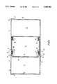
- FIG. 1is a schematic cross-sectional view of a propellant storage tank employing the shear seal of the present invention and wherein the end of the piston is planar in shape;
- FIG. 2is a detailed cross-sectional view of the portion of the shear seal of the present invention depicted within circle A in FIG. 1;
- FIG. 3is a schematic cross-sectional view of an alternative embodiment of the shear seal of the present invention where the end of the piston is elliptical in shape;
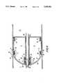
- FIG. 4is a schematic cross-sectional view of an alternative embodiment of the shear seal of the present invention wherein a conduit tube passes through the shear seal and the piston.
- the fluid storage tank 1 of the present inventionis generally cylindrical in shape, has an outer wall 2 and is made of a rigid material, such as, for example, aluminum or stainless steel, that is not corroded over a period of years by the fluid to be stored.
- the exit end 3 of storage tank 1is sealed by an exit endpiece 4 that is also made of rigid, non-corrosive material and, in the present embodiment, is substantially planar in shape.
- An outlet tube 6is mounted in exit endpiece 4.
- a piston 5is slidably mounted within storage tank 1.
- the central portion of the head 8 of piston 5is substantially planar in shape to match the shape of exit endpiece 4.
- piston 5has an overall cylindrical shape, the outer periphery of piston 5 proximate to piston head 8 is preferably tapered so that the diameter of piston 5 decreases slightly at piston head 8.
- inlet end 9 of storage tank 1is sealed by an inlet endpiece 10 which is made of a rigid, non-corrosive material and in which is mounted an inlet tube 11.
- Pressurant chamber 12is formed within storage tank 1 by piston 5 and inlet end piece 10.
- a shear seal 13is mounted within outer wall 2 of storage tank 1 between piston head 8 and exit endpiece 4 to form a fluid tight storage chamber 7.
- the fluid to be storedsuch as rocket propellant, is stored within fluid storage chamber 7.
- Shear seal 13is thin and is made of a rigid, non-corrosive, soft metal, such as aluminum and is attached by a circumferential weld 14 to the inner surface of outer wall 2 of storage tank 1.
- the attachment of shear seal 13is made in weld recess 16 of wall recess 15 formed along the entire inner circumference of outer wall 2.
- Tungsten Arc Gas WeldingTAGN
- shear seal 13is preferably attached to outer wall 2 by a weld, other means of attachment may be used, provided that the material comprising the attachment means does not corrode upon prolonged exposure to the fluid being stored, provided that it is impervious to the fluid, and provided that its structural integrity is greater than that of the shear seal 13 at its circumferential notch 22 (discussed below).
- the shape of the central portion of shear seal 13preferably matches the shape piston head 8 so that it fits snugly against piston head 8.
- piston head 8is substantially planar in shape, as shown in FIG. 1, the central portion of shear seal 13 is also substantially planar in shape.
- Shear seal 13is also preferably attached by an adhesive to piston head 8. Shear seal 13 thus provides a static seal to fluid storage chamber 7.
- annular seal assemblies 17are mounted within two circumferential seal recesses 18 in piston 5.
- One of the circumferential seal recesses 18is proximate to piston head 8 and the other is proximate to the end of piston 5 adjacent to pressurant chamber 12.
- Annular seal assemblies 17are annular in shape and tightly contact outer wall 2 of storage tank 1 to provide a tight seal between piston 5 and outer wall 2 and to prevent leakage of the fluid from storage chamber 7 past piston 5 after shear seal 13 has ruptured as discussed below.
- annular seal assemblies 17are shown as being mounted within recesses which prevent movement of the annular seal assemblies 17 when piston 5 moves, annular seal assemblies 17 may alternatively be merely mounted on the outer surface of piston 5.
- Annular seal assembly 17is preferably comprised of an annular T-seal 19 and two back-up rings 20.
- T-seal 19 and back-up rings 20are both comprised of a material which does not degrade quickly when exposed to the stored fluid.
- T-seal 19is made of material that remains resilient when exposed for a relatively short period of time to the fluid stored in storage chamber 7.
- T-seal 19is comprised of a high modular rubber such as, for example, ethylene propylene rubber, while back-up rings 20 are comprised of Teflon, most preferably virgin Teflon.
- Shear seal 13has a shoulder 21 proximate to its outer periphery into which is cut a circumferential notch 22 which encircles shear seal 13.
- Circumferential notch 22is preferably wedge shaped and is of a depth so that shear seal 13 will rupture along circumferential notch 22 as pressure is applied to piston 6, as described below.
- the outer periphery of shear seal 13 outside of shoulder 21fits within wall recess 15 which is of a depth so that when inserted into wall recess 15 shear seal 13 does not protrude beyond the inner surface of outer wall 2 of storage tank 1.
- wall recess 15is such that the outer periphery of shear seal 13 outside of shoulder 21 fits into wall recess 15 and so that when circumferential notch 22 ruptures any portions of shear seal 13 from its outer periphery to and slightly beyond circumferential notch 22 will also fit into seal recess 22.
- piston shoulder 23Around the circumference of piston head 8 is piston shoulder 23 which is positioned so that it is proximate to circumferential notch 22 of shear seal 13.
- Piston shoulder 23preferably has the shape of a blunt faced wedge so that its shortest portion is proximate circumferential notch 22 of shear seal 13 while the longest portion is proximate annular seal assembly 17.
- fluidis stored in storage chamber 7.
- a pressurant fluid(a liquid, a gas, a gel, a suspension of solids, or a mixture of any one or more of these) is introduced into storage tank 1 through inlet tube 10.
- pressurebuilds up in pressurant chamber 11 against piston 5 and thus against shear seal 13.
- the pressure exerted upon shear seal 13causes it to rupture along circumferential notch 22.
- the dynamic seal provided by annular seal assembly 17ensures that the stored fluid does not leak past piston 5 after shear seal 13 has ruptured and while piston 5 is moving. Piston 5 slides within storage tank 1 thereby increases the pressure in storage chamber 7, urging the stored fluid to be expelled from storage tank 1 through outlet tube 6.
- piston shoulder 23flattens any portions of shear seal 13 that extend out of wall recess 15, including the jagged edge of the remnant of the shear seal 13.
- all portions of shear seal 13 remaining attached to outer wall 2 by weld 14are removed from the path of piston 5, thereby preventing annular seal assembly 17 from being damaged.
- piston head 8 and the central portion of shear seal 13have the same planar shape as endpiece 4 of storage tank 1, when piston 5 has travelled the full length of storage chamber 7, substantially all of the propellant is expelled from storage chamber 7.
- FIG. 3shows an alternative embodiment of the present invention in which all of the elements are identical to those shown in FIGS. 1 and 2 except that piston head 8, the central portion of shear seal 13 and endpiece 4 of storage tank 1 are all generally elliptical in shape.
- FIG. 4shows an alternative embodiment of the present invention in which a conduit tube 24 passes through piston 5 and shear seal 13.
- Conduit tube 24is mounted within an aperture 25 that passes through piston 5 and shear seal 13.
- Conduit tube 24may be used for transporting a fluid (a liquid, a gas, a gel, a suspension of solids, or a mixture of any one or more of these)to or from other propellant storage tanks, and/or for housing wires connected to remotely located sensors and/or controls. All of the elements are identical to those shown in FIGS. 1, 2 and 3 except that additional sealing elements are present proximate to aperture 25 in piston 5. However, these elements are identical to those previously described above. In particular, the elements shown in FIG. 2 and within circle A in FIG.
- shear seal 13has two circumferential notches--one proximate to its outer periphery and another proximate to its central aperture through which conduit tube 24 passes.
- the head 8 of piston 5is tapered in two places and has two shoulders with which to flatten any portions of extruding shear seal after it has ruptured one proximate to the outer wall 2 of storage tank 1 and another proximate to the wall of conduit tube 24.
- the operation of the embodiment shown in FIG. 4is identical to that relating to the embodiment shown in FIG. 1 except that two circumferential notches of the shear seal rupture when piston 5 begins to move and two piston shoulders ensure that no remnants of the ruptured shear seal are protruding to damage the elastomeric seals.
- piston 5 and shear seal 13may have a cross-sectional shapes other than circular, such as, for example, elliptical, square or rectangular.
- piston head 8the central portion of shear seal 13 and endpiece 4 of storage tank 1 may be generally hemispherical or have an isotensoidal head profile.
- FIG. 4shows one conduit tube passing through the piston and the shear seal, more than one conduit tube may be used.
- the fluid storage tank of the present inventioncan be used in connection with various other fluids (liquids, gases or mixtures of both), corrosive or not.
Landscapes
- Engineering & Computer Science (AREA)
- General Engineering & Computer Science (AREA)
- Mechanical Engineering (AREA)
- Chemical & Material Sciences (AREA)
- Combustion & Propulsion (AREA)
- Filling Or Discharging Of Gas Storage Vessels (AREA)
Abstract
Description
The present invention relates to a fluid storage tank employing a shear seal to provide a substantially permanent leak proof static seal which can also easily be ruptured during system activation and yet still provide leak protection through use of a dynamic seal. The shear seal assembly of the present invention is particularly useful as a rocket propellant storage tank.
One of the main sources of fuel for the engines of rockets and missiles is propellant fuel which is in the form of a liquid. This liquid propellant is typically stored in cylindrical storage tanks located within the body of the rocket or missile. A movable piston is slidably mounted within the storage tank and is used to maintain the pressure of the liquid fuel in the storage chamber of the tank and to forcibly expel the liquid propellant from the tank through an appropriately located orifice under adverse acceleration environments when desired. Another fluid (a liquid, a gas, a gel, a suspension of solids, or a mixture of any one or more of these) is typically used as a pressurant to cause the piston to slide within the tank to pressurize the propellant or, alternatively, to expel the liquid fuel from the tank.
Since the liquid propellant may have to remain in its storage tank for many years before it is used, it is important that the liquid propellant remain within the storage tank and not seep past the piston. Such seepage of liquid propellant from the storage chamber of the rank into other portions of the rocket not only results in propellant being lost and therefore reducing the range of the rocket, but may also result in a risk of premature ignition of the rocket or in damage to other parts of the rocket, as the propellant is typically extremely caustic. Additionally, elastomeric seals are often necessary to provide a dynamic seal for the piston as it moves within the storage tank. However, the materials from which such elastomeric seals are typically made generally degrade when exposed for a substantial length of time to the liquid propellant, thereby jeopardizing proper operation of the piston and the rocket.
One solution to this problem is proposed in U.S. Pat. No. 5,042,365 wherein an annular shear seal is mounted within the storage tank about the outer circumference of the piston so that it also contacts the inner surface of the wall of the storage tank. The annular shear seal is structurally sealed, such as by welding or other bonding means, along its central opening to the outside surface of the piston and along its outer circumference to the inner surface of the wall of the storage tank. The annular shear seal is disclosed as having a notch portion which is positioned on the shear seal between the point where the shear seal contacts the piston and the point where the shear seal contacts the storage tank wall. The shear seal and its two welds block leakage of the propellant before the rocket is activated. When the rocket is to be activated, fluid pressure is applied to the piston, which causes the piston to exert an increasing force to the shear seal until a point when the shear seal ruptures along its notch. When the sear seal ruptures, the piston is free to slide and thereby expel the liquid fuel from the storage chamber of the tank. Although the disclosed shear seal design aids in preventing leakage of the propellant, the design requires at least two separate welds--one between the piston and the shear seal, and the other between the shear seal and the wall of the storage tank. Since the integrity of these two welds is critical to the proper operation of the storage tank, both of the welds must be inspected prior to final assembly of the tanks. The inspection of these two welds is a relatively time consuming and expensive process in view of the fact that they are located within the narrow confines of the storage rank and must be carried out by using X-ray photography.
Additionally, a shear seal typically does not rupture uniformly along its the entire length of its notch due to variations of the notch profile, variations in the depth of the notch, variations in the thickness of the surrounding material, and variations in the metal comprising the shear seal itself. As a result, it may be expected that a notched shear seal as disclosed above will not break uniformly, at exactly the same position, and at the same moment along its entire length. Furthermore, for the elastomeric seals to operate properly (i.e., provide a fluid tight seal while not impinging upon the freedom of movement of the piston), the rupture point of a shear seal cannot be recessed too deeply into the wall of the storage tank because the elastomeric seals will have to pass over the recess in which the shear seal is mounted. As a result, jagged remnants of the shear seal may be expected to remain, protrude, and tear or score the elastomeric annular seals on the piston. Such tears or scoring of the elastomeric seals allow the propellant to leak around the piston when the piston is activated, thereby possibly causing the piston to malfunction. Remnants of the shear seal may also cause the piston to jam so that all of the propellant cannot be expelled.
U.S. Pat. No. 3,545.343 discloses a design which employs only one weld rather than two or more welds, however, this weld is very deep. In this design, a weld is applied from the outside of the storage tank and passes through the entire wall of the storage tank into a recess in the piston. The weld is disclosed to be thin enough so that it will rupture or shear when the piston begins to move. This design poses problems relating to the formation of a uniform deep weld, and to the evaluation of the integrity of the weld because of its depth. In addition, the design does not protect the elastomeric seals on the piston from getting torn or scored by remnants of the weld after the weld has ruptured.
The present invention relates to a fluid storage tank which utilizes a shear seal which covers the entire piston head and that is attached to the storage chamber of the fluid storage tank by a single shallow weld. The shear seal, which is preferably bonded to the surface of piston, is attached to the inner surface of the wall of the storage tank by a single weld which is located within a recess in the inner surface of the wall of the storage tank. The weld is fluid tight to prevent any leakage of the fluid from the fluid storage chamber to the elastomeric seals of the piston or to other portions of the storage tank beyond the piston. The shear seal has a circumferential notch located proximate to its outer periphery. When the piston is pressurized, it is forced toward the exit end of the storage tank, thereby applying pressure to the stored fluid and to the shear seal. The shear seal ruptures along its circumferential notch, thereby allowing the piston to slide within the fluid storage tank. Elastomeric annular seals prevent the fluid from leaking between the piston and the wall of the storage tank while the piston is moving so that the fluid is forced out of the storage tank through an exit aperture located proximate to the exit end or the storage tank. The head of the piston, in particular a circumferential shoulder on the outer periphery of the head of the piston, flattens against the wall of the fluid storage tank any protruding portions of the ruptured shear seal, including the jagged edge of the remnant of the shear seal that remains attached to the wall of the storage tank. As a result the elastomeric seals are not damaged when the piston slides and remnants of the ruptured shear seal will not cause the piston to jam while it slides within the tank.
The present invention therefore requires only one shallow weld to seal off the fluid storage chamber of the fluid storage tank, thereby reducing the time of assembly of the storage tank, reducing the number of welds that must be inspected for integrity, and reducing the overall cost of manufacture. The present invention also uses the head of the piston to flatten any portions of the ruptured shear seal that may damage the elastomeric seals.
To ensure that the maximum amount of the stored fluid is expelled by the piston and shear seal, preferably the exit end of the storage tank has the same shape as the head of the piston and the central portion of the shear seal. Thus when the end of the storage tank is planar in shape, preferably the head of the piston and the central portion of the shear seal are correspondingly also planar in shape, and when the end of the storage tank is elliptical in shape, preferably the head of the piston and the central portion of the shear seal are correspondingly also in shape.
In an alternative embodiment of the present invention, a conduit tube passes through the piston and shear seal. Such a conduit tube may be used for transporting a fluid (a liquid, a gas, a gel, a suspension of solids, or a mixture of any one or more of these) to or from other fluid storage tanks, and/or for housing wires connected to remotely located sensors and/or controls. In this embodiment, the conduit tube is mounted within an aperture that passes through the piston and the shear seal. Again, the shear seal covers the entire piston head and is attached to the inner surface of the wall of the storage tank by a single weld which, as described above, is located within a recess in the inner surface of the wall of the storage tank. The shear seal has the same circumferential notch located proximate to its outer periphery, and the piston has the same circumferential shoulder on the outer periphery of the piston to flatten any portions of the shear seal remaining when the piston is activated. The shear seal is also attached to the outer surface of the conduit tube in the same manner that the shear seal is attached to the inner surface of the storage tank. Thus, the shear seal is attached to the outer surface of the conduit tube by a single weld which is located within a recess in the outer surface of the conduit tube. This portion of the shear seal also has a circumferential notch located proximate to the point where the shear seal is attached to the conduit tube. The end of the piston proximate to the aperture through which the conduit tube passes has a circumferential shoulder on its inner periphery to flatten against the conduit tube any portions of the shear seal remaining when the piston is activated.
The fluid storage tank of the present invention is therefore particularly suited for storing liquid propellants in a rocket for long periods of time.
Other objects and features of the present invention will become apparent from the following detailed description considered in conjunction with the accompanying drawings. It is to be understood, however, that the drawings are intended solely for purposes of illustration and not as a definition of the limits of the invention, for which reference should be made to the appended claims.
FIG. 1 is a schematic cross-sectional view of a propellant storage tank employing the shear seal of the present invention and wherein the end of the piston is planar in shape;
FIG. 2 is a detailed cross-sectional view of the portion of the shear seal of the present invention depicted within circle A in FIG. 1;
FIG. 3 is a schematic cross-sectional view of an alternative embodiment of the shear seal of the present invention where the end of the piston is elliptical in shape; and
FIG. 4 is a schematic cross-sectional view of an alternative embodiment of the shear seal of the present invention wherein a conduit tube passes through the shear seal and the piston.
Referring to FIGS. 1 and 2, the fluid storage tank 1 of the present invention is generally cylindrical in shape, has an outer wall 2 and is made of a rigid material, such as, for example, aluminum or stainless steel, that is not corroded over a period of years by the fluid to be stored. The exit end 3 of storage tank 1 is sealed by an exit endpiece 4 that is also made of rigid, non-corrosive material and, in the present embodiment, is substantially planar in shape. An outlet tube 6 is mounted in exit endpiece 4. Apiston 5 is slidably mounted within storage tank 1. In the present embodiment, the central portion of the head 8 ofpiston 5 is substantially planar in shape to match the shape of exit endpiece 4. Althoughpiston 5 has an overall cylindrical shape, the outer periphery ofpiston 5 proximate to piston head 8 is preferably tapered so that the diameter ofpiston 5 decreases slightly at piston head 8.
The inlet end 9 of storage tank 1 is sealed by aninlet endpiece 10 which is made of a rigid, non-corrosive material and in which is mounted an inlet tube 11. Pressurant chamber 12 is formed within storage tank 1 bypiston 5 andinlet end piece 10.
Ashear seal 13 is mounted within outer wall 2 of storage tank 1 between piston head 8 and exit endpiece 4 to form a fluidtight storage chamber 7. The fluid to be stored, such as rocket propellant, is stored withinfluid storage chamber 7.Shear seal 13 is thin and is made of a rigid, non-corrosive, soft metal, such as aluminum and is attached by acircumferential weld 14 to the inner surface of outer wall 2 of storage tank 1. The attachment ofshear seal 13 is made in weld recess 16 ofwall recess 15 formed along the entire inner circumference of outer wall 2.Circumferential weld 14, which may be applied by Tungsten Arc Gas Welding (TAGN), is of a size so that it does not protrude beyondwall recess 15. Althoughshear seal 13 is preferably attached to outer wall 2 by a weld, other means of attachment may be used, provided that the material comprising the attachment means does not corrode upon prolonged exposure to the fluid being stored, provided that it is impervious to the fluid, and provided that its structural integrity is greater than that of theshear seal 13 at its circumferential notch 22 (discussed below). The shape of the central portion ofshear seal 13 preferably matches the shape piston head 8 so that it fits snugly against piston head 8. Thus, when piston head 8 is substantially planar in shape, as shown in FIG. 1, the central portion ofshear seal 13 is also substantially planar in shape.Shear seal 13 is also preferably attached by an adhesive to piston head 8.Shear seal 13 thus provides a static seal tofluid storage chamber 7.
Twoannular seal assemblies 17 are mounted within two circumferential seal recesses 18 inpiston 5. One of the circumferential seal recesses 18 is proximate to piston head 8 and the other is proximate to the end ofpiston 5 adjacent to pressurant chamber 12.Annular seal assemblies 17 are annular in shape and tightly contact outer wall 2 of storage tank 1 to provide a tight seal betweenpiston 5 and outer wall 2 and to prevent leakage of the fluid fromstorage chamber 7past piston 5 aftershear seal 13 has ruptured as discussed below. Althoughannular seal assemblies 17 are shown as being mounted within recesses which prevent movement of theannular seal assemblies 17 whenpiston 5 moves,annular seal assemblies 17 may alternatively be merely mounted on the outer surface ofpiston 5.Annular seal assembly 17 is preferably comprised of an annular T-seal 19 and two back-up rings 20. T-seal 19 and back-up rings 20 are both comprised of a material which does not degrade quickly when exposed to the stored fluid. Additionally, T-seal 19 is made of material that remains resilient when exposed for a relatively short period of time to the fluid stored instorage chamber 7. Preferably, T-seal 19 is comprised of a high modular rubber such as, for example, ethylene propylene rubber, while back-up rings 20 are comprised of Teflon, most preferably virgin Teflon.
Since all of the elements described above appear around the circumference ofpiston 5, the portion shown of the shear seal of the present invention shown in FIG. 2 also appear identically but in a mirror image within the circle B in FIG. 1.
In operation, fluid is stored instorage chamber 7. A pressurant fluid (a liquid, a gas, a gel, a suspension of solids, or a mixture of any one or more of these) is introduced into storage tank 1 throughinlet tube 10. As a result, pressure builds up in pressurant chamber 11 againstpiston 5 and thus againstshear seal 13. The pressure exerted uponshear seal 13 causes it to rupture alongcircumferential notch 22. The dynamic seal provided byannular seal assembly 17 ensures that the stored fluid does not leakpast piston 5 aftershear seal 13 has ruptured and whilepiston 5 is moving.Piston 5 slides within storage tank 1 thereby increases the pressure instorage chamber 7, urging the stored fluid to be expelled from storage tank 1 through outlet tube 6. Aspiston 5 slides, the head 8 ofpiston 5, in particular,piston shoulder 23, flattens any portions ofshear seal 13 that extend out ofwall recess 15, including the jagged edge of the remnant of theshear seal 13. As a result of the length and depth ofwall recess 15, all portions ofshear seal 13 remaining attached to outer wall 2 byweld 14 are removed from the path ofpiston 5, thereby preventingannular seal assembly 17 from being damaged. Because piston head 8 and the central portion ofshear seal 13 have the same planar shape as endpiece 4 of storage tank 1, whenpiston 5 has travelled the full length ofstorage chamber 7, substantially all of the propellant is expelled fromstorage chamber 7.
FIG. 3 shows an alternative embodiment of the present invention in which all of the elements are identical to those shown in FIGS. 1 and 2 except that piston head 8, the central portion ofshear seal 13 and endpiece 4 of storage tank 1 are all generally elliptical in shape.
FIG. 4 shows an alternative embodiment of the present invention in which a conduit tube 24 passes throughpiston 5 andshear seal 13. Conduit tube 24 is mounted within anaperture 25 that passes throughpiston 5 andshear seal 13. Conduit tube 24 may be used for transporting a fluid (a liquid, a gas, a gel, a suspension of solids, or a mixture of any one or more of these)to or from other propellant storage tanks, and/or for housing wires connected to remotely located sensors and/or controls. All of the elements are identical to those shown in FIGS. 1, 2 and 3 except that additional sealing elements are present proximate toaperture 25 inpiston 5. However, these elements are identical to those previously described above. In particular, the elements shown in FIG. 2 and within circle A in FIG. 1 are identical to those within circle A' in FIG. 4 except thatwall recess 15 and weld recess 16 are present in the exterior wall of conduit tube 24. Thusshear seal 13 has two circumferential notches--one proximate to its outer periphery and another proximate to its central aperture through which conduit tube 24 passes. Similarly, the head 8 ofpiston 5 is tapered in two places and has two shoulders with which to flatten any portions of extruding shear seal after it has ruptured one proximate to the outer wall 2 of storage tank 1 and another proximate to the wall of conduit tube 24. The operation of the embodiment shown in FIG. 4 is identical to that relating to the embodiment shown in FIG. 1 except that two circumferential notches of the shear seal rupture whenpiston 5 begins to move and two piston shoulders ensure that no remnants of the ruptured shear seal are protruding to damage the elastomeric seals.
Thus, while there have been shown and described and pointed out fundamental novel features of the invention as applied to preferred embodiments thereof, it will be understood that various omissions and substitutions and changes in the form and details of the disclosed apparatus, and in its operation, may be made by those skilled in the art without departing from the spirit of the invention. It is the intention, therefore, to be limited only as indicated by the scope of the claims appended hereto.
For example, the shapes of various components may be changed. Storage tank 1, and thuspiston 5 andshear seal 13 may have a cross-sectional shapes other than circular, such as, for example, elliptical, square or rectangular. Additionally, piston head 8, the central portion ofshear seal 13 and endpiece 4 of storage tank 1 may be generally hemispherical or have an isotensoidal head profile. Although FIG. 4 shows one conduit tube passing through the piston and the shear seal, more than one conduit tube may be used.
Furthermore, although the invention has been described with reference to rocket propellant tanks, the fluid storage tank of the present invention can be used in connection with various other fluids (liquids, gases or mixtures of both), corrosive or not.
Claims (20)
1. A cylindrical tank for storing fluid comprising:
a cylindrical body (2) forming a wall of the tank, said cylindrical body having an inner surface in which is formed a circumferential wall recess (15);
an exit endpiece (4) fixedly attached to an exit end (3) of said cylindrical body (2) by a fluid tight seal;
an inlet endpiece (10) fixedly attached to an inlet end (10) of said cylindrical body (2) by a fluid tight seal;
a piston (5) slidably mounted within said cylindrical body (2) between said exit endpiece (4) and said inlet endpiece (10);
an annular seal (17) mounted on said piston (5) so that said annular seal (17) tightly contacts the inner surface of said cylindrical body (2) to provide a fluid tight seal between stud piston (5) and said cylindrical body (2); and
a shear seal member (13) mounted within said cylindrical body (2) between said piston (5) and said exit endpiece (4) and fixedly attached by a fluid tight seal to the inner surface of said cylindrical body (2) within said circumferential wall recess (15), said shear seal member (13) forming a fluid tight storage chamber (7) within said cylindrical body (2) between said shear seal member (13) and said exit endpiece (4) in which to store fluid, said shear seal member (13) having a circumferential notch (22) located proximate to an outer periphery of said shear seal member (13), the circumferential notch (22) reducing the thickness of said shear seal member (13) so that when said piston (5) is pressurized said shear seal member (13) ruptures along said circumferential notch (22).
2. The cylindrical tank of claim 1, wherein said piston (5) has a circumferential piston shoulder (23) positioned proximate to said shear seal member (13) between said shear seal member (13) and said annular seal (17), said piston shoulder (23) extending to approach the inner surface of said cylindrical body (2).
3. The cylindrical tank of claim 2, wherein said piston shoulder (23) is wedge shaped.
4. The cylindrical tank of claim 2, wherein an end of said piston (5) proximate to said shear seal member (13) is tapered.
5. The cylindrical tank of claim 1, wherein said shear seal (13) is fixedly attached to said piston (5).
6. The cylindrical tank of claim 1, wherein said shear seal member (13) is attached to said cylindrical body (2) by a weld.
7. The cylindrical tank of claim 1, wherein a central portion of said shear seal member (13) has the same shape as a central portion of a surface of said piston (5) adjacent to said shear seal member (13).
8. The cylindrical tank of claim 7, wherein the central portion of said shear seal member (13) and the central portion of said piston (5) are substantially planar.
9. The cylindrical tank of claim 7, wherein the central portion of said shear seal member (13) and the central portion of said piston (5) are substantially elliptical.
10. The cylindrical tank of claim 7, wherein the central portion of said shear seal member (13) and the central portion of said piston (5) have substantially isotensoidal head profiles.
11. The cylindrical tank of claim 1, wherein said shear seal member (13) has a circumferential shoulder (21) in which said circumferential notch is located.
12. The cylindrical tank of claim 1, further comprising:
a conduit tube (24) having an outer surface in which is formed a circumferential tube wall recess (15);
wherein said piston (5) has an aperture passing therethrough in which said conduit tube (24) is slidably mounted, and wherein said piston (5) further comprises an annular conduit seal (17) mounted on the piston so that said annular conduit seal (17) tightly contacts the outer surface of said conduit tube (24) to provide a fluid tight seal between said piston (5) and said conduit tube (24);
wherein said shear seal (13) has an aperture passing therethrough into which said conduit tube (24) is fixedly attached by a fluid tight seal to the outer surface of said conduit tube (24) within said circumferential tube wall recess (15) of said conduit tube (24), said shear seal member (13) having a conduit circumferential notch (22) located proximate to an inner periphery of the aperture in said shear seal member (13), the conduit circumferential notch (22) reducing the thickness of said shear seal member (13) so that when said piston (5) is pressurized said shear seal member (13) ruptures along said conduit circumferential notch (22); and further comprising:
an annular tube seal (17) mounted to said piston (5) within the aperture passing through said piston (5) so that said annular tube seal (17) tightly contacts the outer surface of said conduit tube (24) to provide a fluid tight seal between said piston (5) and said conduit tube (24).
13. The cylindrical tank of claim 12, wherein said piston (5) has a circumferential conduit shoulder (23) positioned proximate to said shear seal member (13) and between said shear seal member (13) and said annular tube seal (17), said piston shoulder (23) extending to approach the outer surface of said conduit tube (24).
14. The cylindrical tank of claim 13, wherein said piston shoulder (23) is wedge shaped.
15. The cylindrical tank of claim 13, wherein an end of said piston (5) proximate to said shear seal member (13) is tapered.
16. The cylindrical tank of claim 12, wherein said shear seal (13) is fixedly attached to said piston (5).
17. The cylindrical tank of claim 12, wherein said shear seal member (13) is attached to said cylindrical body (2) and said conduit tube (24) by welds.
18. The cylindrical tank of claim 12, wherein a central portion of said shear seal member (13) has the same shape as a central portion of a surface of said piston (5) adjacent to said shear seal member (13).
19. The cylindrical tank of claim 18, wherein the central portion of said shear seal member (13) and the central portion of said piston (5) are substantially elliptical.
20. The cylindrical tank of claim 12, wherein said shear seal member (13) has a circumferential shoulder (21) in which said circumferential notch is located and a circumferential tube shoulder (21) in which said conduit circumferential notch (22) is located.
Priority Applications (1)
| Application Number | Priority Date | Filing Date | Title |
|---|---|---|---|
| US08/118,952US5385081A (en) | 1993-09-09 | 1993-09-09 | Fluid storage tank employing a shear seal |
Applications Claiming Priority (1)
| Application Number | Priority Date | Filing Date | Title |
|---|---|---|---|
| US08/118,952US5385081A (en) | 1993-09-09 | 1993-09-09 | Fluid storage tank employing a shear seal |
Publications (1)
| Publication Number | Publication Date |
|---|---|
| US5385081Atrue US5385081A (en) | 1995-01-31 |
Family
ID=22381748
Family Applications (1)
| Application Number | Title | Priority Date | Filing Date |
|---|---|---|---|
| US08/118,952Expired - LifetimeUS5385081A (en) | 1993-09-09 | 1993-09-09 | Fluid storage tank employing a shear seal |
Country Status (1)
| Country | Link |
|---|---|
| US (1) | US5385081A (en) |
Cited By (30)
| Publication number | Priority date | Publication date | Assignee | Title |
|---|---|---|---|---|
| US5598762A (en)* | 1995-07-31 | 1997-02-04 | Arde Inc. | Fluid storage tank employing an isolation seal |
| US5921167A (en)* | 1997-08-26 | 1999-07-13 | Primex Aerospace Company | Hermetic shear seal for piston displacement fuel tank |
| US5931347A (en)* | 1997-05-23 | 1999-08-03 | Haubrich; Mark A. | Dispenser unit for viscous substances |
| US6027123A (en)* | 1997-09-10 | 2000-02-22 | Cbw Transport Services, Inc. | Tank piston with improved seal and wiper |
| US6138848A (en)* | 1999-03-11 | 2000-10-31 | Fermo; Philip J. | Baby bottle |
| US6325384B1 (en) | 1997-09-10 | 2001-12-04 | Transportation Leasing Corporation | Tank piston with improved seal and wiper |
| US6348124B1 (en)* | 1999-12-14 | 2002-02-19 | Applied Materials, Inc. | Delivery of polishing agents in a wafer processing system |
| US6511075B1 (en)* | 1999-04-01 | 2003-01-28 | Dichtungstechnik G. Bruss Gmbh & Co. | Elastomer seal between a piston and a cylinder or a shaft on an automatic transmission |
| US20030032964A1 (en)* | 2001-02-15 | 2003-02-13 | Neil Watkins | Vertebroplasty bone cement |
| US20040069813A1 (en)* | 2002-10-10 | 2004-04-15 | Gene Brisson | Piston and seal for a storage tank |
| US6796463B2 (en) | 2001-10-09 | 2004-09-28 | Stewart Boal, Jr. | Inflatable and collapsible apparatus for dispensing fluid from a fluid vessel |
| US20040193171A1 (en)* | 2003-03-31 | 2004-09-30 | Depuy Acromed, Inc. | Remotely-activated vertebroplasty injection device |
| US20060079905A1 (en)* | 2003-06-17 | 2006-04-13 | Disc-O-Tech Medical Technologies Ltd. | Methods, materials and apparatus for treating bone and other tissue |
| US20070027230A1 (en)* | 2004-03-21 | 2007-02-01 | Disc-O-Tech Medical Technologies Ltd. | Methods, materials, and apparatus for treating bone and other tissue |
| US20070032567A1 (en)* | 2003-06-17 | 2007-02-08 | Disc-O-Tech Medical | Bone Cement And Methods Of Use Thereof |
| US20080200915A1 (en)* | 2005-07-31 | 2008-08-21 | Disc-O-Tech Medical Technologies, Ltd. | Marked tools |
| US20080212405A1 (en)* | 2005-11-22 | 2008-09-04 | Disc-O-Tech Medical Technologies, Ltd. | Mixing Apparatus |
| WO2009002014A1 (en)* | 2007-06-28 | 2008-12-31 | Byung-Sue Ryu | Sealing apparatus for square piston used for compressing and feeding fluid |
| US20100326221A1 (en)* | 2007-06-25 | 2010-12-30 | Fiti Testing & Research Institute | Method and apparatus for measuring drying time of quick wet and dried fabrics |
| US20110283880A1 (en)* | 2010-05-19 | 2011-11-24 | Smc Kabushiki Kaisha | Fluid pressure apparatus |
| US20110285095A1 (en)* | 2010-05-19 | 2011-11-24 | Smc Kabushiki Kaisha | Fluid pressure apparatus |
| US8579908B2 (en) | 2003-09-26 | 2013-11-12 | DePuy Synthes Products, LLC. | Device for delivering viscous material |
| US8950929B2 (en) | 2006-10-19 | 2015-02-10 | DePuy Synthes Products, LLC | Fluid delivery system |
| US8992541B2 (en) | 2003-03-14 | 2015-03-31 | DePuy Synthes Products, LLC | Hydraulic device for the injection of bone cement in percutaneous vertebroplasty |
| US9067728B2 (en) | 2012-03-01 | 2015-06-30 | Clasen Quality Coatings, Inc. | Container including a magnetically operated scraper |
| US9194495B2 (en) | 2010-05-19 | 2015-11-24 | Smc Kabushiki Kaisha | Fluid pressure apparatus |
| US9642932B2 (en) | 2006-09-14 | 2017-05-09 | DePuy Synthes Products, Inc. | Bone cement and methods of use thereof |
| US9918767B2 (en) | 2005-08-01 | 2018-03-20 | DePuy Synthes Products, Inc. | Temperature control system |
| US10563763B1 (en) | 2017-03-31 | 2020-02-18 | Piston Tank Corporation | Tank piston with improved seal and cover |
| WO2023235743A1 (en)* | 2022-06-01 | 2023-12-07 | Shell Usa, Inc. | System for hydroprocessing a solid feedstock with piston feedstock feeder system having a t-shape annular piston sealing ring |
Citations (8)
| Publication number | Priority date | Publication date | Assignee | Title |
|---|---|---|---|---|
| US3130547A (en)* | 1962-09-27 | 1964-04-28 | Charles F Nash | Fluid control device |
| US3138001A (en)* | 1962-10-11 | 1964-06-23 | William I Berks | Device to eliminate shear slide in prepackaged liquid powerplants |
| US3368751A (en)* | 1966-04-18 | 1968-02-13 | Honeywell Inc | Control apparatus |
| US3545343A (en)* | 1968-04-15 | 1970-12-08 | United Aircraft Corp | Welded fluid seal |
| US3680310A (en)* | 1967-05-19 | 1972-08-01 | Us Navy | Starting device for monopropellant gas generator |
| US3923208A (en)* | 1974-07-19 | 1975-12-02 | Us Army | Fluid expulsion system having a tapered tank |
| US4538749A (en)* | 1981-07-13 | 1985-09-03 | Rockwell International Corporation | Non-circular rolling diaphragm liquid expulsion apparatus |
| US5042365A (en)* | 1983-08-15 | 1991-08-27 | Rockwell International Corporation | Annular preloaded seal for a sliding piston in cylindrical tank |
- 1993
- 1993-09-09USUS08/118,952patent/US5385081A/ennot_activeExpired - Lifetime
Patent Citations (8)
| Publication number | Priority date | Publication date | Assignee | Title |
|---|---|---|---|---|
| US3130547A (en)* | 1962-09-27 | 1964-04-28 | Charles F Nash | Fluid control device |
| US3138001A (en)* | 1962-10-11 | 1964-06-23 | William I Berks | Device to eliminate shear slide in prepackaged liquid powerplants |
| US3368751A (en)* | 1966-04-18 | 1968-02-13 | Honeywell Inc | Control apparatus |
| US3680310A (en)* | 1967-05-19 | 1972-08-01 | Us Navy | Starting device for monopropellant gas generator |
| US3545343A (en)* | 1968-04-15 | 1970-12-08 | United Aircraft Corp | Welded fluid seal |
| US3923208A (en)* | 1974-07-19 | 1975-12-02 | Us Army | Fluid expulsion system having a tapered tank |
| US4538749A (en)* | 1981-07-13 | 1985-09-03 | Rockwell International Corporation | Non-circular rolling diaphragm liquid expulsion apparatus |
| US5042365A (en)* | 1983-08-15 | 1991-08-27 | Rockwell International Corporation | Annular preloaded seal for a sliding piston in cylindrical tank |
Cited By (61)
| Publication number | Priority date | Publication date | Assignee | Title |
|---|---|---|---|---|
| US5598762A (en)* | 1995-07-31 | 1997-02-04 | Arde Inc. | Fluid storage tank employing an isolation seal |
| US5931347A (en)* | 1997-05-23 | 1999-08-03 | Haubrich; Mark A. | Dispenser unit for viscous substances |
| US5921167A (en)* | 1997-08-26 | 1999-07-13 | Primex Aerospace Company | Hermetic shear seal for piston displacement fuel tank |
| US6027123A (en)* | 1997-09-10 | 2000-02-22 | Cbw Transport Services, Inc. | Tank piston with improved seal and wiper |
| US6325384B1 (en) | 1997-09-10 | 2001-12-04 | Transportation Leasing Corporation | Tank piston with improved seal and wiper |
| US6138848A (en)* | 1999-03-11 | 2000-10-31 | Fermo; Philip J. | Baby bottle |
| US6511075B1 (en)* | 1999-04-01 | 2003-01-28 | Dichtungstechnik G. Bruss Gmbh & Co. | Elastomer seal between a piston and a cylinder or a shaft on an automatic transmission |
| US6348124B1 (en)* | 1999-12-14 | 2002-02-19 | Applied Materials, Inc. | Delivery of polishing agents in a wafer processing system |
| US7008433B2 (en) | 2001-02-15 | 2006-03-07 | Depuy Acromed, Inc. | Vertebroplasty injection device |
| US20030032964A1 (en)* | 2001-02-15 | 2003-02-13 | Neil Watkins | Vertebroplasty bone cement |
| US6796463B2 (en) | 2001-10-09 | 2004-09-28 | Stewart Boal, Jr. | Inflatable and collapsible apparatus for dispensing fluid from a fluid vessel |
| US6916025B2 (en) | 2002-10-10 | 2005-07-12 | Piston Technology, Llc | Piston and seal for a storage tank |
| US20040069813A1 (en)* | 2002-10-10 | 2004-04-15 | Gene Brisson | Piston and seal for a storage tank |
| US10799278B2 (en) | 2003-03-14 | 2020-10-13 | DePuy Synthes Products, Inc. | Hydraulic device for the injection of bone cement in percutaneous vertebroplasty |
| US9186194B2 (en) | 2003-03-14 | 2015-11-17 | DePuy Synthes Products, Inc. | Hydraulic device for the injection of bone cement in percutaneous vertebroplasty |
| US8992541B2 (en) | 2003-03-14 | 2015-03-31 | DePuy Synthes Products, LLC | Hydraulic device for the injection of bone cement in percutaneous vertebroplasty |
| US20040193171A1 (en)* | 2003-03-31 | 2004-09-30 | Depuy Acromed, Inc. | Remotely-activated vertebroplasty injection device |
| US20090270872A1 (en)* | 2003-03-31 | 2009-10-29 | Depuy Spine, Inc. | Remotely-activated vertebroplasty injection device |
| US10485597B2 (en) | 2003-03-31 | 2019-11-26 | DePuy Synthes Products, Inc. | Remotely-activated vertebroplasty injection device |
| US9839460B2 (en) | 2003-03-31 | 2017-12-12 | DePuy Synthes Products, Inc. | Remotely-activated vertebroplasty injection device |
| US20080039856A1 (en)* | 2003-03-31 | 2008-02-14 | Depuy Spine, Inc. | Remotely-activated vertebroplasty injection device |
| US8333773B2 (en) | 2003-03-31 | 2012-12-18 | Depuy Spine, Inc. | Remotely-activated vertebroplasty injection device |
| US8066713B2 (en) | 2003-03-31 | 2011-11-29 | Depuy Spine, Inc. | Remotely-activated vertebroplasty injection device |
| US8361078B2 (en) | 2003-06-17 | 2013-01-29 | Depuy Spine, Inc. | Methods, materials and apparatus for treating bone and other tissue |
| US8540722B2 (en) | 2003-06-17 | 2013-09-24 | DePuy Synthes Products, LLC | Methods, materials and apparatus for treating bone and other tissue |
| US20060079905A1 (en)* | 2003-06-17 | 2006-04-13 | Disc-O-Tech Medical Technologies Ltd. | Methods, materials and apparatus for treating bone and other tissue |
| US9504508B2 (en) | 2003-06-17 | 2016-11-29 | DePuy Synthes Products, Inc. | Methods, materials and apparatus for treating bone and other tissue |
| US20070032567A1 (en)* | 2003-06-17 | 2007-02-08 | Disc-O-Tech Medical | Bone Cement And Methods Of Use Thereof |
| US20090264942A1 (en)* | 2003-06-17 | 2009-10-22 | Depuy Spine, Inc. | Methods, Materials and Apparatus for Treating Bone and Other Tissue |
| US20090264892A1 (en)* | 2003-06-17 | 2009-10-22 | Depuy Spine, Inc. | Methods, Materials and Apparatus for Treating Bone or Other Tissue |
| US10039585B2 (en) | 2003-06-17 | 2018-08-07 | DePuy Synthes Products, Inc. | Methods, materials and apparatus for treating bone and other tissue |
| US8956368B2 (en) | 2003-06-17 | 2015-02-17 | DePuy Synthes Products, LLC | Methods, materials and apparatus for treating bone and other tissue |
| US10111697B2 (en) | 2003-09-26 | 2018-10-30 | DePuy Synthes Products, Inc. | Device for delivering viscous material |
| US8579908B2 (en) | 2003-09-26 | 2013-11-12 | DePuy Synthes Products, LLC. | Device for delivering viscous material |
| US20070027230A1 (en)* | 2004-03-21 | 2007-02-01 | Disc-O-Tech Medical Technologies Ltd. | Methods, materials, and apparatus for treating bone and other tissue |
| US8415407B2 (en) | 2004-03-21 | 2013-04-09 | Depuy Spine, Inc. | Methods, materials, and apparatus for treating bone and other tissue |
| US8809418B2 (en) | 2004-03-21 | 2014-08-19 | DePuy Synthes Products, LLC | Methods, materials and apparatus for treating bone and other tissue |
| US9750840B2 (en) | 2004-03-21 | 2017-09-05 | DePuy Synthes Products, Inc. | Methods, materials and apparatus for treating bone and other tissue |
| US20080200915A1 (en)* | 2005-07-31 | 2008-08-21 | Disc-O-Tech Medical Technologies, Ltd. | Marked tools |
| US9381024B2 (en) | 2005-07-31 | 2016-07-05 | DePuy Synthes Products, Inc. | Marked tools |
| US9918767B2 (en) | 2005-08-01 | 2018-03-20 | DePuy Synthes Products, Inc. | Temperature control system |
| US10631906B2 (en) | 2005-11-22 | 2020-04-28 | DePuy Synthes Products, Inc. | Apparatus for transferring a viscous material |
| US8360629B2 (en) | 2005-11-22 | 2013-01-29 | Depuy Spine, Inc. | Mixing apparatus having central and planetary mixing elements |
| US20080212405A1 (en)* | 2005-11-22 | 2008-09-04 | Disc-O-Tech Medical Technologies, Ltd. | Mixing Apparatus |
| US9259696B2 (en) | 2005-11-22 | 2016-02-16 | DePuy Synthes Products, Inc. | Mixing apparatus having central and planetary mixing elements |
| US10272174B2 (en) | 2006-09-14 | 2019-04-30 | DePuy Synthes Products, Inc. | Bone cement and methods of use thereof |
| US9642932B2 (en) | 2006-09-14 | 2017-05-09 | DePuy Synthes Products, Inc. | Bone cement and methods of use thereof |
| US8950929B2 (en) | 2006-10-19 | 2015-02-10 | DePuy Synthes Products, LLC | Fluid delivery system |
| US10494158B2 (en) | 2006-10-19 | 2019-12-03 | DePuy Synthes Products, Inc. | Fluid delivery system |
| US8495907B2 (en) | 2007-06-25 | 2013-07-30 | Fiti Testing & Research Institute | Method and apparatus for measuring drying time of quick wet and dried fabrics |
| US20100326221A1 (en)* | 2007-06-25 | 2010-12-30 | Fiti Testing & Research Institute | Method and apparatus for measuring drying time of quick wet and dried fabrics |
| US20100319530A1 (en)* | 2007-06-28 | 2010-12-23 | Byung Sue Ryu | Sealing apparatus for square piston used for compressing and feeding fluid |
| WO2009002014A1 (en)* | 2007-06-28 | 2008-12-31 | Byung-Sue Ryu | Sealing apparatus for square piston used for compressing and feeding fluid |
| US9194495B2 (en) | 2010-05-19 | 2015-11-24 | Smc Kabushiki Kaisha | Fluid pressure apparatus |
| US9127771B2 (en)* | 2010-05-19 | 2015-09-08 | Smc Kabushiki Kaisha | Fluid pressure apparatus |
| US8739684B2 (en)* | 2010-05-19 | 2014-06-03 | Smc Kabushiki Kaisha | Fluid pressure apparatus |
| US20110285095A1 (en)* | 2010-05-19 | 2011-11-24 | Smc Kabushiki Kaisha | Fluid pressure apparatus |
| US20110283880A1 (en)* | 2010-05-19 | 2011-11-24 | Smc Kabushiki Kaisha | Fluid pressure apparatus |
| US9067728B2 (en) | 2012-03-01 | 2015-06-30 | Clasen Quality Coatings, Inc. | Container including a magnetically operated scraper |
| US10563763B1 (en) | 2017-03-31 | 2020-02-18 | Piston Tank Corporation | Tank piston with improved seal and cover |
| WO2023235743A1 (en)* | 2022-06-01 | 2023-12-07 | Shell Usa, Inc. | System for hydroprocessing a solid feedstock with piston feedstock feeder system having a t-shape annular piston sealing ring |
Similar Documents
| Publication | Publication Date | Title |
|---|---|---|
| US5385081A (en) | Fluid storage tank employing a shear seal | |
| US3945539A (en) | Method and apparatus for expelling fluids | |
| US3097766A (en) | Pre-filled propellant tank for rockets | |
| US4219126A (en) | Safe cartridge for gas | |
| KR940014017A (en) | Liquefied gas generator for inflatable shock protection cushion to prevent occupant damage | |
| KR950013851A (en) | Apparatus for inflating air bags | |
| US3913604A (en) | Piston-actuated fluid discharge device | |
| US8297652B2 (en) | Gas generating system | |
| US4030644A (en) | Non-return safety valve assembly and pressure pack incorporating same | |
| US5598762A (en) | Fluid storage tank employing an isolation seal | |
| US3494370A (en) | Explosive valve | |
| US2954670A (en) | Method of propellant stowage, arming and initiation of propellant flow for a liquid fuel propulsion system in a liquid fuel rocket motor | |
| US3983892A (en) | Explosive valve | |
| US3397712A (en) | Valve having a rupturable seal assembly | |
| US3121310A (en) | Closure device | |
| EP0693303A2 (en) | Discharging fire and explosion suppressants | |
| US3780752A (en) | Explosively actuated valve | |
| US4413746A (en) | Pressurized-fluid cartridge and safety closure therefor | |
| US5921167A (en) | Hermetic shear seal for piston displacement fuel tank | |
| US2754656A (en) | Automatic valve | |
| US3435996A (en) | Positive expulsion device | |
| US20040007123A1 (en) | Hermetically sealed actuator | |
| US5042365A (en) | Annular preloaded seal for a sliding piston in cylindrical tank | |
| US6324832B1 (en) | Ampoule with starting fuel for igniting LRE propellant components | |
| US2958185A (en) | Pressure responsive safety device for jet propulsion motors |
Legal Events
| Date | Code | Title | Description |
|---|---|---|---|
| AS | Assignment | Owner name:ARDE INC., NEW JERSEY Free format text:ASSIGNMENT OF ASSIGNORS INTEREST;ASSIGNOR:SNEDDON, KIRK;REEL/FRAME:006810/0361 Effective date:19931004 | |
| STCF | Information on status: patent grant | Free format text:PATENTED CASE | |
| FPAY | Fee payment | Year of fee payment:4 | |
| FPAY | Fee payment | Year of fee payment:8 | |
| FPAY | Fee payment | Year of fee payment:12 | |
| AS | Assignment | Owner name:WELLS FARGO BANK, NATIONAL ASSOCIATION, NORTH CARO Free format text:SECURITY AGREEMENT;ASSIGNOR:ARDE, INC.;REEL/FRAME:030628/0871 Effective date:20130614 | |
| AS | Assignment | Owner name:U.S. BANK NATIONAL ASSOCIATION, CALIFORNIA Free format text:SECURITY AGREEMENT;ASSIGNOR:ARDE, INC.;REEL/FRAME:030666/0127 Effective date:20130614 | |
| AS | Assignment | Owner name:ARDE, INC., NEW JERSEY Free format text:RELEASE BY SECURED PARTY;ASSIGNOR:U.S. BANK NATIONAL ASSOCIATION;REEL/FRAME:039356/0118 Effective date:20160715 |