US5384849A - Apparatus and method for encoding/decoding data including the suppression of blocking artifacts - Google Patents
Apparatus and method for encoding/decoding data including the suppression of blocking artifactsDownload PDFInfo
- Publication number
- US5384849A US5384849AUS08/062,599US6259993AUS5384849AUS 5384849 AUS5384849 AUS 5384849AUS 6259993 AUS6259993 AUS 6259993AUS 5384849 AUS5384849 AUS 5384849A
- Authority
- US
- United States
- Prior art keywords
- data
- post
- frame data
- processing parameter
- degree
- Prior art date
- Legal status (The legal status is an assumption and is not a legal conclusion. Google has not performed a legal analysis and makes no representation as to the accuracy of the status listed.)
- Expired - Lifetime
Links
Images


Classifications
- H—ELECTRICITY
- H04—ELECTRIC COMMUNICATION TECHNIQUE
- H04N—PICTORIAL COMMUNICATION, e.g. TELEVISION
- H04N19/00—Methods or arrangements for coding, decoding, compressing or decompressing digital video signals
- H04N19/85—Methods or arrangements for coding, decoding, compressing or decompressing digital video signals using pre-processing or post-processing specially adapted for video compression
- H04N19/86—Methods or arrangements for coding, decoding, compressing or decompressing digital video signals using pre-processing or post-processing specially adapted for video compression involving reduction of coding artifacts, e.g. of blockiness
- H—ELECTRICITY
- H04—ELECTRIC COMMUNICATION TECHNIQUE
- H04N—PICTORIAL COMMUNICATION, e.g. TELEVISION
- H04N7/00—Television systems
- H04N7/12—Systems in which the television signal is transmitted via one channel or a plurality of parallel channels, the bandwidth of each channel being less than the bandwidth of the television signal
- H—ELECTRICITY
- H04—ELECTRIC COMMUNICATION TECHNIQUE
- H04N—PICTORIAL COMMUNICATION, e.g. TELEVISION
- H04N19/00—Methods or arrangements for coding, decoding, compressing or decompressing digital video signals
- H04N19/10—Methods or arrangements for coding, decoding, compressing or decompressing digital video signals using adaptive coding
- H04N19/102—Methods or arrangements for coding, decoding, compressing or decompressing digital video signals using adaptive coding characterised by the element, parameter or selection affected or controlled by the adaptive coding
- H04N19/117—Filters, e.g. for pre-processing or post-processing
- H—ELECTRICITY
- H04—ELECTRIC COMMUNICATION TECHNIQUE
- H04N—PICTORIAL COMMUNICATION, e.g. TELEVISION
- H04N19/00—Methods or arrangements for coding, decoding, compressing or decompressing digital video signals
- H04N19/10—Methods or arrangements for coding, decoding, compressing or decompressing digital video signals using adaptive coding
- H04N19/134—Methods or arrangements for coding, decoding, compressing or decompressing digital video signals using adaptive coding characterised by the element, parameter or criterion affecting or controlling the adaptive coding
- H04N19/154—Measured or subjectively estimated visual quality after decoding, e.g. measurement of distortion
- H—ELECTRICITY
- H04—ELECTRIC COMMUNICATION TECHNIQUE
- H04N—PICTORIAL COMMUNICATION, e.g. TELEVISION
- H04N19/00—Methods or arrangements for coding, decoding, compressing or decompressing digital video signals
- H04N19/10—Methods or arrangements for coding, decoding, compressing or decompressing digital video signals using adaptive coding
- H04N19/169—Methods or arrangements for coding, decoding, compressing or decompressing digital video signals using adaptive coding characterised by the coding unit, i.e. the structural portion or semantic portion of the video signal being the object or the subject of the adaptive coding
- H04N19/17—Methods or arrangements for coding, decoding, compressing or decompressing digital video signals using adaptive coding characterised by the coding unit, i.e. the structural portion or semantic portion of the video signal being the object or the subject of the adaptive coding the unit being an image region, e.g. an object
- H04N19/172—Methods or arrangements for coding, decoding, compressing or decompressing digital video signals using adaptive coding characterised by the coding unit, i.e. the structural portion or semantic portion of the video signal being the object or the subject of the adaptive coding the unit being an image region, e.g. an object the region being a picture, frame or field
- H—ELECTRICITY
- H04—ELECTRIC COMMUNICATION TECHNIQUE
- H04N—PICTORIAL COMMUNICATION, e.g. TELEVISION
- H04N19/00—Methods or arrangements for coding, decoding, compressing or decompressing digital video signals
- H04N19/10—Methods or arrangements for coding, decoding, compressing or decompressing digital video signals using adaptive coding
- H04N19/169—Methods or arrangements for coding, decoding, compressing or decompressing digital video signals using adaptive coding characterised by the coding unit, i.e. the structural portion or semantic portion of the video signal being the object or the subject of the adaptive coding
- H04N19/17—Methods or arrangements for coding, decoding, compressing or decompressing digital video signals using adaptive coding characterised by the coding unit, i.e. the structural portion or semantic portion of the video signal being the object or the subject of the adaptive coding the unit being an image region, e.g. an object
- H04N19/176—Methods or arrangements for coding, decoding, compressing or decompressing digital video signals using adaptive coding characterised by the coding unit, i.e. the structural portion or semantic portion of the video signal being the object or the subject of the adaptive coding the unit being an image region, e.g. an object the region being a block, e.g. a macroblock
- H—ELECTRICITY
- H04—ELECTRIC COMMUNICATION TECHNIQUE
- H04N—PICTORIAL COMMUNICATION, e.g. TELEVISION
- H04N19/00—Methods or arrangements for coding, decoding, compressing or decompressing digital video signals
- H04N19/46—Embedding additional information in the video signal during the compression process
- H—ELECTRICITY
- H04—ELECTRIC COMMUNICATION TECHNIQUE
- H04N—PICTORIAL COMMUNICATION, e.g. TELEVISION
- H04N19/00—Methods or arrangements for coding, decoding, compressing or decompressing digital video signals
- H04N19/50—Methods or arrangements for coding, decoding, compressing or decompressing digital video signals using predictive coding
- H04N19/503—Methods or arrangements for coding, decoding, compressing or decompressing digital video signals using predictive coding involving temporal prediction
- H04N19/51—Motion estimation or motion compensation
- H04N19/527—Global motion vector estimation
- H—ELECTRICITY
- H04—ELECTRIC COMMUNICATION TECHNIQUE
- H04N—PICTORIAL COMMUNICATION, e.g. TELEVISION
- H04N19/00—Methods or arrangements for coding, decoding, compressing or decompressing digital video signals
- H04N19/60—Methods or arrangements for coding, decoding, compressing or decompressing digital video signals using transform coding
- H04N19/61—Methods or arrangements for coding, decoding, compressing or decompressing digital video signals using transform coding in combination with predictive coding
- H—ELECTRICITY
- H04—ELECTRIC COMMUNICATION TECHNIQUE
- H04N—PICTORIAL COMMUNICATION, e.g. TELEVISION
- H04N19/00—Methods or arrangements for coding, decoding, compressing or decompressing digital video signals
- H04N19/30—Methods or arrangements for coding, decoding, compressing or decompressing digital video signals using hierarchical techniques, e.g. scalability
Definitions
- the present inventionrelates to a system for encoding and decoding digital video data which is divided into blocks of predetermined size. More particularly, the present invention relates to an encoding and decoding method and apparatus for reducing blocking artifact, which is a phenomenon of degrading the quality of a picture that is reproduced by dividing each frame of video data into a plurality of blocks and encoding the divided blocks.
- encoding and decoding systemencodes the video and audio signal into digital data, stores the data, and then transmits the digital data to a receiver. At the receiver, the encoded data is then decoded so as to be reproduced into the original signal (i.e., the signal prior to be encoded).
- the encoding of the dataincludes some form of data compression so that less data needs to be stored and transmitted.
- FIG. 1Aillustrates a conventional encoding system.
- Each block of datais input to an orthogonal transformer 1.
- the orthogonal transformer 1performs data-transformation, such as DCT (discrete cosine transform) with respect to each block data, and converts the block data into transformation coefficients of the frequency domain.
- the output of the orthogonal transformer 1is then applied to a quantizer 3, which changes the conversion coefficients into representative values, each of which has a predetermined level, after taking the energy distribution of the transformation coefficients into consideration.
- a variable length encoder 5further compresses the data by variable-length-encoding the representative values using statistical characteristics of the representative values.
- the encoded, compressed datais then transmitted to the decoding system shown in FIG. 1B.
- the received datapasses through restorage means having a variable length decoder 11, an inverse quantizer 12, and an inverse orthogonal transformer 13, which decode and uncompress the data to produce data close to the state before being encoded.
- FIGS. 2A and 2Billustrate another example of a conventional encoding and decoding system, respectively.
- the datacan be further compressed by generating a motion vector, which is calculated by estimating the amount of motion between adjacent frames of a picture, and through differential-pulse-code-modulation (DPCM).
- DPCMdifferential-pulse-code-modulation
- the motion vector which is calculated in the encoding procedureis used to compensate or reconstruct the block of data, thereby reproducing the original data.
- An encoding and decoding system which utilizes the motion-compensated DPCM methodincludes a predetermined feedback loop for the motion compensation.
- the feedback loop for the motion compensation in the encoding systemincludes an inverse quantizer 4, inverse orthogonal transformer 2, adder A2, frame memory 6, motion estimator 7, and motion compensator 8.
- the decoding systemas shown in FIG. 2B, similarly includes a feedback loop having a frame memory 14, motion compensator 15, and adder A3. Since such a DPCM process of the encoding and decoding system is known, the detailed description will be omitted.
- Switches SW1 and SW2which are provided in the respective apparatus of FIGS. 2A and 2B, refresh the video data on a frame or block unit basis to prevent accumulation of errors in the DPCM process. That is, when the switches SW1 and SW2 are turned on, the DPCM process is performed, while when the switches are turned off, the PCM data is encoded for transmission.
- a blocking artifactFor example, in a first method, the divided blocks of the picture are overlapped with each other. A second method utilizes an overlapped orthogonal transform. In a third method, the boundaries of the blocks are passed through a low-pass filter(s) in the decoder.
- the first and second methodschange the basic composition of the encoding system, they are quite complex and require an extensive amount of additional hardware.
- the third methodalso has a problem in that the resolution of the boundary portion of the block is lowered.
- the present inventionprovides a method for suppressing blocking artifacts in an encoder including the steps of dividing original frame data into a size of predetermined blocks, compressing the data through a data transformation and a quantization process on a per unit block basis, decompressing and restoring the compressed data on a per unit frame basis, delaying the original frame data for a predetermined period of time, measuring a degree of blocking artifact by comparing the restored frame data with the delayed original frame data, and generating a post-processing parameter which represents the degree of blocking artifact.
- the present inventionprovides a method for suppressing blocking artifacts in a decoder which receives an encoded transmission signal including encoded data and a post-processing parameter from an encoder.
- the post-processing parameterrepresenting the degree of blocking artifact of the encoded data.
- the methodincludes the steps of receiving the encoded data and the post-processing parameter, decoding and restoring the received data, and adaptively filtering the decoded and restored data according to the post-process parameter.
- the present inventionprovides an encoding apparatus including an input terminal for receiving original frame data, dividing means, coupled to the input terminal, for dividing the original frame data into blocks of a predetermined size, processing means, responsive to the blocks of data, including means for compressing the data through a data transformation process and for quantizing the data through a quantization process on a per block unit basis, delaying means, coupled to the input terminal, for delaying the original frame data, restoring means, coupled to the processing means, for restoring the compressed and quantized data and outputting the restored frame data, and a blocking artifact measurer, coupled to an output of the delaying means for receiving the delayed original frame data and to an output of the restoring means for receiving the restored frame data, for measuring a degree of blocking artifact based on the delayed and restored frame data so as to generate a predetermined post-processing parameter.
- the present inventionprovides a decoding apparatus for suppressing blocking artifacts which receives an encoded transmission signal including encoded data and a post-processing signal from an encoder.
- the post-processing parameterrepresenting the degree of blocking artifact of the encoded data.
- the decoding apparatusincludes means for receiving the encoded data and the post-processing parameter, restoring means for decoding and restoring the received encoded data, and means for adaptively filtering the restored data output from the restoring means according to the post-processing parameter.
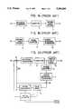
- FIG. 1Ais a block diagram of a conventional encoder
- FIG. 1Bis a block diagram of a conventional decoder
- FIG. 2Ais a block diagram of another conventional encoder
- FIG. 2Bis a block diagram of another conventional decoder
- FIG. 3Ais a block diagram of an encoder according to a first embodiment of the present invention.
- FIG. 3Bis a block diagram of a decoder according to a first embodiment of the present invention.
- FIG. 4Ais a block diagram of an encoder according to another embodiment of the present invention.
- FIG. 4Bis a block diagram of a decoder according to another embodiment of the present invention.
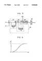
- FIG. 5is a detailed block diagram of a blocking artifact measurer of FIGS. 3A and 4A.
- FIG. 6is a graph which represents an operational characteristic of the blocking artifact measurer of FIG. 5.
- FIGS. 3A and 3Bshow an encoder and a decoder according to a first embodiment of the present invention.
- the encoderincludes an orthogonal transformer 1 for converting the N ⁇ N block data of the picture into transformation coefficients of the frequency domain, and a quantizer 3 and a variable-length-encoder 5 for quantizing and variable-length-encoding the transformation coefficients output from the orthogonal transformer 1 and for compressing the data.
- An inverse quantizer 4receives the quantized data, and together with an inverse orthogonal transformer 2 and first frame memory 6, restores the quantized data into the video data of the spatial domain and reconstructs the frame data.
- a second frame memory 100receives the original video data, and serves to delay the video data for a predetermined period of time prior to the data being discrete cosine transformed in the orthogonal transformer 1.
- a blocking artifact measurer 200receives the delayed original frame data Fo from the second frame memory 100, and generates a post-processing parameter ⁇ which is varied according to the degree of discontinuity of the block boundary portion.
- the first frame memory 6receives the restored block data output from the N ⁇ N inverse orthogonal transformer 2, and sequentially stores the block data to generate the restored frame data Fr.
- the second frame memory 100receives the block data which is applied to the input terminal IN and stores it on a frame unit basis.
- the second frame memory 100delays and outputs the stored frame data Fo after a predetermined period of time so that the output frame of data corresponds to frame of data Fr that is reconstructed and output by the first frame memory 6.
- the blocking artifact measurer 200compares the restored frame data Fr supplied from the first frame memory 6 with the delayed original frame data Fo supplied from second frame memory 100, and measures the degree of blocking artifact at the block boundary portion.
- the measurer 200Based on the measured degree of blocking artifact, the measurer 200 varies and generates the post-processing parameter ⁇ according to the measured degree of blocking artifact.
- the generated post-processing parameter ⁇is transmitted to a decoder along with the encoded video data.
- FIG. 5shows a detailed block diagram of the blocking artifact measurer 200, which includes a fourth adder A4 which receives the delayed original frame data Fo and the restored frame data Fr, and generates a frame data error corresponding to the difference between the frame data Fo and Fr, a discontinuity degree calculator 240 which receives the frame data error output from the fourth adder A4 and calculates a discontinuity degree parameter ⁇ due to the blocking artifact at the block boundary portion, and a read-only-memory (ROM) 250 which receives the calculated discontinuity degree parameter ⁇ and generates the post-processing parameter ⁇ which is varied in proportion to the magnitude of the discontinuity degree parameter ⁇ .
- the ROM 250stores a predetermined look-up table which provides a correlation between the discontinuity degree parameter ⁇ and the post-processing parameter a.
- the characteristic of the look-up tablehas a non-linear proportional relationship as shown in FIG. 6.
- the discontinuity calculator 240includes an error value calculator 210 which receives the frame data error from the fourth adder A4 and calculates the error value between the respective pixels based on the frame data error, a block boundary detector 220 for detecting the error value corresponding to the boundary portion between respective blocks among the error values calculated in the error value calculator 210, and an average error calculator 230 which receives the error values generated by the block boundary detector 220 and generates the average error value corresponding to the discontinuity degree parameter ⁇ at each block boundary with respect to the entire error frame.
- the blocking artifact measurer 200operates as follows.
- the fourth adder A4calculates the frame data error using the delayed original frame data Fo and the restored frame data Fr.
- the frame data error output from the fourth adder A4is applied to one input of a fifth adder A5.
- the frame data erroris also input to a delayer 211, which delays the frame data error by a predetermined period of time and then outputs the delayed signal to the other input of the fifth adder A5.
- the fifth adder A5calculates a difference between both input data.
- the output of the fifth adder A5corresponds to the error value between the respective pixels of the error frame.
- the output of the fifth adder A5is then supplied to the average error calculator 230 via a switch SW3.
- the switch SW3is turned ON or OFF by a control signal supplied from a counter 221.
- the control signal from the counter 221turns the switch SW3 ON only when the error value output from the fifth adder A5 corresponding to each block boundary portion.
- only the error value between the respective pixels of each block boundary portion at the error frameis supplied to the average error calculator 230.
- the average error calculator 230calculates an absolute value mean or a root mean square with respect to the error value applied via the switch SW3, and calculates an average error value with respect to each frame data error.
- the calculated average errorcorresponds to the discontinuity degree parameter ⁇ of each block boundary of each corresponding frame.
- the average error calculator 230is reset to a predetermined initial value (generally "0") by a reset signal RST.
- the reset signal RSTis applied on a per frame unit basis.
- the reset signal RSTcan be applied on a per unit basis where the unit is equal to a field or a predetermined size depending upon the system.
- the discontinuity degree parameter ⁇ output from the average error calculator 230is supplied to the ROM 250.
- the ROM 250outputs the post-processing parameter ⁇ from the look-up table that corresponds to the discontinuity degree parameter ⁇ .
- the post-processing parameter ⁇has a variable real value between "0" and "1" according to the variation of the discontinuity degree parameter ⁇ , as shown in FIG. 6.
- the decoderreceives the encoded transmission data from the encoder of FIG. 3A, and restores the received data to its original state.
- the decoderincludes a variable-length-decoder 11 for variable-length-decoding the received data and converting it into quantized data, an inverse quantizer 12 and inverse orthogonal transformer 13 for inversely quantizing the quantized data, and then converting the inversely quantized data into video data of the spatial domain, and an adaptive low-pass filter 300 for suppressing the blocking artifact.
- the adaptive low-pass filterhas filtering characteristics which are varied according to the post-processing parameter ⁇ that is received with the transmitted data from the encoder.
- the components except for the adaptive low-pass filter 300are known to a person skilled in the art. Accordingly, their detailed descriptions will be omitted.
- the adaptive low-pass filter 300filters the restored video data output from inverse orthogonal transformer 13.
- the filtering characteristicis adaptively varied in accordance with the post-processing parameter ⁇ which is transmitted from the encoder.
- the filtering characteristic H of the adaptive low-pass filter 300is as follows in which the filtering band is varied according to the post-processing parameter a: ##EQU1##
- Lis a low-pass filter coefficient
- Ais an all-pass filter coefficient.
- the equations (2) and (3)represent both the coefficients, respectively.
- the adaptive low-pass filter 300becomes an all-pass filter to pass all the input video data.
- the post-processing parameter ⁇is "1"
- the blocking artifactis severe at the block boundary portion of the corresponding frame.
- the adaptive low-pass filter 300becomes a low-pass filter and filters the block boundary portion of the input video data, thereby removing the blocking artifact component which exists in the block boundary portion.
- the adaptive low-pass filter 300has an intermediate characteristic between the all-pass filter and the low-pass filter, and its filtering band is varied according to the degree of the blocking artifact of the block boundary portion.
- FIGS. 4A and 4Brespectively illustrate an encoder and a decoder according to another embodiment of the present invention.
- the blocking artifact measurer 200is employed with an encoder similar to that as shown in FIGS. 2 which includes a predetermined feedback loop for performing DPCM.
- FIG. 4Athe same components as those shown in FIG. 3A are designated with the same reference symbols. Their detailed descriptions will thus be omitted.
- the feedback loop for effecting DPCMincludes a frame memory 6, motion estimator 7, and motion compensator 8.
- the motion estimator 7receives the N ⁇ N block data from the input terminal IN, and estimates the amount of motion between the input block data and the block data having the most similar pattern to the input block data among the frame data stored in the frame memory 6 so as to generate a motion vector MV.
- the motion compensator 8extracts the corresponding block from the frame data stored in the frame memory 6 according to the motion vector supplied from the motion estimator 7, and supplies the extracted block data to the first adder A1 and the second adder A2.
- the first addercalculates the difference between the block data applied via the input terminal IN and the block data supplied from the motion compensator 8.
- the error datais encoded and transmitted.
- the second adder A2adds the block data supplied from the motion compensator 8 to the restored error data supplied from the inverse orthogonal transformer 2, so as to supply the result to frame memory 6.
- the blocking artifact measurer 200as shown in FIG. 4A, is identical in construction and operation to that which is shown in FIG. 5.
- the decoderdecodes the signal encoded by the encoder of FIG. 4A.
- the feedback loop for restoring the DPCM dataincludes a frame memory 14 and a motion compensator 15.
- the motion compensator 15receives the motion vector MV transmitted from the encoder, and extracts the corresponding block data from among the frame data stored in the frame memory 14 to supply the extracted data to a third adder A3.
- the third adder A3adds the output data of the inverse orthogonal transformer 13 to the output data of the motion compensator 15.
- the adaptive low-pass filter 300receives the post-processing parameter ⁇ which is output and transmitted from the blocking artifact measurer 200 of the encoder, and adaptively filters the video data supplied from the third adder A3 according to the parameter a, thereby reducing the blocking artifact of the block boundary portion.
- the operational characteristics of the adaptive low-pass filter 300are the same as that described above. Accordingly, the adaptive low-pass filter 300 functions as an all-pass filter when the post-processing parameter ⁇ is "0" while it functions as a low-pass filter when the parameter ⁇ is "1 ". When the parameter ⁇ is between "0" and "1" the filtering characteristic is varied according to the magnitude of the parameter a.
- the degree of discontinuity of the block boundaryis calculated using the frame data error corresponding to the difference between the delayed original frame data Fo and the restored frame data Fr.
- the degree of discontinuity of the block boundary portion of the delayed original frameis very small, the discontinuity degree of the block boundary can be directly calculated using only the restored frame data without using the frame data error, and still sufficiently reduce the blocking artifact. In this case, the composition of the system becomes somewhat simplified.
- the left, right, up, and down discontinuity degrees between the blocksare measured and the measured values are added.
- the compositionbecomes complicated in hardware.
- the degree of discontinuity with respect to several samples taken from the picturecan also be measured.
Landscapes
- Engineering & Computer Science (AREA)
- Multimedia (AREA)
- Signal Processing (AREA)
- Compression Or Coding Systems Of Tv Signals (AREA)
- Compression, Expansion, Code Conversion, And Decoders (AREA)
Abstract
Description
Claims (22)
Applications Claiming Priority (2)
| Application Number | Priority Date | Filing Date | Title |
|---|---|---|---|
| KR1019920008362AKR0148130B1 (en) | 1992-05-18 | 1992-05-18 | Apparatus and method for encoding/decoding due to restrain blocking artifact |
| KR92-8362 | 1992-05-18 |
Publications (1)
| Publication Number | Publication Date |
|---|---|
| US5384849Atrue US5384849A (en) | 1995-01-24 |
Family
ID=19333219
Family Applications (1)
| Application Number | Title | Priority Date | Filing Date |
|---|---|---|---|
| US08/062,599Expired - LifetimeUS5384849A (en) | 1992-05-18 | 1993-05-18 | Apparatus and method for encoding/decoding data including the suppression of blocking artifacts |
Country Status (7)
| Country | Link |
|---|---|
| US (1) | US5384849A (en) |
| EP (1) | EP0571171B1 (en) |
| JP (1) | JP2728619B2 (en) |
| KR (1) | KR0148130B1 (en) |
| CN (1) | CN1050489C (en) |
| DE (1) | DE69316439T2 (en) |
| RU (1) | RU2072562C1 (en) |
Cited By (60)
| Publication number | Priority date | Publication date | Assignee | Title |
|---|---|---|---|---|
| US5513301A (en)* | 1993-11-22 | 1996-04-30 | Nec Corporation | Image compression and decompression apparatus with reduced frame memory |
| US5515437A (en)* | 1993-08-23 | 1996-05-07 | Matsushita Electric Industrial Co., Ltd. | Scramble transmission apparatus and signal processing apparatus |
| US5535275A (en)* | 1993-07-08 | 1996-07-09 | Sony Corporation | Apparatus and method for producing scrambled digital video signals |
| US5563662A (en)* | 1993-05-11 | 1996-10-08 | Olympus Optical Co., Ltd. | Image signal compressing and expansion with filter means to eliminate blocking effect |
| US5590064A (en)* | 1994-10-26 | 1996-12-31 | Intel Corporation | Post-filtering for decoded video signals |
| US5590222A (en)* | 1993-11-15 | 1996-12-31 | Sony Corporation | Image signal processing apparatus utilizing a 2D Haar transform and adaptive selection of images based on a parameter such as a ratio of coefficients for reducing block distortion and method thereof |
| US5619267A (en)* | 1993-02-26 | 1997-04-08 | U.S. Philips Corporation | Video decoder including a control unit |
| US5625714A (en)* | 1991-01-10 | 1997-04-29 | Olympus Optical Co., Ltd. | Image signal decoding device capable of removing block distortion with simple structure |
| US5629778A (en)* | 1995-05-15 | 1997-05-13 | Polaroid Corporation | Method and apparatus for reduction of image data compression noise |
| US5677980A (en)* | 1995-06-20 | 1997-10-14 | Nippon Steel Corporation | Decoder for compressed digital signal |
| US5694489A (en)* | 1994-10-20 | 1997-12-02 | Olympus Optical Co., Ltd. | Image signal processing apparatus with no change of signal processing mode in compression/expansion processing loop |
| US5694492A (en)* | 1994-04-30 | 1997-12-02 | Daewoo Electronics Co., Ltd | Post-processing method and apparatus for removing a blocking effect in a decoded image signal |
| US5708509A (en)* | 1993-11-09 | 1998-01-13 | Asahi Kogaku Kogyo Kabushiki Kaisha | Digital data processing device |
| US5715006A (en)* | 1993-09-28 | 1998-02-03 | Nec Corporation | apparatus for and method of motion compensation with boundarycorrection for moving picture |
| US5734757A (en)* | 1995-04-29 | 1998-03-31 | Daewoo Electronics, Co., Ltd. | Post-processing method and apparatus for use in an image signal decoding system |
| US5787210A (en)* | 1994-10-31 | 1998-07-28 | Daewood Electronics, Co., Ltd. | Post-processing method for use in an image signal decoding system |
| US5832120A (en)* | 1995-12-22 | 1998-11-03 | Cirrus Logic, Inc. | Universal MPEG decoder with scalable picture size |
| US5841909A (en)* | 1993-06-28 | 1998-11-24 | Nec Corporation | Method of generating an orthogonal basis function set in an image processing system |
| US5844614A (en)* | 1995-01-09 | 1998-12-01 | Matsushita Electric Industrial Co., Ltd. | Video signal decoding apparatus |
| US5847764A (en)* | 1995-01-10 | 1998-12-08 | Sony Corporation | Reduction of image information distoration by adaptively band-limiting the image information as a function of at least a quantizing value |
| US5920356A (en)* | 1995-06-06 | 1999-07-06 | Compressions Labs, Inc. | Coding parameter adaptive transform artifact reduction process |
| US5936673A (en)* | 1995-05-26 | 1999-08-10 | Intel Corporation | Temporal tile staggering for block based video compression |
| US5953456A (en)* | 1995-09-05 | 1999-09-14 | Canon Kabushiki Kaisha | Recording apparatus for repetitively recording image data of same frame and reproducing apparatus |
| KR100230842B1 (en)* | 1996-05-14 | 1999-11-15 | 배순훈 | Block cancelation method and apparatus in moving picture decoder |
| KR100230840B1 (en)* | 1996-05-14 | 1999-11-15 | 배순훈 | The block cancelation method and apparatus in moving picture decoder |
| KR100230839B1 (en)* | 1996-05-14 | 1999-11-15 | 전주범 | Block cancelation method and apparatus in moving picture decoder |
| KR100230841B1 (en)* | 1996-05-14 | 1999-11-15 | 전주범 | Block cancelation method and apparatus in moving picture decoder |
| US6005982A (en)* | 1996-08-29 | 1999-12-21 | Asahi Kogaku Kogyo Kabushiki Kaisha | Image compression and expansion device |
| US6038345A (en)* | 1994-05-26 | 2000-03-14 | Canon Kabushiki Kaisha | Apparatus for encoding/decoding image data |
| US6111915A (en)* | 1997-03-24 | 2000-08-29 | Oki Electric Industry Co., Ltd. | Picture decoder |
| US6144768A (en)* | 1996-04-30 | 2000-11-07 | Texas Instruments Incorporated | Method of decoding image data |
| US6298161B1 (en)* | 1997-02-28 | 2001-10-02 | Lg Electronics Inc. | Apparatus and method for decoding digital image with function of suppressing blocking effect |
| US6370279B1 (en)* | 1997-04-10 | 2002-04-09 | Samsung Electronics Co., Ltd. | Block-based image processing method and apparatus therefor |
| RU2189120C2 (en)* | 1996-09-09 | 2002-09-10 | Сони Корпорейшн | Image coding and decoding |
| US20020126912A1 (en)* | 2000-12-26 | 2002-09-12 | Rouvellou Laurent Jean Marie | Data processing method |
| US6463182B1 (en)* | 1995-12-28 | 2002-10-08 | Canon Kabushiki Kaisha | Image processing apparatus and method for removing noise near an edge of an image |
| US6496582B1 (en)* | 1996-01-26 | 2002-12-17 | Canon Kabushiki Kaisha | Information processing apparatus and method therefor |
| US20030223501A1 (en)* | 2002-06-04 | 2003-12-04 | Koninklijke Philips Electronics N.V. | Video decoding system and method having post-processing to reduce sharpness prediction drift |
| US6738528B1 (en)* | 1998-05-22 | 2004-05-18 | Matsushita Electric Industrial Co., Ltd. | Block noise detector and block noise eliminator |
| US6741277B1 (en) | 2000-01-13 | 2004-05-25 | Koninklijke Philips Electronics N.V. | System and method for automated testing of digital television receivers |
| US20040210763A1 (en)* | 2002-11-06 | 2004-10-21 | Systems Research & Development | Confidential data sharing and anonymous entity resolution |
| US20050053302A1 (en)* | 2003-09-07 | 2005-03-10 | Microsoft Corporation | Interlace frame lapped transform |
| US20050053150A1 (en)* | 2003-09-07 | 2005-03-10 | Microsoft Corporation | Conditional lapped transform |
| US20060133682A1 (en)* | 2004-12-17 | 2006-06-22 | Microsoft Corporation | Reversible overlap operator for efficient lossless data compression |
| US20060133683A1 (en)* | 2004-12-17 | 2006-06-22 | Microsoft Corporation | Reversible transform for lossy and lossless 2-D data compression |
| US20060133684A1 (en)* | 2004-12-17 | 2006-06-22 | Microsoft Corporation | Reversible 2-dimensional pre-/post-filtering for lapped biorthogonal transform |
| US20070036225A1 (en)* | 2005-08-12 | 2007-02-15 | Microsoft Corporation | SIMD lapped transform-based digital media encoding/decoding |
| US7248302B1 (en)* | 1999-09-30 | 2007-07-24 | Koninklijke Philips Electronics N.V. | Picture signal processing |
| US20070236507A1 (en)* | 2006-04-11 | 2007-10-11 | Idelix Software Inc. | Method and system for transparency adjustment and occlusion resolution for urban landscape visualization |
| US20070239705A1 (en)* | 2006-03-29 | 2007-10-11 | International Business Machines Corporation | System and method for performing a similarity measure of anonymized data |
| US20080114991A1 (en)* | 2006-11-13 | 2008-05-15 | International Business Machines Corporation | Post-anonymous fuzzy comparisons without the use of pre-anonymization variants |
| US20080226183A1 (en)* | 2007-03-16 | 2008-09-18 | Shawmin Lei | DPCM with Adaptive Range and PCM Escape Mode |
| US7471726B2 (en) | 2003-07-15 | 2008-12-30 | Microsoft Corporation | Spatial-domain lapped transform in digital media compression |
| US20090290045A1 (en)* | 2005-06-16 | 2009-11-26 | Sony Corporation | Image Data Processing Apparatus, Image Data Processing Method, And Program |
| US20090297054A1 (en)* | 2008-05-27 | 2009-12-03 | Microsoft Corporation | Reducing dc leakage in hd photo transform |
| US20090299754A1 (en)* | 2008-05-30 | 2009-12-03 | Microsoft Corporation | Factorization of overlapping tranforms into two block transforms |
| US20100067574A1 (en)* | 2007-10-15 | 2010-03-18 | Florian Knicker | Video decoding method and video encoding method |
| US20100086058A1 (en)* | 1997-07-30 | 2010-04-08 | Video Enhancement Solutions LLC | Method of reducing a blocking artifact when coding moving picture |
| US20100092098A1 (en)* | 2008-10-10 | 2010-04-15 | Microsoft Corporation | Reduced dc gain mismatch and dc leakage in overlap transform processing |
| US11483571B2 (en) | 2011-03-09 | 2022-10-25 | Nec Corporation | Video decoding device and method using inverse quantization |
Families Citing this family (24)
| Publication number | Priority date | Publication date | Assignee | Title |
|---|---|---|---|---|
| KR0128881B1 (en)* | 1994-04-30 | 1998-04-10 | 배순훈 | Digital image decoder |
| JPH0837662A (en)* | 1994-07-22 | 1996-02-06 | Hitachi Ltd | Image encoding / decoding device |
| FI97495C (en)* | 1995-02-06 | 1996-12-27 | Nokia Technology Gmbh | Procedure for sharpening an image |
| US6324301B1 (en)* | 1996-01-24 | 2001-11-27 | Lucent Technologies Inc. | Adaptive postfilter for low bitrate visual telephony noise removal |
| US5881180A (en)* | 1996-02-08 | 1999-03-09 | Sony Corporation | Method and apparatus for the reduction of blocking effects in images |
| US5974196A (en)* | 1996-03-15 | 1999-10-26 | Sony Corporation | Method and apparatus for blocking effect reduction in images |
| US5933542A (en)* | 1996-04-24 | 1999-08-03 | Sony Corporation | Method and apparatus for blocking effect reduction in images by post-processing in the spatial domain |
| US5796875A (en)* | 1996-08-13 | 1998-08-18 | Sony Electronics, Inc. | Selective de-blocking filter for DCT compressed images |
| FI106071B (en) | 1997-03-13 | 2000-11-15 | Nokia Mobile Phones Ltd | Adaptive filter |
| DE19718063C2 (en)* | 1997-04-29 | 2001-05-17 | Rohde & Schwarz | Method for detecting and quantifying image changes in a video image that is processed with a block-based, data-reducing video code |
| JP4306061B2 (en)* | 1999-03-26 | 2009-07-29 | 日本ビクター株式会社 | Block noise detector |
| DE19926194C2 (en)* | 1999-06-09 | 2001-05-10 | Datasound Gmbh | Data strips and methods for encoding and decoding printed data |
| RU2159470C1 (en)* | 1999-07-23 | 2000-11-20 | Поволжская государственная академия телекоммуникаций и информатики | Device for detection and correction of anomalous digital errors for voice transmission using pulse-code modulation |
| FR2821458A1 (en)* | 2001-02-28 | 2002-08-30 | Koninkl Philips Electronics Nv | SCHEME, SYNTAX ANALYSIS METHOD, AND METHOD FOR GENERATING A BINARY STREAM FROM A SCHEME |
| US7450641B2 (en)* | 2001-09-14 | 2008-11-11 | Sharp Laboratories Of America, Inc. | Adaptive filtering based upon boundary strength |
| EP1431919B1 (en)* | 2002-12-05 | 2010-03-03 | Samsung Electronics Co., Ltd. | Method and apparatus for encoding and decoding three-dimensional object data by using octrees |
| US20050094003A1 (en)* | 2003-11-05 | 2005-05-05 | Per Thorell | Methods of processing digital image and/or video data including luminance filtering based on chrominance data and related systems and computer program products |
| AU2005239628B2 (en)* | 2005-01-14 | 2010-08-05 | Microsoft Technology Licensing, Llc | Reversible 2-dimensional pre-/post-filtering for lapped biorthogonal transform |
| US8121421B2 (en) | 2005-09-28 | 2012-02-21 | Telefonaktiebolaget L M Ericsson (Publ) | Media content management |
| US7873224B2 (en) | 2006-03-01 | 2011-01-18 | Qualcomm Incorporated | Enhanced image/video quality through artifact evaluation |
| US7925086B2 (en)* | 2007-01-18 | 2011-04-12 | Samsung Electronics Co, Ltd. | Method and system for adaptive quantization layer reduction in image processing applications |
| GB201119206D0 (en) | 2011-11-07 | 2011-12-21 | Canon Kk | Method and device for providing compensation offsets for a set of reconstructed samples of an image |
| US10347333B2 (en)* | 2017-02-16 | 2019-07-09 | Micron Technology, Inc. | Efficient utilization of memory die area |
| KR20210133395A (en)* | 2020-04-29 | 2021-11-08 | 삼성전자주식회사 | An image encoder, an image sensing device, and an operating method of the image encoder |
Citations (2)
| Publication number | Priority date | Publication date | Assignee | Title |
|---|---|---|---|---|
| US4754492A (en)* | 1985-06-03 | 1988-06-28 | Picturetel Corporation | Method and system for adapting a digitized signal processing system for block processing with minimal blocking artifacts |
| US5121216A (en)* | 1989-07-19 | 1992-06-09 | Bell Communications Research | Adaptive transform coding of still images |
Family Cites Families (7)
| Publication number | Priority date | Publication date | Assignee | Title |
|---|---|---|---|---|
| JP2801609B2 (en)* | 1988-08-26 | 1998-09-21 | 富士通株式会社 | Adaptive filter of image coding device |
| JPH0832047B2 (en)* | 1989-04-28 | 1996-03-27 | 日本ビクター株式会社 | Predictive coding device |
| US5146326A (en)* | 1989-11-14 | 1992-09-08 | Fujitsu Limited | Coded picture information decoding apparatus having means for improving picture distortion |
| JPH03167962A (en)* | 1989-11-28 | 1991-07-19 | Fujitsu Ltd | Block distortion improving system |
| JPH04970A (en)* | 1990-04-18 | 1992-01-06 | Fuji Photo Film Co Ltd | Picture signal decoding and reproducing device |
| US5229864A (en)* | 1990-04-16 | 1993-07-20 | Fuji Photo Film Co., Ltd. | Device for regenerating a picture signal by decoding |
| US5454051A (en)* | 1991-08-05 | 1995-09-26 | Eastman Kodak Company | Method of reducing block artifacts created by block transform compression algorithms |
- 1992
- 1992-05-18KRKR1019920008362Apatent/KR0148130B1/ennot_activeExpired - Lifetime
- 1993
- 1993-04-26JPJP9983093Apatent/JP2728619B2/ennot_activeExpired - Lifetime
- 1993-05-17RURU93005310Apatent/RU2072562C1/enactive
- 1993-05-18EPEP19930303814patent/EP0571171B1/ennot_activeExpired - Lifetime
- 1993-05-18DEDE69316439Tpatent/DE69316439T2/ennot_activeExpired - Lifetime
- 1993-05-18CNCN93106014Apatent/CN1050489C/ennot_activeExpired - Lifetime
- 1993-05-18USUS08/062,599patent/US5384849A/ennot_activeExpired - Lifetime
Patent Citations (2)
| Publication number | Priority date | Publication date | Assignee | Title |
|---|---|---|---|---|
| US4754492A (en)* | 1985-06-03 | 1988-06-28 | Picturetel Corporation | Method and system for adapting a digitized signal processing system for block processing with minimal blocking artifacts |
| US5121216A (en)* | 1989-07-19 | 1992-06-09 | Bell Communications Research | Adaptive transform coding of still images |
Cited By (88)
| Publication number | Priority date | Publication date | Assignee | Title |
|---|---|---|---|---|
| US5787204A (en)* | 1991-01-10 | 1998-07-28 | Olympus Optical Co., Ltd. | Image signal decoding device capable of removing block distortion with simple structure |
| US5625714A (en)* | 1991-01-10 | 1997-04-29 | Olympus Optical Co., Ltd. | Image signal decoding device capable of removing block distortion with simple structure |
| US5619267A (en)* | 1993-02-26 | 1997-04-08 | U.S. Philips Corporation | Video decoder including a control unit |
| US5563662A (en)* | 1993-05-11 | 1996-10-08 | Olympus Optical Co., Ltd. | Image signal compressing and expansion with filter means to eliminate blocking effect |
| US5841909A (en)* | 1993-06-28 | 1998-11-24 | Nec Corporation | Method of generating an orthogonal basis function set in an image processing system |
| US5535275A (en)* | 1993-07-08 | 1996-07-09 | Sony Corporation | Apparatus and method for producing scrambled digital video signals |
| US5515437A (en)* | 1993-08-23 | 1996-05-07 | Matsushita Electric Industrial Co., Ltd. | Scramble transmission apparatus and signal processing apparatus |
| US5715006A (en)* | 1993-09-28 | 1998-02-03 | Nec Corporation | apparatus for and method of motion compensation with boundarycorrection for moving picture |
| US5708509A (en)* | 1993-11-09 | 1998-01-13 | Asahi Kogaku Kogyo Kabushiki Kaisha | Digital data processing device |
| US5590222A (en)* | 1993-11-15 | 1996-12-31 | Sony Corporation | Image signal processing apparatus utilizing a 2D Haar transform and adaptive selection of images based on a parameter such as a ratio of coefficients for reducing block distortion and method thereof |
| US5513301A (en)* | 1993-11-22 | 1996-04-30 | Nec Corporation | Image compression and decompression apparatus with reduced frame memory |
| US5694492A (en)* | 1994-04-30 | 1997-12-02 | Daewoo Electronics Co., Ltd | Post-processing method and apparatus for removing a blocking effect in a decoded image signal |
| US6038345A (en)* | 1994-05-26 | 2000-03-14 | Canon Kabushiki Kaisha | Apparatus for encoding/decoding image data |
| US5694489A (en)* | 1994-10-20 | 1997-12-02 | Olympus Optical Co., Ltd. | Image signal processing apparatus with no change of signal processing mode in compression/expansion processing loop |
| US5590064A (en)* | 1994-10-26 | 1996-12-31 | Intel Corporation | Post-filtering for decoded video signals |
| US5787210A (en)* | 1994-10-31 | 1998-07-28 | Daewood Electronics, Co., Ltd. | Post-processing method for use in an image signal decoding system |
| US5844614A (en)* | 1995-01-09 | 1998-12-01 | Matsushita Electric Industrial Co., Ltd. | Video signal decoding apparatus |
| US5847764A (en)* | 1995-01-10 | 1998-12-08 | Sony Corporation | Reduction of image information distoration by adaptively band-limiting the image information as a function of at least a quantizing value |
| US5734757A (en)* | 1995-04-29 | 1998-03-31 | Daewoo Electronics, Co., Ltd. | Post-processing method and apparatus for use in an image signal decoding system |
| US5629778A (en)* | 1995-05-15 | 1997-05-13 | Polaroid Corporation | Method and apparatus for reduction of image data compression noise |
| US5936673A (en)* | 1995-05-26 | 1999-08-10 | Intel Corporation | Temporal tile staggering for block based video compression |
| US6473463B2 (en) | 1995-05-26 | 2002-10-29 | Intel Corporation | Temporal tile staggering for block based video compression |
| US6246719B1 (en)* | 1995-05-26 | 2001-06-12 | Intel Corporation | Temporal tile staggering for block based video compression |
| US5920356A (en)* | 1995-06-06 | 1999-07-06 | Compressions Labs, Inc. | Coding parameter adaptive transform artifact reduction process |
| US5677980A (en)* | 1995-06-20 | 1997-10-14 | Nippon Steel Corporation | Decoder for compressed digital signal |
| US5953456A (en)* | 1995-09-05 | 1999-09-14 | Canon Kabushiki Kaisha | Recording apparatus for repetitively recording image data of same frame and reproducing apparatus |
| US5832120A (en)* | 1995-12-22 | 1998-11-03 | Cirrus Logic, Inc. | Universal MPEG decoder with scalable picture size |
| US6463182B1 (en)* | 1995-12-28 | 2002-10-08 | Canon Kabushiki Kaisha | Image processing apparatus and method for removing noise near an edge of an image |
| US6496582B1 (en)* | 1996-01-26 | 2002-12-17 | Canon Kabushiki Kaisha | Information processing apparatus and method therefor |
| US6144768A (en)* | 1996-04-30 | 2000-11-07 | Texas Instruments Incorporated | Method of decoding image data |
| KR100230840B1 (en)* | 1996-05-14 | 1999-11-15 | 배순훈 | The block cancelation method and apparatus in moving picture decoder |
| KR100230841B1 (en)* | 1996-05-14 | 1999-11-15 | 전주범 | Block cancelation method and apparatus in moving picture decoder |
| KR100230842B1 (en)* | 1996-05-14 | 1999-11-15 | 배순훈 | Block cancelation method and apparatus in moving picture decoder |
| KR100230839B1 (en)* | 1996-05-14 | 1999-11-15 | 전주범 | Block cancelation method and apparatus in moving picture decoder |
| US6005982A (en)* | 1996-08-29 | 1999-12-21 | Asahi Kogaku Kogyo Kabushiki Kaisha | Image compression and expansion device |
| RU2189120C2 (en)* | 1996-09-09 | 2002-09-10 | Сони Корпорейшн | Image coding and decoding |
| US6298161B1 (en)* | 1997-02-28 | 2001-10-02 | Lg Electronics Inc. | Apparatus and method for decoding digital image with function of suppressing blocking effect |
| US6111915A (en)* | 1997-03-24 | 2000-08-29 | Oki Electric Industry Co., Ltd. | Picture decoder |
| US6370279B1 (en)* | 1997-04-10 | 2002-04-09 | Samsung Electronics Co., Ltd. | Block-based image processing method and apparatus therefor |
| US8983225B2 (en)* | 1997-07-30 | 2015-03-17 | Lg Electronics Inc. | Method of reducing a blocking artifact when coding moving picture |
| US9456221B2 (en) | 1997-07-30 | 2016-09-27 | Lg Electronics Inc. | Method of reducing a blocking artifact when coding moving picture |
| US20100086058A1 (en)* | 1997-07-30 | 2010-04-08 | Video Enhancement Solutions LLC | Method of reducing a blocking artifact when coding moving picture |
| US6738528B1 (en)* | 1998-05-22 | 2004-05-18 | Matsushita Electric Industrial Co., Ltd. | Block noise detector and block noise eliminator |
| US7248302B1 (en)* | 1999-09-30 | 2007-07-24 | Koninklijke Philips Electronics N.V. | Picture signal processing |
| US6741277B1 (en) | 2000-01-13 | 2004-05-25 | Koninklijke Philips Electronics N.V. | System and method for automated testing of digital television receivers |
| US20020126912A1 (en)* | 2000-12-26 | 2002-09-12 | Rouvellou Laurent Jean Marie | Data processing method |
| US6950562B2 (en)* | 2000-12-26 | 2005-09-27 | Koninklijke Philips Electronics N.V. | Data processing method |
| US20030223501A1 (en)* | 2002-06-04 | 2003-12-04 | Koninklijke Philips Electronics N.V. | Video decoding system and method having post-processing to reduce sharpness prediction drift |
| US6980599B2 (en)* | 2002-06-04 | 2005-12-27 | Koninklijke Philips Electronics N.V. | Video decoding system and method having post-processing to reduce sharpness prediction drift |
| US20040210763A1 (en)* | 2002-11-06 | 2004-10-21 | Systems Research & Development | Confidential data sharing and anonymous entity resolution |
| US7900052B2 (en) | 2002-11-06 | 2011-03-01 | International Business Machines Corporation | Confidential data sharing and anonymous entity resolution |
| US7471726B2 (en) | 2003-07-15 | 2008-12-30 | Microsoft Corporation | Spatial-domain lapped transform in digital media compression |
| US20050053302A1 (en)* | 2003-09-07 | 2005-03-10 | Microsoft Corporation | Interlace frame lapped transform |
| US7369709B2 (en) | 2003-09-07 | 2008-05-06 | Microsoft Corporation | Conditional lapped transform |
| US20050053150A1 (en)* | 2003-09-07 | 2005-03-10 | Microsoft Corporation | Conditional lapped transform |
| WO2005027492A3 (en)* | 2003-09-07 | 2006-11-23 | Microsoft Corp | Conditional lapped transform |
| US7412102B2 (en) | 2003-09-07 | 2008-08-12 | Microsoft Corporation | Interlace frame lapped transform |
| US7305139B2 (en) | 2004-12-17 | 2007-12-04 | Microsoft Corporation | Reversible 2-dimensional pre-/post-filtering for lapped biorthogonal transform |
| CN1791222B (en)* | 2004-12-17 | 2012-08-15 | 微软公司 | Reversible transform for lossy and lossless 2-D data compression |
| US20060133684A1 (en)* | 2004-12-17 | 2006-06-22 | Microsoft Corporation | Reversible 2-dimensional pre-/post-filtering for lapped biorthogonal transform |
| US20060133683A1 (en)* | 2004-12-17 | 2006-06-22 | Microsoft Corporation | Reversible transform for lossy and lossless 2-D data compression |
| US7428342B2 (en) | 2004-12-17 | 2008-09-23 | Microsoft Corporation | Reversible overlap operator for efficient lossless data compression |
| US20080317368A1 (en)* | 2004-12-17 | 2008-12-25 | Microsoft Corporation | Reversible overlap operator for efficient lossless data compression |
| US7471850B2 (en) | 2004-12-17 | 2008-12-30 | Microsoft Corporation | Reversible transform for lossy and lossless 2-D data compression |
| US20060133682A1 (en)* | 2004-12-17 | 2006-06-22 | Microsoft Corporation | Reversible overlap operator for efficient lossless data compression |
| US7551789B2 (en) | 2004-12-17 | 2009-06-23 | Microsoft Corporation | Reversible overlap operator for efficient lossless data compression |
| US8233060B2 (en)* | 2005-06-16 | 2012-07-31 | Sony Corporation | Image data processing apparatus, image data processing method, and program |
| US20090290045A1 (en)* | 2005-06-16 | 2009-11-26 | Sony Corporation | Image Data Processing Apparatus, Image Data Processing Method, And Program |
| US20070036225A1 (en)* | 2005-08-12 | 2007-02-15 | Microsoft Corporation | SIMD lapped transform-based digital media encoding/decoding |
| US8036274B2 (en) | 2005-08-12 | 2011-10-11 | Microsoft Corporation | SIMD lapped transform-based digital media encoding/decoding |
| US8204213B2 (en)* | 2006-03-29 | 2012-06-19 | International Business Machines Corporation | System and method for performing a similarity measure of anonymized data |
| US20070239705A1 (en)* | 2006-03-29 | 2007-10-11 | International Business Machines Corporation | System and method for performing a similarity measure of anonymized data |
| US20070236507A1 (en)* | 2006-04-11 | 2007-10-11 | Idelix Software Inc. | Method and system for transparency adjustment and occlusion resolution for urban landscape visualization |
| US20080114991A1 (en)* | 2006-11-13 | 2008-05-15 | International Business Machines Corporation | Post-anonymous fuzzy comparisons without the use of pre-anonymization variants |
| US8204831B2 (en) | 2006-11-13 | 2012-06-19 | International Business Machines Corporation | Post-anonymous fuzzy comparisons without the use of pre-anonymization variants |
| US20080226183A1 (en)* | 2007-03-16 | 2008-09-18 | Shawmin Lei | DPCM with Adaptive Range and PCM Escape Mode |
| US8107751B2 (en)* | 2007-03-16 | 2012-01-31 | Sharp Laboratories Of America, Inc. | DPCM with adaptive range and PCM escape mode |
| US20100067574A1 (en)* | 2007-10-15 | 2010-03-18 | Florian Knicker | Video decoding method and video encoding method |
| US20090297054A1 (en)* | 2008-05-27 | 2009-12-03 | Microsoft Corporation | Reducing dc leakage in hd photo transform |
| US8369638B2 (en) | 2008-05-27 | 2013-02-05 | Microsoft Corporation | Reducing DC leakage in HD photo transform |
| US8724916B2 (en) | 2008-05-27 | 2014-05-13 | Microsoft Corporation | Reducing DC leakage in HD photo transform |
| US8447591B2 (en) | 2008-05-30 | 2013-05-21 | Microsoft Corporation | Factorization of overlapping tranforms into two block transforms |
| US20090299754A1 (en)* | 2008-05-30 | 2009-12-03 | Microsoft Corporation | Factorization of overlapping tranforms into two block transforms |
| US20100092098A1 (en)* | 2008-10-10 | 2010-04-15 | Microsoft Corporation | Reduced dc gain mismatch and dc leakage in overlap transform processing |
| US8275209B2 (en) | 2008-10-10 | 2012-09-25 | Microsoft Corporation | Reduced DC gain mismatch and DC leakage in overlap transform processing |
| US11483571B2 (en) | 2011-03-09 | 2022-10-25 | Nec Corporation | Video decoding device and method using inverse quantization |
| US11496749B2 (en) | 2011-03-09 | 2022-11-08 | Nec Corporation | Video decoding device and method using inverse quantization |
| US11509909B2 (en)* | 2011-03-09 | 2022-11-22 | Nec Corporation | Video decoding device and method using inverse quantization |
Also Published As
| Publication number | Publication date |
|---|---|
| EP0571171A2 (en) | 1993-11-24 |
| JPH0722962A (en) | 1995-01-24 |
| KR0148130B1 (en) | 1998-09-15 |
| DE69316439D1 (en) | 1998-02-26 |
| RU2072562C1 (en) | 1997-01-27 |
| EP0571171B1 (en) | 1998-01-21 |
| CN1050489C (en) | 2000-03-15 |
| DE69316439T2 (en) | 1998-08-13 |
| EP0571171A3 (en) | 1994-08-10 |
| CN1081807A (en) | 1994-02-09 |
| KR930024496A (en) | 1993-12-22 |
| JP2728619B2 (en) | 1998-03-18 |
Similar Documents
| Publication | Publication Date | Title |
|---|---|---|
| US5384849A (en) | Apparatus and method for encoding/decoding data including the suppression of blocking artifacts | |
| EP0779742B1 (en) | Noise estimation and reduction apparatus for video signal processing | |
| US5754793A (en) | Wavelet image compression/recovery apparatus and method using human visual system modeling | |
| KR100213018B1 (en) | Video encoding device | |
| JP3025610B2 (en) | Encoding method and apparatus | |
| US20060182356A1 (en) | Video compression and decompression system with postfilter to filter coding artifacts | |
| KR0159559B1 (en) | Adaptive Post-Processing of Digital Images | |
| EP0714210B1 (en) | Method of reducing mosquito noise generated during decoding process of image data and device for decoding image data using the same | |
| US5515105A (en) | Video signal coder using variance controlled quantization | |
| US5392073A (en) | Motion estimating device for variable length encoded data | |
| EP0784410A2 (en) | Image coded data processing | |
| US5508745A (en) | Apparatus for controlling a quantization level to be modified by a motion vector | |
| JPH066829A (en) | Method and apparatus for compressing image data | |
| JPS63284974A (en) | Picture compression system | |
| KR0128858B1 (en) | Encoding mode determination device for screen change | |
| KR100229791B1 (en) | Adaptive Video Coding System with Band Limit Function | |
| KR0148150B1 (en) | Adaptive Quantization Step Size Determination Method According to Complexity of Image Data and Its Apparatus | |
| KR100229792B1 (en) | Improved image coding system having functions for adaptively determining image coding mode | |
| KR19980017211A (en) | Improved Image Decoding System | |
| KR0178711B1 (en) | Coding and Decoding System Using Adaptive Post Processing | |
| KR0147952B1 (en) | Video encoding device | |
| KR0124158B1 (en) | Image decoding apparatus and method capable of adaptive post-processing | |
| KR950007304B1 (en) | Optimum data compressing mehtod of video encoder | |
| KR0128877B1 (en) | Method for decision central value of quantizer in moving image ending system51 h 04 n 7/24 | |
| JP3191433B2 (en) | High efficiency coding device |
Legal Events
| Date | Code | Title | Description |
|---|---|---|---|
| STPP | Information on status: patent application and granting procedure in general | Free format text:APPLICATION UNDERGOING PREEXAM PROCESSING | |
| AS | Assignment | Owner name:SAMSUNG ELECTRONICS CO., LTD., JAPAN Free format text:ASSIGNMENT OF ASSIGNORS INTEREST;ASSIGNOR:JEONG, JE-CHANG;REEL/FRAME:006666/0351 Effective date:19930618 | |
| AS | Assignment | Owner name:SAMSUNG ELECTRONICS CO., LTD., KOREA, REPUBLIC OF Free format text:CORRECTIVE ASSIGNMENT TO CORRECT ASSIGNEE'S ADDRESS. DOCUMENT PREVIOUSLY RECORDED AT REEL 6666 FRAMES 351;ASSIGNOR:JEONG, JE-CHANG;REEL/FRAME:006748/0341 Effective date:19930618 | |
| FEPP | Fee payment procedure | Free format text:PAYOR NUMBER ASSIGNED (ORIGINAL EVENT CODE: ASPN); ENTITY STATUS OF PATENT OWNER: LARGE ENTITY | |
| FPAY | Fee payment | Year of fee payment:4 | |
| SULP | Surcharge for late payment | ||
| FEPP | Fee payment procedure | Free format text:PAYER NUMBER DE-ASSIGNED (ORIGINAL EVENT CODE: RMPN); ENTITY STATUS OF PATENT OWNER: LARGE ENTITY Free format text:PAYOR NUMBER ASSIGNED (ORIGINAL EVENT CODE: ASPN); ENTITY STATUS OF PATENT OWNER: LARGE ENTITY | |
| FPAY | Fee payment | Year of fee payment:8 | |
| FPAY | Fee payment | Year of fee payment:12 |