US5383907A - System and method for delivering multiple closely spaced defibrillation pulses - Google Patents
System and method for delivering multiple closely spaced defibrillation pulsesDownload PDFInfo
- Publication number
- US5383907A US5383907AUS07/993,292US99329292AUS5383907AUS 5383907 AUS5383907 AUS 5383907AUS 99329292 AUS99329292 AUS 99329292AUS 5383907 AUS5383907 AUS 5383907A
- Authority
- US
- United States
- Prior art keywords
- battery
- intensifying
- electrical circuit
- energy delivery
- primary
- Prior art date
- Legal status (The legal status is an assumption and is not a legal conclusion. Google has not performed a legal analysis and makes no representation as to the accuracy of the status listed.)
- Expired - Fee Related
Links
- 238000000034methodMethods0.000titleclaimsdescription18
- 239000003990capacitorSubstances0.000claimsabstractdescription79
- 238000007599dischargingMethods0.000claimsabstractdescription22
- 238000001208nuclear magnetic resonance pulse sequenceMethods0.000claimsdescription12
- 230000002051biphasic effectEffects0.000claimsdescription8
- 230000007704transitionEffects0.000claimsdescription6
- 238000001514detection methodMethods0.000claimsdescription3
- 206010047281Ventricular arrhythmiaDiseases0.000claims2
- 206010061592cardiac fibrillationDiseases0.000description9
- 230000002600fibrillogenic effectEffects0.000description9
- XUIMIQQOPSSXEZ-UHFFFAOYSA-NSiliconChemical compound[Si]XUIMIQQOPSSXEZ-UHFFFAOYSA-N0.000description3
- 238000010586diagramMethods0.000description3
- 229910052710siliconInorganic materials0.000description3
- 239000010703siliconSubstances0.000description3
- 238000003860storageMethods0.000description3
- BVOPNWCHZYMFKD-UHFFFAOYSA-M[Li+].[O-2].[O-2].[O-2].[OH-].O.[V+5].[Ag+]Chemical compound[Li+].[O-2].[O-2].[O-2].[OH-].O.[V+5].[Ag+]BVOPNWCHZYMFKD-UHFFFAOYSA-M0.000description2
- 238000009826distributionMethods0.000description2
- 230000006872improvementEffects0.000description2
- HSZCZNFXUDYRKD-UHFFFAOYSA-Mlithium iodideChemical compound[Li+].[I-]HSZCZNFXUDYRKD-UHFFFAOYSA-M0.000description2
- CUUCCOKRHKXKFR-UHFFFAOYSA-Nlithium titanium(4+) disulfideChemical compound[Li+].[S--].[S--].[Ti+4]CUUCCOKRHKXKFR-UHFFFAOYSA-N0.000description2
- 239000000463materialSubstances0.000description2
- 230000037361pathwayEffects0.000description2
- 230000035939shockEffects0.000description2
- 230000001960triggered effectEffects0.000description2
- 241000282472Canis lupus familiarisSpecies0.000description1
- 241000124008MammaliaSpecies0.000description1
- GJCNZQUZWSHFHP-UHFFFAOYSA-N[Li].O=S=OChemical compound[Li].O=S=OGJCNZQUZWSHFHP-UHFFFAOYSA-N0.000description1
- 230000004913activationEffects0.000description1
- 230000009286beneficial effectEffects0.000description1
- 238000005520cutting processMethods0.000description1
- 230000001627detrimental effectEffects0.000description1
- 238000002513implantationMethods0.000description1
- 230000003993interactionEffects0.000description1
- 238000005457optimizationMethods0.000description1
- 238000010248power generationMethods0.000description1
- 239000013589supplementSubstances0.000description1
- 238000001356surgical procedureMethods0.000description1
- 210000000115thoracic cavityAnatomy0.000description1
- 230000002861ventricularEffects0.000description1
- 238000004804windingMethods0.000description1
Images

Classifications
- A—HUMAN NECESSITIES
- A61—MEDICAL OR VETERINARY SCIENCE; HYGIENE
- A61N—ELECTROTHERAPY; MAGNETOTHERAPY; RADIATION THERAPY; ULTRASOUND THERAPY
- A61N1/00—Electrotherapy; Circuits therefor
- A61N1/18—Applying electric currents by contact electrodes
- A61N1/32—Applying electric currents by contact electrodes alternating or intermittent currents
- A61N1/38—Applying electric currents by contact electrodes alternating or intermittent currents for producing shock effects
- A61N1/39—Heart defibrillators
- A61N1/3956—Implantable devices for applying electric shocks to the heart, e.g. for cardioversion
- A—HUMAN NECESSITIES
- A61—MEDICAL OR VETERINARY SCIENCE; HYGIENE
- A61N—ELECTROTHERAPY; MAGNETOTHERAPY; RADIATION THERAPY; ULTRASOUND THERAPY
- A61N1/00—Electrotherapy; Circuits therefor
- A61N1/18—Applying electric currents by contact electrodes
- A61N1/32—Applying electric currents by contact electrodes alternating or intermittent currents
- A61N1/38—Applying electric currents by contact electrodes alternating or intermittent currents for producing shock effects
- A61N1/39—Heart defibrillators
- A61N1/3906—Heart defibrillators characterised by the form of the shockwave
- A61N1/3912—Output circuitry therefor, e.g. switches
- A—HUMAN NECESSITIES
- A61—MEDICAL OR VETERINARY SCIENCE; HYGIENE
- A61N—ELECTROTHERAPY; MAGNETOTHERAPY; RADIATION THERAPY; ULTRASOUND THERAPY
- A61N1/00—Electrotherapy; Circuits therefor
- A61N1/18—Applying electric currents by contact electrodes
- A61N1/32—Applying electric currents by contact electrodes alternating or intermittent currents
- A61N1/38—Applying electric currents by contact electrodes alternating or intermittent currents for producing shock effects
- A61N1/39—Heart defibrillators
- A61N1/3975—Power supply
- H—ELECTRICITY
- H01—ELECTRIC ELEMENTS
- H01M—PROCESSES OR MEANS, e.g. BATTERIES, FOR THE DIRECT CONVERSION OF CHEMICAL ENERGY INTO ELECTRICAL ENERGY
- H01M16/00—Structural combinations of different types of electrochemical generators
- Y—GENERAL TAGGING OF NEW TECHNOLOGICAL DEVELOPMENTS; GENERAL TAGGING OF CROSS-SECTIONAL TECHNOLOGIES SPANNING OVER SEVERAL SECTIONS OF THE IPC; TECHNICAL SUBJECTS COVERED BY FORMER USPC CROSS-REFERENCE ART COLLECTIONS [XRACs] AND DIGESTS
- Y02—TECHNOLOGIES OR APPLICATIONS FOR MITIGATION OR ADAPTATION AGAINST CLIMATE CHANGE
- Y02E—REDUCTION OF GREENHOUSE GAS [GHG] EMISSIONS, RELATED TO ENERGY GENERATION, TRANSMISSION OR DISTRIBUTION
- Y02E60/00—Enabling technologies; Technologies with a potential or indirect contribution to GHG emissions mitigation
- Y02E60/10—Energy storage using batteries
Definitions
- a system and methodfor delivering closely spaced multiple defibrillation pulses. More particularly, the amount of energy required in each pulse is low, which reduces the overall size of the capacitor required for pulse delivery. This also reduces the overall size of an implantable cardioverter defibrillator device utilizing the capacitor.
- ICDsimplantable cardioverter defibrillators
- the pulsesmay vary between monophasic and biphasic pulses.
- a multiple pulse techniquewas also developed for defibrillation which comprises a plurality of shorter duration pulses, possibly with a variety of spacing between the pulses. In all of the above methods, a minimum energy requirement exists which requires storage capacitors of certain size. Optimization of capacitor size, in combination with the advantages of the theoretically optimum multiple pulse technique is desirable.
- a main energy delivery electrical circuit for use in an implantable cardioverter defibrillator devicecomprises a low power output primary defibrillator battery, a high power output intermediate power intensifying battery, a switch for permitting the intermediate power intensifying battery to rapidly charge a main energy delivery capacitor, and a main energy delivery capacitor.
- the main energy delivery capacitoris configured for discharging, in a first pulse, an electrical charge derived from the primary battery and for discharging certain subsequent pulses of electrical charge derived from the intermediate power intensifying battery.
- the circuitpermits the implantable cardioverter defibrillator device to deliver multiple closely spaced defibrillation pulses to a heart.
- a main energy delivery electrical circuit for use in an implantable cardioverter defibrillatorcomprises a low power output primary defibrillator battery, a high power output intermediate power intensifying battery, a main energy delivery capacitor, and a charging sub-circuit.
- the main energy delivery capacitoris configured for discharging, in a first pulse, an electrical charge derived from the primary battery and for discharging certain subsequent pulses of electrical charge derived from the intermediate power intensifying battery.
- the charging sub-circuitpermits simultaneous charging from the low power output primary defibrillation battery to both the high power output intermediate power intensifying battery and the main energy delivery capacitor.
- a rapid pulse power system for use with an implantable cardioverter defibrillatorpermits rapid transition from a widely spaced defibrillation pulse sequence to a closely spaced defibrillation pulse sequence.
- the rapid pulse power systemcomprises a low power output primary defibrillator battery, a high power output intermediate power intensifying battery, switch means for permitting the intermediate power intensifying battery to rapidly charge a main energy delivery capacitor, control means for responding to a remote signal and selectively discharging a main energy delivery capacitor, and a main energy delivery capacitor.
- the capacitoris configured for discharging, in a first pulse, an electrical charge derived from the primary battery and for discharging certain subsequent pulses of electrical current derived from the intermediate power intensifying battery.
- the circuitpermits the implantable cardioverter defibrillator device to deliver multiple closely spaced defibrillation pulses to a heart at any time interval following an initial defibrillation attempt.
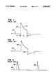
- FIG. 1is a representative monophasic waveform for an implantable cardioverter defibrillator.
- FIG. 2is a schematic circuit diagram illustrating representative prior art circuitry for an implantable cardioverter defibrillator.
- FIG. 3is a representative biphasic waveform for an implantable cardioverter defibrillator.
- FIG. 4is a conceptual multiple short pulse waveform for a defibrillator.
- FIG. 5is a schematic circuit diagram of one embodiment of the implantable cardioverter defibrillator rapid pulse circuitry of this invention.
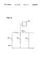
- FIG. 6is a schematic circuit diagram of another embodiment of the implantable cardioverter defibrillator rapid pulse circuitry of this invention.
- FIG. 1illustrates a common waveform utilized by implantable cardioverter defibrillators.
- Waveform 10discloses the monophasic pulse portion 12 exhibited during capacitive discharge.
- Monophasic pulse 12is derived by charging a large capacitor to high voltage and discharging that capacitor into the heart. After a period of time T 1 has elapsed, the current flow is removed which results in the truncated shape 15 of the monophasic pulse 12.
- FIG. 2illustrates representative circuitry for generating a pulse similar to that disclosed in FIG. 1.
- Circuit 18comprises battery 20 which is used to provide a current through the primary winding of transformer 23. The current is cycled on and off at a high rate of speed by switching transistor 25. The output from transformer 23 is rectified by diode 28 and is captured in the main storage capacitor 32.
- silicon controlled rectifier 36is triggered providing a current path from capacitor 23 to the electrodes 40, 41 in the heart.
- silicon controlled rectifier 44is triggered. This quickly discharges capacitor 32 and back biases silicon controlled rectifier 36 to shut off the flow of current through electrodes 40, 41 to the heart.
- the biphasic waveform 50 depicted in FIG. 3is an improvement over the monophasic waveform 10 of FIG. 1.
- Biphasic pulse 52commences with a first phase that is substantially identical to that of monophasic pulse 12. However, at the time of truncation following time period T 1 the current is not merely interrupted but is reversed, producing the configuration shown as pulse section 56. This reversal is commonly done by the use of current reversal means, such as H-bridge circuitry, not shown here.
- Use of a biphasic pulse techniquemay reduce the energy required for each defibrillation pulse by about an average of 25 percent.
- the energy required to defibrillate in each pulseis a critical determinant of the size of an implantable cardioverter defibrillator. This is because the main storage capacitor, such as capacitor 32 shown in FIG. 1, is normally the largest single component in such an ICD device. The most efficient proven capacitors of this type will store about 1.5 Joules per cubic centimeter, and are also the major determinant of the volume of an implantable cardioverter defibrillator. Since this class of defibrillator device is implantable, it is critical that it be made as small as possible. This is particularly important as now ICD devices are designed for pectoral implantation. This directly translates into a severe constraint on the volume of the device and the energy available per defibrillation pulse.
- the multiple pulse defibrillation concept as generally shown in FIG. 4has been experimented with for many years.
- Ventricular defibrillation of dogs with waves comprising two pulses with a pulse length and pulse interval adjusted so that those cells excitable at any moment are defibrillated by the first pulse and are refractory to the second pulsewas disclosed by Kugelberg as early as October 1965, in the Scandinavian Society of Thoracic Surgery, pages 123-128.
- Kugelbergconsidered a variety of pulses and spacings and found that defibrillation was indeed quite possible with multiple pulses.
- Sweeneydiscloses adjusting the timing between multiple bursts of defibrillation energy based upon the fibrillation cycle length of the mammal.
- Sweeney and Reiddisclose that the interaction between multiple pulses is non-linearly related to the fibrillation cycle length, and that the spacing between multiple pulses may be a fixed percentage of the spacing between fibrillation zero crossings in the heart.
- II-610Supplement II Circulation, Vol. 84, No. 4, October 1991, No. 2425
- Johnson et aldisclose that successive biphasic shocks delivered through two different electrodes may be either beneficial or detrimental depending on the delay between the two shocks. (NASPE Abstracts, April 1991, Part II, no.
- the multiple pulse waveform 60 of FIG. 4depicts activation of a representative multiple defibrillator system.
- the systemwould likely lower the total defibrillation threshold by about 50 percent, cutting the 30 Joule accepted limit to about 15 Joules per pulse.
- Such a systemrequires multiple sizeable capacitors.
- the present inventionteaches means for overcoming the impediments of the theoretical multiple pulse systems.
- the inventionalso discloses novel means for providing a rapid pulse power system for use with conventional ICD circuits to permit optional prompt transition from a widely spaced defibrillation pulse sequence to a closely spaced defibrillation pulse sequence.
- the energy generation problemis appreciated more fully by calculating the charging power required of a representative capacitor system in an ICD device. Assuming a conventional single pulse defibrillator which is designed to deliver a 30 Joule pulse, a 10 second delay for capacitor charging is considered acceptable after fibrillation is detected. The charging power is described by simple calculation of 30 Joules divided by 10 seconds, which yields 3 watts. This 3 watt level of power is available from high quality defibrillation primary cells, such as lithium silver vanadium pentoxide cells, although others may be suitable.
- the capacitorcould be designed to store only 15 Joules and could be made of only half the size of present capacitors.
- the capacitorhas 10 seconds to charge in order to create the first pulse 62 by use of present circuitry, the capacitor then must be quickly recharged to provide the second pulse 63.
- the amount of time required to quickly rechargeis the same time as that required for optimum spacing between the two pulses, which is about 0.25 seconds. Therefore, the charging power must be equal to 15 Joules divided by 0.25 seconds. This requires a 60 watt power source.
- there is no functional implantable batterywhich is capable of providing such power output.
- FIG. 5discloses the essential circuit elements of one embodiment of the present invention in which circuit 67 uses both a primary battery and an intermediate power intensifying battery, with the latter comprising a very high power output battery to provide the high charging power between capacitor pulses.
- battery 70is a low amperage primary defibrillation cell, which is preferably a lithium silver vanadium pentoxide type, although other materials are feasible.
- primary defibrillation cellwhich is preferably a lithium silver vanadium pentoxide type, although other materials are feasible.
- battery 70is used to quickly charge a rechargeable battery 73 which is capable of very high power output. This is preferably accomplished through the use of transistor switch 76.
- Battery 73is preferably selected from a list of possible high power rechargeable batteries, such as a lithium titanium disulfide, lithium sulphur dioxide, or others suitable for producing the desired power in a rechargeable configuration. When battery 73 has been sufficiently charged then it is useful as a source of high current charging power to capacitor 32 in circuitry sub-section 82, shown in circuit 18 of FIG. 2 and in circuit 67 of FIG. 5.
- the difference between the capacitor charging circuitry of FIG. 5 and FIG. 2is an approximately 20:1 charging power ratio of 60 watts rather than 3 watts.
- the charging circuitry shown as schematic circuit 67provides power means for recharging the capacitor of the related ICD device, after an initial discharge, between subsequent multiple pulses. This eliminates additional capacitors and eliminates about half of the capacitor volume of known ICD devices. The invention also results in significant improvement in size and operation of an ICD device.
- An alternate embodiment for charging rechargeable battery 73 after fibrillation is detectedcomprises maintaining battery 73 substantially charged at all times. This may be accomplished by a variety of methods, including using primary battery 70 to provide a continuous nominal charge to battery 73, which is a recharging technique similar to that disclosed in co-pending U.S. patent application Ser. No. 07/993,094, filed concurrently on Dec. 18, 1992, and titled Staged Energy Concentration for a Defibrillator.
- circuit 90comprises a relatively low amperage, e.g. milliamps, primary defibrillation battery 93.
- a battery 93comprises a pacing type lithium iodide battery, although other materials are also suitable.
- Circuit 90also comprises high power output (approximately 1-3 amps) intermediate power intensifying battery 97.
- a preferred battery 97comprises a lithium titanium di-sulfide battery.
- Battery 101comprises a very high amperage (10-30 amps) battery. In operation, circuit 90 allows continuous trickle charge from battery 93 to battery 97. This maintains battery 97 in a substantially fully charged configuration until detection of fibrillation.
- battery 97After detection of fibrillation, battery 97 simultaneously charges the main energy delivery capacitor 32 within sub-section 82 and battery 101, via switch 105. Capacitor 32 then discharges and is again re-charged with battery 97. However, battery 97 is not normally able to fully charge capacitor 32 in less than at least about 5 seconds. In a closely spaced multiple pulse ICD device power system it is necessary to provide means other than battery 97 to provide charging power for subsequent pulses to the heart. Rather than providing multiple charging pathways or a plurality of capacitors, circuit 90 discloses use of battery 101 to provide high amperage high power means for charging a main energy delivery capacitor for countershock pulses after the initial countershock/pulse.
- the inventionalso comprises a method for configuring an implantable cardioverter defibrillator main energy delivery electrical circuit for delivery of multiple closely spaced defibrillation pulses to a heart.
- the methodcomprises the steps of providing a low power output primary defibrillator battery, and arranging a high power output intermediate power intensifying battery with switch means for permitting the intermediate power intensifying battery to be rechargeable from the primary defibrillator battery and to selectively rapidly charge a main energy delivery capacitor.
- a main energy delivery capacitoris electrically configured for discharging, in a first pulse, electrical current derived from the primary defibrillator battery and for discharging certain subsequent pulses of electrical current derived from the intermediate power intensifying battery so that the circuit permits the implantable cardioverter defibrillator device to deliver multiple closely spaced defibrillation pulses to a heart using a single capacitor.
- a further stepcomprises simultaneously charging both the high power output intermediate power intensifying battery and the main energy delivery capacitor using the low power output primary defibrillator battery.
- circuits 67 and 90are each also advantageous as a rapid pulse power system for use with implantable cardioverter devices.
- This rapid pulse power systemmay be integrated into other known or proprietary circuits as a means of enabling rapid and optional transition from a widely spaced defibrillation pulse sequence to a closely spaced defibrillation pulse sequence. This is accomplished without adding any additional capacitors, which would detract from the size and volume advantages of the invention.
- the inventionalso discloses a method of configuring an implantable cardioverter defibrillator electrical circuit as a rapid pulse power system to enable rapid transition from a widely spaced defibrillation pulse sequence to a closely spaced defibrillation pulse sequence.
- the methodcomprises the steps of providing a low power output primary defibrillator battery, arranging a high power output intermediate power intensifying battery, providing switch means for permitting the intermediate power intensifying battery to rapidly charge a main energy delivery capacitor, responding to a remote signal and selectively discharging a main energy delivery capacitor.
- the main energy delivery capacitoris discharged, in a first pulse, with an electrical charge derived from the primary defibrillator battery and, in certain subsequent multiple closely spaced defibrillation pulses, with electrical charge derived from the intermediate power intensifying battery.
- the pulsesare deliverable to a heart at any time interval following an initial defibrillation attempt using another defibrillator pulse power source.
Landscapes
- Health & Medical Sciences (AREA)
- Cardiology (AREA)
- Heart & Thoracic Surgery (AREA)
- Engineering & Computer Science (AREA)
- Biomedical Technology (AREA)
- Nuclear Medicine, Radiotherapy & Molecular Imaging (AREA)
- Radiology & Medical Imaging (AREA)
- Life Sciences & Earth Sciences (AREA)
- Animal Behavior & Ethology (AREA)
- General Health & Medical Sciences (AREA)
- Public Health (AREA)
- Veterinary Medicine (AREA)
- Electrotherapy Devices (AREA)
Abstract
Description
Claims (27)
Priority Applications (6)
| Application Number | Priority Date | Filing Date | Title |
|---|---|---|---|
| US07/993,292US5383907A (en) | 1992-12-18 | 1992-12-18 | System and method for delivering multiple closely spaced defibrillation pulses |
| US08/263,257US5405363A (en) | 1991-03-15 | 1994-06-21 | Implantable cardioverter defibrillator having a smaller displacement volume |
| US08/344,281US5522853A (en) | 1992-10-27 | 1994-11-21 | Method and apparatus for progressive recruitment of cardiac fibrillation |
| US08/376,353US5620464A (en) | 1992-12-18 | 1995-01-23 | System and method for delivering multiple closely spaced defibrillation pulses |
| US08/412,920US5827326A (en) | 1991-03-15 | 1995-03-29 | Implantable cardioverter defibrillator having a smaller energy storage capacity |
| US08/745,724US5836973A (en) | 1992-12-18 | 1996-11-12 | Staged energy concentration for an implantable biomedical device |
Applications Claiming Priority (1)
| Application Number | Priority Date | Filing Date | Title |
|---|---|---|---|
| US07/993,292US5383907A (en) | 1992-12-18 | 1992-12-18 | System and method for delivering multiple closely spaced defibrillation pulses |
Related Child Applications (4)
| Application Number | Title | Priority Date | Filing Date |
|---|---|---|---|
| US08/263,257Continuation-In-PartUS5405363A (en) | 1991-03-15 | 1994-06-21 | Implantable cardioverter defibrillator having a smaller displacement volume |
| US08/344,281Continuation-In-PartUS5522853A (en) | 1992-10-27 | 1994-11-21 | Method and apparatus for progressive recruitment of cardiac fibrillation |
| US08/376,353Continuation-In-PartUS5620464A (en) | 1992-12-18 | 1995-01-23 | System and method for delivering multiple closely spaced defibrillation pulses |
| US08/412,920Continuation-In-PartUS5827326A (en) | 1991-03-15 | 1995-03-29 | Implantable cardioverter defibrillator having a smaller energy storage capacity |
Publications (1)
| Publication Number | Publication Date |
|---|---|
| US5383907Atrue US5383907A (en) | 1995-01-24 |
Family
ID=25539353
Family Applications (1)
| Application Number | Title | Priority Date | Filing Date |
|---|---|---|---|
| US07/993,292Expired - Fee RelatedUS5383907A (en) | 1991-03-15 | 1992-12-18 | System and method for delivering multiple closely spaced defibrillation pulses |
Country Status (1)
| Country | Link |
|---|---|
| US (1) | US5383907A (en) |
Cited By (38)
| Publication number | Priority date | Publication date | Assignee | Title |
|---|---|---|---|---|
| WO1996022811A1 (en)* | 1995-01-23 | 1996-08-01 | Angeion Corporation | Staged energy storage system for implantable cardioverter-defibrillator |
| US5620464A (en)* | 1992-12-18 | 1997-04-15 | Angeion Corporation | System and method for delivering multiple closely spaced defibrillation pulses |
| US5674248A (en)* | 1995-01-23 | 1997-10-07 | Angeion Corporation | Staged energy concentration for an implantable biomedical device |
| US5919211A (en)* | 1996-06-27 | 1999-07-06 | Adams; Theodore P. | ICD power source using multiple single use batteries |
| US6093982A (en)* | 1996-11-15 | 2000-07-25 | Kroll; Mark W. | High voltage output array switching system |
| US20030069625A1 (en)* | 1998-07-22 | 2003-04-10 | Ley Gregory R. | Lead with terminal connector assembly |
| US6567698B2 (en) | 2001-07-17 | 2003-05-20 | Koninklijke Philips Electronics N.V. | System and method for applying sequential low energy defibrillation pulses |
| US20040147972A1 (en)* | 2003-01-24 | 2004-07-29 | Wilson Greatbatch | Hybrid battery power source for implantable medical use |
| US20040147971A1 (en)* | 2003-01-24 | 2004-07-29 | Wilson Greatbatch | Hybrid battery power source for implantable medical use |
| US20040158296A1 (en)* | 2003-01-24 | 2004-08-12 | Wilson Greatbatch | Hybrid battery power source for implantable medical use |
| US20040193227A1 (en)* | 2003-03-31 | 2004-09-30 | Schmidt Craig L. | High power implantable battery with improved safety and method of manufacture |
| US20040249431A1 (en)* | 2003-06-04 | 2004-12-09 | Terrance Ransbury | Device and method for retaining a medical device within a vessel |
| US20040249417A1 (en)* | 2003-06-04 | 2004-12-09 | Terrance Ransbury | Implantable intravascular device for defibrillation and/or pacing |
| US6847842B1 (en) | 2000-05-15 | 2005-01-25 | Cardiac Pacemakers, Inc. | Method and apparatus for reducing early recurrence of atrial fibrillation with defibrillation shock therapy |
| US6915169B2 (en) | 1998-07-22 | 2005-07-05 | Cardiac Pacemakers, Inc. | Extendable and retractable lead having a snap-fit terminal connector |
| US20050154437A1 (en)* | 2003-12-12 | 2005-07-14 | Williams Michael S. | Implantable medical device having pre-implant exoskeleton |
| USRE38777E1 (en)* | 1992-07-16 | 2005-08-16 | Angeion Corp. | Dual battery power system for an implantable cardioverter defibrillator with voltage booster |
| US20050228471A1 (en)* | 2003-06-04 | 2005-10-13 | Williams Michael S | Method and apparatus for retaining medical implants within body vessels |
| US20050234431A1 (en)* | 2004-02-10 | 2005-10-20 | Williams Michael S | Intravascular delivery system for therapeutic agents |
| WO2006052838A2 (en) | 2004-11-04 | 2006-05-18 | Washington University Of St. Louis | Method for low-voltage termination of cardiac arrhythmias by effectively unpinning anatomical reentries |
| US20080077219A1 (en)* | 2003-06-04 | 2008-03-27 | Williams Michael S | Intravascular electrophysiological system and methods |
| US20080223381A1 (en)* | 2003-03-31 | 2008-09-18 | Schmidt Craig L | High power implantable battery with improved safety and method of manufacture |
| US20090204164A1 (en)* | 2007-12-11 | 2009-08-13 | Efimov Igor R | Method and device for low-energy termination of atrial tachyarrhythmias |
| WO2011139596A2 (en) | 2010-05-07 | 2011-11-10 | The Washington University | Method and device for three-stage atrial cardioversion therapy |
| CN101447745B (en)* | 2007-09-11 | 2012-03-21 | 通用汽车环球科技运作公司 | Two-source series inverter |
| US8391995B2 (en) | 2006-11-13 | 2013-03-05 | The Washington University | Cardiac pacing using the inferior nodal extension |
| US8473051B1 (en) | 2010-12-29 | 2013-06-25 | Cardialen, Inc. | Low-energy atrial cardioversion therapy with controllable pulse-shaped waveforms |
| US8874208B2 (en) | 2007-12-11 | 2014-10-28 | The Washington University | Methods and devices for three-stage ventricular therapy |
| US9539435B2 (en) | 2014-09-08 | 2017-01-10 | Medtronic, Inc. | Transthoracic protection circuit for implantable medical devices |
| US9579517B2 (en) | 2014-09-08 | 2017-02-28 | Medtronic, Inc. | Transformer-based charging circuits for implantable medical devices |
| US9604071B2 (en) | 2014-09-08 | 2017-03-28 | Medtronic, Inc. | Implantable medical devices having multi-cell power sources |
| US9636504B2 (en) | 2012-12-11 | 2017-05-02 | Galvani, Ltd. | Arrhythmia electrotheraphy device and method with provisions for mitigating patient discomfort |
| US9643025B2 (en) | 2014-09-08 | 2017-05-09 | Medtronic, Inc. | Multi-primary transformer charging circuits for implantable medical devices |
| US9724528B2 (en) | 2014-09-08 | 2017-08-08 | Medtronic, Inc. | Multiple transformer charging circuits for implantable medical devices |
| US9861828B2 (en) | 2014-09-08 | 2018-01-09 | Medtronic, Inc. | Monitoring multi-cell power source of an implantable medical device |
| US9861827B2 (en) | 2014-09-08 | 2018-01-09 | Medtronic, Inc. | Implantable medical devices having multi-cell power sources |
| US20180227849A1 (en)* | 2017-02-06 | 2018-08-09 | Itron Networked Solutions, Inc. | Battery control for safeguarding lower voltage integrated circuits |
| US10905884B2 (en) | 2012-07-20 | 2021-02-02 | Cardialen, Inc. | Multi-stage atrial cardioversion therapy leads |
Citations (5)
| Publication number | Priority date | Publication date | Assignee | Title |
|---|---|---|---|---|
| US3211154A (en)* | 1962-06-25 | 1965-10-12 | Mine Safety Appliances Co | Sequence switch for ventricular defibrillator |
| US4025860A (en)* | 1974-09-14 | 1977-05-24 | Agency Of Industrial Science & Technology | Control system for battery hybrid system |
| US4530550A (en)* | 1982-09-13 | 1985-07-23 | Olympus Optical Company Ltd. | Power supply unit for electronic flash |
| US4637397A (en)* | 1985-05-30 | 1987-01-20 | Case Western Reserve University | Triphasic wave defibrillation |
| US4931947A (en)* | 1983-09-29 | 1990-06-05 | Engelhard Corporation | Fuel cell/battery hybrid system having battery charge-level control |
- 1992
- 1992-12-18USUS07/993,292patent/US5383907A/ennot_activeExpired - Fee Related
Patent Citations (5)
| Publication number | Priority date | Publication date | Assignee | Title |
|---|---|---|---|---|
| US3211154A (en)* | 1962-06-25 | 1965-10-12 | Mine Safety Appliances Co | Sequence switch for ventricular defibrillator |
| US4025860A (en)* | 1974-09-14 | 1977-05-24 | Agency Of Industrial Science & Technology | Control system for battery hybrid system |
| US4530550A (en)* | 1982-09-13 | 1985-07-23 | Olympus Optical Company Ltd. | Power supply unit for electronic flash |
| US4931947A (en)* | 1983-09-29 | 1990-06-05 | Engelhard Corporation | Fuel cell/battery hybrid system having battery charge-level control |
| US4637397A (en)* | 1985-05-30 | 1987-01-20 | Case Western Reserve University | Triphasic wave defibrillation |
Cited By (84)
| Publication number | Priority date | Publication date | Assignee | Title |
|---|---|---|---|---|
| USRE38777E1 (en)* | 1992-07-16 | 2005-08-16 | Angeion Corp. | Dual battery power system for an implantable cardioverter defibrillator with voltage booster |
| US5620464A (en)* | 1992-12-18 | 1997-04-15 | Angeion Corporation | System and method for delivering multiple closely spaced defibrillation pulses |
| WO1996022811A1 (en)* | 1995-01-23 | 1996-08-01 | Angeion Corporation | Staged energy storage system for implantable cardioverter-defibrillator |
| US5674248A (en)* | 1995-01-23 | 1997-10-07 | Angeion Corporation | Staged energy concentration for an implantable biomedical device |
| US5919211A (en)* | 1996-06-27 | 1999-07-06 | Adams; Theodore P. | ICD power source using multiple single use batteries |
| US6093982A (en)* | 1996-11-15 | 2000-07-25 | Kroll; Mark W. | High voltage output array switching system |
| US7392095B2 (en) | 1998-07-22 | 2008-06-24 | Cardiac Pacemakers, Inc. | Extendable and retractable lead having a snap-fit terminal connector |
| US20060089698A1 (en)* | 1998-07-22 | 2006-04-27 | Cardiac Pacemakers, Inc. | Lead with terminal connector assembly |
| US6983185B2 (en) | 1998-07-22 | 2006-01-03 | Cardiac Pacemakers, Inc. | Lead with terminal connector assembly |
| US7774934B2 (en) | 1998-07-22 | 2010-08-17 | Cardiac Pacemakers, Inc. | Method for making a terminal connector |
| US6915169B2 (en) | 1998-07-22 | 2005-07-05 | Cardiac Pacemakers, Inc. | Extendable and retractable lead having a snap-fit terminal connector |
| US20030069625A1 (en)* | 1998-07-22 | 2003-04-10 | Ley Gregory R. | Lead with terminal connector assembly |
| US8285398B2 (en) | 1998-07-22 | 2012-10-09 | Cardiac Pacemakers, Inc. | Lead with terminal connector assembly |
| US8209035B2 (en) | 1998-07-22 | 2012-06-26 | Cardiac Pacemakers, Inc. | Extendable and retractable lead having a snap-fit terminal connector |
| US6847842B1 (en) | 2000-05-15 | 2005-01-25 | Cardiac Pacemakers, Inc. | Method and apparatus for reducing early recurrence of atrial fibrillation with defibrillation shock therapy |
| US6567698B2 (en) | 2001-07-17 | 2003-05-20 | Koninklijke Philips Electronics N.V. | System and method for applying sequential low energy defibrillation pulses |
| US20040147971A1 (en)* | 2003-01-24 | 2004-07-29 | Wilson Greatbatch | Hybrid battery power source for implantable medical use |
| US20040225333A1 (en)* | 2003-01-24 | 2004-11-11 | Wilson Greatbatch | Hybrid battery power source for implantable medical use |
| US20040158296A1 (en)* | 2003-01-24 | 2004-08-12 | Wilson Greatbatch | Hybrid battery power source for implantable medical use |
| US6909915B2 (en) | 2003-01-24 | 2005-06-21 | Gentcorp Ltd. | Hybrid battery power source for implantable medical use |
| US7020519B2 (en) | 2003-01-24 | 2006-03-28 | Gentcorp Ltd | Hybrid battery power source for implantable medical use |
| US20040147972A1 (en)* | 2003-01-24 | 2004-07-29 | Wilson Greatbatch | Hybrid battery power source for implantable medical use |
| US7079893B2 (en) | 2003-01-24 | 2006-07-18 | Gentcorp Ltd. | Hybrid battery power source for implantable medical use |
| US7136701B2 (en) | 2003-01-24 | 2006-11-14 | Gentcorp Ltd. | Hybrid battery power source for implantable medical use |
| US8027728B2 (en) | 2003-03-31 | 2011-09-27 | Medtronic, Inc. | High power implantable battery with improved safety and method of manufacture |
| US20040193227A1 (en)* | 2003-03-31 | 2004-09-30 | Schmidt Craig L. | High power implantable battery with improved safety and method of manufacture |
| US20080223381A1 (en)* | 2003-03-31 | 2008-09-18 | Schmidt Craig L | High power implantable battery with improved safety and method of manufacture |
| US7209784B2 (en) | 2003-03-31 | 2007-04-24 | Medtronic, Inc. | High power implantable battery with improved safety and method of manufacture |
| US7840282B2 (en) | 2003-06-04 | 2010-11-23 | Synecor Llc | Method and apparatus for retaining medical implants within body vessels |
| US20040249417A1 (en)* | 2003-06-04 | 2004-12-09 | Terrance Ransbury | Implantable intravascular device for defibrillation and/or pacing |
| US20080077219A1 (en)* | 2003-06-04 | 2008-03-27 | Williams Michael S | Intravascular electrophysiological system and methods |
| US20040249431A1 (en)* | 2003-06-04 | 2004-12-09 | Terrance Ransbury | Device and method for retaining a medical device within a vessel |
| US8239045B2 (en) | 2003-06-04 | 2012-08-07 | Synecor Llc | Device and method for retaining a medical device within a vessel |
| US7082336B2 (en) | 2003-06-04 | 2006-07-25 | Synecor, Llc | Implantable intravascular device for defibrillation and/or pacing |
| US7529589B2 (en) | 2003-06-04 | 2009-05-05 | Synecor Llc | Intravascular electrophysiological system and methods |
| US7899554B2 (en) | 2003-06-04 | 2011-03-01 | Synecor Llc | Intravascular System and Method |
| US7617007B2 (en) | 2003-06-04 | 2009-11-10 | Synecor Llc | Method and apparatus for retaining medical implants within body vessels |
| US20090281521A1 (en)* | 2003-06-04 | 2009-11-12 | Williams Michael S | Method and apparatus for retaining medical implants within body vessels |
| US7734343B2 (en) | 2003-06-04 | 2010-06-08 | Synecor, Llc | Implantable intravascular device for defibrillation and/or pacing |
| US20050228471A1 (en)* | 2003-06-04 | 2005-10-13 | Williams Michael S | Method and apparatus for retaining medical implants within body vessels |
| US7747335B2 (en) | 2003-12-12 | 2010-06-29 | Synecor Llc | Implantable medical device having pre-implant exoskeleton |
| US20050154437A1 (en)* | 2003-12-12 | 2005-07-14 | Williams Michael S. | Implantable medical device having pre-implant exoskeleton |
| US20050234431A1 (en)* | 2004-02-10 | 2005-10-20 | Williams Michael S | Intravascular delivery system for therapeutic agents |
| US20090048583A1 (en)* | 2004-02-10 | 2009-02-19 | Williams Michael S | Intravascular delivery system for therapeutic agents |
| US8175702B2 (en) | 2004-11-04 | 2012-05-08 | The Washington University | Method for low-voltage termination of cardiac arrhythmias by effectively unpinning anatomical reentries |
| US10549108B2 (en) | 2004-11-04 | 2020-02-04 | The Washington University | Method for low-voltage termination of cardiac arrhythmias by effectively unpinning anatomical reentries |
| US11191474B2 (en) | 2004-11-04 | 2021-12-07 | Washington University | Method for low-voltage termination of cardiac arrhythmias by effectively unpinning anatomical reentries |
| WO2006052838A2 (en) | 2004-11-04 | 2006-05-18 | Washington University Of St. Louis | Method for low-voltage termination of cardiac arrhythmias by effectively unpinning anatomical reentries |
| US20060161206A1 (en)* | 2004-11-04 | 2006-07-20 | Efimov Igor R | Method for low-voltage termination of cardiac arrhythmias by effectively unpinning anatomical reentries |
| US10071257B2 (en) | 2004-11-04 | 2018-09-11 | Washington University | Method for low-voltage termination of cardiac arrhythmias by effectively unpinning anatomical reentries |
| US9586055B2 (en) | 2004-11-04 | 2017-03-07 | Washington University | Method for low-voltage termination of cardiac arrhythmias by effectively unpinning anatomical reentries |
| US9067079B2 (en) | 2004-11-04 | 2015-06-30 | Washington University | Method for low-voltage termination of cardiac arrhythmias by effectively unpinning anatomical reentries |
| US8639325B2 (en) | 2004-11-04 | 2014-01-28 | Washington University | Method for low-voltage termination of cardiac arrhythmias by effectively unpinning anatomical reentries |
| US8391995B2 (en) | 2006-11-13 | 2013-03-05 | The Washington University | Cardiac pacing using the inferior nodal extension |
| CN101447745B (en)* | 2007-09-11 | 2012-03-21 | 通用汽车环球科技运作公司 | Two-source series inverter |
| US8706216B2 (en) | 2007-12-11 | 2014-04-22 | The Washington University | Method and device for three-stage atrial cardioversion therapy |
| US8509889B2 (en) | 2007-12-11 | 2013-08-13 | Washington University | Method and device for low-energy termination of atrial tachyarrhythmias |
| US8560066B2 (en) | 2007-12-11 | 2013-10-15 | Washington University | Method and device for three-stage atrial cardioversion therapy |
| US9289620B2 (en) | 2007-12-11 | 2016-03-22 | The Washington University | Method and device for three-stage atrial cardioversion therapy |
| US9526907B2 (en) | 2007-12-11 | 2016-12-27 | Washington University | Methods and devices for multi-stage ventricular therapy |
| US10099062B2 (en) | 2007-12-11 | 2018-10-16 | Washington University | Methods and devices for multi-stage ventricular therapy |
| US20090204164A1 (en)* | 2007-12-11 | 2009-08-13 | Efimov Igor R | Method and device for low-energy termination of atrial tachyarrhythmias |
| US10441805B2 (en) | 2007-12-11 | 2019-10-15 | The Washington University | Method and device for three-stage atrial cardioversion therapy |
| US8874208B2 (en) | 2007-12-11 | 2014-10-28 | The Washington University | Methods and devices for three-stage ventricular therapy |
| US9814895B2 (en) | 2007-12-11 | 2017-11-14 | The Washington University | Method and device for three-stage atrial cardioversion therapy |
| US11097120B2 (en) | 2007-12-11 | 2021-08-24 | The Washington University | Method and device for atrial cardioversion therapy |
| US11083905B2 (en) | 2007-12-11 | 2021-08-10 | The Washington University | Methods and devices for ventricular therapy |
| US10413741B2 (en) | 2007-12-11 | 2019-09-17 | The Washington University | Methods and devices for multi-stage ventricular therapy |
| WO2011139596A2 (en) | 2010-05-07 | 2011-11-10 | The Washington University | Method and device for three-stage atrial cardioversion therapy |
| US8473051B1 (en) | 2010-12-29 | 2013-06-25 | Cardialen, Inc. | Low-energy atrial cardioversion therapy with controllable pulse-shaped waveforms |
| US11918816B2 (en) | 2012-07-20 | 2024-03-05 | Maxwell Biomedical Inc. | Multi-stage atrial cardioversion therapy leads |
| US10905884B2 (en) | 2012-07-20 | 2021-02-02 | Cardialen, Inc. | Multi-stage atrial cardioversion therapy leads |
| US9636504B2 (en) | 2012-12-11 | 2017-05-02 | Galvani, Ltd. | Arrhythmia electrotheraphy device and method with provisions for mitigating patient discomfort |
| US10143851B2 (en) | 2012-12-11 | 2018-12-04 | Galvani, Ltd. | Arrhythmia electrotherapy device and method with provisions for mitigating patient discomfort |
| US9604071B2 (en) | 2014-09-08 | 2017-03-28 | Medtronic, Inc. | Implantable medical devices having multi-cell power sources |
| US9861827B2 (en) | 2014-09-08 | 2018-01-09 | Medtronic, Inc. | Implantable medical devices having multi-cell power sources |
| US9861828B2 (en) | 2014-09-08 | 2018-01-09 | Medtronic, Inc. | Monitoring multi-cell power source of an implantable medical device |
| US9750950B2 (en) | 2014-09-08 | 2017-09-05 | Medtronic, Inc. | Implantable medical device having isolated multi-cell power sources |
| US9724528B2 (en) | 2014-09-08 | 2017-08-08 | Medtronic, Inc. | Multiple transformer charging circuits for implantable medical devices |
| US9643025B2 (en) | 2014-09-08 | 2017-05-09 | Medtronic, Inc. | Multi-primary transformer charging circuits for implantable medical devices |
| US9579517B2 (en) | 2014-09-08 | 2017-02-28 | Medtronic, Inc. | Transformer-based charging circuits for implantable medical devices |
| US9539435B2 (en) | 2014-09-08 | 2017-01-10 | Medtronic, Inc. | Transthoracic protection circuit for implantable medical devices |
| US20180227849A1 (en)* | 2017-02-06 | 2018-08-09 | Itron Networked Solutions, Inc. | Battery control for safeguarding lower voltage integrated circuits |
| US11153819B2 (en)* | 2017-02-06 | 2021-10-19 | Itron Networked Solutions, Inc. | Battery control for safeguarding lower voltage integrated circuits |
Similar Documents
| Publication | Publication Date | Title |
|---|---|---|
| US5383907A (en) | System and method for delivering multiple closely spaced defibrillation pulses | |
| US5620464A (en) | System and method for delivering multiple closely spaced defibrillation pulses | |
| US5265588A (en) | VCO driven flyback converter for implantable cardoverter/defibrillator | |
| US5405363A (en) | Implantable cardioverter defibrillator having a smaller displacement volume | |
| US5407444A (en) | Staged energy concentration for a defibrillator | |
| US5697953A (en) | Implantable cardioverter defibrillator having a smaller displacement volume | |
| US5957956A (en) | Implantable cardioverter defibrillator having a smaller mass | |
| US5385575A (en) | Implantable cardioverter defibrillator having variable output capacitance | |
| US5836973A (en) | Staged energy concentration for an implantable biomedical device | |
| US5674248A (en) | Staged energy concentration for an implantable biomedical device | |
| US5507781A (en) | Implantable defibrillator system with capacitor switching circuitry | |
| US5391186A (en) | Method and apparatus for utilizing short tau capacitors in an implantable cardioverter defibrillator | |
| US5235979A (en) | Dual battery system for implantable defibrillator | |
| EP0515059B1 (en) | Implantable defibrillator system | |
| US20030216786A1 (en) | Circuit for producing an arbitrary defibrillation waveform | |
| US5314448A (en) | Process for defibrillation pretreatment of a heart | |
| US4595009A (en) | Protection circuit for implantable cardioverter | |
| US6233483B1 (en) | System and method for generating a high efficiency biphasic defibrillation waveform for use in an implantable cardioverter/defibrillator (ICD). | |
| US4548209A (en) | Energy converter for implantable cardioverter | |
| EP0808639B1 (en) | Patient-worn energy delivery apparatus | |
| CA1321622C (en) | Biphasic waveforms for defibrillation | |
| US5591212A (en) | Hybrid battery for implantable pulse generator | |
| US6047212A (en) | External defibrillator capable of delivering patient impedance compensated biphasic waveforms | |
| US5411525A (en) | Dual capacitor biphasic defibrillator waveform generator employing selective connection of capacitors for each phase | |
| US20060195148A1 (en) | Apparatus and method for optimizing capacitor charge in a medical device |
Legal Events
| Date | Code | Title | Description |
|---|---|---|---|
| AS | Assignment | Owner name:ANGEION CORPORATION, MINNESOTA Free format text:ASSIGNMENT OF ASSIGNORS INTEREST.;ASSIGNOR:ANGEMED, INC.;REEL/FRAME:006451/0596 Effective date:19930204 | |
| AS | Assignment | Owner name:ANGEION CORPORATION, MINNESOTA Free format text:ASSIGNMENT OF ASSIGNORS INTEREST.;ASSIGNOR:KROLL, MARK W.;REEL/FRAME:006430/0360 Effective date:19930222 | |
| AS | Assignment | Owner name:GLEN TAYLOR; HANROW BUSINESS FINANCE, INC.; LYLE Free format text:SECURITY INTEREST;ASSIGNOR:ANGEION CORPORATION;REEL/FRAME:007034/0103 Effective date:19940608 | |
| FPAY | Fee payment | Year of fee payment:4 | |
| AS | Assignment | Owner name:NORWEST BUSINESS CREDIT, INC., MINNESOTA Free format text:SECURITY INTEREST;ASSIGNOR:ANGEION CORPORATION;REEL/FRAME:009693/0097 Effective date:19990118 | |
| AS | Assignment | Owner name:ANGEION CORPORATION, MINNESOTA Free format text:RELEASE OF SECURITY INTEREST;ASSIGNOR:NORWEST BUSINESS CREDIT, INC. (N/K/A WELLS FARGO BUSINESS CREDIT, INC.);REEL/FRAME:010470/0293 Effective date:19991202 | |
| REMI | Maintenance fee reminder mailed | ||
| LAPS | Lapse for failure to pay maintenance fees | ||
| LAPS | Lapse for failure to pay maintenance fees | Free format text:PATENT EXPIRED FOR FAILURE TO PAY MAINTENANCE FEES (ORIGINAL EVENT CODE: EXP.); ENTITY STATUS OF PATENT OWNER: LARGE ENTITY | |
| STCH | Information on status: patent discontinuation | Free format text:PATENT EXPIRED DUE TO NONPAYMENT OF MAINTENANCE FEES UNDER 37 CFR 1.362 | |
| FP | Lapsed due to failure to pay maintenance fee | Effective date:20030124 |