US5383792A - Insertable latch means for use in an electrical connector - Google Patents
Insertable latch means for use in an electrical connectorDownload PDFInfo
- Publication number
- US5383792A US5383792AUS08/026,280US2628093AUS5383792AUS 5383792 AUS5383792 AUS 5383792AUS 2628093 AUS2628093 AUS 2628093AUS 5383792 AUS5383792 AUS 5383792A
- Authority
- US
- United States
- Prior art keywords
- card
- daughter card
- latch
- electrical connector
- recited
- Prior art date
- Legal status (The legal status is an assumption and is not a legal conclusion. Google has not performed a legal analysis and makes no representation as to the accuracy of the status listed.)
- Expired - Lifetime
Links
Images


Classifications
- H—ELECTRICITY
- H01—ELECTRIC ELEMENTS
- H01R—ELECTRICALLY-CONDUCTIVE CONNECTIONS; STRUCTURAL ASSOCIATIONS OF A PLURALITY OF MUTUALLY-INSULATED ELECTRICAL CONNECTING ELEMENTS; COUPLING DEVICES; CURRENT COLLECTORS
- H01R12/00—Structural associations of a plurality of mutually-insulated electrical connecting elements, specially adapted for printed circuits, e.g. printed circuit boards [PCB], flat or ribbon cables, or like generally planar structures, e.g. terminal strips, terminal blocks; Coupling devices specially adapted for printed circuits, flat or ribbon cables, or like generally planar structures; Terminals specially adapted for contact with, or insertion into, printed circuits, flat or ribbon cables, or like generally planar structures
- H01R12/70—Coupling devices
- H01R12/7005—Guiding, mounting, polarizing or locking means; Extractors
- H—ELECTRICITY
- H01—ELECTRIC ELEMENTS
- H01R—ELECTRICALLY-CONDUCTIVE CONNECTIONS; STRUCTURAL ASSOCIATIONS OF A PLURALITY OF MUTUALLY-INSULATED ELECTRICAL CONNECTING ELEMENTS; COUPLING DEVICES; CURRENT COLLECTORS
- H01R12/00—Structural associations of a plurality of mutually-insulated electrical connecting elements, specially adapted for printed circuits, e.g. printed circuit boards [PCB], flat or ribbon cables, or like generally planar structures, e.g. terminal strips, terminal blocks; Coupling devices specially adapted for printed circuits, flat or ribbon cables, or like generally planar structures; Terminals specially adapted for contact with, or insertion into, printed circuits, flat or ribbon cables, or like generally planar structures
- H01R12/70—Coupling devices
- H01R12/71—Coupling devices for rigid printing circuits or like structures
Definitions
- the inventionis directed to a latch means for use in an electrical connector.
- the latch meansare insertable into a housing of the connector to cooperate with respective circuit boards, the latch means being configured to accommodate the wide tolerance range associated with the circuit boards.
- the connectorhas contacts positioned therein which extend from a first mating surface of the connector to a second mating surface.
- the contactshave posts which extend from the connector and make electrical engagement with the contact areas of the mother board.
- the daughter boardis then inserted into the connector and rotated to its operating position. As this rotation occurs, contact projections of the contacts engage the contact surfaces of the daughter board.
- latch armsbe provided to cooperate and maintain the daughter board in the operational position.
- the latch membersare provided at the ends of the connector, and are integrally molded with the housing.
- the configuration of the latch membersprovides the latch members with the resilient characteristics required in order to allow the latch members to cooperate with the daughter board to maintain the daughter board in electrical engagement with the terminals of the connector.
- latch membersare molded from plastic material, and as the resilient characteristics of plastic is not significant, the latch members are likely to take a permanent set, particularly when the connector is used over many cycles. This likelihood is increased due to the fact that the latch members must have a relatively thin width when molded. This requirement reduces the durability of the latch members, so that the latch members are only strong enough to support approximately 25 cycles (insertions and removals of the printed circuit board). Consequently, if the electrical connector is to be used over many cycles, the risk of failure of the electrical connector is greatly increased.
- the latch memberscould be made from a material having the desired resilient characteristics. This requires the latch members to be separately manufactured and inserted into the housing after the housing has been molded.
- the postcould be strengthened without the need to increase the area which the post occupies.
- the utilization of this type of postwould require the post to be attached to the connector in some manner, as the post would no longer be able to be molded at the same time as the housing of the connector.
- the inventionis directed to an electrical connector which has an improved latch member provided at each end thereof.
- One embodiment of the latch memberhas an integral mounting post which extends beyond the connector to cooperate with the mother board.
- the latch membersare constructed from a material which has the resilient and strength characteristics required to insure for effective operation over many cycles. It is also possible to provide the latch members with adequate electrical properties, so that the latch members may be used to supply power from the mother board to the daughter board.
- An insertable latch memberfor use in an electrical connector.
- the electrical connectorhas a housing with a first major surface and an oppositely facing second major surface.
- a daughter or baby board receiving recess or slotextends from the first major surface toward the second major surface.
- Contact terminalsare provided adjacent to the baby board receiving recess and extend from the baby board receiving recess to beyond the second major surface.
- Latch receiving recessesare provided adjacent to the baby board receiving recess, and are dimensioned to receive the latch member therein.
- One embodiment of the latch memberhas a resilient section and mounting section which is integrally attached to the resilient section.
- the resilient sectionhas a resilient arm which extends from a base portion of the resilient section. A free end of the resilient arm is formed to provide a projection which extends in a direction which is essentially perpendicular to the longitudinal axis of the resilient arm.
- the mounting sectionextends from the base portion of the resilient section, and is dimensioned to be received in an aperture of a printed circuit board. The resilient section and the mounting section form an electrically conductive pathway across which electrical signals are conducted.
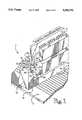
- FIG. 1is a perspective view of a connector with an insertable latch member provided therein, the connector electrically connects a mother board with a daughter card.
- FIG. 2is a perspective view of the connector, showing the cooperation of the latch member with the daughter card.
- FIG. 3is a cross-sectional view of an end portion of the connector, showing the latch member provided in a latch receiving recesses, the motion of the latch member as the daughter card is inserted into the connector is indicated by the lines shown in phantom.
- FIG. 4is a perspective view of the latch member removed from the latch receiving recess of the connector.
- FIG. 5 and 6are perspective views of the latch member removed from the latch receiving recess, these views differ from FIG. 4 only in the angle at which the latch member is viewed.
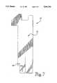
- FIG. 7is a plan view of a sheet metal blank from which the latch member is formed.
- FIGS. 1 and 2there is illustrated a low insertion force electrical connector 2.
- the connectorelectrically and mechanically connects printed circuit board 4 to printed circuit board 6.
- the connector 2has an elongated housing 8 having a plurality of contact receiving cavities 10 located in an elongated base 12.
- the housingis made from any material having the desired dielectric characteristics.
- the plurality of contact receiving cavities 10extend from top surface 14 of base 12 to proximate bottom surface 16 of the base.
- the cavitiesare provided in spaced apart parallel relationship to each other and to ends 18 of base 8.
- the cavitiesare in communication with a board-receiving opening 20.
- the exact shape of the cavities 10varies according to the shape of contacts 22 to be secured therein.
- Contacts 22are disposed in cavities 10. Each contact is made from sheet metal stock having the desired conductive and resilient characteristics. A more detailed explanation of a particular type of contact which can be used in the connector is more fully disclosed in U.S. Pat. No. 4,737,120, which is hereby incorporated by reference.
- each latch receiving recess 24is provided proximate the board-receiving opening 20.
- each latch receiving recess 24has three side walls 26 which extend from an upper surface 28 of the connector housing toward the bottom surface 16 of the base.
- a recess 32is provided in one of the side walls 26, the recess extending from the upper surface 28 of the housing toward the top surface 14 of the base 8.
- the fourth side wall 30(FIG. 3), which is positioned adjacent the board-receiving opening 20, does not extend to the upper surface 28 of the housing.
- Post receiving openings 34extend from the bottom surface 16 of base 8 to the bottom walls 36 of recesses 24. As is shown in FIG. 3, post receiving openings 34 have lead-in surfaces 38 provided proximate the bottom walls 36 of the recesses 24.
- Latch members 40are positioned in the latch receiving recesses 24. As is shown in FIG. 7, each latch member is stamped from sheet metal stock having the desired resilient and electrical characteristics. The latch members are then formed into the configuration shown in FIGS. 4 through 6.
- each latch member 40has a resilient section 42 and a mounting section 44.
- the resilient section 40has a base portion 46 which has two ends provided thereon. Extending from a first end of the base portion 46 is resilient arm 48.
- the resilient armhas an angled portion 50 which extends at an angle from the free end of the base portion 46.
- An intermediate portion 52extends from an end of the angled portion 50 in a direction which is essentially perpendicular to the base portion 46.
- a latch projection 54is provided at the upper surface of the intermediate portion 52.
- the latch projection 54extends from the intermediate portion 52, in a direction which is essentially perpendicular to the intermediate portion.
- a board edge receiving opening or channel 56is provided in the latch projection 54 to allow the daughter board to be inserted therein, as will be more fully described.
- An engagement projection 58extends from a side edge of the intermediate portion 52 and from an edge surface of the latch projection 54. As shown in FIGS. 1 and 2, the engagement projection 58 extends beyond the housing of the connector, thereby allowing a technician to engage the engagement projection 58.
- each latch member provided in the connectormay have a slightly different appearance.
- the operation of the each latch member, no matter the configuration,is essentially identical to the operation of the latch member described herein.
- a securing arm 60is provided at a second end of base portion 46. As best shown in FIG. 3, securing arm 60 extends from the base portion 46 towards the upper surface 28 of the connector housing, in essentially the same direction as the angled portion 50 of resilient arm 48. A free end 62 of securing arm 60cooperates with a shoulder 64 provided on one of the side walls 26 of the latch receiving recess 24. It should be noted that the configuration of the securing arm and the shoulder of the side wall allows the latch member 40 to be inserted into the latch member receiving recess 24 through the upper surface 28 of the connector housing. As insertion occurs, securing arm 60 will be caused to move to the right as viewed in FIG. 3, thereby placing the securing arm in a stressed position.
- the free end 62 of the securing arm 60will be resiliently displaced into the shoulder 64 of the side wall, thereby preventing the removal of the latch member 40 from the latch receiving recess 24.
- the configuration of the securing arm 60 and the base portion 40enhance the resilient characteristics of resilient arm 48.
- mounting section 44extends from the second end of base portion 46, in a direction toward the bottom surface 16 of the base of the connector. It should be noted that the width of the securing arm 60 plus the width of the mounting section 44 is equal to the width of the base portion 46, as best shown in FIG. 7.
- Mounting section 44extends beyond the bottom surface 16 of the base 12 to cooperate with a printed circuit board (mother board) 4.
- a board engagement portion 68is provided on the mounting section 44 to insure that the latch member will be provided in engagement with an opening 70 provided in the printed circuit board 4.
- the width of portion 68is slightly larger than the width of a corresponding opening 70 in the printed circuit board. Consequently, as the portion 68 is inserted into the opening 70, the portion 68 is allowed to deform due to the presence of slot 74. This deformation allows the board engagement portion 68 to be inserted into the opening 70. This type of deformation causes portion 68 to exert a force on the walls of the opening when the portion 68 is properly inserted therein, thereby insuring that the portion 68 will be maintained in the opening 70.
- a daughter card 6With the connector secured to printed circuit board 4, a daughter card 6 is positioned in the board-receiving opening 20 at an angle. The daughter card 6 must then be rotated to the position shown in FIGS. 1 and 2. As this rotation occurs, the daughter card 6 engages the latching projection 54. This causes the resilient arm 48 to be moved toward the end 18 of the connector, as indicated by the lines drawn in phantom in FIG. 3. The resilient deformation of the resilient arm allows the daughter card 6 to continue its turning motion. When the card is essentially perpendicular to printed circuit board 4, the daughter card 6 enters the board edge receiving opening 56, thereby disengaging the projections, allowing the resilient arm to snap back in place. The daughter card is now secured in position between the latching projection 54 and stop member 78 provided on the housing.
- the technicianengages the engagement projection 58 and moves the projection toward end 18. This causes the resilient arm 48 to be moved to the position indicated by the lines drawn in phantom in FIG. 3, thereby allowing the daughter card 6 to be rotated in the opposite direction of that previously described.
- latch member 40Due to the fact that the latch member 40 is insertable into the housing, and therefore is not molded from the same plastic material as the housing, the latch member 40 is usable over many more cycles.
- the material from which the latch member 40 is manufacturedcan be chosen to maximize the resilient and strength characteristics of the resilient arm 48. Consequently, as daughter boards are inserted and removed, each resilient arm 48 will not take a permanent set, and will therefore be usable over a great number of cycles.
- the resilient arm 48is capable of accommodating a wider range of card widths. This is an important advantage, as the tolerance limits associated with the daughter cards 6 can be significant. In the prior art, when a relatively wide card was inserted into the connector, it would cause the plastic latches to take a permanent set. Consequently, when a relatively small card was inserted, the latches could not retain the card in position. With the present invention this result is eliminated, as the latch members 40 will not take a permanent set due to the varied dimensions of the cards.
- Another advantage of this embodiment of the latch member 40relates to the strength characteristics of the mounting section 44.
- the mounting postsare molded from the same material as the housing, the posts are inherently weak. Consequently, the failure of the post during shipping or insertion resulted in a major problem, as the failure of the post caused the entire connector being ineffective.
- the mounting section 44is made from a material having significant strength characteristics. Therefore, damage to the mounting section during shipping and insertion is essentially eliminated, resulting in a much more reliable connector.
- Another advantage of the embodiment of the latch member 40 described hereinis directed to the electrical characteristics which are provided.
- the electrical characteristics of the latch members 40due to the electrical characteristics of the latch members 40, the power and ground can be supplied from the printed circuit board 4 to the daughter card 6 through the latch members. The power is supplied from board 4 by way of opening 70.
- Board engagement section 68is provided in electrical engagement with the opening, such that the power signals are transmitted from board 4 to latch member 40, which is comprised of electrically conductive material.
- the power signalsare supplied to the daughter card 6 by means of the electrical connection provided between the latch projections 54 and conductive areas 80 of the daughter card 6, as shown in FIGS. 1 and 2. It should be noted that in order to provide for the electrical engagement required between the daughter card and the latch member, the board edge receiving recess with which the daughter card cooperates must be precisely dimensioned.
Landscapes
- Details Of Connecting Devices For Male And Female Coupling (AREA)
- Coupling Device And Connection With Printed Circuit (AREA)
Abstract
Description
This application is a continuation of application Ser. No. 07/645,151, filed Jan. 22, 1991, abandoned, which is a continuation of application Ser. No. 07/313,261, filed Feb. 21, 1989, U.S. Pat. No. 4,986,765.
The invention is directed to a latch means for use in an electrical connector. In particular, the latch means are insertable into a housing of the connector to cooperate with respective circuit boards, the latch means being configured to accommodate the wide tolerance range associated with the circuit boards.
Many electrical connectors are known which provide electrical connection between contact surfaces of a daughter board and contact areas of a mother board. In general, the connector has contacts positioned therein which extend from a first mating surface of the connector to a second mating surface. The contacts have posts which extend from the connector and make electrical engagement with the contact areas of the mother board. The daughter board is then inserted into the connector and rotated to its operating position. As this rotation occurs, contact projections of the contacts engage the contact surfaces of the daughter board. In order for this electrical engagement to be maintained, it is essential that latch arms be provided to cooperate and maintain the daughter board in the operational position.
An example of this type of electrical connector is described in U.S. Pat. No. 4,737,120. As is shown in FIG. 1 of that patent, the latch members are provided at the ends of the connector, and are integrally molded with the housing. The configuration of the latch members provides the latch members with the resilient characteristics required in order to allow the latch members to cooperate with the daughter board to maintain the daughter board in electrical engagement with the terminals of the connector.
However, several problems are associated with the configuration of the latch member described above. As the latch members are molded from plastic material, and as the resilient characteristics of plastic is not significant, the latch members are likely to take a permanent set, particularly when the connector is used over many cycles. This likelihood is increased due to the fact that the latch members must have a relatively thin width when molded. This requirement reduces the durability of the latch members, so that the latch members are only strong enough to support approximately 25 cycles (insertions and removals of the printed circuit board). Consequently, if the electrical connector is to be used over many cycles, the risk of failure of the electrical connector is greatly increased.
It is also important to note that a relatively small displacement of the molded latch is enough to cause the latch to take a permanent set Consequently, as the daughter board can vary in size, and still fall within the tolerance limits for the connector, it is possible that a relatively large board will be inserted into the slots, and then be followed by a relatively small board. The insertion of the large board into the slot can cause the plastic latch to take a permanent set, so that as the small board is inserted, the latch will not be effective in maintaining the board in the slot, resulting in an ineffective connector.
It would therefore be advantageous if the latch members could be made from a material having the desired resilient characteristics. This requires the latch members to be separately manufactured and inserted into the housing after the housing has been molded.
Another problem associated with the connector disclosed in U.S. Pat. No. 4,737,120, and other similar connectors, relates to the mounting posts. Generally, mounting posts cooperate with openings in the mother board to position and maintain the connector and terminals in place until soldering or the like occurs. However, it is important to note, that the dimensions of the posts must be minimized, as the space available on printed circuit boards is at a premium. Consequently, the width of the posts must be held to a minimum in order for the connector to occupy a minimal amount of board real estate. This miniaturization of the post causes the post to be relatively weak, particularly because the post is manufactured from molded plastic. Therefore, as the post is relatively weak, it is possible that damage will occur to the post during the shipping of the connector, thereby resulting in an ineffective connector.
It would therefore be advantageous if the post could be strengthened without the need to increase the area which the post occupies. The utilization of this type of post would require the post to be attached to the connector in some manner, as the post would no longer be able to be molded at the same time as the housing of the connector.
The invention is directed to an electrical connector which has an improved latch member provided at each end thereof. One embodiment of the latch member has an integral mounting post which extends beyond the connector to cooperate with the mother board. The latch members are constructed from a material which has the resilient and strength characteristics required to insure for effective operation over many cycles. It is also possible to provide the latch members with adequate electrical properties, so that the latch members may be used to supply power from the mother board to the daughter board.
An insertable latch member is described for use in an electrical connector. The electrical connector has a housing with a first major surface and an oppositely facing second major surface. A daughter or baby board receiving recess or slot extends from the first major surface toward the second major surface. Contact terminals are provided adjacent to the baby board receiving recess and extend from the baby board receiving recess to beyond the second major surface. Latch receiving recesses are provided adjacent to the baby board receiving recess, and are dimensioned to receive the latch member therein.
One embodiment of the latch member has a resilient section and mounting section which is integrally attached to the resilient section. The resilient section has a resilient arm which extends from a base portion of the resilient section. A free end of the resilient arm is formed to provide a projection which extends in a direction which is essentially perpendicular to the longitudinal axis of the resilient arm. The mounting section extends from the base portion of the resilient section, and is dimensioned to be received in an aperture of a printed circuit board. The resilient section and the mounting section form an electrically conductive pathway across which electrical signals are conducted.
FIG. 1 is a perspective view of a connector with an insertable latch member provided therein, the connector electrically connects a mother board with a daughter card.
FIG. 2 is a perspective view of the connector, showing the cooperation of the latch member with the daughter card.
FIG. 3 is a cross-sectional view of an end portion of the connector, showing the latch member provided in a latch receiving recesses, the motion of the latch member as the daughter card is inserted into the connector is indicated by the lines shown in phantom.
FIG. 4 is a perspective view of the latch member removed from the latch receiving recess of the connector.
FIG. 5 and 6 are perspective views of the latch member removed from the latch receiving recess, these views differ from FIG. 4 only in the angle at which the latch member is viewed.
FIG. 7 is a plan view of a sheet metal blank from which the latch member is formed.
Referring to FIGS. 1 and 2, there is illustrated a low insertion forceelectrical connector 2. The connector electrically and mechanically connects printed circuit board 4 to printedcircuit board 6.
Theconnector 2 has anelongated housing 8 having a plurality ofcontact receiving cavities 10 located in anelongated base 12. The housing is made from any material having the desired dielectric characteristics.
The plurality ofcontact receiving cavities 10, as shown in FIG. 2, extend fromtop surface 14 ofbase 12 toproximate bottom surface 16 of the base. The cavities are provided in spaced apart parallel relationship to each other and to ends 18 ofbase 8. The cavities are in communication with a board-receivingopening 20. The exact shape of thecavities 10 varies according to the shape ofcontacts 22 to be secured therein.
Proximate ends 18 ofbase 8 arelatch receiving recesses 24, as best shown in FIGS. 1 through 3. Eachlatch receiving recess 24 is provided proximate the board-receivingopening 20. As is shown in FIGS. 1 and 2, eachlatch receiving recess 24 has threeside walls 26 which extend from anupper surface 28 of the connector housing toward thebottom surface 16 of the base. As shown in FIGS. 1 and 2, arecess 32 is provided in one of theside walls 26, the recess extending from theupper surface 28 of the housing toward thetop surface 14 of thebase 8. The fourth side wall 30 (FIG. 3), which is positioned adjacent the board-receivingopening 20, does not extend to theupper surface 28 of the housing.
For ease of explanation and understanding, only onelatch member 40 will be described in detail. However, it is important to note that in most applications, more than one latch member will be used in a connector. As shown in FIG. 5 eachlatch member 40 has aresilient section 42 and a mountingsection 44. Theresilient section 40 has abase portion 46 which has two ends provided thereon. Extending from a first end of thebase portion 46 isresilient arm 48. The resilient arm has an angledportion 50 which extends at an angle from the free end of thebase portion 46. Anintermediate portion 52 extends from an end of theangled portion 50 in a direction which is essentially perpendicular to thebase portion 46.
Alatch projection 54 is provided at the upper surface of theintermediate portion 52. Thelatch projection 54 extends from theintermediate portion 52, in a direction which is essentially perpendicular to the intermediate portion. A board edge receiving opening orchannel 56 is provided in thelatch projection 54 to allow the daughter board to be inserted therein, as will be more fully described.
Anengagement projection 58 extends from a side edge of theintermediate portion 52 and from an edge surface of thelatch projection 54. As shown in FIGS. 1 and 2, theengagement projection 58 extends beyond the housing of the connector, thereby allowing a technician to engage theengagement projection 58.
The general configuration of theresilient arm 48 of thelatch member 40 provides the resilient characteristics required to insure for the proper and continued use of the latch member over many cycles. However, other configurations of the resilient arms are possible. In fact, it is conceivable that due to space considerations, each latch member provided in the connector may have a slightly different appearance. The operation of the each latch member, no matter the configuration, is essentially identical to the operation of the latch member described herein.
A securingarm 60 is provided at a second end ofbase portion 46. As best shown in FIG. 3, securingarm 60 extends from thebase portion 46 towards theupper surface 28 of the connector housing, in essentially the same direction as theangled portion 50 ofresilient arm 48. Afree end 62 of securing arm 60cooperates with ashoulder 64 provided on one of theside walls 26 of thelatch receiving recess 24. It should be noted that the configuration of the securing arm and the shoulder of the side wall allows thelatch member 40 to be inserted into the latchmember receiving recess 24 through theupper surface 28 of the connector housing. As insertion occurs, securingarm 60 will be caused to move to the right as viewed in FIG. 3, thereby placing the securing arm in a stressed position. Once thelatch member 40 is fully inserted into therecess 24, thefree end 62 of the securingarm 60 will be resiliently displaced into theshoulder 64 of the side wall, thereby preventing the removal of thelatch member 40 from thelatch receiving recess 24. The configuration of the securingarm 60 and thebase portion 40 enhance the resilient characteristics ofresilient arm 48.
Referring back to FIG. 5, mountingsection 44 extends from the second end ofbase portion 46, in a direction toward thebottom surface 16 of the base of the connector. It should be noted that the width of the securingarm 60 plus the width of the mountingsection 44 is equal to the width of thebase portion 46, as best shown in FIG. 7.
Mountingsection 44 extends beyond thebottom surface 16 of the base 12 to cooperate with a printed circuit board (mother board) 4. Aboard engagement portion 68 is provided on the mountingsection 44 to insure that the latch member will be provided in engagement with anopening 70 provided in the printed circuit board 4. The width ofportion 68 is slightly larger than the width of acorresponding opening 70 in the printed circuit board. Consequently, as theportion 68 is inserted into theopening 70, theportion 68 is allowed to deform due to the presence ofslot 74. This deformation allows theboard engagement portion 68 to be inserted into theopening 70. This type of deformation causesportion 68 to exert a force on the walls of the opening when theportion 68 is properly inserted therein, thereby insuring that theportion 68 will be maintained in theopening 70.
With the connector secured to printed circuit board 4, adaughter card 6 is positioned in the board-receivingopening 20 at an angle. Thedaughter card 6 must then be rotated to the position shown in FIGS. 1 and 2. As this rotation occurs, thedaughter card 6 engages the latchingprojection 54. This causes theresilient arm 48 to be moved toward theend 18 of the connector, as indicated by the lines drawn in phantom in FIG. 3. The resilient deformation of the resilient arm allows thedaughter card 6 to continue its turning motion. When the card is essentially perpendicular to printed circuit board 4, thedaughter card 6 enters the boardedge receiving opening 56, thereby disengaging the projections, allowing the resilient arm to snap back in place. The daughter card is now secured in position between the latchingprojection 54 and stopmember 78 provided on the housing.
To remove thedaughter card 6 from the connector, the technician engages theengagement projection 58 and moves the projection towardend 18. This causes theresilient arm 48 to be moved to the position indicated by the lines drawn in phantom in FIG. 3, thereby allowing thedaughter card 6 to be rotated in the opposite direction of that previously described.
Several advantages are provided by the type oflatch member 40 described herein. Due to the fact that thelatch member 40 is insertable into the housing, and therefore is not molded from the same plastic material as the housing, thelatch member 40 is usable over many more cycles. The material from which thelatch member 40 is manufactured can be chosen to maximize the resilient and strength characteristics of theresilient arm 48. Consequently, as daughter boards are inserted and removed, eachresilient arm 48 will not take a permanent set, and will therefore be usable over a great number of cycles.
Also, because of the enhanced characteristics of thelatch member 40, theresilient arm 48 is capable of accommodating a wider range of card widths. This is an important advantage, as the tolerance limits associated with thedaughter cards 6 can be significant. In the prior art, when a relatively wide card was inserted into the connector, it would cause the plastic latches to take a permanent set. Consequently, when a relatively small card was inserted, the latches could not retain the card in position. With the present invention this result is eliminated, as thelatch members 40 will not take a permanent set due to the varied dimensions of the cards.
In the prior art, if the latch is damaged, the entire connector must be replaced. This can be a costly proposition, as all the contacts, etc. in the connectors are discarded. However, in the present invention, if the latch members are damaged, only thelatch member 40 need be replaced. Consequently, the remaining portion of the connector is salvaged.
Another advantage of this embodiment of thelatch member 40 relates to the strength characteristics of the mountingsection 44. In prior art connectors, in which the mounting posts are molded from the same material as the housing, the posts are inherently weak. Consequently, the failure of the post during shipping or insertion resulted in a major problem, as the failure of the post caused the entire connector being ineffective. However, in the present invention, the mountingsection 44 is made from a material having significant strength characteristics. Therefore, damage to the mounting section during shipping and insertion is essentially eliminated, resulting in a much more reliable connector.
Another advantage of the embodiment of thelatch member 40 described herein is directed to the electrical characteristics which are provided. In this age of miniaturization, when board real estate is at a premium, it is essential that connectors occupy minimal space. It is therefore important that the contact terminals provided in the connector be as few as possible. In an attempt to achieve this result, it is extremely beneficial to provide contact terminals which only transmit communication signals thereacross. In other words, the power and ground transmissions are provided by other means. In the described embodiment of the present invention, due to the electrical characteristics of thelatch members 40, the power and ground can be supplied from the printed circuit board 4 to thedaughter card 6 through the latch members. The power is supplied from board 4 by way ofopening 70.Board engagement section 68 is provided in electrical engagement with the opening, such that the power signals are transmitted from board 4 to latchmember 40, which is comprised of electrically conductive material. The power signals are supplied to thedaughter card 6 by means of the electrical connection provided between thelatch projections 54 andconductive areas 80 of thedaughter card 6, as shown in FIGS. 1 and 2. It should be noted that in order to provide for the electrical engagement required between the daughter card and the latch member, the board edge receiving recess with which the daughter card cooperates must be precisely dimensioned.
Changes in construction will occur to those skilled in the art and various apparently different modifications and embodiments may be made without departing from the scope of the invention. The matter set forth in the foregoing description and accompanying drawings is offered by way of illustration only. It is therefore intended that the foregoing description be regarded as illustrative rather than limiting.
Claims (55)
1. An electrical connector for connecting a daughter card and a mother board, the daughter card being rotatable relative to the mother board between a first and a second position, the electrical connector having a housing with a card receiving slot dimensioned to receive the daughter card therein, and the connector having contact terminals positioned adjacent to the card receiving slot and configured to make an electrical connection with the daughter card when the daughter card is in the second position in the card receiving slot, the electrical connector comprising:
a latch receiving recess provided at an end of the housing near the card receiving slot of the housing;
a separate resilient latch having a base portion which is positioned in the latch receiving recess, and a latching portion which extends from the latch receiving recess toward the card receiving slot;
whereby after the daughter card is rotated from the first position to the second position, the latch cooperates with the daughter card to maintain
the daughter card in the second position.
2. An electrical connector as recited in claim 1 wherein the latch is a metal member.
3. An electrical connector as recited in claim 2 wherein the latch has a mother board cooperating portion extending from the base portion of the latch through the housing to make electrical connection with the mother board, such that an electrical pathway is established through the latch between the mother board and the daughter card when the daughter card is in the second position.
4. An electrical connector as recited in claim 2 wherein the latching portion is positioned outside of the latch receiving recess, and extends toward the card receiving slot.
5. An electrical connector as recited in claim 4 wherein the latching portion has an engagement section with a lead-in surface provided thereon, such that as the daughter card is rotated from the first position to the second position, the daughter card will engage the lead-in surface, causing a resilient arm of the resilient latch to be cammed away from the card receiving slot, thereby allowing for the continued rotation of the daughter card to the second position.
6. An electrical connector as recited in claim 5 wherein the latching portion is provided with a card-edge receiving channel such that after the daughter card is rotated to the second position, the card-edge receiving channel will cooperate with the daughter card to secure the daughter card in the second position.
7. An electrical connector as recited in claim 2 wherein the latch receiving recess is defined by a base and at least one wall.
8. An electrical connector as recited in claim 7 wherein the latch receiving recess is defined by a base and four walls.
9. An electrical connector as recited in claim 2 wherein the latching portion has an engagement section with a lead-in surface provided thereon, such that as the daughter card is rotated from the first position to the second position, the daughter card will engage the lead-in surface, causing resilient arm of the resilient latch to be cammed away from the card receiving slot, thereby allowing for the continued rotation of the daughter card to the second position.
10. An electrical connector as recited in claim 9 wherein the latching portion is provided with a card-edge receiving channel such that after the daughter card is rotated to the second position, the card-edge receiving channel will cooperate with the daughter card to secure the daughter card in the second position.
11. An electrical connector as recited in claim 2 wherein the base portion of the latch has a securing arm and a resilient arm connected by a curved portion, the securing arm engaging the housing at a location above the curved portion, such that as the daughter card is rotated between the first position and the second position, the resilient arm is deflected with respect to the securing arm.
12. An electrical connector as recited in claim 11 wherein the latching portion [of the latch]is positioned outside of the latch receiving recess, and extends toward the card receiving slot.
13. An electrical connector as recited in claim 12 wherein the latching portion has an engagement section with a lead-in surface provided thereon, such that as the daughter card is rotated from the first position to the second position, the daughter card will engage the lead-in surface, causing resilient arm of the resilient latch to be cammed away from the card receiving slot, thereby allowing for the continued rotation of the daughter card to the second position.
14. An electrical connector as recited in claim 13 wherein the latching portion is provided with a card-edge receiving channel such that after the daughter card is rotated to the second position, the card-edge receiving channel will cooperate with the daughter card to secure the daughter card in the second position.
15. An electrical connector as recited in claim 11 wherein the latching portion has an engagement section with a lead-in surface provided thereon, such that as the daughter card is rotated from the first position to the second position, the daughter card will engage the lead-in surface, causing resilient arm of the resilient latch to be cammed away from the card receiving slot, thereby allowing for the continued rotation of the daughter card to the second position.
16. An electrical connector as recited in claim 15 wherein the latching portion is provided with a card-edge receiving channel such that after the daughter card is rotated to the second position, the card-edge receiving channel will cooperate with the daughter card to secure the daughter card in the second position.
17. An electrical connector for connecting a daughter card and a mother board, the daughter card being rotatable relative to the mother board between a first and a second position, the electrical connector having a housing with a card receiving slot dimensioned to receive the daughter card therein, and the connector having contact terminals positioned adjacent to the card receiving slot and configured to make an electrical connection with the daughter card when the daughter card is in the second position in the card receiving slot, the electrical connector comprising:
a latch receiving section provided near an end of the housing adjacent the card receiving slot of the housing;
a separate resilient latch having a base portion which is positioned in the latch receiving section, and a latching portion which extends from the latch receiving section toward the card receiving slot, the latch positioned in the latch receiving section such that the latch receiving section cooperates with the latch to limit movement of the latching portion in a direction transverse to the length of the card receiving slot;
whereby after the daughter card is rotated from the first position to the second position, the latch cooperates with the daughter card to maintain the daughter card in the second position.
18. An electrical connector as recited in claim 17 wherein the latch is a metal member.
19. An electrical connector as recited in claim 18 wherein the latch has a mother board cooperating portion extending from the base portion of the latch through the housing to make electrical connection with the mother board, such that an electrical pathway is established through the latch between the mother board and the daughter card when the daughter card is in the second position.
20. An electrical connector as recited in claim 18 wherein the latching portion of the latch is positioned outside of the latch receiving section, and extends toward the card receiving slot of the housing.
21. An electrical connector as recited in claim 20 wherein the latching portion has an engagement section with a lead-in surface provided thereon, such that as the daughter card is rotated from the first position to the second position, the daughter card will engage the lead-in surface, causing resilient arm of the resilient latch to be cammed away from the card receiving slot, thereby allowing for the continued rotation of the daughter card to the second position.
22. An electrical connector as recited in claim 21 wherein the latching portion is provided with a card-edge receiving channel such that after the daughter card is rotated to the second position, the card-edge receiving channel will cooperate with the daughter card to secure the daughter card in the second position.
23. An electrical connector as recited in claim 18 wherein the latching portion has an engagement section with a lead-in surface provided thereon, such that as the daughter card is rotated from the first position to the second position, the daughter card will engage the lead-in surface, causing resilient arm of the resilient latch to be cammed away from the card receiving slot, thereby allowing for the continued rotation of the daughter card to the second position.
24. An electrical connector as recited in claim 23 wherein the latching portion is provided with a card-edge receiving channel such that after the daughter card is rotated to the second position, the card-edge receiving channel will cooperate with the daughter card to secure the daughter card in the second position.
25. An electrical connector as recited in claim 18 wherein the base portion of the latch has a securing arm and a resilient arm connected by a curved portion, the securing arm engaging the housing at a location above the curved portion, such that as the daughter card is rotated between the first position and the second position, the resilient arm is deflected with respect to the securing arm.
26. An electrical connector as recited in claim 25 wherein the latching portion has an engagement section with a lead-in surface provided thereon, such that as the daughter card is rotated from the first position to the second position, the daughter card will engage the lead-in surface, causing a resilient arm of the resilient latch to be cammed away from the card receiving slot, thereby allowing for the continued rotation of the daughter card to the second position.
27. An electrical connector as recited in claim 26 wherein the latching portion is provided with a card-edge receiving channel such that after the daughter card is rotated to the second position, the card-edge receiving channel will cooperate with the daughter card to secure the daughter card in the second position.
28. An electrical connector as recited in claim 25 wherein the latching portion has an engagement section with a lead-in surface provided thereon, such that as the daughter card is rotated from the first position to the second position, the daughter card will engage the lead-in surface, causing resilient arm of the resilient latch to be cammed away from the card receiving slot, thereby allowing for the continued rotation of the daughter card to the second position.
29. An electrical connector as recited in claim 28 wherein the latching portion is provided with a card-edge receiving channel such that after the daughter card is rotated to the second position, the card-edge receiving channel will cooperate with the daughter card to secure the daughter card in the second position.
30. An electrical connector as recited in claim 17 wherein the latch receiving section includes a base and at least one wall.
31. An electrical connector as recited in claim 30 wherein the latch receiving section includes a recess defined by a base and four walls.
32. An electrical connector for connecting a first printed circuit board to a second printed circuit board, the electrical connector comprising:
a housing of dielectric material, mountable on the first printed circuit board, the housing including a base having a slot for receiving the second printed circuit board;
a latch receiving recess adjacent at least one end of the board-receiving slot; and
a separate resilient latch positioned in said latch receiving recess, said latch having two arms extending upwardly from a base portion, one of said arms engaging the housing to retain the latch on the housing and the other of said arms including a latch projection extending towards the board-receiving slot, the latch projection extending in a direction such that engagement between the latch projection and the second printed circuit board, during rotation of the second printed circuit board into the housing from a first position to a second position, causes one arm to be deflected with respect to the other.
33. An electrical connector as recited in claim 32 wherein the separate resilient latch is a metal member.
34. An electrical connector as recited in claim 33 wherein the arm engaging the housing is positioned in the latch receiving recess and the arm having the latch projection includes a latching section and a releasing section.
35. An electrical connector as recited in claim 34 wherein the latching section has a printed circuit board receiving channel and the releasing section has a lead-in surface, whereby the second printed circuit board is released from the second position by a force applied to the releasing section, thereby causing the arms to be deflected with respect to one another, allowing the second printed circuit board to be rotated back toward the first position.
36. An electrical connector for connecting a first printed circuit board to a second printed circuit board, the electrical connector comprising:
a housing of dielectric material, mountable on the first printed circuit board, the housing including a base having a slot for receiving the second printed circuit board;
a plurality of contact positions in the base adjacent the slot for establishing an electrical interconnection to the second printed circuit board; and
a metal latch positioned near the slot, the latch having a pair of arms, one of the arms securing the latch to the housing, and the other of the arms having a latch projection extending in a direction such that engagement between the latch projection and the second printed circuit board, during rotation of the second printed circuit board into the housing, causes the other arm to be resiliently deflected with respect to the securing arm.
37. An edge connector for interconnecting a daughter card and a mother board, the edge connector comprising:
an insulating housing having a plurality of contacts along the length of the insulating housing and separate recess at each end of the insulating housing; and
a pair of latches inserted and secured exclusively in the recesses of the insulating housing, each of the latches is made of a metal member having a latching section to latch the daughter card securely to the housing and a releasing section to release the daughter card.
38. An edge connector as recited in claim 37 wherein the latches have base portions positioned in the latch receiving recesses of the housing, and latching portions which extend toward the contacts positioned in the housing, whereby after the daughter card is rotated from a first position to a second position, the latching portions of the latches cooperate with the daughter card to maintain the daughter card in the second position.
39. An edge connector as recited in claim 38 wherein each latch has opposed arms which extend from the base portion, and are deflectable with respect to one another in a resilient fashion.
40. An electrical connector for connecting a daughter card with a mother board, the daughter card being rotatable relative to the mother board between a first and a second position, the electrical connector having a housing with a card receiving slot dimensioned to receive the daughter card therein, and the connector having contact terminals positioned adjacent to the card receiving slot-and configured to make an electrical connection with the daughter card when the daughter card is in the second position in the card receiving slot, the electrical connector comprising:
a latch receiving section provided near an end of the housing and near the card receiving slot of the housing, the section having at least one restraining wall;
a separate resilient metal latch having a curved bottom portion which is positioned in the latch receiving section, and a securing arm and a resilient arm connected to the curved bottom portion and extending upwardly therefrom, the securing arm engaging the housing at a location above the curved bottom portion to position the latch on the housing such that at least one wall of the latch receiving section cooperates with the latch to limit movement of the resilient arm in a direction transverse to the length of the card receiving slot, and the resilient arm including a latch receiving portion which extends from the latch receiving section toward the card receiving slot;
whereby as the daughter card is rotated from the first position to the second position, the resilient arm is deflected with respect to the securing arm, and after the daughter card is in the second position, the latching portion of the resilient arm cooperates with the daughter card to maintain the daughter card in the second position.
41. An electrical connector as recited in claim 40 wherein the latching portion is provided with a card-edge receiving channel such that after the daughter card is rotated to the second position, the card-edge receiving channel will cooperate with the daughter card to secure the daughter card in the second position.
42. An electrical connector as recited in claim 40 wherein the latching portion has an engagement section with an inclined lead-in surface provided thereon, such that as the daughter card is rotated from the first position to the second position, the daughter card will engage the inclined lead-in surface of the engagement section, causing the resilient arm of the resilient latch to be cammed away from the card receiving slot, thereby allowing for the continued rotation of the daughter card to the second position.
43. An electrical connector as recited in claim 42 wherein the latching portion is provided with a card-edge receiving channel such that after the daughter card is rotated to the second position, the card-edge receiving channel will cooperate with the daughter card to secure the daughter card in the second position.
44. An electrical connector for connecting a daughter card and a mother board, the daughter card being rotatable relative to the mother board between a first and a second position, the electrical connector having a housing with a card receiving slot dimensioned to receive the daughter card therein, and the connector having contact terminals positioned adjacent to the card receiving slot and configured to make an electrical connection with the daughter card when the daughter card is in the second position in the card receiving slot, the electrical connector comprising:
a latch receiving section provided near an end of the housing adjacent the card receiving slot of the housing, the section having at least one wall;
a separate resilient latch having a base portion which is positioned in the latch receiving section, and a latching portion which extends from the latch receiving section toward the card receiving slot;
whereby after the daughter card is rotated from the first position to the second position, the latch cooperates with the daughter card to maintain the daughter card in the second position.
45. An electrical connector as recited in claim 44 wherein the latch is a metal member.
46. An electrical connector as recited in claim 44 wherein the latch has a mother board cooperating portion extending from the base portion of the latch through the housing to make electrical connection with the mother board, such that an electrical pathway is established through the latch between the mother board and the daughter card when the daughter card is in the second position.
47. An electrical connector as recited in claim 46 wherein the latching portion has an engagement section with a lead-in surface provided thereon, such that as the daughter card is rotated from the first position to the second position, the daughter card will engage the lead-in surface, causing a resilient arm of the resilient latch to be cammed away from the card receiving slot, thereby allowing for the continued rotation of the daughter card to the second position.
48. An electrical connector as recited in claim 47 wherein the latching portion is provided with a card-edge receiving channel such that after the daughter card is rotated to the second position, the card-edge receiving channel will cooperate with the daughter card to secure the daughter card in the second position.
49. An electrical connector as recited in claim 45 wherein the latching portion has an engagement section with a lead-in surface provided thereon, such that as the daughter card is rotated from the first position to the second position, the daughter card will engage the lead-in surface, causing a resilient arm of the resilient latch to be cammed away from the card receiving slot, thereby allowing for the continued rotation of the daughter card to the second position.
50. An electrical connector as recited in claim 49 wherein the latching portion is provided with a card-edge receiving channel such that after the daughter card is rotated to the second position, the card-edge receiving channel will cooperate with the daughter card to secure the daughter card in the second position.
51. An electrical connector as recited in claim 45 wherein the base portion of the latch has a securing arm and a resilient arm connected by a curved portion, the securing arm engaging the housing at a location above the curved portion, such that as the daughter card is rotated between the first position and the second position, the resilient arm is deflected with respect to the securing arm.
52. An electrical connector as recited in claim 51 wherein the latching portion has an engagement section with a lead-in surface provided thereon, such that as the daughter card is rotated from the first position to the second position, the daughter card will engage the lead-in surface, causing resilient arm of the resilient latch to be cammed away from the card receiving slot, thereby allowing for the continued rotation of the daughter card to the second position.
53. An electrical connector as recited in claim 52 wherein the latching portion is provided with a card-edge receiving channel such that after the daughter card is rotated to the second position, the card-edge receiving channel will cooperate with the daughter card to secure the daughter card in the second position.
54. An electrical connector as recited in claim 51 wherein the latching portion has an engagement section with a lead-in surface provided thereon, such that as the daughter card is rotated from the first position to the second position, the daughter card will engage the lead-in surface, causing resilient arm of the resilient latch to be cammed away from the card receiving slot, thereby allowing for the continued rotation of the daughter card to the second position.
55. An electrical connector as recited in claim 54 wherein the latching portion is provided with a card-edge receiving channel such that after the daughter card is rotated to the second position, the card-edge receiving channel will cooperate with the daughter card to secure the daughter card in the second position.
Priority Applications (1)
| Application Number | Priority Date | Filing Date | Title |
|---|---|---|---|
| US08/026,280US5383792A (en) | 1989-02-21 | 1993-03-04 | Insertable latch means for use in an electrical connector |
Applications Claiming Priority (3)
| Application Number | Priority Date | Filing Date | Title |
|---|---|---|---|
| US07/313,261US4986765A (en) | 1989-02-21 | 1989-02-21 | Insertable latch means for use in an electrical connector |
| US64515191A | 1991-01-22 | 1991-01-22 | |
| US08/026,280US5383792A (en) | 1989-02-21 | 1993-03-04 | Insertable latch means for use in an electrical connector |
Related Parent Applications (1)
| Application Number | Title | Priority Date | Filing Date |
|---|---|---|---|
| US64515191AContinuation | 1989-02-21 | 1991-01-22 |
Publications (1)
| Publication Number | Publication Date |
|---|---|
| US5383792Atrue US5383792A (en) | 1995-01-24 |
Family
ID=23215010
Family Applications (2)
| Application Number | Title | Priority Date | Filing Date |
|---|---|---|---|
| US07/313,261Expired - LifetimeUS4986765A (en) | 1989-02-21 | 1989-02-21 | Insertable latch means for use in an electrical connector |
| US08/026,280Expired - LifetimeUS5383792A (en) | 1989-02-21 | 1993-03-04 | Insertable latch means for use in an electrical connector |
Family Applications Before (1)
| Application Number | Title | Priority Date | Filing Date |
|---|---|---|---|
| US07/313,261Expired - LifetimeUS4986765A (en) | 1989-02-21 | 1989-02-21 | Insertable latch means for use in an electrical connector |
Country Status (11)
| Country | Link |
|---|---|
| US (2) | US4986765A (en) |
| EP (2) | EP0650230B1 (en) |
| JP (1) | JP2649988B2 (en) |
| KR (1) | KR950012474B1 (en) |
| BR (1) | BR9005411A (en) |
| DE (3) | DE69026160T2 (en) |
| DK (2) | DK0650230T3 (en) |
| ES (1) | ES1013244Y (en) |
| FI (1) | FI905061A7 (en) |
| NO (1) | NO904482L (en) |
| WO (1) | WO1990010324A1 (en) |
Cited By (19)
| Publication number | Priority date | Publication date | Assignee | Title |
|---|---|---|---|---|
| US5573408A (en)* | 1994-06-30 | 1996-11-12 | The Whitaker Corporation | Micropitch card edge connector |
| US5584711A (en)* | 1994-03-31 | 1996-12-17 | Hirose Electric Co., Ltd. | Electrical connector with a latch |
| US5632640A (en)* | 1995-01-20 | 1997-05-27 | Molex Incorporated | Insert and rotate connector with improved latching means |
| US5718594A (en)* | 1995-06-21 | 1998-02-17 | Robinson Nugent, Inc. | Connector having a memory module locking apparatus |
| US5730614A (en)* | 1993-08-19 | 1998-03-24 | Berg Technology, Inc. | Electrical connector with improved spring metal latch mechanism |
| US5779494A (en)* | 1996-03-21 | 1998-07-14 | Molex Incorporated | Connector with reinforced latch |
| US5863213A (en)* | 1996-10-30 | 1999-01-26 | The Whitaker Corporation | Memory card connector and adapter therefor |
| US6176725B1 (en) | 1998-07-27 | 2001-01-23 | The Whitaker Corporation | Card edge connector |
| DE19945707A1 (en)* | 1999-09-23 | 2001-04-26 | Tyco Electronics Logistics Ag | Plug connector for coupling printed circuit boards, has contacts used to position second printed circuit board with corresponding offset measure relative to first printed circuit board at same location |
| CN1080008C (en)* | 1997-03-19 | 2002-02-27 | 鸿海精密工业股份有限公司 | electrical connector |
| CN1082730C (en)* | 1997-03-06 | 2002-04-10 | 鸿海精密工业股份有限公司 | Auxiliary positioning device for circuit board |
| CN1085423C (en)* | 1997-03-12 | 2002-05-22 | 鸿海精密工业股份有限公司 | Electrical Connector Fasteners |
| US6482024B1 (en) | 1999-06-23 | 2002-11-19 | Micron Technology, Inc. | Releasable fastening device, such as for an electrical computer connector, and methods for releasable fastening and electrical computer connector to a computer component |
| US6540540B1 (en) | 2000-05-04 | 2003-04-01 | Tyco Electronics Corporation | Memory module socket with attachable latching appendages |
| US20060225271A1 (en)* | 2005-04-07 | 2006-10-12 | Barina Richard M | System and method for insertion and retention of a daughter card in a motherboard |
| US20110159707A1 (en)* | 2009-12-29 | 2011-06-30 | Hon Hai Precision Industry Co., Ltd. | Connector assembly |
| US8753138B2 (en) | 2012-10-09 | 2014-06-17 | International Business Machines Corporation | Memory module connector with auxiliary power |
| US20140170875A1 (en)* | 2012-12-13 | 2014-06-19 | Hon Hai Precision Industry Co., Ltd. | Card edge connector with a metal member |
| US8856417B2 (en) | 2012-10-09 | 2014-10-07 | International Business Machines Corporation | Memory module connector with auxiliary power cable |
Families Citing this family (45)
| Publication number | Priority date | Publication date | Assignee | Title |
|---|---|---|---|---|
| US4986765A (en) | 1989-02-21 | 1991-01-22 | Amp Incorporated | Insertable latch means for use in an electrical connector |
| JP2704553B2 (en)* | 1989-09-22 | 1998-01-26 | 日本エー・エム・ピー株式会社 | Edge connector and board locking device for connector |
| US4995825A (en)* | 1990-03-19 | 1991-02-26 | Amp Incorporated | Electronic module socket with resilient latch |
| US5094624A (en)* | 1990-12-18 | 1992-03-10 | Molex Incorporated | Metal latch for SIMM socket |
| DE69121997T2 (en)* | 1990-07-16 | 1997-04-03 | Molex Inc | Metal catch for a SIMM socket |
| US5161995A (en)* | 1990-07-16 | 1992-11-10 | Molex Incorporated | Metal latch for SIMM socket |
| US5112242A (en)* | 1990-11-20 | 1992-05-12 | Foxconn International, Inc. | Durable latch for memory module board |
| US5120257A (en)* | 1991-02-13 | 1992-06-09 | E. I. Du Pont De Nemours And Company | Lanced hold-downs |
| US5244403A (en)* | 1991-04-10 | 1993-09-14 | Augat Inc. | Electronic component socket with external latch |
| US5209675A (en)* | 1991-07-02 | 1993-05-11 | The Whitaker Corporation | Electronic module socket with resilient latch |
| US5286217A (en)* | 1991-08-15 | 1994-02-15 | Foxconn International | Electrical connector with improved latch mechanism |
| JP3142901B2 (en)* | 1991-08-23 | 2001-03-07 | バーグ・テクノロジー・インコーポレーテッド | Connector device |
| US5145396A (en)* | 1991-11-13 | 1992-09-08 | Amphenol Corporation | Combo SIMM connector |
| US5123857A (en)* | 1991-11-15 | 1992-06-23 | Lee Chao Kuei L | Electrical connector embedded with metal latches |
| US5174778A (en)* | 1991-11-18 | 1992-12-29 | Lin Tin Huang | Electronic connector |
| JPH0587861U (en)* | 1992-01-16 | 1993-11-26 | デュポン・シンガポール・ピーティーイー・リミテッド | Electrical connector |
| WO1993018559A1 (en)* | 1992-03-06 | 1993-09-16 | Augat Inc. | Edge card interconnection system |
| US5174779A (en)* | 1992-05-06 | 1992-12-29 | Chung Wei T | Electrical connector |
| US5242312A (en)* | 1992-05-14 | 1993-09-07 | Robinson Nugent, Inc. | Board to socket retainer clip |
| US5267872A (en)* | 1992-05-22 | 1993-12-07 | Foxconn International, Inc. | Card-edge connector apparatus and method of molding the same |
| US5203714A (en)* | 1992-06-18 | 1993-04-20 | Kenny Tuan | Electrical connector for a printed circuit board |
| JP2547943Y2 (en)* | 1993-04-09 | 1997-09-17 | ヒロセ電機株式会社 | Electrical connector for circuit board with latch |
| US5669782A (en)* | 1993-06-03 | 1997-09-23 | Berg Technology, Inc. | Electrical connector |
| JPH09500294A (en)* | 1993-06-16 | 1997-01-14 | ジュド アイルランド | Loose preventive sack with improved closure |
| US5413496A (en)* | 1993-09-14 | 1995-05-09 | Yu; Wang-I | Enhanced electrical connector |
| BR9404858A (en)* | 1993-12-07 | 1995-08-08 | Whitaker Corp | Electrical Connector |
| US5425651A (en)* | 1994-03-04 | 1995-06-20 | The Whitaker Corporation | Card edge connector providing non-simultaneous electrical connections |
| US5736670A (en)* | 1994-09-28 | 1998-04-07 | Westinghouse Electric Corporation | Flexible gas tight electrical connection for generators |
| JPH08185936A (en)* | 1994-12-20 | 1996-07-16 | Berg Technol Inc | Socket for printed-circuit board |
| US5797762A (en)* | 1995-10-19 | 1998-08-25 | Japan Aviation Electronics Industry Limited | Electrical connector having a cam actuator for a plurality of contacts |
| US5860825A (en)* | 1995-12-20 | 1999-01-19 | Berg Technology, Inc. | Socket for printed circuit board |
| JP3249918B2 (en)* | 1996-08-08 | 2002-01-28 | ヒロセ電機株式会社 | Electrical connector for circuit board with latch |
| US6027357A (en)* | 1996-12-13 | 2000-02-22 | The Whitaker Corporation | Electrical connector having metal latch |
| CN1085424C (en)* | 1997-03-19 | 2002-05-22 | 鸿海精密工业股份有限公司 | electrical connector |
| CN1082732C (en)* | 1997-03-24 | 2002-04-10 | 鸿海精密工业股份有限公司 | Electrical connector with latching device |
| US6358094B1 (en)* | 1999-09-15 | 2002-03-19 | Fci Americas Technology, Inc. | Low inductance connector with enhanced capacitively coupled contacts for power applications |
| US6302722B1 (en) | 2000-11-08 | 2001-10-16 | Molex Incorporated | Mating/unmating system for electrical connectors |
| TW563941U (en)* | 2001-04-30 | 2003-11-21 | Hon Hai Prec Ind Co Ltd | Electronic card connector |
| US6616466B2 (en) | 2002-02-06 | 2003-09-09 | Tyco Electronics Corporation | Latch for card edge socket |
| US6837730B2 (en)* | 2003-03-07 | 2005-01-04 | Molex Incorporated | Connector with force isolating ejector system |
| US7029297B1 (en) | 2004-12-23 | 2006-04-18 | Kingston Technology Corp. | PC-motherboard test socket with levered handles engaging and pushing memory modules into extender-card socket and actuating ejectors for removal |
| US7309248B2 (en)* | 2005-06-27 | 2007-12-18 | Yazaki Corporation | Connector fixing structure for fixing a connector to a board |
| SG141256A1 (en)* | 2006-09-08 | 2008-04-28 | 3M Innovative Properties Co | Connector apparatus |
| DE102008011805A1 (en)* | 2008-02-29 | 2009-09-10 | Yamaichi Electronics Deutschland Gmbh | System, plug and use |
| JP5195863B2 (en)* | 2010-10-12 | 2013-05-15 | 第一精工株式会社 | Electrical connector |
Citations (136)
| Publication number | Priority date | Publication date | Assignee | Title |
|---|---|---|---|---|
| US2801188A (en)* | 1955-03-17 | 1957-07-30 | Eastman Kodak Co | Coated gelating light filter |
| US2825037A (en)* | 1955-02-04 | 1958-02-25 | Harry H French | Printed-circuit card clamp |
| US2942229A (en)* | 1956-01-31 | 1960-06-21 | Rca Corp | Multiple contact connector |
| US3149897A (en)* | 1961-08-29 | 1964-09-22 | Hans G Martineck | Printed cable connector |
| US3246279A (en)* | 1963-08-19 | 1966-04-12 | Amphenol Corp | Electrical connectors |
| US3270313A (en)* | 1963-04-24 | 1966-08-30 | Acec | Connector for printed circuit plates |
| US3297974A (en)* | 1965-04-15 | 1967-01-10 | Ind Electronic Hardware Corp | Receptacle for integrated circuit module |
| US3711816A (en)* | 1969-03-14 | 1973-01-16 | Amp Inc | Means having operating means for connecting multiconductor cable means |
| US3718895A (en)* | 1971-02-01 | 1973-02-27 | Amp Inc | Connecting device for printed circuit board |
| US3803533A (en)* | 1971-07-23 | 1974-04-09 | Int Computers Ltd | Edge connector |
| US3885849A (en)* | 1973-03-08 | 1975-05-27 | Switchcraft | Electrical connectors with interchangeable components |
| US3920303A (en)* | 1973-08-20 | 1975-11-18 | Ind Electronic Hardware Corp | Low force insertion connector |
| US3936082A (en)* | 1974-10-11 | 1976-02-03 | The Nielsen Hardware Corporation | Catch with anti-release latch |
| US3957337A (en)* | 1975-02-21 | 1976-05-18 | Litton Systems, Inc. | Miniature electrical connector having contact centering means |
| FR2258760B1 (en) | 1974-01-22 | 1976-10-08 | Lannionnais Electronique | |
| US3993390A (en)* | 1975-03-12 | 1976-11-23 | E. I. Du Pont De Nemours And Company | Headers with insertable latch members |
| US4018494A (en)* | 1975-06-10 | 1977-04-19 | Amp Incorporated | Interconnection for electrically connecting two vertically stacked electronic packages |
| US4046450A (en)* | 1976-11-03 | 1977-09-06 | General Motors Corporation | Electrical terminal with retracted latch and electrical connector having same |
| US4069558A (en)* | 1975-11-10 | 1978-01-24 | Ray Eberhart | Latch mechanism |
| US4074928A (en)* | 1976-12-09 | 1978-02-21 | Automatic Equipment Development Corporation | Electrical connector having releasably retained latch tab assembly |
| US4079346A (en)* | 1976-07-06 | 1978-03-14 | I-T-E Imperial Corporation | Mounting plate for molded case circuit breaker |
| US4080037A (en)* | 1977-01-06 | 1978-03-21 | Amp Incorporated | Receptacle terminal for printed circuit board |
| US4082400A (en)* | 1973-11-02 | 1978-04-04 | Robert Bosch Gmbh | Multi-pole plug-and-socket connecting arrangement |
| US4085916A (en)* | 1974-03-06 | 1978-04-25 | Jorgen Gammelgaard Pedersen | Releasable locking device |
| US4090760A (en)* | 1976-10-05 | 1978-05-23 | Bunker Ramo Corporation | Electrical connection system |
| US4107770A (en)* | 1974-04-11 | 1978-08-15 | Gene W. Arant | Modular chandelier with plug-in arms |
| US4109989A (en)* | 1975-06-10 | 1978-08-29 | Amp Incorporated | Environmentally sealed electrical connector |
| US4113179A (en)* | 1976-10-29 | 1978-09-12 | Trw Inc. | Connector constructions and attaching means therefor |
| US4129351A (en)* | 1974-06-20 | 1978-12-12 | Matsushita Electric Industrial Company, Limited | Connector assembly for printed circuit board |
| US4136917A (en)* | 1976-05-18 | 1979-01-30 | Preh, Elektro-Feinmechanische Werke, Jakob Pre Nachf | Multiple-contact connector for a printed circuit board |
| US4145103A (en)* | 1978-06-01 | 1979-03-20 | Litton Systems, Inc. | Connector with low profile latch |
| US4145259A (en)* | 1977-06-09 | 1979-03-20 | Bloom Engineering Company, Inc. | Closure members |
| US4146762A (en)* | 1977-08-08 | 1979-03-27 | Trw Inc. | Closure switch |
| US4156902A (en)* | 1977-08-10 | 1979-05-29 | Mcgraw-Edison Company | Latch assembly for removably securing electrical component tray in light fixture housing |
| FR2305912B1 (en) | 1975-03-28 | 1979-08-17 | Ericsson Telefon Ab L M | |
| US4188083A (en)* | 1978-06-01 | 1980-02-12 | Litton Systems, Inc. | Flat cable connector with strain relief and two-position latch |
| US4193654A (en)* | 1978-09-08 | 1980-03-18 | Amp Incorporated | Electrical connector receptacles |
| US4210376A (en)* | 1978-12-07 | 1980-07-01 | Amp Incorporated | Electrical connector receptacle |
| US4245879A (en)* | 1978-06-12 | 1981-01-20 | Magnetic Controls Company | Latch assembly |
| US4272689A (en)* | 1978-09-22 | 1981-06-09 | Harvey Hubbell Incorporated | Flexible wiring system and components therefor |
| US4296989A (en)* | 1979-06-04 | 1981-10-27 | Minnesota Mining And Manufacturing Company | Multi-conductor flat cable connector |
| US4307359A (en)* | 1979-11-05 | 1981-12-22 | Square D Company | Multipole circuit breaker |
| US4330163A (en)* | 1979-12-05 | 1982-05-18 | E. I. Du Pont De Nemours And Company | Zero insertion force connector for LSI circuit package |
| US4335816A (en)* | 1980-07-02 | 1982-06-22 | Rager Edgar A | Latch assembly for disk pack handle and the like |
| US4354720A (en)* | 1980-10-20 | 1982-10-19 | Amp Incorporated | Connector assembly having improved latching means |
| US4362353A (en)* | 1980-05-27 | 1982-12-07 | Amp Incorporated | Contact clip for connecting a ceramic substrate to a printed circuit board |
| US4377795A (en)* | 1979-11-05 | 1983-03-22 | Square D Company | Circuit breaker with snap action magnetic trip actuator |
| US4384757A (en)* | 1980-12-18 | 1983-05-24 | Amp Incorporated | Terminal for connecting a ceramic chip to a printed circuit board |
| US4386820A (en)* | 1980-08-29 | 1983-06-07 | Amp Incorporated | Modular connector for power systems |
| US4399371A (en)* | 1978-07-31 | 1983-08-16 | Dual-Lite, Inc. | Modular wiring systems |
| US4422678A (en)* | 1981-02-17 | 1983-12-27 | Tuckett Larry L | Latch |
| US4427247A (en)* | 1981-06-12 | 1984-01-24 | Augat Inc. | Magnetic bubble memory socket |
| US4433888A (en)* | 1982-07-06 | 1984-02-28 | General Motors Corporation | Printed circuit edgeboard connector with multi-function lock |
| US4439971A (en)* | 1982-03-24 | 1984-04-03 | Woodrite, Inc. | Panel connector |
| US4477132A (en)* | 1982-10-06 | 1984-10-16 | Amp Incorporated | Connector for twin axial cable |
| US4481491A (en)* | 1983-01-06 | 1984-11-06 | General Electric Company | Insulated latch-cradle mechanism |
| US4504105A (en)* | 1982-09-21 | 1985-03-12 | Amp Incorporated | Release mechanism for a connector cover |
| US4521063A (en)* | 1982-02-19 | 1985-06-04 | Mitel Corporation | Printed circuit board lock |
| US4528728A (en)* | 1982-10-13 | 1985-07-16 | Rose Manufacturing Company | Locking snap hook |
| US4530530A (en)* | 1981-09-29 | 1985-07-23 | Schaefer Lothar F | Locking latch assembly for mounting an electronic component drawer in a rack |
| US4536045A (en)* | 1982-01-15 | 1985-08-20 | Allied Corporation | Plug connection |
| US4550362A (en)* | 1982-11-22 | 1985-10-29 | Gte Automatic Electric Inc. | Board positioning arrangement |
| US4550968A (en)* | 1984-10-12 | 1985-11-05 | Anton/Bauer, Inc. | Battery pack connection |
| US4578732A (en)* | 1983-12-14 | 1986-03-25 | Square D Company | Ground fault circuit interrupter including snap-acting contacts |
| US4579411A (en)* | 1983-03-21 | 1986-04-01 | Amp Incorporated | Latch system for ZIF card edge connectors |
| US4583810A (en)* | 1984-05-14 | 1986-04-22 | Allied Corporation | Hermetically sealed filter connector |
| US4585288A (en)* | 1983-12-14 | 1986-04-29 | E. I. Du Pont De Nemours And Company | Rectilinearally latchable zero insertion force connector |
| US4585122A (en)* | 1985-01-28 | 1986-04-29 | Racal Data Communications, Inc. | Secure housing arrangement for electronic apparatus |
| US4589794A (en)* | 1983-06-28 | 1986-05-20 | Kitagawa Industries Co., Ltd. | Securing unit |
| EP0093510B1 (en) | 1982-04-30 | 1986-06-18 | General Motors Corporation | Electrical connector |
| US4621885A (en)* | 1985-09-20 | 1986-11-11 | Amp Incorporated | Ribbon cable connector with improved cover latch |
| US4641902A (en)* | 1985-11-13 | 1987-02-10 | E. I. Du Pont De Nemours And Company | Shielded connector with latches |
| US4644993A (en)* | 1984-03-07 | 1987-02-24 | John Cooper | Modular panel system |
| US4647132A (en)* | 1984-12-17 | 1987-03-03 | Ford Motor Company | Retaining mechanism for securing a lamp base within a socket |
| US4652969A (en)* | 1985-07-05 | 1987-03-24 | Racal Data Communications Inc. | Secure universal housing arrangement for enclosing electronic circuits |
| US4664462A (en)* | 1985-05-20 | 1987-05-12 | Amp Incorporated | Connector receiving shroud for panel |
| US4669801A (en)* | 1985-11-20 | 1987-06-02 | Continental-Wirt Electronics Corp. | Connector with contacts on 0.025 inch centers |
| US4671540A (en)* | 1984-02-27 | 1987-06-09 | Swagelok Company | Coupling |
| US4679118A (en)* | 1984-08-07 | 1987-07-07 | Aavid Engineering, Inc. | Electronic chip-carrier heat sinks |
| US4685490A (en)* | 1983-01-19 | 1987-08-11 | Swagelok Company | Coupling |
| US4689723A (en)* | 1986-09-29 | 1987-08-25 | Amp Incorporated | Hermaphroditic shield for line terminator |
| US4690477A (en)* | 1985-04-30 | 1987-09-01 | E. I. Du Pont De Nemours And Company | Electrical connector apparatus |
| US4693533A (en)* | 1985-09-20 | 1987-09-15 | Amp Incorporated | Ribbon cable connector with improved cover latch |
| US4695113A (en)* | 1984-10-02 | 1987-09-22 | Ira Eckhaus | Electrical wire connectors for wire of varied sizes |
| US4695111A (en)* | 1986-04-10 | 1987-09-22 | Amp Incorporated | Zero insertion force connector having wiping action |
| US4697832A (en)* | 1986-02-18 | 1987-10-06 | Ford Motor Company | Snap lock connector |
| US4702504A (en)* | 1986-07-24 | 1987-10-27 | The United States Of America As Represented By The Secretary Of The Air Force | Container latch |
| US4709302A (en)* | 1986-12-16 | 1987-11-24 | Thermalloy Incorporated | Alignment apparatus for electronic device package |
| US4713013A (en)* | 1987-01-30 | 1987-12-15 | Molex Incorporated | Compliant high density edge card connector with contact locating features |
| US4717344A (en)* | 1985-08-12 | 1988-01-05 | Litton Precision Products International Gmbh | Connector for circuit boards |
| US4721348A (en)* | 1986-02-17 | 1988-01-26 | E. I. Du Pont De Nemours And Company | Electrical edge connector for a substrate |
| US4722700A (en)* | 1987-01-23 | 1988-02-02 | Amp Incorporated | Low insertion force terminal for use with circuit panel |
| US4722750A (en)* | 1984-10-31 | 1988-02-02 | Nippon Kokan Kabushiki Kaisha | Agglomerated ores and a producing method therefor |
| US4725250A (en)* | 1987-01-27 | 1988-02-16 | Amp Incorporated | High density circuit panel socket |
| US4726783A (en)* | 1985-04-04 | 1988-02-23 | Hirose Electric Company, Ltd. | Locking mechanism for connectors |
| US4735583A (en)* | 1987-04-24 | 1988-04-05 | Amp Incorporated | Spring latch for latching together electrical connectors and improved latching system |
| US4737120A (en)* | 1986-11-12 | 1988-04-12 | Amp Incorporated | Electrical connector with low insertion force and overstress protection |
| US4756694A (en)* | 1986-12-19 | 1988-07-12 | Amp Incorporated | Dual row connector for low profile package |
| US4761140A (en)* | 1987-02-20 | 1988-08-02 | Augat Inc. | Minimum insertion force self-cleaning anti-overstress PLCC receiving socket |
| US4762505A (en)* | 1987-04-16 | 1988-08-09 | Amp Incorporated | Positive retention connector latch |
| US4782289A (en) | 1986-05-30 | 1988-11-01 | Hilevel Technology, Inc. | Positioning fixture for integrated circuit chip testing board |
| US4781612A (en) | 1983-12-14 | 1988-11-01 | Amp Incorporated | Socket for single in-line memory module |
| US4781628A (en) | 1987-10-22 | 1988-11-01 | General Motors Corporation | Female electrical terminal |
| US4787858A (en) | 1987-03-23 | 1988-11-29 | Digital Equipment Corporation | Latching system for computer plug |
| US4789848A (en) | 1987-09-03 | 1988-12-06 | General Electric Company | Molded case circuit breaker latch and operating mechanism assembly |
| JPS6422071A (en)* | 1987-07-17 | 1989-01-25 | Nec Corp | Semiconductor device |
| US4806105A (en) | 1988-01-11 | 1989-02-21 | Itt Corporation | Stacking connector |
| US4822303A (en) | 1987-05-18 | 1989-04-18 | Hirose Electric Co., Ltd. | Electrical connector |
| US4826446A (en) | 1988-05-04 | 1989-05-02 | Burndy Corporation | Electrical contact pins and assemblies |
| US4831727A (en) | 1988-02-16 | 1989-05-23 | Amp Incorporated | Method and apparatus for terminating flexible wires |
| US4832614A (en) | 1987-12-22 | 1989-05-23 | Amp Incorporated | Electrical connector with improved shunt |
| US4838808A (en) | 1987-07-17 | 1989-06-13 | Amp Incorporated | Shielded electrical connector and latch mechanism therefor |
| US4838811A (en) | 1986-08-22 | 1989-06-13 | Hirose Electric Co., Ltd. | Modular connector with EMI countermeasure |
| US4850891A (en) | 1988-04-04 | 1989-07-25 | Augat Inc. | Memory module socket |
| US4850892A (en) | 1985-12-16 | 1989-07-25 | Wang Laboratories, Inc. | Connecting apparatus for electrically connecting memory modules to a printed circuit board |
| US4857008A (en) | 1987-02-03 | 1989-08-15 | Anner Research And Development Limited | Electrical connector |
| US4859203A (en) | 1984-10-02 | 1989-08-22 | Ira Eckhaus | Electrical wire connectors |
| US4864263A (en) | 1987-09-03 | 1989-09-05 | General Electric Company | Molded case circuit breaker latch and operating mechanism assembly |
| US4869689A (en) | 1987-07-27 | 1989-09-26 | Blv Licht- Und Vakuumtechnik Gmbh | Bayonet base for a lamp or reflector |
| US4872853A (en) | 1988-12-08 | 1989-10-10 | Amp Incorporated | Circuit card retaining device |
| US4887182A (en) | 1986-09-26 | 1989-12-12 | Raychem Limited | Circuit protection device |
| US4895473A (en) | 1987-08-20 | 1990-01-23 | Hennick Donald C | Joint for releasably securing support member in modular structure |
| US4897040A (en) | 1987-03-20 | 1990-01-30 | Krone Aktiengesllschaft | Cutting and clamp sleeve contact and method of connecting insulated electrical wire conductors |
| US4898540A (en) | 1987-12-28 | 1990-02-06 | Yamaichi Electric Mfg. Co., Ltd. | Connector for a printed circuit board |
| US4906208A (en) | 1987-05-15 | 1990-03-06 | Hirose Electric Co., Ltd. | Electrical connector |
| US4924340A (en) | 1986-09-26 | 1990-05-08 | Raychem Limited | Circuit protection device |
| US4928199A (en) | 1985-03-29 | 1990-05-22 | Raychem Limited | Circuit protection device |
| US4929194A (en) | 1988-08-18 | 1990-05-29 | Amp Incorporated | Post means for use with a molded connector |
| US4932891A (en) | 1988-09-07 | 1990-06-12 | C. A. Weidmuller Gmbh & Co. | Dual flat-spring electrical contact |
| US4936795A (en) | 1988-10-04 | 1990-06-26 | Hirose Electric Co., Ltd. | Electrical connector |
| US4941849A (en) | 1986-12-12 | 1990-07-17 | Amp Incorporated | Shielded electrical connector having an insulating cover on the shielding member |
| US4952173A (en) | 1986-09-05 | 1990-08-28 | Raychem Pontoise | Circuit protection device |
| US4961711A (en) | 1988-07-15 | 1990-10-09 | Amp Incorporated | Electrical connector |
| US4986765A (en) | 1989-02-21 | 1991-01-22 | Amp Incorporated | Insertable latch means for use in an electrical connector |
| US4995830A (en) | 1984-10-02 | 1991-02-26 | Ira Eckhaus | Electrical wire connectors |
| US5015196A (en) | 1989-01-18 | 1991-05-14 | E. I. Du Pont De Nemours And Company | Low insertion force connector and electrical contact therefor |
Family Cites Families (3)
| Publication number | Priority date | Publication date | Assignee | Title |
|---|---|---|---|---|
| EP0158413B1 (en)* | 1984-04-06 | 1990-01-31 | Molex Incorporated | Low insertion force electrical connector with stress controlled contacts |
| FR2610455B1 (en)* | 1987-01-30 | 1989-06-09 | Souriau & Cie | SELF-LOCKING CONNECTION DEVICE FOR A CARD HAVING END CONTACT RANGES |
| US4854666A (en) | 1987-02-04 | 1989-08-08 | Mitsui Toatsu Chemicals, Incorporated | Photosetting resin composition |
- 1989
- 1989-02-21USUS07/313,261patent/US4986765A/ennot_activeExpired - Lifetime
- 1990
- 1990-01-23EPEP95200107Apatent/EP0650230B1/ennot_activeExpired - Lifetime
- 1990-01-23DEDE69026160Tpatent/DE69026160T2/ennot_activeExpired - Lifetime
- 1990-01-23BRBR909005411Apatent/BR9005411A/ennot_activeIP Right Cessation
- 1990-01-23DKDK95200107Tpatent/DK0650230T3/enactive
- 1990-01-23WOPCT/US1990/000332patent/WO1990010324A1/enactiveIP Right Grant
- 1990-01-23FIFI905061Apatent/FI905061A7/ennot_activeApplication Discontinuation
- 1990-01-23KRKR1019900702273Apatent/KR950012474B1/ennot_activeExpired - Lifetime
- 1990-01-23JPJP2502878Apatent/JP2649988B2/ennot_activeExpired - Lifetime
- 1990-01-23EPEP90902733Apatent/EP0413008B1/ennot_activeExpired - Lifetime
- 1990-01-23DEDE69033762Tpatent/DE69033762T2/ennot_activeExpired - Lifetime
- 1990-01-23DEDE9007697Upatent/DE9007697U1/ennot_activeExpired - Lifetime
- 1990-01-23DKDK90902733.6Tpatent/DK0413008T3/enactive
- 1990-02-20ESES19909000541Upatent/ES1013244Y/ennot_activeExpired - Lifetime
- 1990-10-17NONO90904482Apatent/NO904482L/enunknown
- 1993
- 1993-03-04USUS08/026,280patent/US5383792A/ennot_activeExpired - Lifetime
Patent Citations (140)
| Publication number | Priority date | Publication date | Assignee | Title |
|---|---|---|---|---|
| US2825037A (en)* | 1955-02-04 | 1958-02-25 | Harry H French | Printed-circuit card clamp |
| US2801188A (en)* | 1955-03-17 | 1957-07-30 | Eastman Kodak Co | Coated gelating light filter |
| US2942229A (en)* | 1956-01-31 | 1960-06-21 | Rca Corp | Multiple contact connector |
| US3149897A (en)* | 1961-08-29 | 1964-09-22 | Hans G Martineck | Printed cable connector |
| US3270313A (en)* | 1963-04-24 | 1966-08-30 | Acec | Connector for printed circuit plates |
| US3246279A (en)* | 1963-08-19 | 1966-04-12 | Amphenol Corp | Electrical connectors |
| US3297974A (en)* | 1965-04-15 | 1967-01-10 | Ind Electronic Hardware Corp | Receptacle for integrated circuit module |
| US3711816A (en)* | 1969-03-14 | 1973-01-16 | Amp Inc | Means having operating means for connecting multiconductor cable means |
| US3718895A (en)* | 1971-02-01 | 1973-02-27 | Amp Inc | Connecting device for printed circuit board |
| US3784955A (en)* | 1971-02-01 | 1974-01-08 | Amp Inc | Connecting device for printed circuit board |
| US3803533A (en)* | 1971-07-23 | 1974-04-09 | Int Computers Ltd | Edge connector |
| US3885849A (en)* | 1973-03-08 | 1975-05-27 | Switchcraft | Electrical connectors with interchangeable components |
| US3926499A (en)* | 1973-03-08 | 1975-12-16 | Switchcraft | Electrical connectors with interchangeable components |
| US3920303A (en)* | 1973-08-20 | 1975-11-18 | Ind Electronic Hardware Corp | Low force insertion connector |
| US4082400A (en)* | 1973-11-02 | 1978-04-04 | Robert Bosch Gmbh | Multi-pole plug-and-socket connecting arrangement |
| FR2258760B1 (en) | 1974-01-22 | 1976-10-08 | Lannionnais Electronique | |
| US4085916A (en)* | 1974-03-06 | 1978-04-25 | Jorgen Gammelgaard Pedersen | Releasable locking device |
| US4107770A (en)* | 1974-04-11 | 1978-08-15 | Gene W. Arant | Modular chandelier with plug-in arms |
| US4129351A (en)* | 1974-06-20 | 1978-12-12 | Matsushita Electric Industrial Company, Limited | Connector assembly for printed circuit board |
| US3936082A (en)* | 1974-10-11 | 1976-02-03 | The Nielsen Hardware Corporation | Catch with anti-release latch |
| US3957337A (en)* | 1975-02-21 | 1976-05-18 | Litton Systems, Inc. | Miniature electrical connector having contact centering means |
| US4057879A (en)* | 1975-03-12 | 1977-11-15 | E. I. Du Pont De Nemours And Company | Headers with insertable latch members |
| US3993390A (en)* | 1975-03-12 | 1976-11-23 | E. I. Du Pont De Nemours And Company | Headers with insertable latch members |
| FR2305912B1 (en) | 1975-03-28 | 1979-08-17 | Ericsson Telefon Ab L M | |
| US4018494A (en)* | 1975-06-10 | 1977-04-19 | Amp Incorporated | Interconnection for electrically connecting two vertically stacked electronic packages |
| US4109989A (en)* | 1975-06-10 | 1978-08-29 | Amp Incorporated | Environmentally sealed electrical connector |
| US4069558A (en)* | 1975-11-10 | 1978-01-24 | Ray Eberhart | Latch mechanism |
| US4136917A (en)* | 1976-05-18 | 1979-01-30 | Preh, Elektro-Feinmechanische Werke, Jakob Pre Nachf | Multiple-contact connector for a printed circuit board |
| US4079346A (en)* | 1976-07-06 | 1978-03-14 | I-T-E Imperial Corporation | Mounting plate for molded case circuit breaker |
| US4090760A (en)* | 1976-10-05 | 1978-05-23 | Bunker Ramo Corporation | Electrical connection system |
| US4113179A (en)* | 1976-10-29 | 1978-09-12 | Trw Inc. | Connector constructions and attaching means therefor |
| US4046450A (en)* | 1976-11-03 | 1977-09-06 | General Motors Corporation | Electrical terminal with retracted latch and electrical connector having same |
| US4074928A (en)* | 1976-12-09 | 1978-02-21 | Automatic Equipment Development Corporation | Electrical connector having releasably retained latch tab assembly |
| US4080037A (en)* | 1977-01-06 | 1978-03-21 | Amp Incorporated | Receptacle terminal for printed circuit board |
| US4145259A (en)* | 1977-06-09 | 1979-03-20 | Bloom Engineering Company, Inc. | Closure members |
| US4146762A (en)* | 1977-08-08 | 1979-03-27 | Trw Inc. | Closure switch |
| US4156902A (en)* | 1977-08-10 | 1979-05-29 | Mcgraw-Edison Company | Latch assembly for removably securing electrical component tray in light fixture housing |
| US4145103A (en)* | 1978-06-01 | 1979-03-20 | Litton Systems, Inc. | Connector with low profile latch |
| US4188083A (en)* | 1978-06-01 | 1980-02-12 | Litton Systems, Inc. | Flat cable connector with strain relief and two-position latch |
| US4245879A (en)* | 1978-06-12 | 1981-01-20 | Magnetic Controls Company | Latch assembly |
| US4399371A (en)* | 1978-07-31 | 1983-08-16 | Dual-Lite, Inc. | Modular wiring systems |
| US4193654A (en)* | 1978-09-08 | 1980-03-18 | Amp Incorporated | Electrical connector receptacles |
| US4272689A (en)* | 1978-09-22 | 1981-06-09 | Harvey Hubbell Incorporated | Flexible wiring system and components therefor |
| US4210376A (en)* | 1978-12-07 | 1980-07-01 | Amp Incorporated | Electrical connector receptacle |
| US4210376B1 (en)* | 1978-12-07 | 1984-03-27 | ||
| US4296989A (en)* | 1979-06-04 | 1981-10-27 | Minnesota Mining And Manufacturing Company | Multi-conductor flat cable connector |
| US4307359A (en)* | 1979-11-05 | 1981-12-22 | Square D Company | Multipole circuit breaker |
| US4377795A (en)* | 1979-11-05 | 1983-03-22 | Square D Company | Circuit breaker with snap action magnetic trip actuator |
| US4330163A (en)* | 1979-12-05 | 1982-05-18 | E. I. Du Pont De Nemours And Company | Zero insertion force connector for LSI circuit package |
| US4362353A (en)* | 1980-05-27 | 1982-12-07 | Amp Incorporated | Contact clip for connecting a ceramic substrate to a printed circuit board |
| US4335816A (en)* | 1980-07-02 | 1982-06-22 | Rager Edgar A | Latch assembly for disk pack handle and the like |
| US4386820A (en)* | 1980-08-29 | 1983-06-07 | Amp Incorporated | Modular connector for power systems |
| US4354720A (en)* | 1980-10-20 | 1982-10-19 | Amp Incorporated | Connector assembly having improved latching means |
| US4384757A (en)* | 1980-12-18 | 1983-05-24 | Amp Incorporated | Terminal for connecting a ceramic chip to a printed circuit board |
| US4422678A (en)* | 1981-02-17 | 1983-12-27 | Tuckett Larry L | Latch |
| US4427247A (en)* | 1981-06-12 | 1984-01-24 | Augat Inc. | Magnetic bubble memory socket |
| US4530530A (en)* | 1981-09-29 | 1985-07-23 | Schaefer Lothar F | Locking latch assembly for mounting an electronic component drawer in a rack |
| US4536045A (en)* | 1982-01-15 | 1985-08-20 | Allied Corporation | Plug connection |
| US4521063A (en)* | 1982-02-19 | 1985-06-04 | Mitel Corporation | Printed circuit board lock |
| US4439971A (en)* | 1982-03-24 | 1984-04-03 | Woodrite, Inc. | Panel connector |
| EP0093510B1 (en) | 1982-04-30 | 1986-06-18 | General Motors Corporation | Electrical connector |
| US4433888A (en)* | 1982-07-06 | 1984-02-28 | General Motors Corporation | Printed circuit edgeboard connector with multi-function lock |
| US4504105A (en)* | 1982-09-21 | 1985-03-12 | Amp Incorporated | Release mechanism for a connector cover |
| US4477132A (en)* | 1982-10-06 | 1984-10-16 | Amp Incorporated | Connector for twin axial cable |
| US4528728A (en)* | 1982-10-13 | 1985-07-16 | Rose Manufacturing Company | Locking snap hook |
| US4550362A (en)* | 1982-11-22 | 1985-10-29 | Gte Automatic Electric Inc. | Board positioning arrangement |
| US4481491A (en)* | 1983-01-06 | 1984-11-06 | General Electric Company | Insulated latch-cradle mechanism |
| US4685490A (en)* | 1983-01-19 | 1987-08-11 | Swagelok Company | Coupling |
| US4579411A (en)* | 1983-03-21 | 1986-04-01 | Amp Incorporated | Latch system for ZIF card edge connectors |
| US4589794A (en)* | 1983-06-28 | 1986-05-20 | Kitagawa Industries Co., Ltd. | Securing unit |
| US4781612A (en) | 1983-12-14 | 1988-11-01 | Amp Incorporated | Socket for single in-line memory module |
| US4578732A (en)* | 1983-12-14 | 1986-03-25 | Square D Company | Ground fault circuit interrupter including snap-acting contacts |
| US4585288A (en)* | 1983-12-14 | 1986-04-29 | E. I. Du Pont De Nemours And Company | Rectilinearally latchable zero insertion force connector |
| US4671540A (en)* | 1984-02-27 | 1987-06-09 | Swagelok Company | Coupling |
| US4644993A (en)* | 1984-03-07 | 1987-02-24 | John Cooper | Modular panel system |
| US4583810A (en)* | 1984-05-14 | 1986-04-22 | Allied Corporation | Hermetically sealed filter connector |
| US4679118A (en)* | 1984-08-07 | 1987-07-07 | Aavid Engineering, Inc. | Electronic chip-carrier heat sinks |
| US4695113A (en)* | 1984-10-02 | 1987-09-22 | Ira Eckhaus | Electrical wire connectors for wire of varied sizes |
| US4995830A (en) | 1984-10-02 | 1991-02-26 | Ira Eckhaus | Electrical wire connectors |
| US4859203A (en) | 1984-10-02 | 1989-08-22 | Ira Eckhaus | Electrical wire connectors |
| US4550968A (en)* | 1984-10-12 | 1985-11-05 | Anton/Bauer, Inc. | Battery pack connection |
| US4722750A (en)* | 1984-10-31 | 1988-02-02 | Nippon Kokan Kabushiki Kaisha | Agglomerated ores and a producing method therefor |
| US4647132A (en)* | 1984-12-17 | 1987-03-03 | Ford Motor Company | Retaining mechanism for securing a lamp base within a socket |
| US4585122A (en)* | 1985-01-28 | 1986-04-29 | Racal Data Communications, Inc. | Secure housing arrangement for electronic apparatus |
| US4928199A (en) | 1985-03-29 | 1990-05-22 | Raychem Limited | Circuit protection device |
| US4726783A (en)* | 1985-04-04 | 1988-02-23 | Hirose Electric Company, Ltd. | Locking mechanism for connectors |
| US4690477A (en)* | 1985-04-30 | 1987-09-01 | E. I. Du Pont De Nemours And Company | Electrical connector apparatus |
| US4664462A (en)* | 1985-05-20 | 1987-05-12 | Amp Incorporated | Connector receiving shroud for panel |
| US4652969A (en)* | 1985-07-05 | 1987-03-24 | Racal Data Communications Inc. | Secure universal housing arrangement for enclosing electronic circuits |
| US4717344A (en)* | 1985-08-12 | 1988-01-05 | Litton Precision Products International Gmbh | Connector for circuit boards |
| US4621885A (en)* | 1985-09-20 | 1986-11-11 | Amp Incorporated | Ribbon cable connector with improved cover latch |
| US4693533A (en)* | 1985-09-20 | 1987-09-15 | Amp Incorporated | Ribbon cable connector with improved cover latch |
| US4641902A (en)* | 1985-11-13 | 1987-02-10 | E. I. Du Pont De Nemours And Company | Shielded connector with latches |
| US4669801A (en)* | 1985-11-20 | 1987-06-02 | Continental-Wirt Electronics Corp. | Connector with contacts on 0.025 inch centers |
| US4850892A (en) | 1985-12-16 | 1989-07-25 | Wang Laboratories, Inc. | Connecting apparatus for electrically connecting memory modules to a printed circuit board |
| US4721348A (en)* | 1986-02-17 | 1988-01-26 | E. I. Du Pont De Nemours And Company | Electrical edge connector for a substrate |
| US4697832A (en)* | 1986-02-18 | 1987-10-06 | Ford Motor Company | Snap lock connector |
| US4695111A (en)* | 1986-04-10 | 1987-09-22 | Amp Incorporated | Zero insertion force connector having wiping action |
| US4782289A (en) | 1986-05-30 | 1988-11-01 | Hilevel Technology, Inc. | Positioning fixture for integrated circuit chip testing board |
| US4702504A (en)* | 1986-07-24 | 1987-10-27 | The United States Of America As Represented By The Secretary Of The Air Force | Container latch |
| US4838811A (en) | 1986-08-22 | 1989-06-13 | Hirose Electric Co., Ltd. | Modular connector with EMI countermeasure |
| US4952173A (en) | 1986-09-05 | 1990-08-28 | Raychem Pontoise | Circuit protection device |
| US4924340A (en) | 1986-09-26 | 1990-05-08 | Raychem Limited | Circuit protection device |
| US4887182A (en) | 1986-09-26 | 1989-12-12 | Raychem Limited | Circuit protection device |
| US4689723A (en)* | 1986-09-29 | 1987-08-25 | Amp Incorporated | Hermaphroditic shield for line terminator |
| US4737120A (en)* | 1986-11-12 | 1988-04-12 | Amp Incorporated | Electrical connector with low insertion force and overstress protection |
| US4941849A (en) | 1986-12-12 | 1990-07-17 | Amp Incorporated | Shielded electrical connector having an insulating cover on the shielding member |
| US4709302A (en)* | 1986-12-16 | 1987-11-24 | Thermalloy Incorporated | Alignment apparatus for electronic device package |
| US4756694A (en)* | 1986-12-19 | 1988-07-12 | Amp Incorporated | Dual row connector for low profile package |
| US4722700A (en)* | 1987-01-23 | 1988-02-02 | Amp Incorporated | Low insertion force terminal for use with circuit panel |
| US4725250A (en)* | 1987-01-27 | 1988-02-16 | Amp Incorporated | High density circuit panel socket |
| US4713013A (en)* | 1987-01-30 | 1987-12-15 | Molex Incorporated | Compliant high density edge card connector with contact locating features |
| US4857008A (en) | 1987-02-03 | 1989-08-15 | Anner Research And Development Limited | Electrical connector |
| US4761140A (en)* | 1987-02-20 | 1988-08-02 | Augat Inc. | Minimum insertion force self-cleaning anti-overstress PLCC receiving socket |
| US4897040A (en) | 1987-03-20 | 1990-01-30 | Krone Aktiengesllschaft | Cutting and clamp sleeve contact and method of connecting insulated electrical wire conductors |
| US4787858A (en) | 1987-03-23 | 1988-11-29 | Digital Equipment Corporation | Latching system for computer plug |
| US4762505A (en)* | 1987-04-16 | 1988-08-09 | Amp Incorporated | Positive retention connector latch |
| US4735583A (en)* | 1987-04-24 | 1988-04-05 | Amp Incorporated | Spring latch for latching together electrical connectors and improved latching system |
| US4906208A (en) | 1987-05-15 | 1990-03-06 | Hirose Electric Co., Ltd. | Electrical connector |
| US4822303A (en) | 1987-05-18 | 1989-04-18 | Hirose Electric Co., Ltd. | Electrical connector |
| JPS6422071A (en)* | 1987-07-17 | 1989-01-25 | Nec Corp | Semiconductor device |
| US4838808A (en) | 1987-07-17 | 1989-06-13 | Amp Incorporated | Shielded electrical connector and latch mechanism therefor |
| US4869689A (en) | 1987-07-27 | 1989-09-26 | Blv Licht- Und Vakuumtechnik Gmbh | Bayonet base for a lamp or reflector |
| US4895473A (en) | 1987-08-20 | 1990-01-23 | Hennick Donald C | Joint for releasably securing support member in modular structure |
| US4789848A (en) | 1987-09-03 | 1988-12-06 | General Electric Company | Molded case circuit breaker latch and operating mechanism assembly |
| US4864263A (en) | 1987-09-03 | 1989-09-05 | General Electric Company | Molded case circuit breaker latch and operating mechanism assembly |
| US4781628A (en) | 1987-10-22 | 1988-11-01 | General Motors Corporation | Female electrical terminal |
| US4832614A (en) | 1987-12-22 | 1989-05-23 | Amp Incorporated | Electrical connector with improved shunt |
| US4898540A (en) | 1987-12-28 | 1990-02-06 | Yamaichi Electric Mfg. Co., Ltd. | Connector for a printed circuit board |
| US4806105A (en) | 1988-01-11 | 1989-02-21 | Itt Corporation | Stacking connector |
| US4831727A (en) | 1988-02-16 | 1989-05-23 | Amp Incorporated | Method and apparatus for terminating flexible wires |
| US4850891A (en) | 1988-04-04 | 1989-07-25 | Augat Inc. | Memory module socket |
| US4826446A (en) | 1988-05-04 | 1989-05-02 | Burndy Corporation | Electrical contact pins and assemblies |
| US4961711A (en) | 1988-07-15 | 1990-10-09 | Amp Incorporated | Electrical connector |
| US4929194A (en) | 1988-08-18 | 1990-05-29 | Amp Incorporated | Post means for use with a molded connector |
| US4932891A (en) | 1988-09-07 | 1990-06-12 | C. A. Weidmuller Gmbh & Co. | Dual flat-spring electrical contact |
| US4936795A (en) | 1988-10-04 | 1990-06-26 | Hirose Electric Co., Ltd. | Electrical connector |
| US4872853A (en) | 1988-12-08 | 1989-10-10 | Amp Incorporated | Circuit card retaining device |
| US5015196A (en) | 1989-01-18 | 1991-05-14 | E. I. Du Pont De Nemours And Company | Low insertion force connector and electrical contact therefor |
| US4986765A (en) | 1989-02-21 | 1991-01-22 | Amp Incorporated | Insertable latch means for use in an electrical connector |
Non-Patent Citations (14)
| Title |
|---|
| "Spring Retainer For Retention of Cable Connector", G. E. Meyer, IBM Technical Disclosure Bulletin, vol. 20, No. 5, Oct. 1977. |
| A Second Generation IDC Interface, R. Barry, Proceedings National Electronic Packaging and Production Conference, Feb., Mar. and May 1978.* |
| Augat 3900 Series SIMM Socket Brochure, Date Unknown.* |
| Celanex Thermoplastic Polyester Bulletin J1A Properties & Processing, Celanese Engineering Resins, Feb. 1984.* |
| Declaration of Roger L. Thrush.* |
| Designing With Plastic, The Fundamentals, Hoechst Celanese Corporation, Engineering Plastics Division Advanced Materials Group, Date Unknown.* |
| Eighth Annual Connector Symposium Proceedings, Electrical Connector Study Group, Inc., Oct. 1975.* |
| European Search Report, RS 85227 U.S.* |
| Japanese Patents listed in Computer Search Report of Apr. 13, 1991.* |
| Japanese Utility Models listed in Computer Search Report of Apr. 13, 1991.* |
| Molex SIMM Socket Brochure, Date Unknown.* |
| Molex SIMM Socket Technology Handbook, Date Unknonw.* |
| Search Report 85227US.* |
| Spring Retainer For Retention of Cable Connector , G. E. Meyer, IBM Technical Disclosure Bulletin, vol. 20, No. 5, Oct. 1977.* |
Cited By (23)
| Publication number | Priority date | Publication date | Assignee | Title |
|---|---|---|---|---|
| US5730614A (en)* | 1993-08-19 | 1998-03-24 | Berg Technology, Inc. | Electrical connector with improved spring metal latch mechanism |
| US5584711A (en)* | 1994-03-31 | 1996-12-17 | Hirose Electric Co., Ltd. | Electrical connector with a latch |
| US5573408A (en)* | 1994-06-30 | 1996-11-12 | The Whitaker Corporation | Micropitch card edge connector |
| US5632640A (en)* | 1995-01-20 | 1997-05-27 | Molex Incorporated | Insert and rotate connector with improved latching means |
| US5718594A (en)* | 1995-06-21 | 1998-02-17 | Robinson Nugent, Inc. | Connector having a memory module locking apparatus |
| US5779494A (en)* | 1996-03-21 | 1998-07-14 | Molex Incorporated | Connector with reinforced latch |
| US5863213A (en)* | 1996-10-30 | 1999-01-26 | The Whitaker Corporation | Memory card connector and adapter therefor |
| CN1082730C (en)* | 1997-03-06 | 2002-04-10 | 鸿海精密工业股份有限公司 | Auxiliary positioning device for circuit board |
| CN1085423C (en)* | 1997-03-12 | 2002-05-22 | 鸿海精密工业股份有限公司 | Electrical Connector Fasteners |
| CN1080008C (en)* | 1997-03-19 | 2002-02-27 | 鸿海精密工业股份有限公司 | electrical connector |
| US6413109B1 (en) | 1998-07-27 | 2002-07-02 | The Whitaker Corporation | Card edge connector having a ground contact |
| US6176725B1 (en) | 1998-07-27 | 2001-01-23 | The Whitaker Corporation | Card edge connector |
| US6482024B1 (en) | 1999-06-23 | 2002-11-19 | Micron Technology, Inc. | Releasable fastening device, such as for an electrical computer connector, and methods for releasable fastening and electrical computer connector to a computer component |
| DE19945707C2 (en)* | 1999-09-23 | 2002-10-24 | Tyco Electronics Logistics Ag | PCB connectors |
| DE19945707A1 (en)* | 1999-09-23 | 2001-04-26 | Tyco Electronics Logistics Ag | Plug connector for coupling printed circuit boards, has contacts used to position second printed circuit board with corresponding offset measure relative to first printed circuit board at same location |
| US6540540B1 (en) | 2000-05-04 | 2003-04-01 | Tyco Electronics Corporation | Memory module socket with attachable latching appendages |
| US20060225271A1 (en)* | 2005-04-07 | 2006-10-12 | Barina Richard M | System and method for insertion and retention of a daughter card in a motherboard |
| US20110159707A1 (en)* | 2009-12-29 | 2011-06-30 | Hon Hai Precision Industry Co., Ltd. | Connector assembly |
| US8414305B2 (en)* | 2009-12-29 | 2013-04-09 | Hon Hai Precision Industry Co., Ltd. | Connector assembly |
| US8753138B2 (en) | 2012-10-09 | 2014-06-17 | International Business Machines Corporation | Memory module connector with auxiliary power |
| US8856417B2 (en) | 2012-10-09 | 2014-10-07 | International Business Machines Corporation | Memory module connector with auxiliary power cable |
| US20140170875A1 (en)* | 2012-12-13 | 2014-06-19 | Hon Hai Precision Industry Co., Ltd. | Card edge connector with a metal member |
| US9325090B2 (en)* | 2012-12-13 | 2016-04-26 | Hon Hai Precision Industry Co., Ltd. | Card edge connector with a metal member |
Also Published As
| Publication number | Publication date |
|---|---|
| EP0650230A2 (en) | 1995-04-26 |
| EP0650230B1 (en) | 2001-07-11 |
| ES1013244U (en) | 1990-11-16 |
| ES1013244Y (en) | 1991-05-01 |
| DE69033762D1 (en) | 2001-08-16 |
| DE69026160T2 (en) | 1996-08-14 |
| KR950012474B1 (en) | 1995-10-18 |
| FI905061A0 (en) | 1990-10-15 |
| NO904482D0 (en) | 1990-10-17 |
| FI905061A7 (en) | 1990-10-15 |
| BR9005411A (en) | 1991-08-06 |
| NO904482L (en) | 1990-10-17 |
| DE69026160D1 (en) | 1996-05-02 |
| JPH03504180A (en) | 1991-09-12 |
| JP2649988B2 (en) | 1997-09-03 |
| EP0650230A3 (en) | 1995-11-22 |
| KR910700557A (en) | 1991-03-15 |
| DE69033762T2 (en) | 2002-05-08 |
| EP0413008A1 (en) | 1991-02-20 |
| DE9007697U1 (en) | 1994-12-08 |
| US4986765A (en) | 1991-01-22 |
| IE20020570A1 (en) | 2003-01-08 |
| DK0650230T3 (en) | 2001-10-22 |
| EP0413008B1 (en) | 1996-03-27 |
| WO1990010324A1 (en) | 1990-09-07 |
| DK0413008T3 (en) | 1996-04-22 |
Similar Documents
| Publication | Publication Date | Title |
|---|---|---|
| US5383792A (en) | Insertable latch means for use in an electrical connector | |
| EP0569893B1 (en) | Low profile electrical connector | |
| US4872845A (en) | Retention means for chip carrier sockets | |
| US5257948A (en) | Printed circuit board mounting device for electrical connectors | |
| US5582519A (en) | Make-first-break-last ground connections | |
| US5320541A (en) | Electrical connector having terminals which cooperate with the edge of a circuit board | |
| EP0510995B1 (en) | Electrical connector having reliable terminals | |
| US5145386A (en) | Low profile electrical connector | |
| EP0347097A1 (en) | Electrical connector system | |
| US4973270A (en) | Circuit panel socket with cloverleaf contact | |
| WO1993003513A1 (en) | Board to board interconnect | |
| EP0717468B1 (en) | Make-first-break-last ground connections | |
| EP0158413A2 (en) | Low insertion force electrical connector with stress controlled contacts | |
| KR0138832B1 (en) | Edge mounted circuit board electrical connector | |
| EP0140473B1 (en) | Solderless circuit board conductor and connector assemblies employing same | |
| US5209675A (en) | Electronic module socket with resilient latch | |
| US6077092A (en) | Electrical connector having stabilizing structure for spacer and terminal | |
| EP0542068B1 (en) | Female electrical contact | |
| EP0400378B1 (en) | Circuit panel socket with cloverleaf contact | |
| EP0546673B1 (en) | Connector with retention feature | |
| US4878849A (en) | Electrical connector having multi-position housing | |
| US5151046A (en) | Electrical terminal which has overstress protection | |
| US4968259A (en) | High density chip carrier socket | |
| US5971785A (en) | Hermaphroditic connector for printed circuit boards | |
| US5147214A (en) | Electrical terminal which has overstress protection |
Legal Events
| Date | Code | Title | Description |
|---|---|---|---|
| AS | Assignment | Owner name:WHITAKER CORPORATION, THE, DELAWARE Free format text:ASSIGNMENT OF ASSIGNORS INTEREST;ASSIGNOR:AMP INVESTMENTS;REEL/FRAME:006714/0648 Effective date:19920812 Owner name:AMP INVESTMENTS, C/O R.L. & F. SERVICE CORP., DELA Free format text:ASSIGNMENT OF ASSIGNORS INTEREST;ASSIGNOR:AMP INCORPORATED;REEL/FRAME:006711/0139 Effective date:19920812 | |
| STCF | Information on status: patent grant | Free format text:PATENTED CASE | |
| CC | Certificate of correction | ||
| FPAY | Fee payment | Year of fee payment:4 | |
| FPAY | Fee payment | Year of fee payment:8 | |
| FPAY | Fee payment | Year of fee payment:12 |