US5383096A - I/O expansion box - Google Patents
I/O expansion boxDownload PDFInfo
- Publication number
- US5383096A US5383096AUS08/056,552US5655293AUS5383096AUS 5383096 AUS5383096 AUS 5383096AUS 5655293 AUS5655293 AUS 5655293AUS 5383096 AUS5383096 AUS 5383096A
- Authority
- US
- United States
- Prior art keywords
- base plate
- chassis
- openings
- side walls
- cover
- Prior art date
- Legal status (The legal status is an assumption and is not a legal conclusion. Google has not performed a legal analysis and makes no representation as to the accuracy of the status listed.)
- Expired - Fee Related
Links
Images

Classifications
- H—ELECTRICITY
- H05—ELECTRIC TECHNIQUES NOT OTHERWISE PROVIDED FOR
- H05K—PRINTED CIRCUITS; CASINGS OR CONSTRUCTIONAL DETAILS OF ELECTRIC APPARATUS; MANUFACTURE OF ASSEMBLAGES OF ELECTRICAL COMPONENTS
- H05K7/00—Constructional details common to different types of electric apparatus
- H05K7/14—Mounting supporting structure in casing or on frame or rack
- H05K7/1438—Back panels or connecting means therefor; Terminals; Coding means to avoid wrong insertion
- H05K7/1447—External wirings; Wiring ducts; Laying cables
- H05K7/1449—External wirings; Wiring ducts; Laying cables with connections to the back board
Definitions
- Computer systemsoften have to be upgraded to provide added functionality.
- Providing added functionalityrequires providing added input/output (I/O) capabilities to access various functional units within the computer chassis. This is achieved by providing additional electrical I/O ports to a computer chassis for the attachment of electrical cable connectors for the transmission of electrical signals in and out of the computer chassis.
- I/Oinput/output
- the present inventionis an apparatus for increasing the number of electrical I/O ports on an existing computer chassis, while maintaining the RF shield of the chassis, without changing the design of the existing chassis.
- An object of the inventionis to provide additional functionality to an existing computer system by providing additional I/O slots to an existing computer chassis.
- Another object of the inventionis the reduction of engineering design time and scrap costs while adding functionality to an existing computer system.
- the I/O expansion boxincludes a bottom having a base plate with lateral side walls that extend normally away from the base plate, thereby forming a bottom recess.
- the base platehas openings for cables from the computer chassis to pass therethrough and has lips at the openings. The lips extend outwardly away from the recess and are used in attaching the base plate to the chassis at its I/O port openings.
- One of the side wallshas slots thereon, another side wall has tabs thereon, and some of the side walls having tabs thereon further has clips thereon.
- the I/O expansion boxalso has a cover.
- the coverhas a top with lateral extending side walls that form a top recess.
- the topalso has openings therein for the attachment of electrical cable connectors that are attached to the cables from the computer chassis. The number of those openings are greater than the number of openings in the base plate of the bottom.
- one of the side walls of the coverhas pivot points at an edge thereon for mating with the bottom side wall slots.
- another side wall of the coverhas openings for mating with the bottom side wall clips to hold the bottom and the cover together to close the I/O expansion box.
- the objects of the inventionare attained through the use of a "U" or channel type mounting clip to attach the I/O expansion box to an I/O port opening in an exterior panel on the computer system chassis and to extend the RF shielding of the computer system chassis to the I/O expansion box.
- an I/O expansion boxthat includes a cover having a top in slanted relationship with respect to the exterior panel of the computer system chassis to accommodate for the bending radius of electrical cable.
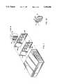
- FIG. 1is an exploded perspective view of a computer system chassis showing the rear panel having I/O ports and an associated I/O expansion box according to the principles of the invention.
- FIG 1ais an enlarged perspective view of the I/O expansion box shown in FIG. 1.
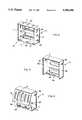
- FIG. 2is a perspective view of the bottom of the I/O expansion box shown in FIGS. 1 and 1a.
- FIG. 3is a perspective view of the cover of the I/O expansion box shown in FIGS. 1 and 1a.
- FIG. 4is a perspective view of another embodiment of a cover of an I/O expansion box according to the principles of the invention.
- FIG. 5is an exploded perspective view of the cover of FIG. 3 showing how connectors and cables are mounted.
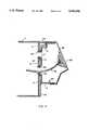
- FIG. 6is a perspective view of a "U" clip used to attach an I/O expansion box to a computer system chassis.
- FIG. 7is a cross-section view of an I/O expansion box bottom attached to the rear panel of a computer system chassis using the "U" clip of FIG. 6.
- FIG. 1There is illustrated in FIG. 1 a computer system chassis 7 and an associated I/O expansion box 1.
- FIG 1ais an enlarged view of the I/O expansion box 1 comprising a cover 3 and a bottom 5.
- the computer system chassis 7has a rear panel 4 with six I/O ports 9.
- a plastic bezel 44is attached to the chassis 7 to cover the rear panel 4 for aesthetic reasons.
- the bezel 44has openings 46 aligned to the I/O ports 9 on the rear panel 4. As shown, the openings 46 are substantially the same size but slightly larger than the I/O ports 9.
- Added functionality to the computer system chassis 7is provided by the I/O expansion box 1.
- the I/O expansion box 1allows an increase from six I/O ports to eight I/O ports and mates with two of the I/O ports 9 of the computer chassis 7. Further expansion is possible by using different embodiments of the expansion boxes according to the invention.
- the I/O expansion boxconsists of a bottom 5 and a cover 3.
- the bottom 5has a base plate 6 and lateral side walls 11 that extend normally away from the base plate 6 to form a recess 13.
- the base plate 6has two openings 15; each of the openings 15 has lips 17 to attach the bottom 5 to the rear panel 4 at I/O ports 9.
- the lips 17, as shown in FIG. 2extend outwardly of the base plate 6 away from the recess 13 and are shaped for clipped attachment.
- the bottom 5is attached to the rear panel 4 of the chassis 7 at two adjacent I/O ports 9 by using a mounting arrangement using "U" clips 20.
- the lips 17 at each opening 15 of the base plate 6are aligned with the edges 40 of I/O ports 9 and are held in place by snapping on clip 20.
- the clip 20is made of stainless steel and coated with epoxy material. Additionally, the clips 20 act as edge protectors and cover the burrs on the lips 17 and the edges 40 of the I/O ports 9 thereby protecting the I/O cables that run through from chaffing against the burrs on the edges 40 and the lips 17.
- three adjacent side walls 11 of the bottom 5have tabs 22 that extend in an outward direction from the side walls 11. Additionally, two opposite side walls of the three adjacent side walls 11 have clips 24 that extend in an outward direction. As shown, the clips 24 are formed by a stamping operation, but can be formed using other methods. A fourth side wall 11 has slots 26 mechanically stamped out. Good results have been obtained by making the bottom 5 out of mild steel, while metallized plastic could also be used instead.
- the base plate 6 of the bottom 5is 3.8 inches long and 3.8 inches wide, the side walls 11 are 1.1 inches deep and each opening 15 on the base plate 6 is 2 inches by 1 inch in dimension.
- FIG. 3more clearly shows the details of cover 3.
- cover 3has a top 2 and lateral side walls 28 that extend normally away from the top 2 to form a recess 30. Opposite side walls 28 have openings 32.
- a third side wall 28has pivots 34 formed along its edge.
- the top 3has four openings 36 thereon that act as I/O ports for the attachment of electrical connectors 38 for I/O cables. Good results have been obtained by making the cover 3 out of mild steel, while other materials such as metallized plastic may also be used instead.
- an I/O expansion box 1When added functionality is required from a computer system, an I/O expansion box 1 is attached to the rear panel 4 of the computer chassis 7, to provide I/O ports for additional I/O cables.
- the I/O cablesare first exited out of the chassis 7 through I/O ports 9 and are then inserted through the openings 15 of the base plate 6 such that the recess 13 of the bottom 5 faces away from the rear panel 4.
- the bottom 5is then attached to the rear panel 4 by first aligning the lips 17 at the openings 15 of the base plate 6 to the edges 40 of the I/O ports 9 on the rear panel 4 of the chassis 7 and are then clamped together using clips 20 along edges of the lips 17 and the edges 40 of the I/O ports 9.
- the connectors 38 at the end of the I/O cablesare next attached to the openings 36 of the top plate 2 of the cover 3.
- the cover 3is then aligned with the bottom plate 5 such that the pivots 34 of the cover 3 are engaged with the slots 26 of the bottom plate 5.
- the cover 3is press fitted to the bottom plate 5 such that the side walls 28 of the cover 3 fit over the side walls 11 of the bottom 5.
- the clips 24 of side wall 11 of the bottom 5snap into the openings 32 stamped out in the side walls 28 of the cover 3, thereby holding the cover 3 and the bottom 5 together to form the expansion box 1.
- the recess 13 formed by the side walls 11 of the bottom 5 and the recess 30 formed by the side walls 28 of the cover 3together form a housing for the body of the electrical connectors 38 and I/O cables 42 that are attached to openings 36 of the cover 3 of the I/O expansion box 1.
- the tabs 22 that extend out from the side walls 11 of the bottom 5make contact with the side walls 28 of the cover 3 thereby providing physical continuity between the bottom 5 and the cover 3.
- the metal to metal contact established by attaching the bottom 5 to the rear panel 4 of the chassis 7 by the use of spring clips 20provides the path for the extension of the RF shield from the chassis 7 to the I/O expansion box 1.
- the RF shield for the expansion box 1is further extended from the bottom 5 to the cover 3 by the metal to metal contact established by the tabs 22 of the bottom 5 making contact with the side walls 28 of the cover 3 when the cover 3 and the bottom 5 are brought together to form the I/O expansion box 1. Consequently, the I/O expansion box 1 provides RF shielding without the use of any external RF filtering techniques.
- the cover 3can be designed differently to provide additional number of connector openings 36 for additional I/O ports as required for system upgrades.
- the cover 3includes six connector openings 36 to act as six I/O ports, thereby providing four additional I/O ports.
- the top 2 of the cover 3has slanting surfaces 48, 49 and 50, each surface being slanted with respect to the rear panel 4 of the computer system chassis 7. By providing a slanting top 2 the recess 30 is made larger thereby allowing more space within the I/O expansion box 1 for more I/O cables 42 and more connectors 38 to be connected to the cover 3.
- connectors 38attach to openings 36 on the top 3 at an angle effective to preventing the cables from crimping by accommodating the bend radius of the electrical cables that are attached to the connectors 38.
- the slant anglewill vary to accommodate different bending radii. Good results have been obtained by setting the angle formed between the slanted surface 48 and the rear panel 4 of the computer system chassis to be 19 degrees, and the angle between the slanted surface 50 and the rear panel 4 of the computer system chassis to be 31 degrees, when using cable 42 having a bend radius of 3 inches.
- the cover 3may be attached to the bottom 5 of FIG. 2 thereby forming an I/O expansion box 1 that provides six I/O ports.
Landscapes
- Engineering & Computer Science (AREA)
- Microelectronics & Electronic Packaging (AREA)
- Shielding Devices Or Components To Electric Or Magnetic Fields (AREA)
- Casings For Electric Apparatus (AREA)
Abstract
Description
Claims (11)
Priority Applications (1)
| Application Number | Priority Date | Filing Date | Title |
|---|---|---|---|
| US08/056,552US5383096A (en) | 1993-05-03 | 1993-05-03 | I/O expansion box |
Applications Claiming Priority (1)
| Application Number | Priority Date | Filing Date | Title |
|---|---|---|---|
| US08/056,552US5383096A (en) | 1993-05-03 | 1993-05-03 | I/O expansion box |
Publications (1)
| Publication Number | Publication Date |
|---|---|
| US5383096Atrue US5383096A (en) | 1995-01-17 |
Family
ID=22005152
Family Applications (1)
| Application Number | Title | Priority Date | Filing Date |
|---|---|---|---|
| US08/056,552Expired - Fee RelatedUS5383096A (en) | 1993-05-03 | 1993-05-03 | I/O expansion box |
Country Status (1)
| Country | Link |
|---|---|
| US (1) | US5383096A (en) |
Cited By (10)
| Publication number | Priority date | Publication date | Assignee | Title |
|---|---|---|---|---|
| US5742003A (en)* | 1996-08-12 | 1998-04-21 | Ho; Hsin Chien | Computer terminal box with improved grounding structure |
| US6140577A (en)* | 1998-10-08 | 2000-10-31 | Gateway 2000, Inc | Electronic chassis electro-magnetic interference seal and sealing device |
| US6339536B1 (en) | 1999-11-10 | 2002-01-15 | Dell Usa, L.P. | I/O shield bracket assembly |
| US6342674B1 (en)* | 1998-12-28 | 2002-01-29 | Hon Hai Precision Ind. Co., Ltd. | Double-Layered computer enclosure |
| US6550877B1 (en)* | 2001-03-30 | 2003-04-22 | Intel Corporation | Interchangeable and modular I/O panel |
| US20030082959A1 (en)* | 2001-10-31 | 2003-05-01 | Boswell Bryan D. | Controlling electronics across an RF barrier using a serial interface bus |
| US6607308B2 (en) | 2001-02-12 | 2003-08-19 | E20 Communications, Inc. | Fiber-optic modules with shielded housing/covers having mixed finger types |
| US6659655B2 (en) | 2001-02-12 | 2003-12-09 | E20 Communications, Inc. | Fiber-optic modules with housing/shielding |
| US20080304228A1 (en)* | 2007-06-06 | 2008-12-11 | Dell Products L.P. | Multi-Purpose Structural Support I/O Member For A Server |
| US10095279B2 (en)* | 2016-02-12 | 2018-10-09 | Fujitsu Technology Solutions Intellectual Property Gmbh | Assembly for a computer system and cable covering unit for an assembly |
Citations (3)
| Publication number | Priority date | Publication date | Assignee | Title |
|---|---|---|---|---|
| US4652969A (en)* | 1985-07-05 | 1987-03-24 | Racal Data Communications Inc. | Secure universal housing arrangement for enclosing electronic circuits |
| US4901205A (en)* | 1988-09-02 | 1990-02-13 | Ncr Corporation | Housing for electronic components |
| US4979075A (en)* | 1989-10-12 | 1990-12-18 | Compuadd, Corporation | Method and apparatus for controlling circuit expansion for consumer electronic systems |
- 1993
- 1993-05-03USUS08/056,552patent/US5383096A/ennot_activeExpired - Fee Related
Patent Citations (3)
| Publication number | Priority date | Publication date | Assignee | Title |
|---|---|---|---|---|
| US4652969A (en)* | 1985-07-05 | 1987-03-24 | Racal Data Communications Inc. | Secure universal housing arrangement for enclosing electronic circuits |
| US4901205A (en)* | 1988-09-02 | 1990-02-13 | Ncr Corporation | Housing for electronic components |
| US4979075A (en)* | 1989-10-12 | 1990-12-18 | Compuadd, Corporation | Method and apparatus for controlling circuit expansion for consumer electronic systems |
Cited By (13)
| Publication number | Priority date | Publication date | Assignee | Title |
|---|---|---|---|---|
| US5742003A (en)* | 1996-08-12 | 1998-04-21 | Ho; Hsin Chien | Computer terminal box with improved grounding structure |
| US6140577A (en)* | 1998-10-08 | 2000-10-31 | Gateway 2000, Inc | Electronic chassis electro-magnetic interference seal and sealing device |
| US6342674B1 (en)* | 1998-12-28 | 2002-01-29 | Hon Hai Precision Ind. Co., Ltd. | Double-Layered computer enclosure |
| US6339536B1 (en) | 1999-11-10 | 2002-01-15 | Dell Usa, L.P. | I/O shield bracket assembly |
| US6607308B2 (en) | 2001-02-12 | 2003-08-19 | E20 Communications, Inc. | Fiber-optic modules with shielded housing/covers having mixed finger types |
| US6659655B2 (en) | 2001-02-12 | 2003-12-09 | E20 Communications, Inc. | Fiber-optic modules with housing/shielding |
| US6874953B2 (en) | 2001-02-12 | 2005-04-05 | Jds Uniphase Corporation | Methods and apparatus for fiber-optic modules with shielded housings/covers with fingers |
| US6550877B1 (en)* | 2001-03-30 | 2003-04-22 | Intel Corporation | Interchangeable and modular I/O panel |
| US20030082959A1 (en)* | 2001-10-31 | 2003-05-01 | Boswell Bryan D. | Controlling electronics across an RF barrier using a serial interface bus |
| US6813646B2 (en)* | 2001-10-31 | 2004-11-02 | Agilent Technologies, Inc. | Controlling electronics across an RF barrier using a serial interface bus |
| US20080304228A1 (en)* | 2007-06-06 | 2008-12-11 | Dell Products L.P. | Multi-Purpose Structural Support I/O Member For A Server |
| US7606044B2 (en)* | 2007-06-06 | 2009-10-20 | Dell Products L.P. | Multi-purpose structural support I/O member for a server |
| US10095279B2 (en)* | 2016-02-12 | 2018-10-09 | Fujitsu Technology Solutions Intellectual Property Gmbh | Assembly for a computer system and cable covering unit for an assembly |
Similar Documents
| Publication | Publication Date | Title |
|---|---|---|
| US6793524B2 (en) | Multimedia outlet with protective cover | |
| US6682368B2 (en) | Electrical connector assembly utilizing multiple ground planes | |
| US4669802A (en) | Outlet for optical fiber connectors | |
| US6811415B2 (en) | Connector protecting device | |
| US5114036A (en) | Covering plate for a preset hole on a computer housing | |
| US4688868A (en) | Grounding gasket for D-shell connector | |
| US5383096A (en) | I/O expansion box | |
| US6132253A (en) | Connector having an auxiliary shielding device | |
| US6278617B1 (en) | Shield for electronic device | |
| US20090130917A1 (en) | Retaining and grounding clip for adapter module | |
| US6132254A (en) | Multi-port connection device | |
| US5984727A (en) | Mini electrical connector | |
| US5830008A (en) | Panel mountable connector | |
| US5446622A (en) | PC board cartridge for a computer terminal | |
| US5532428A (en) | Snap-in resilient emi grounding clip apparatus for computer structures | |
| US6309037B2 (en) | PCI I/O bracket retainer | |
| US5205758A (en) | Communications distribution interface unit assembly | |
| EP3018767B1 (en) | Panel mount header connector | |
| US6554642B1 (en) | Electrical connector | |
| US6097604A (en) | Carrier to facilitate installation of an electronic device into an enclosure | |
| US6166325A (en) | Shield panel structure | |
| JP2004531095A (en) | Electronic circuits, housings for electrical connection elements and contact springs, and electromagnetic shielding processes | |
| US9407077B2 (en) | Support frame for structured cabling system | |
| US6628514B2 (en) | Fastener for securing a data storage device to a bracket | |
| US5893776A (en) | Electrical connection strip with releasable mounting for mounting on brackets of different configurations |
Legal Events
| Date | Code | Title | Description |
|---|---|---|---|
| AS | Assignment | Owner name:DIGITAL EQUIPMENT CORPORATION, MASSACHUSETTS Free format text:ASSIGNMENT OF ASSIGNORS INTEREST;ASSIGNORS:BENSON, MATTHEW CLAUS;MAZZONE, LAURENCE MICHAEL;REEL/FRAME:006533/0861 Effective date:19930430 | |
| FEPP | Fee payment procedure | Free format text:PAYOR NUMBER ASSIGNED (ORIGINAL EVENT CODE: ASPN); ENTITY STATUS OF PATENT OWNER: LARGE ENTITY | |
| FPAY | Fee payment | Year of fee payment:4 | |
| AS | Assignment | Owner name:COMPAQ INFORMATION TECHNOLOGIES GROUP, L.P., TEXAS Free format text:ASSIGNMENT OF ASSIGNORS INTEREST;ASSIGNORS:DIGITAL EQUIPMENT CORPORATION;COMPAQ COMPUTER CORPORATION;REEL/FRAME:012447/0903;SIGNING DATES FROM 19991209 TO 20010620 | |
| FPAY | Fee payment | Year of fee payment:8 | |
| AS | Assignment | Owner name:HEWLETT-PACKARD DEVELOPMENT COMPANY, L.P., TEXAS Free format text:CHANGE OF NAME;ASSIGNOR:COMPAQ INFORMANTION TECHNOLOGIES GROUP LP;REEL/FRAME:014102/0224 Effective date:20021001 | |
| REMI | Maintenance fee reminder mailed | ||
| LAPS | Lapse for failure to pay maintenance fees | ||
| LAPS | Lapse for failure to pay maintenance fees | Free format text:PATENT EXPIRED FOR FAILURE TO PAY MAINTENANCE FEES (ORIGINAL EVENT CODE: EXP.); ENTITY STATUS OF PATENT OWNER: LARGE ENTITY | |
| STCH | Information on status: patent discontinuation | Free format text:PATENT EXPIRED DUE TO NONPAYMENT OF MAINTENANCE FEES UNDER 37 CFR 1.362 | |
| FP | Lapsed due to failure to pay maintenance fee | Effective date:20070117 |