US5382952A - Transponder for proximity identification system - Google Patents
Transponder for proximity identification systemDownload PDFInfo
- Publication number
- US5382952A US5382952AUS07/823,784US82378492AUS5382952AUS 5382952 AUS5382952 AUS 5382952AUS 82378492 AUS82378492 AUS 82378492AUS 5382952 AUS5382952 AUS 5382952A
- Authority
- US
- United States
- Prior art keywords
- bits
- transponder
- signal
- binary
- identification
- Prior art date
- Legal status (The legal status is an assumption and is not a legal conclusion. Google has not performed a legal analysis and makes no representation as to the accuracy of the status listed.)
- Expired - Lifetime
Links
Images

Classifications
- G—PHYSICS
- G06—COMPUTING OR CALCULATING; COUNTING
- G06K—GRAPHICAL DATA READING; PRESENTATION OF DATA; RECORD CARRIERS; HANDLING RECORD CARRIERS
- G06K19/00—Record carriers for use with machines and with at least a part designed to carry digital markings
- G06K19/06—Record carriers for use with machines and with at least a part designed to carry digital markings characterised by the kind of the digital marking, e.g. shape, nature, code
- G06K19/067—Record carriers with conductive marks, printed circuits or semiconductor circuit elements, e.g. credit or identity cards also with resonating or responding marks without active components
- G06K19/07—Record carriers with conductive marks, printed circuits or semiconductor circuit elements, e.g. credit or identity cards also with resonating or responding marks without active components with integrated circuit chips
- G06K19/077—Constructional details, e.g. mounting of circuits in the carrier
- G06K19/07749—Constructional details, e.g. mounting of circuits in the carrier the record carrier being capable of non-contact communication, e.g. constructional details of the antenna of a non-contact smart card
- G06K19/07773—Antenna details
- G06K19/07788—Antenna details the antenna being of the capacitive type
- G—PHYSICS
- G01—MEASURING; TESTING
- G01S—RADIO DIRECTION-FINDING; RADIO NAVIGATION; DETERMINING DISTANCE OR VELOCITY BY USE OF RADIO WAVES; LOCATING OR PRESENCE-DETECTING BY USE OF THE REFLECTION OR RERADIATION OF RADIO WAVES; ANALOGOUS ARRANGEMENTS USING OTHER WAVES
- G01S13/00—Systems using the reflection or reradiation of radio waves, e.g. radar systems; Analogous systems using reflection or reradiation of waves whose nature or wavelength is irrelevant or unspecified
- G01S13/74—Systems using reradiation of radio waves, e.g. secondary radar systems; Analogous systems
- G01S13/75—Systems using reradiation of radio waves, e.g. secondary radar systems; Analogous systems using transponders powered from received waves, e.g. using passive transponders, or using passive reflectors
- G01S13/751—Systems using reradiation of radio waves, e.g. secondary radar systems; Analogous systems using transponders powered from received waves, e.g. using passive transponders, or using passive reflectors wherein the responder or reflector radiates a coded signal
- G01S13/758—Systems using reradiation of radio waves, e.g. secondary radar systems; Analogous systems using transponders powered from received waves, e.g. using passive transponders, or using passive reflectors wherein the responder or reflector radiates a coded signal using a signal generator powered by the interrogation signal
- G—PHYSICS
- G01—MEASURING; TESTING
- G01S—RADIO DIRECTION-FINDING; RADIO NAVIGATION; DETERMINING DISTANCE OR VELOCITY BY USE OF RADIO WAVES; LOCATING OR PRESENCE-DETECTING BY USE OF THE REFLECTION OR RERADIATION OF RADIO WAVES; ANALOGOUS ARRANGEMENTS USING OTHER WAVES
- G01S13/00—Systems using the reflection or reradiation of radio waves, e.g. radar systems; Analogous systems using reflection or reradiation of waves whose nature or wavelength is irrelevant or unspecified
- G01S13/74—Systems using reradiation of radio waves, e.g. secondary radar systems; Analogous systems
- G01S13/76—Systems using reradiation of radio waves, e.g. secondary radar systems; Analogous systems wherein pulse-type signals are transmitted
- G01S13/767—Responders; Transponders
- G—PHYSICS
- G06—COMPUTING OR CALCULATING; COUNTING
- G06K—GRAPHICAL DATA READING; PRESENTATION OF DATA; RECORD CARRIERS; HANDLING RECORD CARRIERS
- G06K19/00—Record carriers for use with machines and with at least a part designed to carry digital markings
- G06K19/06—Record carriers for use with machines and with at least a part designed to carry digital markings characterised by the kind of the digital marking, e.g. shape, nature, code
- G06K19/067—Record carriers with conductive marks, printed circuits or semiconductor circuit elements, e.g. credit or identity cards also with resonating or responding marks without active components
- G06K19/07—Record carriers with conductive marks, printed circuits or semiconductor circuit elements, e.g. credit or identity cards also with resonating or responding marks without active components with integrated circuit chips
- G06K19/077—Constructional details, e.g. mounting of circuits in the carrier
- G06K19/07749—Constructional details, e.g. mounting of circuits in the carrier the record carrier being capable of non-contact communication, e.g. constructional details of the antenna of a non-contact smart card
- G—PHYSICS
- G06—COMPUTING OR CALCULATING; COUNTING
- G06K—GRAPHICAL DATA READING; PRESENTATION OF DATA; RECORD CARRIERS; HANDLING RECORD CARRIERS
- G06K7/00—Methods or arrangements for sensing record carriers, e.g. for reading patterns
- G06K7/10—Methods or arrangements for sensing record carriers, e.g. for reading patterns by electromagnetic radiation, e.g. optical sensing; by corpuscular radiation
- G06K7/10009—Methods or arrangements for sensing record carriers, e.g. for reading patterns by electromagnetic radiation, e.g. optical sensing; by corpuscular radiation sensing by radiation using wavelengths larger than 0.1 mm, e.g. radio-waves or microwaves
- G06K7/10316—Methods or arrangements for sensing record carriers, e.g. for reading patterns by electromagnetic radiation, e.g. optical sensing; by corpuscular radiation sensing by radiation using wavelengths larger than 0.1 mm, e.g. radio-waves or microwaves using at least one antenna particularly designed for interrogating the wireless record carriers
- G06K7/10326—Methods or arrangements for sensing record carriers, e.g. for reading patterns by electromagnetic radiation, e.g. optical sensing; by corpuscular radiation sensing by radiation using wavelengths larger than 0.1 mm, e.g. radio-waves or microwaves using at least one antenna particularly designed for interrogating the wireless record carriers the antenna being of the very-near field type, e.g. capacitive
- H—ELECTRICITY
- H04—ELECTRIC COMMUNICATION TECHNIQUE
- H04B—TRANSMISSION
- H04B1/00—Details of transmission systems, not covered by a single one of groups H04B3/00 - H04B13/00; Details of transmission systems not characterised by the medium used for transmission
- H04B1/59—Responders; Transponders
- H—ELECTRICITY
- H04—ELECTRIC COMMUNICATION TECHNIQUE
- H04L—TRANSMISSION OF DIGITAL INFORMATION, e.g. TELEGRAPHIC COMMUNICATION
- H04L7/00—Arrangements for synchronising receiver with transmitter
- H04L7/04—Speed or phase control by synchronisation signals
- H04L7/041—Speed or phase control by synchronisation signals using special codes as synchronising signal
Definitions
- the present inventionrelates to an improved transponder for a proximity identification system. More particularly, the present invention relates to an improved transponder for an identification system of the type wherein an interrogator, located for example at a fixed installation, transmits an interrogating signal to activate a portable transponder type device or tag, which would ordinarily be carried by a person, an animal or an object, which is in the vicinity or proximity of the interrogator to cause the transponder to produce and transmit a coded identifying signal to a receiver conventionally located at the same location as the interrogator. The receiver, upon detection of a valid identifying code from the transponder then activates some system function, for example, to provide access to a controlled area or to keep track of the person, animal or object.
- an interrogatorlocated for example at a fixed installation, transmits an interrogating signal to activate a portable transponder type device or tag, which would ordinarily be carried by a person, an animal or an object, which is in the vicinity or proximity of the interrogator to cause the
- a transponderfor use in an object identification system including an interrogator which transmits a continuous interrogation signal and detects a responsive identification signal transmitted by the transponder, with the transponder comprising: means for receiving and detecting the interrogation signal; means, responsive to receipt of the interrogation signal, for continuously producing an identification signal having a frame with a fixed number of binary bits including a start bit corresponding to a first binary value, an identification data portion of a specified number of bits less than one half of the fixed number of bits, and a following synchronization portion including first, second and third consecutive bits of alternating binary values, with the first and the third bits being of the first binary value and the second bit being of a second binary value, followed by a sequence of bits which are all of the second binary value to complete the frame; means for producing a carrier signal; and means for modulating the carrier signal with the identification signal and for transmitting the modulated carrier signal.
- the bits in the synchronization portionconstitute one half of the fixed number of bits of the frame, the first binary value is a binary 1, and the fixed number of bits is equal to 64 or 128.
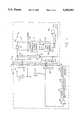
- FIG. 1is block circuit diagram of a proximity identification system.
- FIG. 2is a timing diagram showing the novel and coded identification signal including the novel synchronizing pattern produced according to the invention by the transponder of the system.
- the exciter or interrogator circuitwhich likewise functions as a power supply, consists of an oscillator 11, which puts out power at a convenient frequency f 0 , e.g. 400 or 125 kHz, and which is connected to a transmit coil antenna 13 tuned to resonate at the output frequency of oscillator 11 by means of a capacitor 15.
- Coil 13emits a strong electromagnetic field and is optionally provided with a Faraday shield to avoid capacitive or electrostatic coupling to the receiver portion of the transponder unit 9.
- the transponder unit or tag 9includes a receive antenna or coil 17 and a parallel connected capacitor 19 which form a tuned LC circuit which is resonant at the frequency f 0 of the oscillator 11.
- a half wave rectifier circuit 21 and a filter capacitor 23, which are connected to antenna coil 17 and capacitor 19,provide power for the remaining circuitry of the tag 9 through lines 25 and 27, the connections of which are not shown for simplicity.
- the high side of the receiving coil antenna 17is connected via a line 29 to the input of a frequency dividing counter 31 as a clock signal f 0 .
- the frequency dividing counter 31produces an R.F.
- the coded pulses on line 41occur at a much lower rate than the signal of frequency f 0 /2 on line 33.
- exclusive OR-gate 43is to bi-phase modulate the signal on line 33, which serves as a carrier frequency signal, with the coded pulse train on line 41, as described in greater detail in U.S. Pat. No. 4,818,855, the subject matter of which is incorporated herein by reference.
- the line 45is likewise connected to the gate 48 of an MOS transistor 49, for example an N channel enhancement mode transistor, having its drain 50 connected to the high side of coil 17 and its source 51 connected to ground.
- MOS transistor 49for example an N channel enhancement mode transistor
- the coded data on line 45is simultaneously coupled to the receiving antenna coil 17 which then likewise acts as an electromagnetic transmitting coil or antenna.
- the signals on line 45 fed to the electrostatic or electric field antenna 47 and to the antenna or coil 17are picked up respectively at the interrogator/reader 5 by a receiving electrostatic antenna 52, and a receiving electromagnetic antenna or coil 53, which are connected to, the input of a common preamplifier circuit 55.
- the output signals from the preamplifier 55are detected by a phase detector 57 and passed to a decoder 59 for validation. Assuming that the correct coded signal has been detected, an operating device 61 is then triggered.
- Operating device 61might take many forms, such as a security device for admitting one to a secure area, a device for recording the location of the person or object carrying the tag, and the like.
- transponder 5 of the illustrated systemutilizes both electromagnetic coupling and electrostatic coupling for simultaneous transmission of an encoded identification signal to the reader portion of the interrogator/reader 5, such is not required. That is, if desired only electrostatic coupling or only electromagnetic coupling may be utilized in a known manner.
- the stored signal or frameis comprised of a fixed number of binary bits, for example, 64 bits or 128 bits, including a single start bit 70 of a first binary value, a binary "1" as shown, followed by a data portion 71 with a specified number of binary data bits which, although shown schematically, are coded according to an identification value which identifies the transponder, followed by a synchronizing portion.
- the synchronizing portionconsists of three consecutive bits 72-74 with alternating binary values, i.e.
- the length of the data bit portion 71is less than one half of the total number of bits in the frame, and in the preferred embodiment is one bit less than one half of the total number of bits in the frame so that the sum of the start bit 70 and the data bits 71 is equal to one half of the total number of bits in the frame, i.e. 32 bits in the case of a 64 bit frame.
- the synchronizing patterns 72-75likewise contains one half of the total number of bits in the frame in the preferred embodiment. It should be noted, however, that although this arrangement is preferred, it is not absolutely necessary. For example, the number of bits 75 all with the same binary value "0" may be increased up to one half of the total number of bits in the frame. However, this of course reduces the number of available data bits 71 for identification purposes. It should further be noted that although the start bit 70 has been shown as the first bit of the frame, it is understood that, since the frame is continuously repeated by the transponder, the start bit 70 may likewise be considered to be the last bit of the frame, and thus to constitute part of the synchronization pattern.
- the total fixed pattern of the frame with the related binary valuesi.e. the start bit 70, the three consecutive alternating binary valued bits 72-74 and the following plurality of bits 75 with the same binary value, provide a unique synchronization pattern which is relatively simple to generate and to detect even in the presence of noise, and which is most difficult to falsify as a result of noise.
- the demodulated repeated frame of the identification signalare continuously searched for the presence of the synchronization pattern and only if the entire pattern is present with the relative polarities or binary values, i.e. the bit 70, 72-74 and the designated number of bits 75, is the data following the start bit 70 considered to be valid and read. If the synchronization pattern is not found, the demodulated data stream is continually searched for the synchronization pattern by shifting the stream bit by bit until an entire frame has been compared, i.e. a possible 64 comparisons in the case of a 64 bit frame.
- the polarity informationis lost and thus the polarity of the demodulated data stream may be reversed. Accordingly, if the synchronization pattern is not found after a maximum number of bit sequence comparisons, i.e. a number of comparisons equal to the total number of bits in the frame, preferably the polarity of the demodulated data signal is reversed and searched again for the presence of the synchronization pattern.
Landscapes
- Engineering & Computer Science (AREA)
- Radar, Positioning & Navigation (AREA)
- Remote Sensing (AREA)
- Physics & Mathematics (AREA)
- Computer Networks & Wireless Communication (AREA)
- General Physics & Mathematics (AREA)
- Theoretical Computer Science (AREA)
- Health & Medical Sciences (AREA)
- Computer Hardware Design (AREA)
- Toxicology (AREA)
- Microelectronics & Electronic Packaging (AREA)
- Signal Processing (AREA)
- Electromagnetism (AREA)
- General Health & Medical Sciences (AREA)
- Artificial Intelligence (AREA)
- Computer Vision & Pattern Recognition (AREA)
- Radar Systems Or Details Thereof (AREA)
- Near-Field Transmission Systems (AREA)
Abstract
Description
Claims (14)
Priority Applications (7)
| Application Number | Priority Date | Filing Date | Title |
|---|---|---|---|
| US07/823,784US5382952A (en) | 1992-01-22 | 1992-01-22 | Transponder for proximity identification system |
| PCT/US1993/000415WO1993015561A1 (en) | 1992-01-22 | 1993-01-22 | Improved transponder for proximity identification system |
| AU34771/93AAU668912B2 (en) | 1992-01-22 | 1993-01-22 | Improved transponder for proximity identification system |
| DE69302011TDE69302011T2 (en) | 1992-01-22 | 1993-01-22 | TRANSPONDER FOR A PROXIMITY IDENTIFICATION SYSTEM |
| CA002126874ACA2126874C (en) | 1992-01-22 | 1993-01-22 | Improved transponder for proximity identification system |
| JP5513286AJP3045774B2 (en) | 1992-01-22 | 1993-01-22 | Transponder for proximity identification system |
| EP93903545AEP0623260B1 (en) | 1992-01-22 | 1993-01-22 | Improved transponder for proximity identification system |
Applications Claiming Priority (1)
| Application Number | Priority Date | Filing Date | Title |
|---|---|---|---|
| US07/823,784US5382952A (en) | 1992-01-22 | 1992-01-22 | Transponder for proximity identification system |
Publications (1)
| Publication Number | Publication Date |
|---|---|
| US5382952Atrue US5382952A (en) | 1995-01-17 |
Family
ID=25239704
Family Applications (1)
| Application Number | Title | Priority Date | Filing Date |
|---|---|---|---|
| US07/823,784Expired - LifetimeUS5382952A (en) | 1992-01-22 | 1992-01-22 | Transponder for proximity identification system |
Country Status (7)
| Country | Link |
|---|---|
| US (1) | US5382952A (en) |
| EP (1) | EP0623260B1 (en) |
| JP (1) | JP3045774B2 (en) |
| AU (1) | AU668912B2 (en) |
| CA (1) | CA2126874C (en) |
| DE (1) | DE69302011T2 (en) |
| WO (1) | WO1993015561A1 (en) |
Cited By (39)
| Publication number | Priority date | Publication date | Assignee | Title |
|---|---|---|---|---|
| WO1996035189A3 (en)* | 1995-05-01 | 1996-12-05 | Motorola Indala Corp | Communication data format |
| WO1996041296A1 (en)* | 1995-06-07 | 1996-12-19 | Motorola Inc. | Automatically identifying objects deposited in a container |
| US5854481A (en)* | 1995-07-31 | 1998-12-29 | Sgs-Thomson Microelectronics, S.R.L. | Electronic cord and circuit with a switch for modifying the resonant frequency of a receiver |
| WO1999030432A1 (en)* | 1997-12-05 | 1999-06-17 | Koninklijke Philips Electronics N.V. | Identification transponder |
| US5955950A (en)* | 1998-07-24 | 1999-09-21 | Checkpoint Systems, Inc. | Low noise signal generator for use with an RFID system |
| US5959531A (en)* | 1998-07-24 | 1999-09-28 | Checkpoint Systems, Inc. | Optical interface between receiver and tag response signal analyzer in RFID system for detecting low power resonant tags |
| WO1999065002A1 (en)* | 1998-06-09 | 1999-12-16 | Motorola Inc. | Radio frequency identification tag having an article integrated antenna |
| WO2000016236A1 (en)* | 1998-09-11 | 2000-03-23 | Motorola Inc. | A contactless capacitive data transmission system and method |
| WO2001065479A3 (en)* | 2000-03-03 | 2001-12-20 | Koninkl Philips Electronics Nv | Data carrier having means for synchronization with a received data stream |
| US6392544B1 (en)* | 2000-09-25 | 2002-05-21 | Motorola, Inc. | Method and apparatus for selectively activating radio frequency identification tags that are in close proximity |
| US6411199B1 (en) | 1998-08-21 | 2002-06-25 | Keri Systems, Inc. | Radio frequency identification system |
| EP1068738A4 (en)* | 1998-03-13 | 2002-07-03 | Motorola Inc | Synchronization method for rfid system including tags having different memory sizes |
| US6445296B1 (en)* | 1996-08-21 | 2002-09-03 | A.T.L. Agricultural Technology Limited | Identification apparatus |
| GB2377341A (en)* | 2001-06-01 | 2003-01-08 | George L Powell | Signal sampling to reduce noise effects in an identification system |
| US20030169169A1 (en)* | 2000-08-17 | 2003-09-11 | Luc Wuidart | Antenna generating an electromagnetic field for transponder |
| US6771981B1 (en) | 2000-08-02 | 2004-08-03 | Nokia Mobile Phones Ltd. | Electronic device cover with embedded radio frequency (RF) transponder and methods of using same |
| US20040188531A1 (en)* | 2003-03-24 | 2004-09-30 | Gengel Glenn W. | RFID tags and processes for producing RFID tags |
| US6816083B2 (en) | 2002-02-04 | 2004-11-09 | Nokia Corporation | Electronic device with cover including a radio frequency indentification module |
| US20050017068A1 (en)* | 1995-02-15 | 2005-01-27 | Zalewski Thomas W. | System and method of making payments using an electronic device cover with embedded transponder |
| USRE38702E1 (en) | 1992-02-11 | 2005-02-15 | Innovation 2 Market Limited | Security system |
| US20050190111A1 (en)* | 2000-07-18 | 2005-09-01 | King Patrick F. | Wireless communication device and method |
| US20050270752A1 (en)* | 2001-05-31 | 2005-12-08 | Credelle Thomas L | Electronic devices with small functional elements supported on a carrier |
| US20060109129A1 (en)* | 2004-11-22 | 2006-05-25 | Curt Carrender | Transponder incorporated into an electronic device |
| US20060109130A1 (en)* | 2004-11-22 | 2006-05-25 | Hattick John B | Radio frequency identification (RFID) tag for an item having a conductive layer included or attached |
| US20060109123A1 (en)* | 2004-11-22 | 2006-05-25 | Curt Carrender | Radio frequency identification (RFID) tag for an item having a conductive layer included or attached |
| US20070031992A1 (en)* | 2005-08-05 | 2007-02-08 | Schatz Kenneth D | Apparatuses and methods facilitating functional block deposition |
| US7214569B2 (en) | 2002-01-23 | 2007-05-08 | Alien Technology Corporation | Apparatus incorporating small-feature-size and large-feature-size components and method for making same |
| US7288432B2 (en) | 1999-03-16 | 2007-10-30 | Alien Technology Corporation | Electronic devices with small functional elements supported on a carrier |
| US7353598B2 (en) | 2004-11-08 | 2008-04-08 | Alien Technology Corporation | Assembly comprising functional devices and method of making same |
| US7411552B2 (en) | 2000-07-18 | 2008-08-12 | Mineral Lassen Llc | Grounded antenna for a wireless communication device and method |
| US20080201388A1 (en)* | 2007-02-20 | 2008-08-21 | Luke Wood | System and method for equipment tracking and preventative maintenance scheduling and verification |
| US20080203162A1 (en)* | 2005-04-14 | 2008-08-28 | Nxp B.V. | System for Sensing a Physical Property in a Plurality of Scanning Positions |
| US7452748B1 (en) | 2004-11-08 | 2008-11-18 | Alien Technology Corporation | Strap assembly comprising functional block deposited therein and method of making same |
| US20090001941A1 (en)* | 2007-06-29 | 2009-01-01 | Microsoft Corporation | Inductive Powering Surface for Powering Portable Devices |
| US7542301B1 (en) | 2005-06-22 | 2009-06-02 | Alien Technology Corporation | Creating recessed regions in a substrate and assemblies having such recessed regions |
| US7551141B1 (en) | 2004-11-08 | 2009-06-23 | Alien Technology Corporation | RFID strap capacitively coupled and method of making same |
| USRE43683E1 (en) | 2000-07-18 | 2012-09-25 | Mineral Lassen Llc | Wireless communication device and method for discs |
| US20130280033A1 (en)* | 2010-10-19 | 2013-10-24 | Renewable Energy Systems Americas Inc. | Systems and methods for avian mitigation for wind farms |
| US10996329B2 (en)* | 2016-08-22 | 2021-05-04 | Denso Corporation | Distance estimating system |
Families Citing this family (15)
| Publication number | Priority date | Publication date | Assignee | Title |
|---|---|---|---|---|
| US5142128A (en)* | 1990-05-04 | 1992-08-25 | Perkin Gregg S | Oilfield equipment identification apparatus |
| US6472975B1 (en)* | 1994-06-20 | 2002-10-29 | Avid Marketing, Inc. | Electronic identification system with improved sensitivity |
| US5602538A (en)* | 1994-07-27 | 1997-02-11 | Texas Instruments Incorporated | Apparatus and method for identifying multiple transponders |
| JP2698766B2 (en)* | 1995-01-11 | 1998-01-19 | ソニーケミカル株式会社 | Transceiver for non-contact type IC card system |
| US5940006A (en)* | 1995-12-12 | 1999-08-17 | Lucent Technologies Inc. | Enhanced uplink modulated backscatter system |
| KR19980033008A (en)* | 1996-10-21 | 1998-07-25 | 윌리엄비.켐플러 | Data Structure and Information Transmission Method of RF-ID System |
| US6347292B1 (en) | 1999-02-17 | 2002-02-12 | Den-Con Electronics, Inc. | Oilfield equipment identification method and apparatus |
| DE10304587A1 (en)* | 2003-02-05 | 2004-08-19 | Abb Research Ltd. | Magnetic field generating system with two dimensional winding arrangement e.g. for industrial robots, has winding connection line of each winding joined to coupling element for compensating mechanically conditioned deviations |
| US7159654B2 (en) | 2004-04-15 | 2007-01-09 | Varco I/P, Inc. | Apparatus identification systems and methods |
| US7958715B2 (en) | 2003-03-13 | 2011-06-14 | National Oilwell Varco, L.P. | Chain with identification apparatus |
| US7484625B2 (en) | 2003-03-13 | 2009-02-03 | Varco I/P, Inc. | Shale shakers and screens with identification apparatuses |
| SG143030A1 (en)* | 2004-01-30 | 2008-06-27 | Agency Science Tech & Res | Radio frequency identification and communication device |
| US8016037B2 (en) | 2004-04-15 | 2011-09-13 | National Oilwell Varco, L.P. | Drilling rigs with apparatus identification systems and methods |
| US9784041B2 (en) | 2004-04-15 | 2017-10-10 | National Oilwell Varco L.P. | Drilling rig riser identification apparatus |
| DE102006042547A1 (en)* | 2006-09-11 | 2008-03-27 | Bartec Gmbh | System for monitoring a danger zone, in particular a vehicle |
Citations (4)
| Publication number | Priority date | Publication date | Assignee | Title |
|---|---|---|---|---|
| US4353064A (en)* | 1981-01-14 | 1982-10-05 | Honeywell Inc. | Battery operated access control card |
| US4818855A (en)* | 1985-01-11 | 1989-04-04 | Indala Corporation | Identification system |
| US5028918A (en)* | 1989-12-18 | 1991-07-02 | Dairy Equipment Company | Identification transponder circuit |
| US5175418A (en)* | 1989-12-19 | 1992-12-29 | Sony Corporation | Information card system |
Family Cites Families (5)
| Publication number | Priority date | Publication date | Assignee | Title |
|---|---|---|---|---|
| GB2086170A (en)* | 1980-02-29 | 1982-05-06 | Shapiro Evgeny Moiseevich | Method of transmission of communications from a transponder to an interrogator and secondary radar system for its implementation |
| DE3276546D1 (en)* | 1981-01-21 | 1987-07-16 | Australian Meat & Live Stock | Remote identification of animals |
| ZA829121B (en)* | 1981-12-18 | 1983-09-28 | Senelco Ltd | Transmitter/responder systems |
| DE3786836T2 (en)* | 1986-05-30 | 1994-01-13 | Sharp Kk | Microwave data transmission device. |
| DE4003410A1 (en)* | 1990-02-05 | 1991-08-08 | Anatoli Stobbe | PORTABLE FIELD PROGRAMMABLE DETECTOR TAG |
- 1992
- 1992-01-22USUS07/823,784patent/US5382952A/ennot_activeExpired - Lifetime
- 1993
- 1993-01-22WOPCT/US1993/000415patent/WO1993015561A1/enactiveIP Right Grant
- 1993-01-22CACA002126874Apatent/CA2126874C/ennot_activeExpired - Lifetime
- 1993-01-22JPJP5513286Apatent/JP3045774B2/ennot_activeExpired - Lifetime
- 1993-01-22AUAU34771/93Apatent/AU668912B2/ennot_activeExpired
- 1993-01-22DEDE69302011Tpatent/DE69302011T2/ennot_activeExpired - Lifetime
- 1993-01-22EPEP93903545Apatent/EP0623260B1/ennot_activeExpired - Lifetime
Patent Citations (4)
| Publication number | Priority date | Publication date | Assignee | Title |
|---|---|---|---|---|
| US4353064A (en)* | 1981-01-14 | 1982-10-05 | Honeywell Inc. | Battery operated access control card |
| US4818855A (en)* | 1985-01-11 | 1989-04-04 | Indala Corporation | Identification system |
| US5028918A (en)* | 1989-12-18 | 1991-07-02 | Dairy Equipment Company | Identification transponder circuit |
| US5175418A (en)* | 1989-12-19 | 1992-12-29 | Sony Corporation | Information card system |
Cited By (72)
| Publication number | Priority date | Publication date | Assignee | Title |
|---|---|---|---|---|
| USRE38702E1 (en) | 1992-02-11 | 2005-02-15 | Innovation 2 Market Limited | Security system |
| US7155199B2 (en) | 1995-02-15 | 2006-12-26 | Nokia Mobile Phones Limited | System and method of making payments using an electronic device cover with embedded transponder |
| US20050017068A1 (en)* | 1995-02-15 | 2005-01-27 | Zalewski Thomas W. | System and method of making payments using an electronic device cover with embedded transponder |
| US5600683A (en)* | 1995-05-01 | 1997-02-04 | Motorola, Inc. | Communication data format |
| WO1996035189A3 (en)* | 1995-05-01 | 1996-12-05 | Motorola Indala Corp | Communication data format |
| WO1996041296A1 (en)* | 1995-06-07 | 1996-12-19 | Motorola Inc. | Automatically identifying objects deposited in a container |
| US5854481A (en)* | 1995-07-31 | 1998-12-29 | Sgs-Thomson Microelectronics, S.R.L. | Electronic cord and circuit with a switch for modifying the resonant frequency of a receiver |
| US6445296B1 (en)* | 1996-08-21 | 2002-09-03 | A.T.L. Agricultural Technology Limited | Identification apparatus |
| WO1999030432A1 (en)* | 1997-12-05 | 1999-06-17 | Koninklijke Philips Electronics N.V. | Identification transponder |
| EP1068738A4 (en)* | 1998-03-13 | 2002-07-03 | Motorola Inc | Synchronization method for rfid system including tags having different memory sizes |
| WO1999065002A1 (en)* | 1998-06-09 | 1999-12-16 | Motorola Inc. | Radio frequency identification tag having an article integrated antenna |
| US5959531A (en)* | 1998-07-24 | 1999-09-28 | Checkpoint Systems, Inc. | Optical interface between receiver and tag response signal analyzer in RFID system for detecting low power resonant tags |
| US5955950A (en)* | 1998-07-24 | 1999-09-21 | Checkpoint Systems, Inc. | Low noise signal generator for use with an RFID system |
| US6611198B1 (en) | 1998-08-21 | 2003-08-26 | Keri Systems Incorporated | Electronic reader for reading a special characteristic of an object |
| US6411199B1 (en) | 1998-08-21 | 2002-06-25 | Keri Systems, Inc. | Radio frequency identification system |
| WO2000016236A1 (en)* | 1998-09-11 | 2000-03-23 | Motorola Inc. | A contactless capacitive data transmission system and method |
| US7288432B2 (en) | 1999-03-16 | 2007-10-30 | Alien Technology Corporation | Electronic devices with small functional elements supported on a carrier |
| US7425467B2 (en) | 1999-03-16 | 2008-09-16 | Alien Technology Corporation | Web process interconnect in electronic assemblies |
| WO2001065479A3 (en)* | 2000-03-03 | 2001-12-20 | Koninkl Philips Electronics Nv | Data carrier having means for synchronization with a received data stream |
| US7411552B2 (en) | 2000-07-18 | 2008-08-12 | Mineral Lassen Llc | Grounded antenna for a wireless communication device and method |
| US20050190111A1 (en)* | 2000-07-18 | 2005-09-01 | King Patrick F. | Wireless communication device and method |
| US7460078B2 (en) | 2000-07-18 | 2008-12-02 | Mineral Lassen Llc | Wireless communication device and method |
| USRE43683E1 (en) | 2000-07-18 | 2012-09-25 | Mineral Lassen Llc | Wireless communication device and method for discs |
| US7397438B2 (en) | 2000-07-18 | 2008-07-08 | Mineral Lassen Llc | Wireless communication device and method |
| US20070001916A1 (en)* | 2000-07-18 | 2007-01-04 | Mineral Lassen Llc | Wireless communication device and method |
| US6771981B1 (en) | 2000-08-02 | 2004-08-03 | Nokia Mobile Phones Ltd. | Electronic device cover with embedded radio frequency (RF) transponder and methods of using same |
| US20100039337A1 (en)* | 2000-08-17 | 2010-02-18 | Stmicroelectronics S.A. | Electromagnetic field generation antenna for a transponder |
| US8130159B2 (en) | 2000-08-17 | 2012-03-06 | Stmicroelectronics S.A. | Electromagnetic field generation antenna for a transponder |
| US20030169169A1 (en)* | 2000-08-17 | 2003-09-11 | Luc Wuidart | Antenna generating an electromagnetic field for transponder |
| US6392544B1 (en)* | 2000-09-25 | 2002-05-21 | Motorola, Inc. | Method and apparatus for selectively activating radio frequency identification tags that are in close proximity |
| US20090271973A1 (en)* | 2001-05-31 | 2009-11-05 | Thomas Lloyd Credelle | Methods of Making a Radio Frequency Identification (RFID) Tags |
| US20050270757A1 (en)* | 2001-05-31 | 2005-12-08 | Credelle Thomas L | Electronic devices with small functional elements supported on a carrier |
| US7559131B2 (en) | 2001-05-31 | 2009-07-14 | Alien Technology Corporation | Method of making a radio frequency identification (RFID) tag |
| US7260882B2 (en) | 2001-05-31 | 2007-08-28 | Alien Technology Corporation | Methods for making electronic devices with small functional elements supported on a carriers |
| US6985361B2 (en) | 2001-05-31 | 2006-01-10 | Alien Technology Corporation | Electronic devices with small functional elements supported on a carrier |
| US20070256291A1 (en)* | 2001-05-31 | 2007-11-08 | Credelle Thomas L | Electronic devices with small functional elements supported on a carrier |
| US8516683B2 (en) | 2001-05-31 | 2013-08-27 | Alien Technology Corporation | Methods of making a radio frequency identification (RFID) tags |
| US20050270752A1 (en)* | 2001-05-31 | 2005-12-08 | Credelle Thomas L | Electronic devices with small functional elements supported on a carrier |
| GB2377341A (en)* | 2001-06-01 | 2003-01-08 | George L Powell | Signal sampling to reduce noise effects in an identification system |
| US7214569B2 (en) | 2002-01-23 | 2007-05-08 | Alien Technology Corporation | Apparatus incorporating small-feature-size and large-feature-size components and method for making same |
| US20070117274A1 (en)* | 2002-01-23 | 2007-05-24 | Susan Swindlehurst | Apparatus incorporating small-feature-size and large-feature-size components and method for making same |
| US6816083B2 (en) | 2002-02-04 | 2004-11-09 | Nokia Corporation | Electronic device with cover including a radio frequency indentification module |
| US20040188531A1 (en)* | 2003-03-24 | 2004-09-30 | Gengel Glenn W. | RFID tags and processes for producing RFID tags |
| US7489248B2 (en) | 2003-03-24 | 2009-02-10 | Alien Technology Corporation | RFID tags and processes for producing RFID tags |
| US8350703B2 (en) | 2003-03-24 | 2013-01-08 | Alien Technology Corporation | RFID tags and processes for producing RFID tags |
| US8912907B2 (en) | 2003-03-24 | 2014-12-16 | Alien Technology, Llc | RFID tags and processes for producing RFID tags |
| US7253735B2 (en) | 2003-03-24 | 2007-08-07 | Alien Technology Corporation | RFID tags and processes for producing RFID tags |
| US9418328B2 (en) | 2003-03-24 | 2016-08-16 | Ruizhang Technology Limited Company | RFID tags and processes for producing RFID tags |
| US20060267778A1 (en)* | 2003-03-24 | 2006-11-30 | Gengel Gleen W | RFID tags and processes for producing RFID tags |
| US7500610B1 (en) | 2004-11-08 | 2009-03-10 | Alien Technology Corporation | Assembly comprising a functional device and a resonator and method of making same |
| US7353598B2 (en) | 2004-11-08 | 2008-04-08 | Alien Technology Corporation | Assembly comprising functional devices and method of making same |
| US20090056113A1 (en)* | 2004-11-08 | 2009-03-05 | Craig Gordon S W | Strap assembly comprising functional block deposited therein and method of making same |
| US7967204B2 (en) | 2004-11-08 | 2011-06-28 | Alien Technology Corporation | Assembly comprising a functional device and a resonator and method of making same |
| US7551141B1 (en) | 2004-11-08 | 2009-06-23 | Alien Technology Corporation | RFID strap capacitively coupled and method of making same |
| US7452748B1 (en) | 2004-11-08 | 2008-11-18 | Alien Technology Corporation | Strap assembly comprising functional block deposited therein and method of making same |
| US7615479B1 (en) | 2004-11-08 | 2009-11-10 | Alien Technology Corporation | Assembly comprising functional block deposited therein |
| US9070063B2 (en) | 2004-11-22 | 2015-06-30 | Ruizhang Technology Limited Company | Radio frequency identification (RFID) tag for an item having a conductive layer included or attached |
| US7688206B2 (en) | 2004-11-22 | 2010-03-30 | Alien Technology Corporation | Radio frequency identification (RFID) tag for an item having a conductive layer included or attached |
| US20060109129A1 (en)* | 2004-11-22 | 2006-05-25 | Curt Carrender | Transponder incorporated into an electronic device |
| US20090320139A1 (en)* | 2004-11-22 | 2009-12-24 | Curt Carrender | Transponder incorporated into an electronic device |
| US20060109130A1 (en)* | 2004-11-22 | 2006-05-25 | Hattick John B | Radio frequency identification (RFID) tag for an item having a conductive layer included or attached |
| US8471709B2 (en) | 2004-11-22 | 2013-06-25 | Alien Technology Corporation | Radio frequency identification (RFID) tag for an item having a conductive layer included or attached |
| US7385284B2 (en) | 2004-11-22 | 2008-06-10 | Alien Technology Corporation | Transponder incorporated into an electronic device |
| US20060109123A1 (en)* | 2004-11-22 | 2006-05-25 | Curt Carrender | Radio frequency identification (RFID) tag for an item having a conductive layer included or attached |
| US20080203162A1 (en)* | 2005-04-14 | 2008-08-28 | Nxp B.V. | System for Sensing a Physical Property in a Plurality of Scanning Positions |
| US7542301B1 (en) | 2005-06-22 | 2009-06-02 | Alien Technology Corporation | Creating recessed regions in a substrate and assemblies having such recessed regions |
| US20070031992A1 (en)* | 2005-08-05 | 2007-02-08 | Schatz Kenneth D | Apparatuses and methods facilitating functional block deposition |
| US20080201388A1 (en)* | 2007-02-20 | 2008-08-21 | Luke Wood | System and method for equipment tracking and preventative maintenance scheduling and verification |
| US20090001941A1 (en)* | 2007-06-29 | 2009-01-01 | Microsoft Corporation | Inductive Powering Surface for Powering Portable Devices |
| US20130280033A1 (en)* | 2010-10-19 | 2013-10-24 | Renewable Energy Systems Americas Inc. | Systems and methods for avian mitigation for wind farms |
| US9581165B2 (en)* | 2010-10-19 | 2017-02-28 | Renewable Energy Systems Americas Inc. | Systems and methods for avian mitigation for wind farms |
| US10996329B2 (en)* | 2016-08-22 | 2021-05-04 | Denso Corporation | Distance estimating system |
Also Published As
| Publication number | Publication date |
|---|---|
| AU3477193A (en) | 1993-09-01 |
| AU668912B2 (en) | 1996-05-23 |
| CA2126874A1 (en) | 1993-08-05 |
| CA2126874C (en) | 2003-10-14 |
| JPH07506427A (en) | 1995-07-13 |
| DE69302011T2 (en) | 1996-10-31 |
| EP0623260A1 (en) | 1994-11-09 |
| JP3045774B2 (en) | 2000-05-29 |
| DE69302011D1 (en) | 1996-05-02 |
| WO1993015561A1 (en) | 1993-08-05 |
| EP0623260B1 (en) | 1996-03-27 |
Similar Documents
| Publication | Publication Date | Title |
|---|---|---|
| US5382952A (en) | Transponder for proximity identification system | |
| US4912471A (en) | Interrogator-responder communication system | |
| RU2156540C2 (en) | Identification system with querying unit and multiple responding units, responder of identification system | |
| US5099227A (en) | Proximity detecting apparatus | |
| EP0438250B1 (en) | System for reading and writing data from and into remote tags | |
| EP0209588B1 (en) | Identification system | |
| US5543798A (en) | Method of providing a synchronized data stream suitable for use in a combined FDX and HDX RF-ID system | |
| KR900008401B1 (en) | Gate management system | |
| US4931788A (en) | Transponder and interrogator | |
| US5041826A (en) | Identification system | |
| US7309002B2 (en) | Differential radio frequency identification reader | |
| DE69331556D1 (en) | Collection of various goods | |
| EP0826187B1 (en) | Communication data format | |
| JPH0231356B2 (en) | ||
| EP0369622A2 (en) | Proximity reading of coded tag | |
| GB2187916A (en) | Transponder presence indicator | |
| JP3526496B2 (en) | Non-contact identification device for access control | |
| JPS63284692A (en) | Contactless id card system | |
| KR20030017607A (en) | Transponder system with a communication station comprising station identification signal generating means | |
| JPH08320377A (en) | Interrogator |
Legal Events
| Date | Code | Title | Description |
|---|---|---|---|
| AS | Assignment | Owner name:INDALA CORPORATION, CALIFORNIA Free format text:ASSIGNMENT OF ASSIGNORS INTEREST.;ASSIGNOR:MILLER, KEVIN D.;REEL/FRAME:006061/0307 Effective date:19920211 | |
| STCF | Information on status: patent grant | Free format text:PATENTED CASE | |
| FEPP | Fee payment procedure | Free format text:PAT HLDR NO LONGER CLAIMS SMALL ENT STAT AS SMALL BUSINESS (ORIGINAL EVENT CODE: LSM2); ENTITY STATUS OF PATENT OWNER: LARGE ENTITY Free format text:PAYOR NUMBER ASSIGNED (ORIGINAL EVENT CODE: ASPN); ENTITY STATUS OF PATENT OWNER: LARGE ENTITY | |
| FPAY | Fee payment | Year of fee payment:4 | |
| AS | Assignment | Owner name:HID CORPORATION, CALIFORNIA Free format text:ASSIGNMENT OF ASSIGNORS INTEREST;ASSIGNOR:MOTOROLA, INC.;REEL/FRAME:012454/0229 Effective date:20011031 | |
| FPAY | Fee payment | Year of fee payment:8 | |
| FPAY | Fee payment | Year of fee payment:12 | |
| AS | Assignment | Owner name:HID GLOBAL CORPORATION, CALIFORNIA Free format text:CHANGE OF NAME;ASSIGNOR:HID CORPORATION;REEL/FRAME:018951/0909 Effective date:20060501 | |
| AS | Assignment | Owner name:ASSA ABLOY IDENTIFICATION TECHNOLOGY GROUP AB, SWE Free format text:ASSIGNMENT OF ASSIGNORS INTEREST;ASSIGNOR:HID GLOBAL CORPORATION;REEL/FRAME:019317/0001 Effective date:20070409 | |
| AS | Assignment | Owner name:ASSA ABLOY AB, SWEDEN Free format text:ASSIGNMENT OF ASSIGNORS INTEREST;ASSIGNOR:ASSA ABLOY IDENTIFICATION TECHNOLOGY GROUP AB;REEL/FRAME:020196/0110 Effective date:20071122 Owner name:ASSA ABLOY AB,SWEDEN Free format text:ASSIGNMENT OF ASSIGNORS INTEREST;ASSIGNOR:ASSA ABLOY IDENTIFICATION TECHNOLOGY GROUP AB;REEL/FRAME:020196/0110 Effective date:20071122 |