US5382213A - Mechanical device for tool clamping in adaptors - Google Patents
Mechanical device for tool clamping in adaptorsDownload PDFInfo
- Publication number
- US5382213A US5382213AUS08/102,036US10203693AUS5382213AUS 5382213 AUS5382213 AUS 5382213AUS 10203693 AUS10203693 AUS 10203693AUS 5382213 AUS5382213 AUS 5382213A
- Authority
- US
- United States
- Prior art keywords
- spindle
- tool
- wrench
- tool locking
- frame
- Prior art date
- Legal status (The legal status is an assumption and is not a legal conclusion. Google has not performed a legal analysis and makes no representation as to the accuracy of the status listed.)
- Expired - Lifetime
Links
Images


Classifications
- B—PERFORMING OPERATIONS; TRANSPORTING
- B23—MACHINE TOOLS; METAL-WORKING NOT OTHERWISE PROVIDED FOR
- B23Q—DETAILS, COMPONENTS, OR ACCESSORIES FOR MACHINE TOOLS, e.g. ARRANGEMENTS FOR COPYING OR CONTROLLING; MACHINE TOOLS IN GENERAL CHARACTERISED BY THE CONSTRUCTION OF PARTICULAR DETAILS OR COMPONENTS; COMBINATIONS OR ASSOCIATIONS OF METAL-WORKING MACHINES, NOT DIRECTED TO A PARTICULAR RESULT
- B23Q3/00—Devices holding, supporting, or positioning work or tools, of a kind normally removable from the machine
- B23Q3/12—Devices holding, supporting, or positioning work or tools, of a kind normally removable from the machine for securing to a spindle in general
- B—PERFORMING OPERATIONS; TRANSPORTING
- B23—MACHINE TOOLS; METAL-WORKING NOT OTHERWISE PROVIDED FOR
- B23Q—DETAILS, COMPONENTS, OR ACCESSORIES FOR MACHINE TOOLS, e.g. ARRANGEMENTS FOR COPYING OR CONTROLLING; MACHINE TOOLS IN GENERAL CHARACTERISED BY THE CONSTRUCTION OF PARTICULAR DETAILS OR COMPONENTS; COMBINATIONS OR ASSOCIATIONS OF METAL-WORKING MACHINES, NOT DIRECTED TO A PARTICULAR RESULT
- B23Q11/00—Accessories fitted to machine tools for keeping tools or parts of the machine in good working condition or for cooling work; Safety devices specially combined with or arranged in, or specially adapted for use in connection with, machine tools
- B23Q11/0078—Safety devices protecting the operator, e.g. against accident or noise
- B23Q11/0092—Safety devices protecting the operator, e.g. against accident or noise actuating braking or stopping means
- B—PERFORMING OPERATIONS; TRANSPORTING
- B23—MACHINE TOOLS; METAL-WORKING NOT OTHERWISE PROVIDED FOR
- B23B—TURNING; BORING
- B23B31/00—Chucks; Expansion mandrels; Adaptations thereof for remote control
- B23B31/02—Chucks
- B23B31/10—Chucks characterised by the retaining or gripping devices or their immediate operating means
- B—PERFORMING OPERATIONS; TRANSPORTING
- B23—MACHINE TOOLS; METAL-WORKING NOT OTHERWISE PROVIDED FOR
- B23P—METAL-WORKING NOT OTHERWISE PROVIDED FOR; COMBINED OPERATIONS; UNIVERSAL MACHINE TOOLS
- B23P19/00—Machines for simply fitting together or separating metal parts or objects, or metal and non-metal parts, whether or not involving some deformation; Tools or devices therefor so far as not provided for in other classes
- B23P19/04—Machines for simply fitting together or separating metal parts or objects, or metal and non-metal parts, whether or not involving some deformation; Tools or devices therefor so far as not provided for in other classes for assembling or disassembling parts
- Y—GENERAL TAGGING OF NEW TECHNOLOGICAL DEVELOPMENTS; GENERAL TAGGING OF CROSS-SECTIONAL TECHNOLOGIES SPANNING OVER SEVERAL SECTIONS OF THE IPC; TECHNICAL SUBJECTS COVERED BY FORMER USPC CROSS-REFERENCE ART COLLECTIONS [XRACs] AND DIGESTS
- Y10—TECHNICAL SUBJECTS COVERED BY FORMER USPC
- Y10S—TECHNICAL SUBJECTS COVERED BY FORMER USPC CROSS-REFERENCE ART COLLECTIONS [XRACs] AND DIGESTS
- Y10S279/00—Chucks or sockets
- Y10S279/90—Adapted for automatic tool changer
- Y—GENERAL TAGGING OF NEW TECHNOLOGICAL DEVELOPMENTS; GENERAL TAGGING OF CROSS-SECTIONAL TECHNOLOGIES SPANNING OVER SEVERAL SECTIONS OF THE IPC; TECHNICAL SUBJECTS COVERED BY FORMER USPC CROSS-REFERENCE ART COLLECTIONS [XRACs] AND DIGESTS
- Y10—TECHNICAL SUBJECTS COVERED BY FORMER USPC
- Y10T—TECHNICAL SUBJECTS COVERED BY FORMER US CLASSIFICATION
- Y10T29/00—Metal working
- Y10T29/53—Means to assemble or disassemble
- Y10T29/53022—Means to assemble or disassemble with means to test work or product
- Y—GENERAL TAGGING OF NEW TECHNOLOGICAL DEVELOPMENTS; GENERAL TAGGING OF CROSS-SECTIONAL TECHNOLOGIES SPANNING OVER SEVERAL SECTIONS OF THE IPC; TECHNICAL SUBJECTS COVERED BY FORMER USPC CROSS-REFERENCE ART COLLECTIONS [XRACs] AND DIGESTS
- Y10—TECHNICAL SUBJECTS COVERED BY FORMER USPC
- Y10T—TECHNICAL SUBJECTS COVERED BY FORMER US CLASSIFICATION
- Y10T483/00—Tool changing
- Y10T483/13—Tool changing with control means energized in response to activator stimulated by condition sensor
Definitions
- This inventionrelates to a tool locking and releasing device for use in locking and releasing cutting tools in and from tool holders.
- Machine toolsare increasingly designed for use with a number of tool heads which are sequentially mounted on the machine tool as required. There is therefore a clear requirement that the tool heads be readily available for use.
- Each tool headcomprises a tool holder designed to be mounted in a machine tool spindle. In each tool holder there is mounted an appropriate cutting tool which is locked in position by a tool locking member such as a locking nut or ring. Ready and rapid replacement of the cutting tools is clearly a prerequisite for achieving an uninterrupted supply of tool heads for use as required.
- the replacement of the cutting tools in the tool holdershas been effected manually by the manual loosening, by means of an appropriate wrench, of the tool locking member, the removal of the cutting tool and its replacement by another cutting tool, and the subsequent tightening of the locking member so as to retain the cutting tool securely in position in the tool holder.
- a manual regimeis very time consuming.
- the manual tightening of the tool locking membercarries with it the consequence that differing tool heads may have the cutting tools secured therein to differing extents as a result of differing degrees of tightening being imparted to the locking members.
- a tool locking and releasing devicecomprising a support frame; a spindle rotatably mounted on said frame; a socket formed in said spindle coaxial with an axis of rotation of said spindle and adapted to receive and retain a tool holder against relative rotational movement; rotational drive means mounted on said frame and coupled to said spindle for rotational displacement of said spindle in first and second opposite directional senses; torque control means for limiting the drive torque transmitted to said spindle to a predetermined magnitude; a support column mounted on said frame and directed substantially parallel to said rotational axis; a wrench support arm, directed substantially normally to said column, slidably mounted at one end thereof on said column; a wrench handle retainably coupled to an opposite end of said support arm and having a wrench head adapted to grip a tool locking member; the arrangement being such that application of a rotary drive to said spindle in said first directional sense results in the rotation of said tool holder and the tightening of said tool locking member with
- the tool holderwhen it is desired to replace a cutting tool in a tool holder, the tool holder is placed in the socket of the spindle so as to be rotatable with the spindle.
- the wrench support armis manipulated so that the wrench head effectively grips the locking member, thereby inhibiting any rotational displacement of the locking member with respect to the support frame, and a rotational drive in a first directional sense is imparted to the spindle by the drive means, thereby rotating the tool head with respect to the locking member so as to loosen the locking member sufficiently for the cutting tool to be readily removable therefrom.
- the removed cutting toolis replaced by another cutting tool whose tool shank is inserted into the tool holder, and now a rotational drive in a second and opposite sense is transmitted to the tool holder from the motor, thereby resulting in the rotational displacement of the tool holder with respect to the locking member and the consequent tightening of the locking member by a predetermined torque and the secure mounting of the cutting tool in the tool holder.
- the torque transmitted to the spindle and therefore to the tool holderis limited to a predetermined magnitude, and in this way it is ensured that all cutting tools are mounted in their respective tool holders and secured therein to the required degree.
- FIG. 1is an exploded view of a tool head for use with a cutting, device in accordance with the present invention
- FIG. 2is a side elevation of a tool locking and releasing device in accordance with the present invention.
- FIG. 3is a plan view from above of the device shown in FIG. 2;
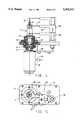
- FIG. 4is a view on an enlarged scale of a portion of the device shown in FIG. 2, partially longitudinally sectioned;
- FIG. 5is a view on an enlarged scale of a portion of the device shown in FIG. 3.
- a tool headcomprises a tool holder 1 having an upper cylindrical portion 1a and a lower, tapering portion 1b.
- a socket 2Formed in the upper cylindrical portion 1a is a socket 2.
- a collet 3is designed to fit into the socket 2 and to be surrounded by a locking nut 4 (constituting a locking member).
- a cutting tool 5is formed with a tool shank 5a which is designed to be fitted into the socket 2 via the locking nut 4 and collet 3.
- the tool locking and releasing devicecomprises a support frame 7 having an upper horizontal base frame 8 and support legs 9.
- a base plate 10is mounted on the horizontal base frame 8.
- Extending through a suitable aperture formed in the base plate 10 and secured theretois a cylindrical spindle support structure 11.
- a rotatable spindle 13Rotatably mounted within the spindle support structure 11, via bearings 12, is a rotatable spindle 13 in which is formed a socket 14 shaped to receive the tapering tool holder portion 1b and so as to retain the latter against relative rotational motion thereof with respect to the spindle 13.
- a drive motor 15(constituting rotational drive means) is supported with respect to the base plate 10 by means of a motor mounting frame 16 secured to the base 10.
- a drive shaft 17 of the motor 15is drive coupled to the spindle 13.
- the motor 15is provided with torque control means 18 for limiting the torque to be transmitted to the spindle to a predetermined magnitude.
- a wrench support arm 22is formed at one end with a cuff 23 which is slidable on the support column 19, and receives at its other end a wrench handle 24 which terminates in a wrench head 25.
- the degree to which the wrench handle 24 extends beyond the wrench support arm 22can be varied as required, and the wrench handle 24 can be clamped in position with respect to the wrench support arm 22 at the required degree of projection.
- a tool holder 1is positioned within the socket 14 of the spindle 13 and is rotatable together with the spindle 13.
- the wrench support arm 22, together with the wrench handle 24 and wrench head 25are moved aside as clearly shown in FIG. 5 of the drawings.
- the gripping of the latter by the wrench head 25is preceded by the following steps.
- the wrench support arm 22is moved to the side as shown in FIG. 5 of the drawings, the wrench handle 24 is displaced inwardly with respect to the wrench support arm 22 and the latter is moved so as to be located adjacent the locking nut 9, again as shown in chain dotted lines in FIG. 5 of the drawings.
- the wrench handle 24is now extended from the wrench support arm 22 until the wrench head 25 embraces the locking nut 4 and the procedure of loosening the latter (or, as to be explained below, the tightening) can proceed as described (or to be described).
- the device just describedaffords a very simple and effective means for the rapid replacement of cutting tools from the tool holders, whilst at the same time ensuring that the cutting tools are retained in the tool holders by a substantially constant clamping force and in a substantially constant, relative disposition.
Landscapes
- Engineering & Computer Science (AREA)
- Mechanical Engineering (AREA)
- Gripping On Spindles (AREA)
- Automatic Tool Replacement In Machine Tools (AREA)
Abstract
Description
This invention relates to a tool locking and releasing device for use in locking and releasing cutting tools in and from tool holders.
Machine tools are increasingly designed for use with a number of tool heads which are sequentially mounted on the machine tool as required. There is therefore a clear requirement that the tool heads be readily available for use. Each tool head comprises a tool holder designed to be mounted in a machine tool spindle. In each tool holder there is mounted an appropriate cutting tool which is locked in position by a tool locking member such as a locking nut or ring. Ready and rapid replacement of the cutting tools is clearly a prerequisite for achieving an uninterrupted supply of tool heads for use as required.
Hitherto, the replacement of the cutting tools in the tool holders has been effected manually by the manual loosening, by means of an appropriate wrench, of the tool locking member, the removal of the cutting tool and its replacement by another cutting tool, and the subsequent tightening of the locking member so as to retain the cutting tool securely in position in the tool holder. Clearly, such a manual regime is very time consuming. In addition, the manual tightening of the tool locking member carries with it the consequence that differing tool heads may have the cutting tools secured therein to differing extents as a result of differing degrees of tightening being imparted to the locking members.
There have been various prior proposals for the provision of power wrenches or otherwise to mechanize tool changing in machine tools (e.g. U.S. Pat. Nos. 3,380,324; 3,797,335), but in general they have been of relatively cumbersome, complicated construction.
It is an object of the present invention to provide a new and improved mechanized tool locking and releasing device in which the above-referred-to disadvantages are substantially reduced or overcome.
According to the present invention, there is provided a tool locking and releasing device comprising a support frame; a spindle rotatably mounted on said frame; a socket formed in said spindle coaxial with an axis of rotation of said spindle and adapted to receive and retain a tool holder against relative rotational movement; rotational drive means mounted on said frame and coupled to said spindle for rotational displacement of said spindle in first and second opposite directional senses; torque control means for limiting the drive torque transmitted to said spindle to a predetermined magnitude; a support column mounted on said frame and directed substantially parallel to said rotational axis; a wrench support arm, directed substantially normally to said column, slidably mounted at one end thereof on said column; a wrench handle retainably coupled to an opposite end of said support arm and having a wrench head adapted to grip a tool locking member; the arrangement being such that application of a rotary drive to said spindle in said first directional sense results in the rotation of said tool holder and the tightening of said tool locking member with a predetermined torque, and rotation of said spindle in said opposite directional sense results in the loosening of said tool locking member.
With such a device, when it is desired to replace a cutting tool in a tool holder, the tool holder is placed in the socket of the spindle so as to be rotatable with the spindle. The wrench support arm is manipulated so that the wrench head effectively grips the locking member, thereby inhibiting any rotational displacement of the locking member with respect to the support frame, and a rotational drive in a first directional sense is imparted to the spindle by the drive means, thereby rotating the tool head with respect to the locking member so as to loosen the locking member sufficiently for the cutting tool to be readily removable therefrom. The removed cutting tool is replaced by another cutting tool whose tool shank is inserted into the tool holder, and now a rotational drive in a second and opposite sense is transmitted to the tool holder from the motor, thereby resulting in the rotational displacement of the tool holder with respect to the locking member and the consequent tightening of the locking member by a predetermined torque and the secure mounting of the cutting tool in the tool holder. By virtue of the provision of the torque control means, the torque transmitted to the spindle and therefore to the tool holder is limited to a predetermined magnitude, and in this way it is ensured that all cutting tools are mounted in their respective tool holders and secured therein to the required degree.
For a better understanding of the present invention, and to show how the same may be carried out in practice, reference will now be made to the accompanying drawings, in which:
FIG. 1 is an exploded view of a tool head for use with a cutting, device in accordance with the present invention;
FIG. 2 is a side elevation of a tool locking and releasing device in accordance with the present invention;
FIG. 3 is a plan view from above of the device shown in FIG. 2;
FIG. 4 is a view on an enlarged scale of a portion of the device shown in FIG. 2, partially longitudinally sectioned; and
FIG. 5 is a view on an enlarged scale of a portion of the device shown in FIG. 3.
As seen in FIG. 1 of the drawings, a tool head comprises a tool holder 1 having an uppercylindrical portion 1a and a lower, taperingportion 1b. Formed in the uppercylindrical portion 1a is asocket 2. Acollet 3 is designed to fit into thesocket 2 and to be surrounded by a locking nut 4 (constituting a locking member). Acutting tool 5 is formed with atool shank 5a which is designed to be fitted into thesocket 2 via thelocking nut 4 andcollet 3.
With the fitting of thecutting tool shank 5a into thesocket 2, the tightening of thelocking nut 4 securely retains the cutting tool within the tool holder 1. It will be readily appreciated that, depending on the torque applied to thelocking nut 4, the degree of retention of the cutting tool within the tool holder can be varied; thus, the higher the torque, the greater the retaining force exerted on the tool and the greater the displacement into thesocket 2 of thetool shank 5. It is therefore clear that the ultimate retaining force and also the final location of the cutting tool extremity with respect to the tool holder 1 depends on the maximum turning torque applied to thelocking nut 4.
Referring now to FIGS. 2 through 5 of the drawings, the tool locking and releasing device comprises asupport frame 7 having an upperhorizontal base frame 8 andsupport legs 9. Abase plate 10 is mounted on thehorizontal base frame 8. Extending through a suitable aperture formed in thebase plate 10 and secured thereto is a cylindricalspindle support structure 11. Rotatably mounted within thespindle support structure 11, viabearings 12, is arotatable spindle 13 in which is formed asocket 14 shaped to receive the taperingtool holder portion 1b and so as to retain the latter against relative rotational motion thereof with respect to thespindle 13.
A drive motor 15 (constituting rotational drive means) is supported with respect to thebase plate 10 by means of amotor mounting frame 16 secured to thebase 10. Adrive shaft 17 of themotor 15 is drive coupled to thespindle 13. Themotor 15 is provided with torque control means 18 for limiting the torque to be transmitted to the spindle to a predetermined magnitude.
Mounted on thebase plate 10 is asupport column 19 which is substantially parallel to arotational axis 21 of thedrive shaft 17 andspindle 13. Awrench support arm 22 is formed at one end with acuff 23 which is slidable on thesupport column 19, and receives at its other end awrench handle 24 which terminates in awrench head 25. The degree to which thewrench handle 24 extends beyond thewrench support arm 22 can be varied as required, and thewrench handle 24 can be clamped in position with respect to thewrench support arm 22 at the required degree of projection.
In use, a tool holder 1 is positioned within thesocket 14 of thespindle 13 and is rotatable together with thespindle 13. In order to place the tool holder within thespindle 13, thewrench support arm 22, together with thewrench handle 24 andwrench head 25 are moved aside as clearly shown in FIG. 5 of the drawings.
If now it is desired to loosen and remove thecutting tool 5 from the tool holder 1, where thiscutting tool 5 is, as shown in the drawings, of lesser transverse dimensions than those of thelocking nut 4, the wrench support arm is slidably displaced along thecolumn 19 until it reaches its upper position shown in chain dotted lines in FIG. 4, whereupon the arm is then lowered until thewrench head 25 embraces thelocking nut 4. A rotational drive in a first sense is now imparted from themotor 15 via theshaft 17 andspindle 13 to the tool holder 1, whilst at the same time thewrench head 25 inhibits any relative rotational movement of thelocking nut 4. The rotation of the tool holder 1 results in the loosening of thelocking nut 4, permitting the ready removal of thecutting tool 5.
For the case where the lateral dimensions of thecutting tool 5 are greater than those of thelocking nut 4, the gripping of the latter by thewrench head 25 is preceded by the following steps. Thewrench support arm 22 is moved to the side as shown in FIG. 5 of the drawings, thewrench handle 24 is displaced inwardly with respect to thewrench support arm 22 and the latter is moved so as to be located adjacent thelocking nut 9, again as shown in chain dotted lines in FIG. 5 of the drawings. Thewrench handle 24 is now extended from thewrench support arm 22 until thewrench head 25 embraces thelocking nut 4 and the procedure of loosening the latter (or, as to be explained below, the tightening) can proceed as described (or to be described).
With the replacement of thecutting tool 5 by anew cutting tool 5, the latter is fixed in position. With thewrench head 25 embracing thelocking nut 4, a rotational drive in an opposite sense to that previously described is imparted by themotor 15 via theshaft 17 to thespindle 13, and thereby to the tool holder 1, whilst at the same time thelocking nut 4 is retained against rotational movement by means of thewrench head 25. A consequential tightening of thelocking nut 4 is effected. The provision of the torque control means 18 ensures that once the torque applied to the tool holder reaches the predetermined maximum, the drive to the tool holder is discontinued. In this way it is ensured that cutting tools are secured within the tool holders by a predetermined maximum torque. In consequence, the clamping force applied to the tool as well as the relative disposition of the cutting tool with respect to the tool holder are maintained constant. The tool holder with the replaced cutting tool can now be removed from the device (after thewrench handle 24 has been withdrawn into the wrench support arm 22).
It will be readily seen that the device just described affords a very simple and effective means for the rapid replacement of cutting tools from the tool holders, whilst at the same time ensuring that the cutting tools are retained in the tool holders by a substantially constant clamping force and in a substantially constant, relative disposition.
Claims (3)
1. A tool locking and releasing device comprising a support frame; a spindle rotatably mounted on said frame; a socket formed in said spindle coaxial with an axis of rotation of said spindle and adapted to receive and retain a tool holder against relative rotational movement; rotational drive means mounted on said frame and coupled to said spindle for rotational displacement of said spindle in first and second opposite directional senses; torque control means for limiting the drive torque transmitted to said spindle to a predetermined magnitude; a support column mounted on said frame and directed substantially parallel to said rotational axis; a wrench support arm, directed substantially normally to said column, slidably mounted at one end thereof on said column; a wrench handle retainably coupled to an opposite end of said support arm and having a wrench head adapted to grip a tool locking member, said wrench handle being axially displaceable with respect to said wrench support arm; the arrangement being such that application of a rotary drive to said spindle in said first directional sense results in the rotation of said tool holder and the tightening of said tool locking member with a predetermined torque, and rotation of said spindle in said opposite directional sense results in the loosening of said tool locking member.
2. A tool locking and releasing device according to claim 1, wherein said spindle is rotatably mounted via bearings on a spindle support structure which is in its turn mounted on said frame.
3. A tool locking and releasing device according to claim 1, wherein said wrench support arm is formed at said one end with a cuff member slidably mounted on said column.
Applications Claiming Priority (2)
| Application Number | Priority Date | Filing Date | Title |
|---|---|---|---|
| IL10273292AIL102732A (en) | 1992-08-05 | 1992-08-05 | Mechanical device for tool clamping in adaptors |
| IL102732 | 1992-08-05 |
Publications (1)
| Publication Number | Publication Date |
|---|---|
| US5382213Atrue US5382213A (en) | 1995-01-17 |
Family
ID=11063894
Family Applications (1)
| Application Number | Title | Priority Date | Filing Date |
|---|---|---|---|
| US08/102,036Expired - LifetimeUS5382213A (en) | 1992-08-05 | 1993-08-04 | Mechanical device for tool clamping in adaptors |
Country Status (6)
| Country | Link |
|---|---|
| US (1) | US5382213A (en) |
| EP (1) | EP0582269B1 (en) |
| JP (1) | JPH06170621A (en) |
| KR (1) | KR0145279B1 (en) |
| DE (1) | DE69300950T2 (en) |
| IL (1) | IL102732A (en) |
Cited By (10)
| Publication number | Priority date | Publication date | Assignee | Title |
|---|---|---|---|---|
| US6506143B1 (en)* | 1999-10-05 | 2003-01-14 | Honda Giken Kogyo Kabushiki Kaisha | Apparatus for finishing inside diameter of work |
| US20040005973A1 (en)* | 2002-07-03 | 2004-01-08 | Toshiba Kikai Kabushiki Kaisha | Tool replacement method and nut driver for machine tools |
| US20040213641A1 (en)* | 2001-03-07 | 2004-10-28 | Schraml Horst Karl | Device for diamond hollow drills |
| US20070004572A1 (en)* | 2005-06-30 | 2007-01-04 | Toshiba Kikai Kabushiki Kaisha | Automatic tool changing device and working machine |
| US7272877B2 (en) | 2000-12-18 | 2007-09-25 | Cardemon, Inc. | Adjustment method and apparatus for a boring tool |
| WO2020053824A1 (en)* | 2018-09-13 | 2020-03-19 | BURRON CASTAÑEDA, Marco Antonio | Automatic chuck-based tool changer |
| US10807210B2 (en) | 2016-06-07 | 2020-10-20 | Rego-Fix Ag | Clamping system |
| US20210252652A1 (en)* | 2020-02-17 | 2021-08-19 | Milwaukee Electric Tool Corporation | Electronic spindle lock for a power tool |
| CN114850554A (en)* | 2022-05-18 | 2022-08-05 | 南通威力数控机床有限公司 | Bidirectional tool magazine tool changing device of keyway planer and implementation method thereof |
| US20240123595A1 (en)* | 2022-10-12 | 2024-04-18 | Hilti Aktiengesellschaft | Method for Holding a Spindle of a Mobile Power Tool |
Families Citing this family (8)
| Publication number | Priority date | Publication date | Assignee | Title |
|---|---|---|---|---|
| US6350087B1 (en)* | 2000-07-07 | 2002-02-26 | Black & Decker Inc. | Tool-free collet tightener |
| JP4632153B2 (en)* | 2004-10-14 | 2011-02-16 | 鈴徳鉄工株式会社 | Tool chuck attachment / detachment device |
| JP4700436B2 (en)* | 2005-08-09 | 2011-06-15 | 株式会社アルプスツール | Tool for tool attachment / detachment |
| ITFI20130094A1 (en)* | 2013-04-30 | 2014-10-31 | Gianni Giovannini | TIGHTENING EQUIPMENT FOR TOOL HOLDERS |
| DE102018116263A1 (en)* | 2018-07-05 | 2020-01-09 | E. Zoller Gmbh & Co. Kg | Automated tool clamping device, tool setting and / or tool measuring device and method with an automated tool clamping device |
| JP7312059B2 (en)* | 2019-08-30 | 2023-07-20 | 共立精機株式会社 | Cutting tool changer and tool shape measurement system |
| CN110625148B (en)* | 2019-09-12 | 2020-06-12 | 重庆九源机械有限公司 | Power chuck for automobile steering joint shaft |
| DE102023114708A1 (en)* | 2023-06-05 | 2024-12-05 | E. Zoller GmbH & Co. KG Einstell- und Messgeräte | Tool clamping adapter for an automated tool clamping device for an automated clamping of a clamping nut |
Citations (15)
| Publication number | Priority date | Publication date | Assignee | Title |
|---|---|---|---|---|
| FR483531A (en)* | 1916-11-21 | 1917-07-13 | Ferdinand Girard | On-the-go lathe chuck system |
| US3380324A (en)* | 1966-04-18 | 1968-04-30 | Hillman Kelley | Power-wrench control system |
| US3680436A (en)* | 1970-10-12 | 1972-08-01 | Pratt & Whitney Inc | Tool changer clamp |
| US3797335A (en)* | 1973-05-29 | 1974-03-19 | L Amtsberg | Pneumatic nut running tool with governor shut-off control |
| DE7513937U (en)* | 1975-04-30 | 1975-09-11 | Hahn & Kolb | Chuck for tools that can be driven in rotation |
| SU560784A1 (en)* | 1974-07-31 | 1977-06-05 | Предприятие П/Я Р-6397 | Ship's underwater wing |
| US4151642A (en)* | 1976-10-04 | 1979-05-01 | General Dynamics Corporation | Device for pre-setting tools for numerical controlled machine |
| GB2026354A (en)* | 1978-07-26 | 1980-02-06 | Manyo Tool | Tool holder |
| DE3208621A1 (en)* | 1982-03-10 | 1983-09-22 | Fraunhofer-Gesellschaft zur Förderung der angewandten Forschung e.V., 8000 München | Tool clamping and replacement device |
| US4456271A (en)* | 1982-06-07 | 1984-06-26 | Houdaille Industries, Inc. | Tool holder with clamped position latch |
| US4581808A (en)* | 1982-02-04 | 1986-04-15 | The Charles Stark Draper Laboratory | Adjustable machining system and implement therefore |
| DE3604635A1 (en)* | 1985-02-16 | 1986-08-21 | Mori Machinery Co. Ltd., Okayama | MAJOR MINOR TOOLS FOR MACHINE TOOLS |
| FR2607048A1 (en)* | 1986-11-24 | 1988-05-27 | R M Robots | DEVICE FOR AUTHORIZING THE CHANGE OF TOOLS MOUNTED ON CHUCKS, IN PARTICULAR MILLING FOR MACHINE TOOLS, DIGITAL CONTROL MACHINING CENTERS AND SIMILAR MACHINES |
| US4761877A (en)* | 1985-08-31 | 1988-08-09 | Gebruder Honsberg Gmbh | Tool changer for machine tool |
| US5035556A (en)* | 1987-11-24 | 1991-07-30 | Aerospatiale Societe Nationale Industrielle | Machine for automatically regulating and measuring the length of extension and the diameter of a tool |
Family Cites Families (1)
| Publication number | Priority date | Publication date | Assignee | Title |
|---|---|---|---|---|
| ES2022394B3 (en)* | 1986-05-26 | 1991-12-01 | Aerospatiale Soc Nat Ind Soc Anonyme Dite: | MACHINE FOR AUTOMATIC REGULATION AND MEASUREMENT OF THE OUTLET LENGTH AND DIAMETER OF A TOOL. |
- 1992
- 1992-08-05ILIL10273292Apatent/IL102732A/ennot_activeIP Right Cessation
- 1993
- 1993-08-03DEDE69300950Tpatent/DE69300950T2/ennot_activeExpired - Lifetime
- 1993-08-03EPEP93112411Apatent/EP0582269B1/ennot_activeExpired - Lifetime
- 1993-08-04KRKR1019930015106Apatent/KR0145279B1/ennot_activeExpired - Fee Related
- 1993-08-04USUS08/102,036patent/US5382213A/ennot_activeExpired - Lifetime
- 1993-08-05JPJP5212102Apatent/JPH06170621A/enactivePending
Patent Citations (15)
| Publication number | Priority date | Publication date | Assignee | Title |
|---|---|---|---|---|
| FR483531A (en)* | 1916-11-21 | 1917-07-13 | Ferdinand Girard | On-the-go lathe chuck system |
| US3380324A (en)* | 1966-04-18 | 1968-04-30 | Hillman Kelley | Power-wrench control system |
| US3680436A (en)* | 1970-10-12 | 1972-08-01 | Pratt & Whitney Inc | Tool changer clamp |
| US3797335A (en)* | 1973-05-29 | 1974-03-19 | L Amtsberg | Pneumatic nut running tool with governor shut-off control |
| SU560784A1 (en)* | 1974-07-31 | 1977-06-05 | Предприятие П/Я Р-6397 | Ship's underwater wing |
| DE7513937U (en)* | 1975-04-30 | 1975-09-11 | Hahn & Kolb | Chuck for tools that can be driven in rotation |
| US4151642A (en)* | 1976-10-04 | 1979-05-01 | General Dynamics Corporation | Device for pre-setting tools for numerical controlled machine |
| GB2026354A (en)* | 1978-07-26 | 1980-02-06 | Manyo Tool | Tool holder |
| US4581808A (en)* | 1982-02-04 | 1986-04-15 | The Charles Stark Draper Laboratory | Adjustable machining system and implement therefore |
| DE3208621A1 (en)* | 1982-03-10 | 1983-09-22 | Fraunhofer-Gesellschaft zur Förderung der angewandten Forschung e.V., 8000 München | Tool clamping and replacement device |
| US4456271A (en)* | 1982-06-07 | 1984-06-26 | Houdaille Industries, Inc. | Tool holder with clamped position latch |
| DE3604635A1 (en)* | 1985-02-16 | 1986-08-21 | Mori Machinery Co. Ltd., Okayama | MAJOR MINOR TOOLS FOR MACHINE TOOLS |
| US4761877A (en)* | 1985-08-31 | 1988-08-09 | Gebruder Honsberg Gmbh | Tool changer for machine tool |
| FR2607048A1 (en)* | 1986-11-24 | 1988-05-27 | R M Robots | DEVICE FOR AUTHORIZING THE CHANGE OF TOOLS MOUNTED ON CHUCKS, IN PARTICULAR MILLING FOR MACHINE TOOLS, DIGITAL CONTROL MACHINING CENTERS AND SIMILAR MACHINES |
| US5035556A (en)* | 1987-11-24 | 1991-07-30 | Aerospatiale Societe Nationale Industrielle | Machine for automatically regulating and measuring the length of extension and the diameter of a tool |
Cited By (15)
| Publication number | Priority date | Publication date | Assignee | Title |
|---|---|---|---|---|
| US6506143B1 (en)* | 1999-10-05 | 2003-01-14 | Honda Giken Kogyo Kabushiki Kaisha | Apparatus for finishing inside diameter of work |
| US7272877B2 (en) | 2000-12-18 | 2007-09-25 | Cardemon, Inc. | Adjustment method and apparatus for a boring tool |
| US20040213641A1 (en)* | 2001-03-07 | 2004-10-28 | Schraml Horst Karl | Device for diamond hollow drills |
| US7229396B2 (en) | 2002-07-03 | 2007-06-12 | Toshiba Kikai Kabushiki Kaisha | Tool replacement method and nut driver for machine tools |
| US20070092349A1 (en)* | 2002-07-03 | 2007-04-26 | Toshiba Kikai Kabushiki Kaisha | Tool replacement method and nut driver for machine tools |
| US7144355B2 (en)* | 2002-07-03 | 2006-12-05 | Toshiba Kikai Kabushiki Kaisha | Tool replacement method and nut driver for machine tools |
| US20040005973A1 (en)* | 2002-07-03 | 2004-01-08 | Toshiba Kikai Kabushiki Kaisha | Tool replacement method and nut driver for machine tools |
| US20070004572A1 (en)* | 2005-06-30 | 2007-01-04 | Toshiba Kikai Kabushiki Kaisha | Automatic tool changing device and working machine |
| US7267642B2 (en)* | 2005-06-30 | 2007-09-11 | Toshiba Kikai Kabushiki Kaisha | Automatic tool changing device and working machine |
| US10807210B2 (en) | 2016-06-07 | 2020-10-20 | Rego-Fix Ag | Clamping system |
| WO2020053824A1 (en)* | 2018-09-13 | 2020-03-19 | BURRON CASTAÑEDA, Marco Antonio | Automatic chuck-based tool changer |
| US20210252652A1 (en)* | 2020-02-17 | 2021-08-19 | Milwaukee Electric Tool Corporation | Electronic spindle lock for a power tool |
| US11919117B2 (en)* | 2020-02-17 | 2024-03-05 | Milwaukee Electric Tool Corporation | Electronic spindle lock for a power tool |
| CN114850554A (en)* | 2022-05-18 | 2022-08-05 | 南通威力数控机床有限公司 | Bidirectional tool magazine tool changing device of keyway planer and implementation method thereof |
| US20240123595A1 (en)* | 2022-10-12 | 2024-04-18 | Hilti Aktiengesellschaft | Method for Holding a Spindle of a Mobile Power Tool |
Also Published As
| Publication number | Publication date |
|---|---|
| DE69300950T2 (en) | 1996-05-02 |
| IL102732A (en) | 1995-01-24 |
| DE69300950D1 (en) | 1996-01-18 |
| JPH06170621A (en) | 1994-06-21 |
| EP0582269A1 (en) | 1994-02-09 |
| EP0582269B1 (en) | 1995-12-06 |
| KR940005356A (en) | 1994-03-21 |
| IL102732A0 (en) | 1993-01-31 |
| KR0145279B1 (en) | 1998-07-01 |
Similar Documents
| Publication | Publication Date | Title |
|---|---|---|
| US5382213A (en) | Mechanical device for tool clamping in adaptors | |
| US4502457A (en) | Universal multiple angle work piece holder with multiple tool conversion features | |
| US4759666A (en) | Drill guides and apparatus for holding same | |
| JP2525149B2 (en) | Rotating tool support | |
| CN100563886C (en) | A kind of have an electric tool of exempting from the erecting tools sleeve assembly | |
| US5810522A (en) | Hand-held bar edging tool and support therefor | |
| US5165313A (en) | Bar puller for automatic lathe | |
| US5348319A (en) | Chuck utilizing cam | |
| EP0919327A2 (en) | Apparatus for sharpening dental instruments | |
| US4461594A (en) | Rotatably adjustable and lockable connector | |
| US4358971A (en) | Dentist's drill chuck | |
| EP0100421A2 (en) | Drill stand | |
| US5782588A (en) | Draw bar assisted rotary hole sawing | |
| US20130219692A1 (en) | Device and method for holding a tool bit | |
| JP2018202586A (en) | Hand-held polishing tool and polishing method | |
| US3981211A (en) | Self-centering tool holding apparatus | |
| US4652188A (en) | Centering tool | |
| CA2019681C (en) | Scroll saw wrench | |
| US4586856A (en) | Adjustable mobile support for electric drill | |
| US6102089A (en) | Assembly for converting a drill press into a wood lathe | |
| CA1138483A (en) | Workpiece support device and auxiliary support body arrangement | |
| US6032938A (en) | Carver's vise | |
| US3109336A (en) | Multiple tool holder for lathes or like machines | |
| US20210107072A1 (en) | Router Bit Holding Vise | |
| US6280125B1 (en) | R-8 collet |
Legal Events
| Date | Code | Title | Description |
|---|---|---|---|
| AS | Assignment | Owner name:ISCAR LTD. Free format text:ASSIGNMENT OF ASSIGNORS INTEREST;ASSIGNORS:KOPEL, SHIMON;DRORI, GIDEON;REEL/FRAME:006654/0407 Effective date:19930721 | |
| FEPP | Fee payment procedure | Free format text:PAYOR NUMBER ASSIGNED (ORIGINAL EVENT CODE: ASPN); ENTITY STATUS OF PATENT OWNER: LARGE ENTITY | |
| STCF | Information on status: patent grant | Free format text:PATENTED CASE | |
| FPAY | Fee payment | Year of fee payment:4 | |
| FPAY | Fee payment | Year of fee payment:8 | |
| FPAY | Fee payment | Year of fee payment:12 | |
| AS | Assignment | Owner name:NEW ISCAR LTD., ISRAEL Free format text:ASSIGNMENT OF ASSIGNORS INTEREST;ASSIGNOR:ISCAR LTD.;REEL/FRAME:017946/0623 Effective date:20060706 | |
| AS | Assignment | Owner name:ISCAR LTD., ISRAEL Free format text:CHANGE OF NAME;ASSIGNOR:NEW ISCAR LTD.;REEL/FRAME:018075/0253 Effective date:20060706 |