US5381224A - Scanning laser imaging system - Google Patents
Scanning laser imaging systemDownload PDFInfo
- Publication number
- US5381224A US5381224AUS08/113,172US11317293AUS5381224AUS 5381224 AUS5381224 AUS 5381224AUS 11317293 AUS11317293 AUS 11317293AUS 5381224 AUS5381224 AUS 5381224A
- Authority
- US
- United States
- Prior art keywords
- specimen
- light
- imaging system
- confocal
- detector
- Prior art date
- Legal status (The legal status is an assumption and is not a legal conclusion. Google has not performed a legal analysis and makes no representation as to the accuracy of the status listed.)
- Expired - Lifetime
Links
- 238000003384imaging methodMethods0.000titleclaimsdescription48
- 238000005424photoluminescenceMethods0.000claimsabstractdescription36
- 238000001514detection methodMethods0.000claimsabstractdescription21
- 239000004065semiconductorSubstances0.000claimsabstractdescription15
- 238000012634optical imagingMethods0.000claimsabstract3
- 230000003287optical effectEffects0.000claimsdescription14
- 238000001228spectrumMethods0.000claimsdescription7
- 238000000034methodMethods0.000claimsdescription4
- 230000003595spectral effectEffects0.000claimsdescription3
- 238000002073fluorescence micrographMethods0.000claimsdescription2
- 238000000103photoluminescence spectrumMethods0.000claimsdescription2
- 238000005286illuminationMethods0.000claims5
- 238000002189fluorescence spectrumMethods0.000claims1
- 238000013507mappingMethods0.000abstractdescription11
- 239000000499gelSubstances0.000abstractdescription7
- 230000007246mechanismEffects0.000abstractdescription7
- 238000012163sequencing techniqueMethods0.000abstractdescription5
- 108090000623proteins and genesProteins0.000abstractdescription4
- 238000010226confocal imagingMethods0.000abstractdescription3
- 238000005259measurementMethods0.000description7
- 210000001747pupilAnatomy0.000description6
- 238000001069Raman spectroscopyMethods0.000description3
- 230000005540biological transmissionEffects0.000description3
- 230000000694effectsEffects0.000description3
- 238000000799fluorescence microscopyMethods0.000description3
- 238000003745diagnosisMethods0.000description2
- 238000010586diagramMethods0.000description2
- 238000012986modificationMethods0.000description2
- 230000004048modificationEffects0.000description2
- 230000005855radiationEffects0.000description2
- 235000012431wafersNutrition0.000description2
- 206010028980NeoplasmDiseases0.000description1
- 201000011510cancerDiseases0.000description1
- 150000001875compoundsChemical class0.000description1
- 239000007850fluorescent dyeSubstances0.000description1
- 239000011521glassSubstances0.000description1
- 238000001727in vivoMethods0.000description1
- 239000000463materialSubstances0.000description1
- RGCLLPNLLBQHPF-HJWRWDBZSA-NphosphamidonChemical compoundCCN(CC)C(=O)C(\Cl)=C(/C)OP(=O)(OC)OCRGCLLPNLLBQHPF-HJWRWDBZSA-N0.000description1
- 229910021426porous siliconInorganic materials0.000description1
- 238000001454recorded imageMethods0.000description1
- 238000001055reflectance spectroscopyMethods0.000description1
- 239000002210silicon-based materialSubstances0.000description1
- 238000004611spectroscopical analysisMethods0.000description1
- 230000001360synchronised effectEffects0.000description1
- 239000012780transparent materialSubstances0.000description1
Images


Classifications
- G—PHYSICS
- G01—MEASURING; TESTING
- G01N—INVESTIGATING OR ANALYSING MATERIALS BY DETERMINING THEIR CHEMICAL OR PHYSICAL PROPERTIES
- G01N21/00—Investigating or analysing materials by the use of optical means, i.e. using sub-millimetre waves, infrared, visible or ultraviolet light
- G01N21/62—Systems in which the material investigated is excited whereby it emits light or causes a change in wavelength of the incident light
- G01N21/63—Systems in which the material investigated is excited whereby it emits light or causes a change in wavelength of the incident light optically excited
- G01N21/64—Fluorescence; Phosphorescence
- G01N21/645—Specially adapted constructive features of fluorimeters
- G01N21/6456—Spatial resolved fluorescence measurements; Imaging
Definitions
- This inventionrelates to the field of Scanning Laser Imaging Systems when used to image macroscopic specimens (i.e. specimens larger than those viewed through a microscope, which usually have a maximum size of 1 mm ⁇ 1 mm), including systems used to form Photoluminescence (PL) maps of semiconductor specimens, or images of semiconductor specimens in which the contrast mechanisms include reflected light, transmitted light, scattered light, lifetimes, optical beam induced current or voltage, and others.
- PLPhotoluminescence
- This inventionfurther relates to fluorescence (FL) images or maps of biological or other specimens, as well as reflected light images of these specimens.
- This inventionfurther relates to fluorescent gel scanning for gene sequencing, and also to the detection of fingerprints.
- Dixon and Damaskinosdisclosed several embodiments of a scanning beam imaging system using a laser scan lens to focus the incoming laser beam onto the specimen, and then using the same lens to collect the reflected light (or photoluminescence or fluorescence) returning from the specimen.
- Most laser scan lensesare designed to give a constant scan velocity on the focal plane when the angle of deflection (theta) of the incident beam is varied at a constant rate.
- Such lensesare called F Theta lenses, and the image height is proportional to f*theta, whereas the image height of an ordinary photographic objective, or of a microscope objective, is f*tan(theta).
- thetais the angle between the incoming beam and the optic axis of the scan lens (the scan angle)
- fis the focal length of the laser scan lens
- *denotes multiplication.
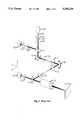
- FIG. 1One embodiment of the scanning beam imaging system disclosed in GB 9218482.9 is shown in FIG. 1.
- Light beam 103 from laser 102(or other light source) is focused on pinhole 106 by lens 104.
- the expanding beam exiting pinhole 106is focused to a parallel beam by lens 108.
- Lens 108(Lens 104, pinhole 106 and lens 108 constitute a spatial filter and beam expander.)
- the parallel, expanded beampasses through beamsplitter 112 and is deflected in the x-y plane by first scanning mirror 114, which rotates about an axis parallel to the z-direction.
- the beamthen passes through a unitary telescope comprised of lenses 116 and 118 and is brought back as a parallel beam to the center of second scanning mirror 120, which rotates about an axis parallel to the x-direction and imparts a deflection in the y-z plane.
- Lenses 122 and 124also comprising a unitary telescope, return the deflected beam to the center of beamsplitter 126, which is placed at the position of the entrance pupil of laser scan lens 128.
- Light reflected from beamsplitter 126is focused to a diffraction-limited spot on specimen 130 by laser scan lens 128.
- the scan systemis controlled electronically to produce a raster scan of the focus spot across the specimen.
- Light reflected from (or photoluminescence or fluorescence emitted by) specimen 130is collected by laser scan lens 128 and impinges on beamsplitter 126.
- Light passing through beamsplitter 126is collected by condenser lens 132 and falls on the active area of non-confocal detector 134.
- Condenser lens 132 and non-confocal detector 134comprise a non-confocal detection arm.
- Light reflected by beamsplitter 126passes back through the scan system, and part of this returning beam is reflected by beamsplitter 112 towards detector lens 136 which focuses the returning parallel beam onto confocal pinhole 138.
- Light passing through the confocal pinholeis detected by confocal detector 140.
- Detector lens 136, confocal pinhole 138 and confocal detector 140comprise a confocal detection arm.
- a confocal image of the specimencan be recorded pixel-by-pixel by digitizing the signal from confocal detector 140 using a slow-scan frame grabber synchronized to the mirror scan system.
- a non-confocal imagecan be recorded by digitizing the signal froth detector 134.
- laser scan lens 128is a telecentric F Theta lens.
- the image from detector 140is confocal, because Pinhole 138 rejects all light in the returning beam which is not parallel to the axis as it enters lens 136, and thus rejects all light that does not originate at the focal point of laser scan lens 128.
- detector 134The image detected by detector 134 is not confocal, and if beamsplitter 126 is a dichroic beamsplitter, then detector 134 can be used to detect fluorescence or photoluminescence from the specimen 130, without the reduction in intensity caused by the passage of the returning beam back through the scan system. This system works well in recording confocal images in reflected light, but performance is not as good in fluorescence and photoluminescence imaging, or for non-confocal imaging in reflected light.
- the amount of light emitted from the specimen in fluorescence or photoluminescenceis usually small, and only a small part of that is collected by laser scan lens 128, since Laser Scan Lenses have a much smaller Numerical Aperture (NA) than most objective lenses used for fluorescence microscopes.
- NANumerical Aperture
- most Laser Scan Lensesare not colour corrected, and they often provide diffraction-limited performance at only one wavelength, as well as having large changes in focal length with changes in wavelength.
- detector 140works well in reflected-light confocal imaging, the signal is very weak in confocal fluorescence or photoluminescence imaging, except from the brightest specimens. Colour-corrected Laser Scan Lenses are available, but they are complicated and very expensive.
- the confocal pinhole 138is very, effective at reducing flare, as well as rejecting any light returning from the specimen that does not originate at the focal point of laser scan lens 128.
- Both confocal and non-confocal detectorscan be used if required.
- Several different contrast mechanismsmay be used, including but not necessarily limited to the following: reflected light, transmitted light, photoluminescence (including spectrally-resolved photoluminescence), fluorescence (including spectrally-resolved fluorescence), fluorescence decay, scattered light, optical beam induced current or voltage, photoconductivity, scanning reflectance spectroscopy, photoreflectance spectroscopy, Raman effect imaging, and many others.
- a novel fluorescence imaging or mapping systemthat can assist diagnosis of cancer by comparing the fluorescence emission of cancerous tissue with that of the surrounding normal tissue, or by combining imaging in fluorescence and/or reflected light with another contrast mechanism (for example Raman Effect) to aid diagnosis.
- Some of the many combinationsare as follows: the combination of reflected light, photoluminescence and Optical Beam Induced Current imaging of semiconductors; the combination of reflected light, fluorescence, and Raman effect imaging of biomedical specimens. Measurements using different contrast mechanisms may be performed simultaneously, or sequentially, depending on the combination of measurements to be made.
- FIG. 1shows a prior art confocal scanning beam laser imaging system with both confocal and non-confocal detectors.
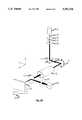
- FIG. 2ashows a simplified perspective view of a preferred embodiment of the present invention, a scanning beam imaging or mapping system for non-confocal reflected-light, photoluminescence or fluorescence imaging.
- FIG. 2bshows a simplified side view of the laser scan lens, specimen and detector area of the imaging system of FIG. 2a.
- FIG. 2cshows the same area of the instrument as shown in FIG. 2b, with the addition of a narrow-band transmission filter for spectrally-resolved imaging.
- FIG. 2dshows the imaging system of FIG. 2a, with the addition of an optical beam induced current detector.”
- FIG. 3ashows a simplified perspective view of a preferred embodiment of the present invention that includes both confocal and non-confocal detectors
- 3bshows an embodiment of the present invention in which the scan system combines a beam scan in one direction with a stage scan in the other, perpendicular direction.”
- the present inventionis a practical scanning beam imaging system for macroscopic specimens (macroscope) that can form images using several different contrast mechanisms.
- FIG. 2ashows a first preferred embodiment of the invention, a simple non-confocal scanning laser imaging system.
- light beam 103 from laser 102(or other light source) is focused on pinhole 106 by lens 104.
- the expanding beam exiting pinhole 106is focused to a parallel beam by lens 108.
- Lens 108(Lens 104, pinhole 106 and lens 108 constitute a spatial filter and beam expander.)
- the beam expansion ratiois chosen so that the expanded laser beam fills entrance pupil 250 of laser scan lens 128.
- the parallel, expanded beamis deflected in the x-y plane by first scanning mirror 114, passes through the entrance pupil 250 of laser scan lens 128, and is deflected in the y-z plane by second scanning mirror 120.
- a raster scanis impressed on the laser beam by scanning mirrors 114 and 120. These two scanning mirrors are placed close together, on either side of the entrance pupil of the laser scan lens.
- Laser scan lens 128focuses the beam through beamsplitter 252 to a spot on the specimen 130, and light reflected from (or emitted by) the specimen is partially reflected by beamsplitter 252 towards condenser lens 254, which is placed so that light collected from any position on the specimen falls on the active area of detector 256 as the scan proceeds.
- Condenser lens 254 and detector 256comprise a non-confocal detection arm. This embodiment has several advantages over non-confocal versions of the prior art macroscopes which used the laser scan lens to collect reflected light from the specimen.
- NAnumerical aperture
- FIG. 2bshows a close-up view of the laser scan lens, specimen and detector area of the macroscope shown in FIG. 2a.
- the internal elements of the laser scan lensare not shown in this diagram, and the scan system is not shown
- the incoming laser beam, with scan impressed,is focused by laser scan lens 128 to a spot on specimen 130.
- a large cone of light (shown cross-hatched) reflected, scattered or emitted from the specimenis reflected (or partially reflected) by beamsplitter 252 towards condenser lens 254 which focuses the light into a converging beam which impinges on the active area 258 of detector 256.
- This diagramclearly shows the increased numerical aperture when condenser lens 254 is used to collect light from the specimen, instead of using the laser scan lens for this purpose. The advantage is even more apparent if a non-telecentric laser scan lens is used.
- a dichroic beamsplittercan be used as beamsplitter 252, which reflects the longer wavelength fluorescence or photoluminescence towards condenser lens 254 and detector 256.
- Thisis a particularly useful embodiment for non-confocal fluorescence (for example forming digital images of the fluorescent gels used in gene sequencing) and photoluminescence measurements, where signal strengths are often low, because the large NA in detection increases the fraction of light emitted from the specimen that will be detected.
- a spectrally-resolved detectorcan be used, or a narrow-band transmission filter 260 can be placed between condenser lens 254 and detector 256 (as shown in FIG. 2c), thus enabling the detector to detect only the narrow band of wavelengths transmitted by the filter. If a complete spectrum is required at every pixel position in the image, this can be accomplished in several different ways. For example, an active narrow-band transmission filter can be placed between condenser lens 254 and detector 256, and a complete raster-scan image can be acquired that includes only a narrow band of wavelengths around the selected wavelength.
- a three-dimensional data set in X, Y and Wavelengthcan be built up and stored in the computer. If only some characteristics of the spectrum are important at each pixel position (for example peak height, full width at half height, peak wavelength, distance between peaks, total emission at all wavelengths, etc.), then it may be appropriate to measure one scan line of complete spectra, by recording a series of scans across the same line on the specimen at equally-spaced wavelengths, computing and storing the important spectral characteristics at each pixel position in that scan line, and then move to the next scan line to repeat the operation. This is easy to accomplish in most scan systems, and it preserves the speed advantage of a scanning beam system while reducing the amount of data that must be stored for later computation.
- the method and embodiment of the present invention just describedwill be important in photoluminescence mapping or scanning of semiconductor wafers, epitaxial layers and devices, where it is important to measure the photoluminescence spectrum at each pixel position, and to store and later map the changes in several spectral characteristics as a function of position across the specimen.
- the addition of a Optical Beam Induced Current detector 258, as shown in FIG. 2d,would allow the simultaneous measurement of this parameter, which is important in some specimens.
- the measurement of spatially- and spectrally-resolved photoluminescencecan be combined with measurement of scattered light, reflected light, carrier lifetimes, photoreflectance, and many others.
- FIG. 3ashows a second preferred embodiment of the present invention, in which both confocal and non-confocal detection are implemented.
- the spatial filter and beam expander(comprised of lens 104, pinhole 106 and lens 108)
- the expanded laser beam 103passes through beamsplitter 112 and is deflected in the x-y plane by first scanning mirror 114.
- a unitary telescopecomprised of lens 116 and lens 118 brings the beam back to the center of second scanning mirror 120, which imparts a scan in the y-z plane.
- Scanning mirror 120is placed at the position of the entrance pupil of laser scan lens 128.
- the beam, with raster scan impressed,is focused by laser scan lens 128 through beamsplitter 252 to a spot on specimen 130.
- beamsplitter 252Light reflected from (or emitted by) specimen 130 impinges on beamsplitter 252, where it is partially reflected and partially transmitted.
- the light reflected by beamsplitter 252is collected by condenser lens 254, and is focused to a converging beam that impinges on the active area of detector 256.
- This detectorcan be used to detect non-confocal reflected-light images, or fluorescence or photoluminescence images, as disclosed in the first preferred embodiment of the present invention.
- part of the incoming laser beamis reflected from the lens elements of laser scan lens 128 back towards detector 134 in the prior art imaging system, causing a bright flare in the non-confocal image. Because detector 256 is placed after the laser scan lens, no such flare is seen in images recorded using detector 256.
- FIG. 3bshows a third preferred embodiment of the present invention, in which a single scanning mirror 302 deflects the expanded laser beam 103 in the x-z plane, and specimen 130 is moved by a scanning specimen stage 304 in the y direction. This embodiment is particularly useful for very large specimens.”
- detector 256can be used to collect fluorescence or photoluminescence from the specimen, while the reflected light, at the laser wavelength, passes back through the laser scan lens and scan system, is partially-reflected by beamsplitter 112, and is focused by lens 136 to pass through pinhole 138 and reach detector 140.
- This arrangementenables the imaging system to record a confocal image at the laser wavelength using detector 140, and to record a non-confocal fluorescence or photoluminescence image using detector 256.
- This embodimenthas been found to be very useful for fingerprint detection, where both confocal reflected-light images and fluorescence images are often used.
Landscapes
- Health & Medical Sciences (AREA)
- Nuclear Medicine, Radiotherapy & Molecular Imaging (AREA)
- Physics & Mathematics (AREA)
- Life Sciences & Earth Sciences (AREA)
- Chemical & Material Sciences (AREA)
- Analytical Chemistry (AREA)
- Biochemistry (AREA)
- General Health & Medical Sciences (AREA)
- General Physics & Mathematics (AREA)
- Immunology (AREA)
- Pathology (AREA)
- Investigating, Analyzing Materials By Fluorescence Or Luminescence (AREA)
Abstract
Description
This invention relates to the field of Scanning Laser Imaging Systems when used to image macroscopic specimens (i.e. specimens larger than those viewed through a microscope, which usually have a maximum size of 1 mm×1 mm), including systems used to form Photoluminescence (PL) maps of semiconductor specimens, or images of semiconductor specimens in which the contrast mechanisms include reflected light, transmitted light, scattered light, lifetimes, optical beam induced current or voltage, and others. This invention further relates to fluorescence (FL) images or maps of biological or other specimens, as well as reflected light images of these specimens. This invention further relates to fluorescent gel scanning for gene sequencing, and also to the detection of fingerprints.
Much of the background information for this invention was described in British Patent Application GB 92 18482.9 by A. E. Dixon and S. Damaskinos, entitled "Apparatus and Method for Scanning Laser Imaging of Macroscopic Specimens". That application describes prior art systems for both fluorescence and photoluminescence imaging of large specimens using scanning stage confocal and non-confocal laser microscopes, and using camera systems in which the whole specimen is illuminated and imaged at the same time.
One type of large fluorescent specimen mentioned in GB 9218482.9 is the fluorescent gels used in DNA mapping and sequencing. A confocal scanning-stage laser fluorescence microscope was first described by Cox1, and the use of such a microscope to image fluorescent gels is described by Mathies and Peck in U.S. Pat. 5,091,652. Although this method has good spatial resolution, it is slow since the large fluorescent gels must be translated under the fixed laser beam, and the scan speed is limited by the speed of the moving stages.
In GB 9218482.9, Dixon and Damaskinos disclosed several embodiments of a scanning beam imaging system using a laser scan lens to focus the incoming laser beam onto the specimen, and then using the same lens to collect the reflected light (or photoluminescence or fluorescence) returning from the specimen. Most laser scan lenses are designed to give a constant scan velocity on the focal plane when the angle of deflection (theta) of the incident beam is varied at a constant rate. Such lenses are called F Theta lenses, and the image height is proportional to f*theta, whereas the image height of an ordinary photographic objective, or of a microscope objective, is f*tan(theta). Here theta is the angle between the incoming beam and the optic axis of the scan lens (the scan angle), f is the focal length of the laser scan lens, and * denotes multiplication. Some laser scan lenses are telecentric, i.e. they arc made in such a way that the cone of light converging toward focus at a spot in the focal plane is perpendicular to the focal plane for all scan angles.
One embodiment of the scanning beam imaging system disclosed in GB 9218482.9 is shown in FIG. 1.Light beam 103 from laser 102 (or other light source) is focused onpinhole 106 bylens 104. The expandingbeam exiting pinhole 106 is focused to a parallel beam bylens 108. (Lens 104,pinhole 106 andlens 108 constitute a spatial filter and beam expander.) The parallel, expanded beam passes throughbeamsplitter 112 and is deflected in the x-y plane byfirst scanning mirror 114, which rotates about an axis parallel to the z-direction. The beam then passes through a unitary telescope comprised oflenses second scanning mirror 120, which rotates about an axis parallel to the x-direction and imparts a deflection in the y-z plane.Lenses beamsplitter 126, which is placed at the position of the entrance pupil oflaser scan lens 128. Light reflected frombeamsplitter 126 is focused to a diffraction-limited spot onspecimen 130 bylaser scan lens 128. The scan system is controlled electronically to produce a raster scan of the focus spot across the specimen. Light reflected from (or photoluminescence or fluorescence emitted by)specimen 130 is collected bylaser scan lens 128 and impinges onbeamsplitter 126. Light passing throughbeamsplitter 126 is collected by condenser lens 132 and falls on the active area ofnon-confocal detector 134. Condenser lens 132 andnon-confocal detector 134 comprise a non-confocal detection arm. Light reflected bybeamsplitter 126 passes back through the scan system, and part of this returning beam is reflected bybeamsplitter 112 towardsdetector lens 136 which focuses the returning parallel beam ontoconfocal pinhole 138. Light passing through the confocal pinhole is detected byconfocal detector 140.Detector lens 136,confocal pinhole 138 andconfocal detector 140 comprise a confocal detection arm. A confocal image of the specimen can be recorded pixel-by-pixel by digitizing the signal fromconfocal detector 140 using a slow-scan frame grabber synchronized to the mirror scan system. A non-confocal image can be recorded by digitizing thesignal froth detector 134. In this embodiment of the scanning beam imaging system,laser scan lens 128 is a telecentric F Theta lens. The image fromdetector 140 is confocal, because Pinhole 138 rejects all light in the returning beam which is not parallel to the axis as it enterslens 136, and thus rejects all light that does not originate at the focal point oflaser scan lens 128. The image detected bydetector 134 is not confocal, and ifbeamsplitter 126 is a dichroic beamsplitter, thendetector 134 can be used to detect fluorescence or photoluminescence from thespecimen 130, without the reduction in intensity caused by the passage of the returning beam back through the scan system. This system works well in recording confocal images in reflected light, but performance is not as good in fluorescence and photoluminescence imaging, or for non-confocal imaging in reflected light. The amount of light emitted from the specimen in fluorescence or photoluminescence is usually small, and only a small part of that is collected bylaser scan lens 128, since Laser Scan Lenses have a much smaller Numerical Aperture (NA) than most objective lenses used for fluorescence microscopes. In addition, most Laser Scan Lenses are not colour corrected, and they often provide diffraction-limited performance at only one wavelength, as well as having large changes in focal length with changes in wavelength. Thus, althoughdetector 140 works well in reflected-light confocal imaging, the signal is very weak in confocal fluorescence or photoluminescence imaging, except from the brightest specimens. Colour-corrected Laser Scan Lenses are available, but they are complicated and very expensive. When usingdetector 134 for non-confocal reflected-light imaging, reflections from the lens surfaces inside the laser scan lens result in flare that degrades the image. In confocal reflected-light imaging, theconfocal pinhole 138 is very, effective at reducing flare, as well as rejecting any light returning from the specimen that does not originate at the focal point oflaser scan lens 128.
It is an object of this invention to provide a novel imaging or mapping system for macroscopic specimens. Both confocal and non-confocal detectors can be used if required. Several different contrast mechanisms may be used, including but not necessarily limited to the following: reflected light, transmitted light, photoluminescence (including spectrally-resolved photoluminescence), fluorescence (including spectrally-resolved fluorescence), fluorescence decay, scattered light, optical beam induced current or voltage, photoconductivity, scanning reflectance spectroscopy, photoreflectance spectroscopy, Raman effect imaging, and many others.
It is a further object of this invention to provide a novel photoluminescence imaging or mapping system for semiconductor specimens including wafers, epitaxial layers and devices made using compound semiconductors, porous silicon materials and devices, and other semiconductor materials and devices which photoluminescence when excited by laser radiation.
It is a further object of this invention to provide a novel fluorescence imaging or mapping system for biomedical specimens including fluorescent gels used in gene sequencing, and other biological or medical specimens that fluoresce when excited by laser radiation.
It is a further object of this invention to provide a novel fluorescence imaging or mapping system that can assist diagnosis of cancer by comparing the fluorescence emission of cancerous tissue with that of the surrounding normal tissue, or by combining imaging in fluorescence and/or reflected light with another contrast mechanism (for example Raman Effect) to aid diagnosis.
It is a further object of this invention to provide a novel imaging and digitization system for fingerprints, for recording latent prints (both untreated and treated with fluorescent dyes) and inked prints using reflected light and/or fluorescence as contrast mechanisms, and for in vivo detection of fingerprints with the finger pressed against a transparent sheet of glass or other transparent material.
It is a further object of this invention to provide an instrument in which a combination of measurements can be made on the same specimen, using the novel imaging or mapping system of this invention. Some of the many combinations are as follows: the combination of reflected light, photoluminescence and Optical Beam Induced Current imaging of semiconductors; the combination of reflected light, fluorescence, and Raman effect imaging of biomedical specimens. Measurements using different contrast mechanisms may be performed simultaneously, or sequentially, depending on the combination of measurements to be made.
FIG. 1 shows a prior art confocal scanning beam laser imaging system with both confocal and non-confocal detectors.
FIG. 2a shows a simplified perspective view of a preferred embodiment of the present invention, a scanning beam imaging or mapping system for non-confocal reflected-light, photoluminescence or fluorescence imaging.
FIG. 2b shows a simplified side view of the laser scan lens, specimen and detector area of the imaging system of FIG. 2a.
FIG. 2c shows the same area of the instrument as shown in FIG. 2b, with the addition of a narrow-band transmission filter for spectrally-resolved imaging. "FIG. 2d shows the imaging system of FIG. 2a, with the addition of an optical beam induced current detector."
FIG. 3a shows a simplified perspective view of a preferred embodiment of the present invention that includes both confocal and non-confocal detectors "3b shows an embodiment of the present invention in which the scan system combines a beam scan in one direction with a stage scan in the other, perpendicular direction."
The present invention is a practical scanning beam imaging system for macroscopic specimens (macroscope) that can form images using several different contrast mechanisms.
FIG. 2a shows a first preferred embodiment of the invention, a simple non-confocal scanning laser imaging system. In this embodiment,light beam 103 from laser 102 (or other light source) is focused onpinhole 106 bylens 104. The expandingbeam exiting pinhole 106 is focused to a parallel beam bylens 108. (Lens 104,pinhole 106 andlens 108 constitute a spatial filter and beam expander.) The beam expansion ratio is chosen so that the expanded laser beam fillsentrance pupil 250 oflaser scan lens 128. The parallel, expanded beam is deflected in the x-y plane byfirst scanning mirror 114, passes through theentrance pupil 250 oflaser scan lens 128, and is deflected in the y-z plane bysecond scanning mirror 120. A raster scan is impressed on the laser beam by scanningmirrors Laser scan lens 128 focuses the beam throughbeamsplitter 252 to a spot on thespecimen 130, and light reflected from (or emitted by) the specimen is partially reflected bybeamsplitter 252 towardscondenser lens 254, which is placed so that light collected from any position on the specimen falls on the active area ofdetector 256 as the scan proceeds.Condenser lens 254 anddetector 256 comprise a non-confocal detection arm. This embodiment has several advantages over non-confocal versions of the prior art macroscopes which used the laser scan lens to collect reflected light from the specimen. First the numerical aperture (NA) of thecondenser lens 254 is much larger than that of the laser scan lens, so a larger fraction of the light from the specimen is collected. Second, in the prior art macroscopes incoming laser light reflected back from the surfaces of the lens elements that make up the laser scan lens was detected by the non-confocal detector, and this caused a bright flare in the recorded image.
FIG. 2b shows a close-up view of the laser scan lens, specimen and detector area of the macroscope shown in FIG. 2a. The internal elements of the laser scan lens are not shown in this diagram, and the scan system is not shown The incoming laser beam, with scan impressed, is focused bylaser scan lens 128 to a spot onspecimen 130. A large cone of light (shown cross-hatched) reflected, scattered or emitted from the specimen is reflected (or partially reflected) bybeamsplitter 252 towardscondenser lens 254 which focuses the light into a converging beam which impinges on theactive area 258 ofdetector 256. This diagram clearly shows the increased numerical aperture whencondenser lens 254 is used to collect light from the specimen, instead of using the laser scan lens for this purpose. The advantage is even more apparent if a non-telecentric laser scan lens is used.
When the macroscope of FIG. 2a is used tier fluorescence or photoluminescence imaging, a dichroic beamsplitter can be used asbeamsplitter 252, which reflects the longer wavelength fluorescence or photoluminescence towardscondenser lens 254 anddetector 256. This is a particularly useful embodiment for non-confocal fluorescence (for example forming digital images of the fluorescent gels used in gene sequencing) and photoluminescence measurements, where signal strengths are often low, because the large NA in detection increases the fraction of light emitted from the specimen that will be detected. For spectrally-resolved detection, a spectrally-resolved detector can be used, or a narrow-band transmission filter 260 can be placed betweencondenser lens 254 and detector 256 (as shown in FIG. 2c), thus enabling the detector to detect only the narrow band of wavelengths transmitted by the filter. If a complete spectrum is required at every pixel position in the image, this can be accomplished in several different ways. For example, an active narrow-band transmission filter can be placed betweencondenser lens 254 anddetector 256, and a complete raster-scan image can be acquired that includes only a narrow band of wavelengths around the selected wavelength. If a series of images are acquired at equally-spaced wavelengths, a three-dimensional data set in X, Y and Wavelength can be built up and stored in the computer. If only some characteristics of the spectrum are important at each pixel position (for example peak height, full width at half height, peak wavelength, distance between peaks, total emission at all wavelengths, etc.), then it may be appropriate to measure one scan line of complete spectra, by recording a series of scans across the same line on the specimen at equally-spaced wavelengths, computing and storing the important spectral characteristics at each pixel position in that scan line, and then move to the next scan line to repeat the operation. This is easy to accomplish in most scan systems, and it preserves the speed advantage of a scanning beam system while reducing the amount of data that must be stored for later computation.
The method and embodiment of the present invention just described will be important in photoluminescence mapping or scanning of semiconductor wafers, epitaxial layers and devices, where it is important to measure the photoluminescence spectrum at each pixel position, and to store and later map the changes in several spectral characteristics as a function of position across the specimen. The addition of a Optical Beam InducedCurrent detector 258, as shown in FIG. 2d,would allow the simultaneous measurement of this parameter, which is important in some specimens. The measurement of spatially- and spectrally-resolved photoluminescence can be combined with measurement of scattered light, reflected light, carrier lifetimes, photoreflectance, and many others.
FIG. 3a shows a second preferred embodiment of the present invention, in which both confocal and non-confocal detection are implemented. After passing through the spatial filter and beam expander (comprised oflens 104,pinhole 106 and lens 108), the expandedlaser beam 103 passes throughbeamsplitter 112 and is deflected in the x-y plane byfirst scanning mirror 114. A unitary telescope comprised oflens 116 andlens 118 brings the beam back to the center ofsecond scanning mirror 120, which imparts a scan in the y-z plane.Scanning mirror 120 is placed at the position of the entrance pupil oflaser scan lens 128. The beam, with raster scan impressed, is focused bylaser scan lens 128 throughbeamsplitter 252 to a spot onspecimen 130. Light reflected from (or emitted by)specimen 130 impinges onbeamsplitter 252, where it is partially reflected and partially transmitted. The light reflected bybeamsplitter 252 is collected bycondenser lens 254, and is focused to a converging beam that impinges on the active area ofdetector 256. This detector can be used to detect non-confocal reflected-light images, or fluorescence or photoluminescence images, as disclosed in the first preferred embodiment of the present invention. Light fromspecimen 130 that passes throughbeamsplitter 252 is collected bylaser scan lens 128, passes back through the scan system, whereby it's scan is removed, and is partially reflected bybeamsplitter 112 towardslens 136, which focuses the parallel beam from the focus point on the specimen ontopinhole 138. Light passing throughpinhole 138 is detected byconfocal detector 140. This is an important embodiment of the present invention, because it allows both confocal and non-confocal images of the specimen to be recorded. It has two important advantages over the prior art system described in FIG. 1: First, sincecondenser lens 254 has a larger numerical aperture thanlaser scan lens 128, the non-confocal image fromdetector 256 is much brighter than that fromdetector 134 in the prior art imaging system. Second, part of the incoming laser beam is reflected from the lens elements oflaser scan lens 128 back towardsdetector 134 in the prior art imaging system, causing a bright flare in the non-confocal image. Becausedetector 256 is placed after the laser scan lens, no such flare is seen in images recorded usingdetector 256.
"FIG. 3b shows a third preferred embodiment of the present invention, in which asingle scanning mirror 302 deflects the expandedlaser beam 103 in the x-z plane, andspecimen 130 is moved by ascanning specimen stage 304 in the y direction. This embodiment is particularly useful for very large specimens."
Ifbeamsplitter 252 in FIG. 3a is replaced by a dichroic beamsplitter, thendetector 256 can be used to collect fluorescence or photoluminescence from the specimen, while the reflected light, at the laser wavelength, passes back through the laser scan lens and scan system, is partially-reflected bybeamsplitter 112, and is focused bylens 136 to pass throughpinhole 138 and reachdetector 140. This arrangement enables the imaging system to record a confocal image at the laserwavelength using detector 140, and to record a non-confocal fluorescence or photoluminescenceimage using detector 256. This is a very efficient embodiment for collecting light from the specimen, since the dichroic beamsplitter reflects virtually all oft he fluorescence or photoluminescence towards condenser lens 254 (which has a large numerical aperture) anddetector 256, and transmits virtually all of the reflected light at the laser wavelength back towarddetector 140. This embodiment has been found to be very useful for fingerprint detection, where both confocal reflected-light images and fluorescence images are often used.
1) Other light sources, including white light sources, may be used.
2) Because the scan described in FIG. 2a does not originate exactly at the entrance pupil of the laser scan lens, the scan on the specimen will be slightly nonlinear in this embodiment. The addition oflenses
3) Other scan systems, including rotating polygons, acousto-optic deflectors, etc. may be used. A scan system combining a beam scan in one direction with a stage scan in the other, perpendicular direction may also be used.
4) Designs that are not infinity-corrected are also possible.
5) All of the embodiments have been shown with a telecentric laser scan lens, however in some cases a non-telecentric scan lens can also be used.
6) Confocal fluorescence and photoluminescence imaging would be improved by using a colour-corrected telecentric laser scan lens.
Having described preferred embodiments of the new and improved scanning laser imaging or mapping system for macroscopic specimens, constructed in accordance with the present invention, it is believed that other modifications, variations, and changes will be suggested to those skilled in the art in view of the teachings set forth herein. It is therefore to be understood that all such variations, modifications and changes are believed to fall within the scope of the present invention as defined by the appended claims.
Claims (17)
1. A scanning-beam optical imaging system for macroscopic specimens comprising
means for supporting a specimen to be observed and measured,
an illumination source producing a light beam directed along an optical path toward said specimen,
means for focusing the light beam to a spot in a prescribed specimen plane,
means for scanning the light beam to move the spot in a predetermined scan pattern on said specimen plane,
a detection arm receiving light reflected, scattered or emitted from said spot in said specimen plane comprising
a condensing lens for collecting said reflected, scattered or emitted light,
a detector placed behind said condensing lens, a beamsplitter directing light returning from said specimen into said detection
arm, said beamsplitter placed between said focusing means and said specimen.
2. The imaging system of claim 1 wherein said means for focusing the light beam is an f*theta laser scan lens.
3. The imaging system of claim 2 wherein said beamsplitter is a dichroic beamsplitter, whereby light emitted from said specimen at wavelengths longer than that of said illumination source is reflected toward said detector, thus allowing photoluminescence or fluorescence images of said specimen to be recorded.
4. The imaging system of claim 3 wherein said detector is a spectrally-resolved detector, whereby spectrally-resolved fluorescence or photoluminescence images can be recorded.
5. The imaging system of claim 3 wherein said specimen is a semiconductor specimen, and further including an active filter placed in said detection arm in front of said detector, whereby spectrally- and spatially-resolved photoluminescence can be recorded from said semiconductor specimen.
6. The imaging system of claim 5 further including an optical beam induced current detector whereby photoluminescence and optical beam induced current can both be detected from said semiconductor specimen.
7. The imaging system of claim 3 wherein said specimen is a fluorescent gel, whereby large areas of the fluorescent gel can be accurately and rapidly scanned.
8. The imaging system of claim 7 wherein said means for scanning the light beam comprises a beam seam in one direction and a scanning specimen stage in the perpendicular direction, whereby very large specimens can be scanned rapidly.
9. A scanning-beam optical imaging system for macroscopic specimens comprising
means for supporting a specimen to be observed and measured,
an illumination source producing a light beam directed along an optical path toward said specimen,
means for focusing the light beam to a diffraction-limited spot in a prescribed specimen plane,
means for scanning the light beam to move said diffraction-limited spot in a predetermined scan pattern on said specimen plane,
a first detection arm receiving light reflected, scattered or emitted from said diffraction-limited spot in said specimen plane comprising
a condensing lens for collecting said reflected, scattered or emitted light,
a first detector placed behind said condensing lens,
whereby non-confocal data can be measured,
a first beamsplitter directing light returning from said specimen into said first detection arm, said first beamsplitter placed between said focusing means and said specimen,
a second detection arm receiving light reflected, scattered or emitted from said diffraction-limited spot in said specimen plane comprising
a pinhole and a focusing lens for obtaining a focal point for confocal detection of the light returning from said specimen,
a second detector placed behind said pinhole,
whereby confocal image data can be measured,
a second beamsplitter directing light returning from said specimen into said second detection arm, said second beamsplitter placed above said scanning means,
whereby both confocal and non-confocal images of said specimen can be detected.
10. The imaging system of claim 9 wherein said means for focusing the light beam is a telecentric f*theta laser scan lens.
11. The imaging system of claim 10 wherein said first beamsplitter is a dichroic beamsplitter, whereby light emitted from said specimen at wavelengths longer than that of said illumination source is reflected toward said first detection arm, whereby non-confocal fluorescence or photoluminescence images of said specimen are recorded, and light reflected from said specimen at the same wavelength as that of said illumination source is reflected toward said second detection arm, whereby confocal reflected light images of said specimen are recorded.
12. The imaging system of claim 11 wherein said first detector is a spectrally-resolved detector, whereby spectrally-resolved fluorescence or photoluminescence images of said specimen are recorded.
13. The imaging system of claim 11 further including an active filter placed in said first detection arm in front of said first detector, whereby spectrally- and spatially-resolved fluorescence or photoluminescence can be recorded from said specimen.
14. The imaging system of claim 12 wherein said specimen is a semiconductor specimen and further comprising an optical beam induced current detector whereby photoluminescence and optical beam induced current can both be detected from said semiconductor specimen, in addition to confocal reflected-light imaging.
15. The imaging system of claim 13 wherein said specimen is a semiconductor specimen and further comprising an optical beam induced current detector whereby photoluminescence and optical beam induced current can both be detected from said semiconductor specimen, in addition to confocal reflected-light imaging.
16. The imaging system of claim 11 wherein said specimen is a fingerprint, whereby both fluorescence and confocal reflected-light images of said fingerprint are recorded.
17. A method for measuring and storing characteristics of spatially-resolved photoluminescence or fluorescence spectra comprising:
measuring one scan line with a complete spectrum at each pixel position, by recording a series of scans across the same line on the specimen at equally-spaced wavelengths,
computing and storing the required characteristics of the spectrum at each pixel position in that scan line,
moving to the next scan line to repeat the operation, until the required spectral characteristics have been measured, computed and stored for each pixel position in the image,
whereby the amount of data that must be stored for later computation is reduced when compared to storing a series of complete images at each wavelength, the scan speed of a scanning beam system is preserved, and computation time can be further reduced by computing characteristics of the spectra for one scan line while measuring spectra for the next scan line.
Priority Applications (2)
| Application Number | Priority Date | Filing Date | Title |
|---|---|---|---|
| US08/113,172US5381224A (en) | 1993-08-30 | 1993-08-30 | Scanning laser imaging system |
| PCT/CA1994/000456WO1995006895A2 (en) | 1993-08-30 | 1994-08-25 | Scanning laser imaging system |
Applications Claiming Priority (1)
| Application Number | Priority Date | Filing Date | Title |
|---|---|---|---|
| US08/113,172US5381224A (en) | 1993-08-30 | 1993-08-30 | Scanning laser imaging system |
Publications (1)
| Publication Number | Publication Date |
|---|---|
| US5381224Atrue US5381224A (en) | 1995-01-10 |
Family
ID=22347960
Family Applications (1)
| Application Number | Title | Priority Date | Filing Date |
|---|---|---|---|
| US08/113,172Expired - LifetimeUS5381224A (en) | 1993-08-30 | 1993-08-30 | Scanning laser imaging system |
Country Status (2)
| Country | Link |
|---|---|
| US (1) | US5381224A (en) |
| WO (1) | WO1995006895A2 (en) |
Cited By (104)
| Publication number | Priority date | Publication date | Assignee | Title |
|---|---|---|---|---|
| US5532873A (en)* | 1993-09-08 | 1996-07-02 | Dixon; Arthur E. | Scanning beam laser microscope with wide range of magnification |
| US5578818A (en)* | 1995-05-10 | 1996-11-26 | Molecular Dynamics | LED point scanning system |
| DE19523806A1 (en)* | 1995-06-29 | 1997-01-02 | Andreas Esser | Imaging method for medical applications or quality control of metal work |
| DE19615161A1 (en)* | 1995-07-27 | 1997-01-30 | Hewlett Packard Co | Optical scanner |
| US5604351A (en)* | 1994-02-04 | 1997-02-18 | Biocom S.A. | Process and apparatus for automatic analysis of elements in weak concentration on a support |
| NL1001637C2 (en)* | 1995-11-13 | 1997-05-21 | Function Control Research B V | Apparatus for electrically detecting differences in intensity as well as a method of counting a number of objects using the apparatus. |
| US5646411A (en)* | 1996-02-01 | 1997-07-08 | Molecular Dynamics, Inc. | Fluorescence imaging system compatible with macro and micro scanning objectives |
| WO1997028439A1 (en)* | 1996-02-01 | 1997-08-07 | Molecular Dynamics, Inc. | Fluorescence imaging system compatible with macro and micro scanning objectives |
| US5671085A (en)* | 1995-02-03 | 1997-09-23 | The Regents Of The University Of California | Method and apparatus for three-dimensional microscopy with enhanced depth resolution |
| US5672880A (en)* | 1994-12-08 | 1997-09-30 | Molecular Dynamics, Inc. | Fluoresecence imaging system |
| US5760951A (en)* | 1992-09-01 | 1998-06-02 | Arthur Edward Dixon | Apparatus and method for scanning laser imaging of macroscopic samples |
| WO1998023207A1 (en)* | 1996-11-29 | 1998-06-04 | Imaging Diagnostic Systems, Inc. | Method for reconstructing the image of an object scanned with a laser imaging apparatus |
| US5837475A (en)* | 1997-01-30 | 1998-11-17 | Hewlett-Packard Co. | Apparatus and method for scanning a chemical array |
| US5854063A (en)* | 1996-01-16 | 1998-12-29 | The State Of Oregon Acting By And Through The State Board Of Higher Education On Behalf Of Oregon State University | Method and apparatus for spectrophotometric observation of plants |
| EP0858708A4 (en)* | 1995-10-31 | 1999-05-12 | Benjamin T Gravely | Imaging system |
| US5981958A (en)* | 1996-01-16 | 1999-11-09 | Li; Ning | Method and apparatus for detecting pathological and physiological change in plants |
| US6025601A (en)* | 1994-09-02 | 2000-02-15 | Affymetrix, Inc. | Method and apparatus for imaging a sample on a device |
| US6042785A (en)* | 1996-04-22 | 2000-03-28 | Wallac Oy | Multilabel measurement instrument |
| WO2000042417A1 (en)* | 1999-01-14 | 2000-07-20 | Duke University | An apparatus and method for the rapid spectral resolution of confocal images |
| US6122098A (en)* | 1996-06-11 | 2000-09-19 | Evotec Biosystems A.G. | Confocal microscope for optical determination of an observation volume |
| US6143535A (en)* | 1997-03-27 | 2000-11-07 | Palsson; Bernhard O. | Targeted system for removing tumor cells from cell populations |
| US6185030B1 (en) | 1998-03-20 | 2001-02-06 | James W. Overbeck | Wide field of view and high speed scanning microscopy |
| DE19903576C2 (en)* | 1999-01-29 | 2001-02-22 | Bodenseewerk Perkin Elmer Co | Quantitative determination of analytes in a heterogeneous system |
| US6201639B1 (en) | 1998-03-20 | 2001-03-13 | James W. Overbeck | Wide field of view and high speed scanning microscopy |
| US6207960B1 (en) | 1996-05-16 | 2001-03-27 | Affymetrix, Inc | System and methods for detection of labeled materials |
| US6225059B1 (en) | 1993-11-01 | 2001-05-01 | Nanogen, Inc. | Advanced active electronic devices including collection electrodes for molecular biological analysis and diagnostics |
| US6243189B1 (en) | 1999-04-20 | 2001-06-05 | Alfonso Carlos Ribes | Inexpensive, high quality scanning system |
| US6309601B1 (en) | 1993-11-01 | 2001-10-30 | Nanogen, Inc. | Scanning optical detection system |
| US6320196B1 (en) | 1999-01-28 | 2001-11-20 | Agilent Technologies, Inc. | Multichannel high dynamic range scanner |
| US6355934B1 (en) | 1999-02-26 | 2002-03-12 | Packard Biochip Technologies | Imaging system for an optical scanner |
| US20020036775A1 (en)* | 2000-08-08 | 2002-03-28 | Carl Zeiss Jena Gmbh | Method for increasing the spectral and spatial resolution of detectors |
| US6407856B1 (en) | 1997-06-11 | 2002-06-18 | Evotec Biosystems Ag | Confocal microscope for optical determination of an observation volume |
| US6429968B1 (en) | 2000-03-09 | 2002-08-06 | Agere Systems Guardian Corp | Apparatus for photoluminescence microscopy and spectroscopy |
| US20020114497A1 (en)* | 2001-02-21 | 2002-08-22 | Wetzel Arthur W. | Method for maintaining High-quality focus during high-throughput, microscopic digital montage imaging |
| US20020123066A1 (en)* | 2000-01-24 | 2002-09-05 | Ingeneus Corporation | Apparatus for assaying biopolymer binding by means of multiple measurements under varied conditions |
| US6456414B1 (en) | 2000-08-15 | 2002-09-24 | The United States Of America As Represented By The Secretary Of The Navy | Sequential color scanner |
| US6472671B1 (en) | 2000-02-09 | 2002-10-29 | Jean I. Montagu | Quantified fluorescence microscopy |
| DE10124340A1 (en)* | 2001-05-18 | 2002-12-05 | Fraunhofer Ges Forschung | Method of analyzing a biological sample |
| US6491871B1 (en) | 1989-06-07 | 2002-12-10 | Affymetrix, Inc. | System for determining receptor-ligand binding affinity |
| US20030017081A1 (en)* | 1994-02-10 | 2003-01-23 | Affymetrix, Inc. | Method and apparatus for imaging a sample on a device |
| US6514722B2 (en) | 1997-03-27 | 2003-02-04 | Oncosis | Method and apparatus for selectively targeting specific cells within a cell population |
| US6521407B1 (en)* | 1998-02-18 | 2003-02-18 | Theryte Limited | Methods for determining chemosensitivity of cancer cells based upon expression of negative and positive signal transduction factors |
| US6534308B1 (en) | 1997-03-27 | 2003-03-18 | Oncosis, Llc | Method and apparatus for selectively targeting specific cells within a mixed cell population |
| US6545240B2 (en)* | 1996-02-16 | 2003-04-08 | Huron Valley Steel Corporation | Metal scrap sorting system |
| US6548795B1 (en) | 1999-10-21 | 2003-04-15 | 3M Innovative Properties Company | Autofocus Z stage |
| US6548796B1 (en) | 1999-06-23 | 2003-04-15 | Regents Of The University Of Minnesota | Confocal macroscope |
| US6582903B1 (en)* | 1993-01-18 | 2003-06-24 | Evotec Oai Ag | Method and a device for the evaluation of biopolymer fitness |
| US20030161883A1 (en)* | 2000-01-21 | 2003-08-28 | Warenius Hilmar Meek | Composition consisting of an active ingredient and a therapeutically active delivery system, especially in the treatment of angiogenesis |
| US20030170659A1 (en)* | 2000-01-24 | 2003-09-11 | Ingeneus Corporation | Electrical treatment of binding media to encourage, discourage and/or study biopolymer binding |
| US6642018B1 (en) | 1998-03-27 | 2003-11-04 | Oncosis Llc | Method for inducing a response in one or more targeted cells |
| WO2004008164A1 (en)* | 2002-07-09 | 2004-01-22 | Saloma Caesar A | Method for generating high-contrast images of semiconductor sites via one-photon optical beaminduced current imaging and confocal reflectance microscopy |
| US6684092B2 (en) | 1997-02-24 | 2004-01-27 | Lucid, Inc. | System for facilitating pathological examination of a lesion in tissue |
| US20040096883A1 (en)* | 1994-02-10 | 2004-05-20 | Affymetrix, Inc., A California Corporation | Scanned image alignment systems and methods |
| US6741344B1 (en) | 1994-02-10 | 2004-05-25 | Affymetrix, Inc. | Method and apparatus for detection of fluorescently labeled materials |
| US20040142386A1 (en)* | 1993-01-18 | 2004-07-22 | Evotec Biosystems Gmbh | Method and a device for the evaluation of biopolymer fitness |
| US20040180437A1 (en)* | 1997-03-27 | 2004-09-16 | Oncosis Llc | Optoinjection methods |
| US6804385B2 (en) | 2000-10-24 | 2004-10-12 | Oncosis | Method and device for selectively targeting cells within a three-dimensional specimen |
| US6809324B1 (en)* | 1999-05-19 | 2004-10-26 | Carl Zeiss Jena Gmbh | Scanning device, especially for detecting fluorescent light |
| US20040224421A1 (en)* | 2000-06-15 | 2004-11-11 | Deweerd Herman | Bi-directional scanning method |
| US20040247485A1 (en)* | 2003-06-03 | 2004-12-09 | Jorg Kraus | Optical substrate for enhanced detectability of fluorescence |
| US20050046936A1 (en)* | 2003-08-27 | 2005-03-03 | Dixon Arthur E. | Imaging system having a fine focus |
| US20050051733A1 (en)* | 2003-06-06 | 2005-03-10 | Unaxis Balzers Ltd. | Optical device for surface-generated fluorescence |
| US20050202558A1 (en)* | 2004-03-15 | 2005-09-15 | Koller Manfred R. | Methods for purification of cells based on product secretion |
| US20050288745A1 (en)* | 2004-06-28 | 2005-12-29 | Andersen Dan E | Method and device for optical ophthalmic therapy |
| US20060029266A1 (en)* | 2001-01-11 | 2006-02-09 | Trestle Corporation | System and method for finding regions of interest for microscopic digital montage imaging |
| US20060204072A1 (en)* | 2001-01-11 | 2006-09-14 | Wetzel Arthur W | System for creating microscopic digital montage images |
| EP1777571A2 (en)* | 2005-10-21 | 2007-04-25 | Olympus Corporation | Microscope examination apparatus and microscope examination method |
| US7241419B2 (en) | 1993-11-01 | 2007-07-10 | Nanogen, Inc. | Circuits for the control of output current in an electronic device for performing active biological operations |
| US20070197911A1 (en)* | 2006-01-27 | 2007-08-23 | Affymetrix, Inc. | System, Method, and Product for Imaging Probe Arrays with Small Feature Sizes |
| US20070206275A1 (en)* | 2006-02-17 | 2007-09-06 | Paul Hemmer | System for macroscopic and confocal imaging of tissue |
| US20070269875A1 (en)* | 2003-10-31 | 2007-11-22 | Koller Manfred R | Method and apparatus for cell permeabilization |
| US20080024860A1 (en)* | 2006-06-30 | 2008-01-31 | The General Hospital Corporation | Device and method for wide-field and high resolution imaging of tissue |
| US20080151263A1 (en)* | 2006-08-25 | 2008-06-26 | Gerhard Randers-Pehrson | Systems and methods for focusing optics |
| US20080176755A1 (en)* | 2006-08-25 | 2008-07-24 | The Trustees Of Columbia University In The City Of New York, Office Of The General Counsel | Systems and methods for biodosimetry with biochip using gene expression signatures |
| CN100427926C (en)* | 2005-12-31 | 2008-10-22 | 浙江大学 | Biochip imaging method and device based on laser confocal scanning combined with image stitching |
| US20090010524A1 (en)* | 1994-02-10 | 2009-01-08 | Affymetrix, Inc. | Methods and apparatus for detection of fluorescently labeled materials |
| US20090117006A1 (en)* | 2007-11-01 | 2009-05-07 | Complete Genomics, Inc. | Structures for enhanced detection of fluorescence |
| US20100179310A1 (en)* | 2009-01-09 | 2010-07-15 | Cyntellect, Inc. | Genetic analysis of cells |
| WO2012059784A1 (en)* | 2010-11-03 | 2012-05-10 | Reametrix Inc | Method and device for fluorescent measurement of samples |
| WO2012159205A1 (en)* | 2011-05-25 | 2012-11-29 | Huron Technologies International Inc. | 3d pathology slide scanner |
| US8351026B2 (en) | 2005-04-22 | 2013-01-08 | Affymetrix, Inc. | Methods and devices for reading microarrays |
| US8362446B1 (en)* | 1998-10-01 | 2013-01-29 | 2C A/S | Apparatus for determining the position of an object |
| US8374818B2 (en) | 2008-12-19 | 2013-02-12 | Affymetrix, Inc. | System, method and apparatus for calibrating inspection tools |
| US8788213B2 (en) | 2009-01-12 | 2014-07-22 | Intrexon Corporation | Laser mediated sectioning and transfer of cell colonies |
| US20140313576A1 (en)* | 2011-09-29 | 2014-10-23 | Fei Company | Microscope Device |
| WO2016131552A1 (en)* | 2015-02-19 | 2016-08-25 | German Eforensics Gmbh | Device and method for detectiing an imprint on a trace carrier |
| US9445025B2 (en) | 2006-01-27 | 2016-09-13 | Affymetrix, Inc. | System, method, and product for imaging probe arrays with small feature sizes |
| WO2016192860A1 (en)* | 2015-06-04 | 2016-12-08 | Rascope Ag | Mobile apparatus for analyzing a surface area of an object using raman spectroscopy and fluorescence |
| US9551026B2 (en) | 2007-12-03 | 2017-01-24 | Complete Genomincs, Inc. | Method for nucleic acid detection using voltage enhancement |
| WO2017013091A1 (en)* | 2015-07-23 | 2017-01-26 | Fraunhofer-Gesellschaft zur Förderung der angewandten Forschung e. V. | Arrangement and method for distortion-free, two-dimensional deflection of spatially expanded intensity distributions |
| US9785851B1 (en) | 2016-06-30 | 2017-10-10 | Huron Valley Steel Corporation | Scrap sorting system |
| US20180085166A1 (en)* | 2016-09-26 | 2018-03-29 | International Business Machines Corporation | Surgical skin lesion removal |
| CN109580571A (en)* | 2019-01-11 | 2019-04-05 | 中国科学院上海光学精密机械研究所 | The detection device and detection method of potential finger mark |
| US10585028B2 (en) | 2017-10-20 | 2020-03-10 | Charted Scientific, Inc. | Method and apparatus for optical analysis |
| US10728519B2 (en) | 2004-06-17 | 2020-07-28 | Align Technology, Inc. | Method and apparatus for colour imaging a three-dimensional structure |
| US11041756B2 (en) | 2017-10-20 | 2021-06-22 | Charted Scientific Inc. | Method and apparatus of filtering light using a spectrometer enhanced with additional spectral filters with optical analysis of fluorescence and scattered light from particles suspended in a liquid medium using confocal and non confocal illumination and imaging |
| US11067783B2 (en)* | 2016-02-23 | 2021-07-20 | Leica Microsystems Cms Gmbh | Light sheet microscope and method for imaging a sample by light sheet microscopy |
| US11280990B2 (en) | 2018-02-26 | 2022-03-22 | Caliber Imaging & Diagnostics, Inc. | System and method for macroscopic and microscopic imaging ex-vivo tissue |
| CN114589399A (en)* | 2020-12-07 | 2022-06-07 | 通快机床两合公司 | Device for machining workpieces by means of a laser beam and method for operating the device |
| US11360027B2 (en) | 2018-03-29 | 2022-06-14 | Illumina, Inc. | Illumination for fluorescence imaging using objective lens |
| CN115901703A (en)* | 2022-11-07 | 2023-04-04 | 珠海市大道测序生物科技有限公司 | High-throughput gene sequencing imaging system, method and gene sequencer |
| CN116818665A (en)* | 2023-06-20 | 2023-09-29 | 波粒(北京)光电科技有限公司 | A detection device for photovoltaic cells |
| US20230324667A1 (en)* | 2019-10-23 | 2023-10-12 | Cubixel Co.,Ltd. | Flying-over beam pattern scanning hologram microscope device using scan mirror and translation stage |
| US11835437B2 (en) | 2011-11-02 | 2023-12-05 | Complete Genomics, Inc. | Treatment for stabilizing nucleic acid arrays |
Families Citing this family (2)
| Publication number | Priority date | Publication date | Assignee | Title |
|---|---|---|---|---|
| DE102017103252B3 (en) | 2017-02-16 | 2018-04-26 | Leica Microsystems Cms Gmbh | Method for microscopic grid illumination |
| US20230393073A1 (en)* | 2020-11-04 | 2023-12-07 | Mgi Tech Co., Ltd. | Test system |
Citations (5)
| Publication number | Priority date | Publication date | Assignee | Title |
|---|---|---|---|---|
| US5091652A (en)* | 1990-01-12 | 1992-02-25 | The Regents Of The University Of California | Laser excited confocal microscope fluorescence scanner and method |
| US5127730A (en)* | 1990-08-10 | 1992-07-07 | Regents Of The University Of Minnesota | Multi-color laser scanning confocal imaging system |
| US5274240A (en)* | 1990-01-12 | 1993-12-28 | The Regents Of The University Of California | Capillary array confocal fluorescence scanner and method |
| US5296703A (en)* | 1992-04-01 | 1994-03-22 | The Regents Of The University Of California | Scanning confocal microscope using fluorescence detection |
| US5304810A (en)* | 1990-07-18 | 1994-04-19 | Medical Research Council | Confocal scanning optical microscope |
Family Cites Families (2)
| Publication number | Priority date | Publication date | Assignee | Title |
|---|---|---|---|---|
| DE69026780T2 (en)* | 1989-09-22 | 1996-11-07 | Fuji Photo Film Co Ltd | Scanning microscope and scanning mechanism therefor |
| GB9014263D0 (en)* | 1990-06-27 | 1990-08-15 | Dixon Arthur E | Apparatus and method for spatially- and spectrally- resolvedmeasurements |
- 1993
- 1993-08-30USUS08/113,172patent/US5381224A/ennot_activeExpired - Lifetime
- 1994
- 1994-08-25WOPCT/CA1994/000456patent/WO1995006895A2/enactiveApplication Filing
Patent Citations (5)
| Publication number | Priority date | Publication date | Assignee | Title |
|---|---|---|---|---|
| US5091652A (en)* | 1990-01-12 | 1992-02-25 | The Regents Of The University Of California | Laser excited confocal microscope fluorescence scanner and method |
| US5274240A (en)* | 1990-01-12 | 1993-12-28 | The Regents Of The University Of California | Capillary array confocal fluorescence scanner and method |
| US5304810A (en)* | 1990-07-18 | 1994-04-19 | Medical Research Council | Confocal scanning optical microscope |
| US5127730A (en)* | 1990-08-10 | 1992-07-07 | Regents Of The University Of Minnesota | Multi-color laser scanning confocal imaging system |
| US5296703A (en)* | 1992-04-01 | 1994-03-22 | The Regents Of The University Of California | Scanning confocal microscope using fluorescence detection |
Non-Patent Citations (2)
| Title |
|---|
| Cox, I. J., "Scanning Optical Fluorescence Microscopy", Journal of Microscopy 133, 149-154 (1984). |
| Cox, I. J., Scanning Optical Fluorescence Microscopy , Journal of Microscopy 133, 149 154 (1984).* |
Cited By (205)
| Publication number | Priority date | Publication date | Assignee | Title |
|---|---|---|---|---|
| US6491871B1 (en) | 1989-06-07 | 2002-12-10 | Affymetrix, Inc. | System for determining receptor-ligand binding affinity |
| US6072624A (en)* | 1992-01-09 | 2000-06-06 | Biomedical Photometrics Inc. | Apparatus and method for scanning laser imaging of macroscopic samples |
| US5760951A (en)* | 1992-09-01 | 1998-06-02 | Arthur Edward Dixon | Apparatus and method for scanning laser imaging of macroscopic samples |
| US6582903B1 (en)* | 1993-01-18 | 2003-06-24 | Evotec Oai Ag | Method and a device for the evaluation of biopolymer fitness |
| US20040142386A1 (en)* | 1993-01-18 | 2004-07-22 | Evotec Biosystems Gmbh | Method and a device for the evaluation of biopolymer fitness |
| US7534576B2 (en)* | 1993-01-18 | 2009-05-19 | Olympus Corporation | Method and a device for the evaluation of biopolymer fitness |
| US20070243525A1 (en)* | 1993-01-18 | 2007-10-18 | Olympus Corporation | Method and a device for the evaluation of biopolymer fitness |
| US7241569B2 (en)* | 1993-01-18 | 2007-07-10 | Olympus Corporation | Method and a device for the evaluation of biopolymer fitness |
| US5532873A (en)* | 1993-09-08 | 1996-07-02 | Dixon; Arthur E. | Scanning beam laser microscope with wide range of magnification |
| US7858034B2 (en) | 1993-11-01 | 2010-12-28 | Gamida For Life B.V. | Circuits for the control of output current in an electronic device for performing active biological operations |
| US7241419B2 (en) | 1993-11-01 | 2007-07-10 | Nanogen, Inc. | Circuits for the control of output current in an electronic device for performing active biological operations |
| US6309601B1 (en) | 1993-11-01 | 2001-10-30 | Nanogen, Inc. | Scanning optical detection system |
| US6225059B1 (en) | 1993-11-01 | 2001-05-01 | Nanogen, Inc. | Advanced active electronic devices including collection electrodes for molecular biological analysis and diagnostics |
| US5604351A (en)* | 1994-02-04 | 1997-02-18 | Biocom S.A. | Process and apparatus for automatic analysis of elements in weak concentration on a support |
| US20040196456A1 (en)* | 1994-02-10 | 2004-10-07 | Affymetrix, Inc. | Method and apparatus for detection of fluorescently labeled materials |
| US20040253714A1 (en)* | 1994-02-10 | 2004-12-16 | Affymetrix, Inc. | Thermal and fluidic cycling device for nucleic acid hybridization |
| US20050247887A1 (en)* | 1994-02-10 | 2005-11-10 | Affymetrix, Inc. | Method and apparatus for imaging a sample on a device |
| US20030152490A1 (en)* | 1994-02-10 | 2003-08-14 | Mark Trulson | Method and apparatus for imaging a sample on a device |
| US20090010524A1 (en)* | 1994-02-10 | 2009-01-08 | Affymetrix, Inc. | Methods and apparatus for detection of fluorescently labeled materials |
| US8233735B2 (en) | 1994-02-10 | 2012-07-31 | Affymetrix, Inc. | Methods and apparatus for detection of fluorescently labeled materials |
| US20050281708A1 (en)* | 1994-02-10 | 2005-12-22 | Affymetrix, Inc. | Method and apparatus for imaging a sample on a device |
| US20040048362A1 (en)* | 1994-02-10 | 2004-03-11 | Mark Trulson | Method and apparatus for imaging a sample on a device |
| US20030017081A1 (en)* | 1994-02-10 | 2003-01-23 | Affymetrix, Inc. | Method and apparatus for imaging a sample on a device |
| US20050037367A9 (en)* | 1994-02-10 | 2005-02-17 | Affymetrix, Inc., A California Corporation | Scanned image alignment systems and methods |
| US20040096883A1 (en)* | 1994-02-10 | 2004-05-20 | Affymetrix, Inc., A California Corporation | Scanned image alignment systems and methods |
| US6741344B1 (en) | 1994-02-10 | 2004-05-25 | Affymetrix, Inc. | Method and apparatus for detection of fluorescently labeled materials |
| US20060111850A1 (en)* | 1994-02-10 | 2006-05-25 | Affymetrix, Inc. | Method and apparatus for detection of fluorescently labeled materials |
| US20050200948A1 (en)* | 1994-02-10 | 2005-09-15 | Affymetrix, Inc. | Method and apparatus for imaging a sample on a device |
| US6252236B1 (en) | 1994-09-02 | 2001-06-26 | Affymetrix Technologies, N.V. | Method and apparatus for imaging a sample on a device |
| US6025601A (en)* | 1994-09-02 | 2000-02-15 | Affymetrix, Inc. | Method and apparatus for imaging a sample on a device |
| US5672880A (en)* | 1994-12-08 | 1997-09-30 | Molecular Dynamics, Inc. | Fluoresecence imaging system |
| US5719391A (en)* | 1994-12-08 | 1998-02-17 | Molecular Dynamics, Inc. | Fluorescence imaging system employing a macro scanning objective |
| US5671085A (en)* | 1995-02-03 | 1997-09-23 | The Regents Of The University Of California | Method and apparatus for three-dimensional microscopy with enhanced depth resolution |
| USRE38307E1 (en)* | 1995-02-03 | 2003-11-11 | The Regents Of The University Of California | Method and apparatus for three-dimensional microscopy with enhanced resolution |
| US5578818A (en)* | 1995-05-10 | 1996-11-26 | Molecular Dynamics | LED point scanning system |
| DE19523806A1 (en)* | 1995-06-29 | 1997-01-02 | Andreas Esser | Imaging method for medical applications or quality control of metal work |
| DE19615161A1 (en)* | 1995-07-27 | 1997-01-30 | Hewlett Packard Co | Optical scanner |
| EP0858708A4 (en)* | 1995-10-31 | 1999-05-12 | Benjamin T Gravely | Imaging system |
| NL1001637C2 (en)* | 1995-11-13 | 1997-05-21 | Function Control Research B V | Apparatus for electrically detecting differences in intensity as well as a method of counting a number of objects using the apparatus. |
| WO1997018532A1 (en)* | 1995-11-13 | 1997-05-22 | Function Control Research B.V. | Counting device for the remote counting of stacked objects in a stack of thin objects, as well as a counting method using a counting device |
| US6157457A (en)* | 1995-11-13 | 2000-12-05 | Function Control Research B.V. | Counting device for the remote counting of stacked objects in a stack of thin objects, as well as a counting method using a counting device |
| US5854063A (en)* | 1996-01-16 | 1998-12-29 | The State Of Oregon Acting By And Through The State Board Of Higher Education On Behalf Of Oregon State University | Method and apparatus for spectrophotometric observation of plants |
| US5981958A (en)* | 1996-01-16 | 1999-11-09 | Li; Ning | Method and apparatus for detecting pathological and physiological change in plants |
| WO1997028439A1 (en)* | 1996-02-01 | 1997-08-07 | Molecular Dynamics, Inc. | Fluorescence imaging system compatible with macro and micro scanning objectives |
| US5847400A (en)* | 1996-02-01 | 1998-12-08 | Molecular Dynamics, Inc. | Fluorescence imaging system having reduced background fluorescence |
| US5646411A (en)* | 1996-02-01 | 1997-07-08 | Molecular Dynamics, Inc. | Fluorescence imaging system compatible with macro and micro scanning objectives |
| US6545240B2 (en)* | 1996-02-16 | 2003-04-08 | Huron Valley Steel Corporation | Metal scrap sorting system |
| US6795179B2 (en) | 1996-02-16 | 2004-09-21 | Huron Valley Steel Corporation | Metal scrap sorting system |
| US6042785A (en)* | 1996-04-22 | 2000-03-28 | Wallac Oy | Multilabel measurement instrument |
| US6597000B2 (en) | 1996-05-16 | 2003-07-22 | Affymetrix, Inc. | Systems and methods for detection of labeled materials |
| US6207960B1 (en) | 1996-05-16 | 2001-03-27 | Affymetrix, Inc | System and methods for detection of labeled materials |
| US6122098A (en)* | 1996-06-11 | 2000-09-19 | Evotec Biosystems A.G. | Confocal microscope for optical determination of an observation volume |
| US6130958A (en)* | 1996-11-29 | 2000-10-10 | Imaging Diagnostic Systems, Inc. | Method for reconstructing the image of an object scanned with a laser imaging apparatus |
| WO1998023207A1 (en)* | 1996-11-29 | 1998-06-04 | Imaging Diagnostic Systems, Inc. | Method for reconstructing the image of an object scanned with a laser imaging apparatus |
| US5945679A (en)* | 1997-01-30 | 1999-08-31 | Hewlett-Packard Company | Apparatus for scanning a chemical array |
| US5837475A (en)* | 1997-01-30 | 1998-11-17 | Hewlett-Packard Co. | Apparatus and method for scanning a chemical array |
| US6684092B2 (en) | 1997-02-24 | 2004-01-27 | Lucid, Inc. | System for facilitating pathological examination of a lesion in tissue |
| US6534308B1 (en) | 1997-03-27 | 2003-03-18 | Oncosis, Llc | Method and apparatus for selectively targeting specific cells within a mixed cell population |
| US7129070B2 (en) | 1997-03-27 | 2006-10-31 | Cyntellect, Inc. | Targeted system for removing tumor cells from cell populations |
| US7300795B2 (en) | 1997-03-27 | 2007-11-27 | Cyntellect, Inc. | Optoinjection methods |
| US8401263B2 (en) | 1997-03-27 | 2013-03-19 | Intrexon Corporation | Method and apparatus for selectively targeting specific cells within a cell population |
| US20110201075A1 (en)* | 1997-03-27 | 2011-08-18 | Cyntellect, Inc. | Optoinjection methods |
| US20040180437A1 (en)* | 1997-03-27 | 2004-09-16 | Oncosis Llc | Optoinjection methods |
| US20030180902A1 (en)* | 1997-03-27 | 2003-09-25 | Palsson Bernhard O. | Method and apparatus for selectively targeting specific cells within a mixed cell population |
| US6143535A (en)* | 1997-03-27 | 2000-11-07 | Palsson; Bernhard O. | Targeted system for removing tumor cells from cell populations |
| US6514722B2 (en) | 1997-03-27 | 2003-02-04 | Oncosis | Method and apparatus for selectively targeting specific cells within a cell population |
| US7505618B2 (en) | 1997-03-27 | 2009-03-17 | Cyntellect, Inc. | Method and apparatus for selectively targeting specific cells within a cell population |
| US20030219892A1 (en)* | 1997-03-27 | 2003-11-27 | Palsson Bernhard O. | Method and apparatus for selectively targeting specific cells within a cell population |
| US20030138923A1 (en)* | 1997-03-27 | 2003-07-24 | Palsson Bernhard O. | Targeted system for removing tumor cells from cell populations |
| US6407856B1 (en) | 1997-06-11 | 2002-06-18 | Evotec Biosystems Ag | Confocal microscope for optical determination of an observation volume |
| US20060258002A1 (en)* | 1997-12-11 | 2006-11-16 | Affymetrix, Inc. | Scanned image alignment systems and methods |
| US6521407B1 (en)* | 1998-02-18 | 2003-02-18 | Theryte Limited | Methods for determining chemosensitivity of cancer cells based upon expression of negative and positive signal transduction factors |
| US7312919B2 (en) | 1998-03-20 | 2007-12-25 | Affymetrix, Inc. | Wide field of view and high speed scanning microscopy |
| US6185030B1 (en) | 1998-03-20 | 2001-02-06 | James W. Overbeck | Wide field of view and high speed scanning microscopy |
| US6201639B1 (en) | 1998-03-20 | 2001-03-13 | James W. Overbeck | Wide field of view and high speed scanning microscopy |
| US6335824B1 (en) | 1998-03-20 | 2002-01-01 | Genetic Microsystems, Inc. | Wide field of view and high speed scanning microscopy |
| US6642018B1 (en) | 1998-03-27 | 2003-11-04 | Oncosis Llc | Method for inducing a response in one or more targeted cells |
| US8362446B1 (en)* | 1998-10-01 | 2013-01-29 | 2C A/S | Apparatus for determining the position of an object |
| WO2000042417A1 (en)* | 1999-01-14 | 2000-07-20 | Duke University | An apparatus and method for the rapid spectral resolution of confocal images |
| US6320196B1 (en) | 1999-01-28 | 2001-11-20 | Agilent Technologies, Inc. | Multichannel high dynamic range scanner |
| US7011955B1 (en) | 1999-01-29 | 2006-03-14 | Universitaet Tuebingen | Quantitative determination of analytes in a heterogeneous system |
| DE19903576C2 (en)* | 1999-01-29 | 2001-02-22 | Bodenseewerk Perkin Elmer Co | Quantitative determination of analytes in a heterogeneous system |
| US6441379B1 (en) | 1999-02-26 | 2002-08-27 | Packard Bioscience Corporation | Imaging system for an optical scanner |
| US6355934B1 (en) | 1999-02-26 | 2002-03-12 | Packard Biochip Technologies | Imaging system for an optical scanner |
| US6243189B1 (en) | 1999-04-20 | 2001-06-05 | Alfonso Carlos Ribes | Inexpensive, high quality scanning system |
| US6809324B1 (en)* | 1999-05-19 | 2004-10-26 | Carl Zeiss Jena Gmbh | Scanning device, especially for detecting fluorescent light |
| US6548796B1 (en) | 1999-06-23 | 2003-04-15 | Regents Of The University Of Minnesota | Confocal macroscope |
| US20030151742A1 (en)* | 1999-06-23 | 2003-08-14 | Regents Of The University Of Minnesota | Confocal macroscope |
| US6717124B2 (en) | 1999-10-21 | 2004-04-06 | 3M Innovative Properties Company | Autofocus z stage |
| US6548795B1 (en) | 1999-10-21 | 2003-04-15 | 3M Innovative Properties Company | Autofocus Z stage |
| US20030197112A1 (en)* | 1999-10-21 | 2003-10-23 | 3M Innovative Properties Company | Autofocus z stage |
| EP2281879A1 (en) | 1999-11-30 | 2011-02-09 | Cyntellect, Inc. | Method and apparatus for selectively targeting specific cells within a cell population |
| US20030161883A1 (en)* | 2000-01-21 | 2003-08-28 | Warenius Hilmar Meek | Composition consisting of an active ingredient and a therapeutically active delivery system, especially in the treatment of angiogenesis |
| US20030170659A1 (en)* | 2000-01-24 | 2003-09-11 | Ingeneus Corporation | Electrical treatment of binding media to encourage, discourage and/or study biopolymer binding |
| US6982147B2 (en) | 2000-01-24 | 2006-01-03 | Ingeneus Corporation | Apparatus for assaying biopolymer binding by means of multiple measurements under varied conditions |
| US20020123066A1 (en)* | 2000-01-24 | 2002-09-05 | Ingeneus Corporation | Apparatus for assaying biopolymer binding by means of multiple measurements under varied conditions |
| US6472671B1 (en) | 2000-02-09 | 2002-10-29 | Jean I. Montagu | Quantified fluorescence microscopy |
| US20050206893A1 (en)* | 2000-02-09 | 2005-09-22 | Affymetrix, Inc. | Quantified fluorescence microscopy |
| US6984828B2 (en) | 2000-02-09 | 2006-01-10 | Montagu Jean I | Quantified fluorescence microscopy |
| US20070012885A1 (en)* | 2000-02-09 | 2007-01-18 | Affymetrix, Inc. | Quantified fluorescence microscopy |
| US6429968B1 (en) | 2000-03-09 | 2002-08-06 | Agere Systems Guardian Corp | Apparatus for photoluminescence microscopy and spectroscopy |
| US20040224421A1 (en)* | 2000-06-15 | 2004-11-11 | Deweerd Herman | Bi-directional scanning method |
| US20020036775A1 (en)* | 2000-08-08 | 2002-03-28 | Carl Zeiss Jena Gmbh | Method for increasing the spectral and spatial resolution of detectors |
| US6947133B2 (en)* | 2000-08-08 | 2005-09-20 | Carl Zeiss Jena Gmbh | Method for increasing the spectral and spatial resolution of detectors |
| US6456414B1 (en) | 2000-08-15 | 2002-09-24 | The United States Of America As Represented By The Secretary Of The Navy | Sequential color scanner |
| US7092557B2 (en) | 2000-10-24 | 2006-08-15 | Cyntellect, Inc. | Method and device for selectively targeting cells within a three-dimensional specimen |
| US8218840B2 (en) | 2000-10-24 | 2012-07-10 | Intrexon Corporation | Method and device for selectively targeting cells within a three-dimensional specimen |
| US20050047640A1 (en)* | 2000-10-24 | 2005-03-03 | Oncosis Llc | Method and device for selectively targeting cells within a three-dimensional specimen |
| US6804385B2 (en) | 2000-10-24 | 2004-10-12 | Oncosis | Method and device for selectively targeting cells within a three-dimensional specimen |
| US20060204072A1 (en)* | 2001-01-11 | 2006-09-14 | Wetzel Arthur W | System for creating microscopic digital montage images |
| US20100002918A1 (en)* | 2001-01-11 | 2010-01-07 | Wetzel Arthur W | System and method for finding regions of interest for microscopic digital montage imaging |
| US20100060729A1 (en)* | 2001-01-11 | 2010-03-11 | Wetzel Arthur W | System for creating microscopic digital montage images |
| US7155049B2 (en) | 2001-01-11 | 2006-12-26 | Trestle Acquisition Corp. | System for creating microscopic digital montage images |
| US20060045320A1 (en)* | 2001-01-11 | 2006-03-02 | Trestle Corporation | System and method for finding regions of interest for microscopic digital montage imaging |
| US20060029266A1 (en)* | 2001-01-11 | 2006-02-09 | Trestle Corporation | System and method for finding regions of interest for microscopic digital montage imaging |
| US7212660B2 (en) | 2001-01-11 | 2007-05-01 | Clarient, Inc. | System and method for finding regions of interest for microscopic digital montage imaging |
| US7869641B2 (en) | 2001-01-11 | 2011-01-11 | Carl Zeiss Microimaging Gmbh | System and method for finding regions of interest for microscopic digital montage imaging |
| US7421102B2 (en) | 2001-01-11 | 2008-09-02 | Carl Zeiss Microimaging Ais, Inc. | System and method for finding regions of interest for microscopic digital montage imaging |
| US7876948B2 (en) | 2001-01-11 | 2011-01-25 | Carl Zeiss Microimaging Gmbh | System for creating microscopic digital montage images |
| US20020114497A1 (en)* | 2001-02-21 | 2002-08-22 | Wetzel Arthur W. | Method for maintaining High-quality focus during high-throughput, microscopic digital montage imaging |
| US6816606B2 (en)* | 2001-02-21 | 2004-11-09 | Interscope Technologies, Inc. | Method for maintaining high-quality focus during high-throughput, microscopic digital montage imaging |
| US20040235180A1 (en)* | 2001-05-18 | 2004-11-25 | Robert Schmidt | Method for analyzing a biological sample |
| DE10124340A1 (en)* | 2001-05-18 | 2002-12-05 | Fraunhofer Ges Forschung | Method of analyzing a biological sample |
| US7257243B2 (en) | 2001-05-18 | 2007-08-14 | Fraunhofer-Gesellschaft Zur Foerderung Der Angewandten Forschung E.V. | Method for analyzing a biological sample |
| US20060165272A1 (en)* | 2002-07-09 | 2006-07-27 | Saloma Caesar A | Method for generating high-contrast images of semiconductor sites via one-photon optical beaminduced current imaging and confocal reflectance microscopy |
| WO2004008164A1 (en)* | 2002-07-09 | 2004-01-22 | Saloma Caesar A | Method for generating high-contrast images of semiconductor sites via one-photon optical beaminduced current imaging and confocal reflectance microscopy |
| US7235988B2 (en) | 2002-07-09 | 2007-06-26 | Caesar A. Saloma | Method for generating high-contrast images of semiconductor sites via one-photon optical beam-induced current imaging and confocal reflectance microscopy |
| US7227633B2 (en) | 2003-06-03 | 2007-06-05 | Oc Oerlikon Balzers Ag | Optical substrate for enhanced detectability of fluorescence |
| US7405819B2 (en) | 2003-06-03 | 2008-07-29 | Oc Oerlikon Balzers Ag | Optical substrate for enhanced detectability of fluorescence |
| US20040247485A1 (en)* | 2003-06-03 | 2004-12-09 | Jorg Kraus | Optical substrate for enhanced detectability of fluorescence |
| US20070188746A1 (en)* | 2003-06-03 | 2007-08-16 | Oc Oerlikon Balzers Ag | Optical substrate for enhanced detectability of fluorescence |
| US20050051733A1 (en)* | 2003-06-06 | 2005-03-10 | Unaxis Balzers Ltd. | Optical device for surface-generated fluorescence |
| US7285789B2 (en)* | 2003-06-06 | 2007-10-23 | Oc Oerlikon Balzers Ag | Optical device for surface-generated fluorescence |
| US7218446B2 (en)* | 2003-08-27 | 2007-05-15 | Biomedical Photometrics Inc. | Imaging system having a fine focus |
| US20050046936A1 (en)* | 2003-08-27 | 2005-03-03 | Dixon Arthur E. | Imaging system having a fine focus |
| US20070269875A1 (en)* | 2003-10-31 | 2007-11-22 | Koller Manfred R | Method and apparatus for cell permeabilization |
| US8236521B2 (en) | 2004-03-15 | 2012-08-07 | Intrexon Corporation | Methods for isolating cells based on product secretion |
| US20080014606A1 (en)* | 2004-03-15 | 2008-01-17 | Cyntellect, Inc. | Methods for purification of cells based on product secretion |
| US7425426B2 (en) | 2004-03-15 | 2008-09-16 | Cyntellect, Inc. | Methods for purification of cells based on product secretion |
| US20050202558A1 (en)* | 2004-03-15 | 2005-09-15 | Koller Manfred R. | Methods for purification of cells based on product secretion |
| US7622274B2 (en) | 2004-03-15 | 2009-11-24 | Cyntellect, Inc. | Method for determining a product secretion profile of cells |
| US10750152B2 (en) | 2004-06-17 | 2020-08-18 | Align Technology, Inc. | Method and apparatus for structure imaging a three-dimensional structure |
| US10944953B2 (en) | 2004-06-17 | 2021-03-09 | Align Technology, Inc. | Method and apparatus for colour imaging a three-dimensional structure |
| US10750151B2 (en) | 2004-06-17 | 2020-08-18 | Align Technology, Inc. | Method and apparatus for colour imaging a three-dimensional structure |
| US10764557B2 (en) | 2004-06-17 | 2020-09-01 | Align Technology, Inc. | Method and apparatus for imaging a three-dimensional structure |
| US10728519B2 (en) | 2004-06-17 | 2020-07-28 | Align Technology, Inc. | Method and apparatus for colour imaging a three-dimensional structure |
| US10812773B2 (en) | 2004-06-17 | 2020-10-20 | Align Technology, Inc. | Method and apparatus for colour imaging a three-dimensional structure |
| US10924720B2 (en) | 2004-06-17 | 2021-02-16 | Align Technology, Inc. | Systems and methods for determining surface topology and associated color of an intraoral structure |
| US11026860B2 (en)* | 2004-06-28 | 2021-06-08 | Iridex | Method and device for optical ophthalmic therapy |
| US20050288745A1 (en)* | 2004-06-28 | 2005-12-29 | Andersen Dan E | Method and device for optical ophthalmic therapy |
| US8351026B2 (en) | 2005-04-22 | 2013-01-08 | Affymetrix, Inc. | Methods and devices for reading microarrays |
| EP1777571A2 (en)* | 2005-10-21 | 2007-04-25 | Olympus Corporation | Microscope examination apparatus and microscope examination method |
| CN100427926C (en)* | 2005-12-31 | 2008-10-22 | 浙江大学 | Biochip imaging method and device based on laser confocal scanning combined with image stitching |
| US9445025B2 (en) | 2006-01-27 | 2016-09-13 | Affymetrix, Inc. | System, method, and product for imaging probe arrays with small feature sizes |
| US8055098B2 (en) | 2006-01-27 | 2011-11-08 | Affymetrix, Inc. | System, method, and product for imaging probe arrays with small feature sizes |
| US8520976B2 (en) | 2006-01-27 | 2013-08-27 | Affymetrix, Inc. | System, method, and product for imaging probe arrays with small feature size |
| US20070197911A1 (en)* | 2006-01-27 | 2007-08-23 | Affymetrix, Inc. | System, Method, and Product for Imaging Probe Arrays with Small Feature Sizes |
| US20070206275A1 (en)* | 2006-02-17 | 2007-09-06 | Paul Hemmer | System for macroscopic and confocal imaging of tissue |
| US7864996B2 (en) | 2006-02-17 | 2011-01-04 | Lucid, Inc. | System for macroscopic and confocal imaging of tissue |
| US20080024860A1 (en)* | 2006-06-30 | 2008-01-31 | The General Hospital Corporation | Device and method for wide-field and high resolution imaging of tissue |
| US8045263B2 (en) | 2006-06-30 | 2011-10-25 | The General Hospital Corporation | Device and method for wide-field and high resolution imaging of tissue |
| US20080179301A1 (en)* | 2006-08-25 | 2008-07-31 | Guy Garty | Systems and methods for etching materials |
| US20080151263A1 (en)* | 2006-08-25 | 2008-06-26 | Gerhard Randers-Pehrson | Systems and methods for focusing optics |
| US7822249B2 (en) | 2006-08-25 | 2010-10-26 | The Trustees Of Columbia University In The City Of New York | Systems and methods for high-throughput radiation biodosimetry |
| US20090054222A1 (en)* | 2006-08-25 | 2009-02-26 | Jian Zhang | Systems and methods for robotic transport |
| US20080181473A1 (en)* | 2006-08-25 | 2008-07-31 | Guy Garty | Systems and methods for high-throughput radiation biodosimetry |
| US20080176755A1 (en)* | 2006-08-25 | 2008-07-24 | The Trustees Of Columbia University In The City Of New York, Office Of The General Counsel | Systems and methods for biodosimetry with biochip using gene expression signatures |
| US20110176051A1 (en)* | 2006-08-25 | 2011-07-21 | The Trustees Of Columbia University In The City Of New York | System and method for focusing optics |
| US8619264B2 (en) | 2006-08-25 | 2013-12-31 | The Trustees Of Columbia University In The City Of New York | System and method for focusing optics |
| US7787681B2 (en) | 2006-08-25 | 2010-08-31 | The Trustees Of Columbia University In The City Of New York | Systems and methods for robotic transport |
| US7898673B2 (en)* | 2006-08-25 | 2011-03-01 | The Trustees Of Columbia University In The City Of New York | Systems and methods for focusing optics |
| US9255348B2 (en) | 2006-08-25 | 2016-02-09 | The Trustees Of Columbia University In The City Of New York | Systems and methods for biodosimetry with biochip using gene expression signatures |
| US7988918B2 (en) | 2007-11-01 | 2011-08-02 | Complete Genomics, Inc. | Structures for enhanced detection of fluorescence |
| US8287812B2 (en) | 2007-11-01 | 2012-10-16 | Complete Genomics, Inc. | Structures for enhanced detection of fluorescence |
| US20090117006A1 (en)* | 2007-11-01 | 2009-05-07 | Complete Genomics, Inc. | Structures for enhanced detection of fluorescence |
| US9551026B2 (en) | 2007-12-03 | 2017-01-24 | Complete Genomincs, Inc. | Method for nucleic acid detection using voltage enhancement |
| US8374818B2 (en) | 2008-12-19 | 2013-02-12 | Affymetrix, Inc. | System, method and apparatus for calibrating inspection tools |
| US20100179310A1 (en)* | 2009-01-09 | 2010-07-15 | Cyntellect, Inc. | Genetic analysis of cells |
| US8788213B2 (en) | 2009-01-12 | 2014-07-22 | Intrexon Corporation | Laser mediated sectioning and transfer of cell colonies |
| WO2012059784A1 (en)* | 2010-11-03 | 2012-05-10 | Reametrix Inc | Method and device for fluorescent measurement of samples |
| US9523640B2 (en) | 2010-11-03 | 2016-12-20 | Reametrix, Inc. | Method of fluorescent measurement of samples, and devices therefrom |
| WO2012159205A1 (en)* | 2011-05-25 | 2012-11-29 | Huron Technologies International Inc. | 3d pathology slide scanner |
| US9606345B2 (en)* | 2011-09-29 | 2017-03-28 | Fei Company | Microscope device |
| US20140313576A1 (en)* | 2011-09-29 | 2014-10-23 | Fei Company | Microscope Device |
| US11835437B2 (en) | 2011-11-02 | 2023-12-05 | Complete Genomics, Inc. | Treatment for stabilizing nucleic acid arrays |
| WO2016131552A1 (en)* | 2015-02-19 | 2016-08-25 | German Eforensics Gmbh | Device and method for detectiing an imprint on a trace carrier |
| WO2016192860A1 (en)* | 2015-06-04 | 2016-12-08 | Rascope Ag | Mobile apparatus for analyzing a surface area of an object using raman spectroscopy and fluorescence |
| WO2017013091A1 (en)* | 2015-07-23 | 2017-01-26 | Fraunhofer-Gesellschaft zur Förderung der angewandten Forschung e. V. | Arrangement and method for distortion-free, two-dimensional deflection of spatially expanded intensity distributions |
| US11067783B2 (en)* | 2016-02-23 | 2021-07-20 | Leica Microsystems Cms Gmbh | Light sheet microscope and method for imaging a sample by light sheet microscopy |
| US9785851B1 (en) | 2016-06-30 | 2017-10-10 | Huron Valley Steel Corporation | Scrap sorting system |
| US10568695B2 (en)* | 2016-09-26 | 2020-02-25 | International Business Machines Corporation | Surgical skin lesion removal |
| US20180085166A1 (en)* | 2016-09-26 | 2018-03-29 | International Business Machines Corporation | Surgical skin lesion removal |
| US10585028B2 (en) | 2017-10-20 | 2020-03-10 | Charted Scientific, Inc. | Method and apparatus for optical analysis |
| US11041756B2 (en) | 2017-10-20 | 2021-06-22 | Charted Scientific Inc. | Method and apparatus of filtering light using a spectrometer enhanced with additional spectral filters with optical analysis of fluorescence and scattered light from particles suspended in a liquid medium using confocal and non confocal illumination and imaging |
| US11681133B2 (en) | 2018-02-26 | 2023-06-20 | Caliber Imaging & Diagnostics, Inc. | System and method for macroscopic and microscopic imaging ex-vivo tissue |
| US11280990B2 (en) | 2018-02-26 | 2022-03-22 | Caliber Imaging & Diagnostics, Inc. | System and method for macroscopic and microscopic imaging ex-vivo tissue |
| US11360027B2 (en) | 2018-03-29 | 2022-06-14 | Illumina, Inc. | Illumination for fluorescence imaging using objective lens |
| US12044624B2 (en) | 2018-03-29 | 2024-07-23 | Illumina, Inc. | Illumination for fluorescence imaging using objective lens |
| CN109580571A (en)* | 2019-01-11 | 2019-04-05 | 中国科学院上海光学精密机械研究所 | The detection device and detection method of potential finger mark |
| CN109580571B (en)* | 2019-01-11 | 2021-05-04 | 中国科学院上海光学精密机械研究所 | Detection device and detection method for latent fingerprints |
| US20230324667A1 (en)* | 2019-10-23 | 2023-10-12 | Cubixel Co.,Ltd. | Flying-over beam pattern scanning hologram microscope device using scan mirror and translation stage |
| US12436376B2 (en)* | 2019-10-23 | 2025-10-07 | Cubixel Co., Ltd. | Flying-over beam pattern scanning hologram microscope device using scan mirror and translation stage |
| CN114589399A (en)* | 2020-12-07 | 2022-06-07 | 通快机床两合公司 | Device for machining workpieces by means of a laser beam and method for operating the device |
| CN115901703A (en)* | 2022-11-07 | 2023-04-04 | 珠海市大道测序生物科技有限公司 | High-throughput gene sequencing imaging system, method and gene sequencer |
| CN116818665A (en)* | 2023-06-20 | 2023-09-29 | 波粒(北京)光电科技有限公司 | A detection device for photovoltaic cells |
Also Published As
| Publication number | Publication date |
|---|---|
| WO1995006895A2 (en) | 1995-03-09 |
| WO1995006895A3 (en) | 1995-04-20 |
Similar Documents
| Publication | Publication Date | Title |
|---|---|---|
| US5381224A (en) | Scanning laser imaging system | |
| US6072624A (en) | Apparatus and method for scanning laser imaging of macroscopic samples | |
| US7271897B2 (en) | Method for increasing the spectral and spatial resolution of detectors | |
| US7274446B2 (en) | Method and arrangement for the deep resolved optical recording of a sample | |
| US5192980A (en) | Apparatus and method for method for spatially- and spectrally-resolved measurements | |
| US6888148B2 (en) | Arrangement for the optical capture of excited and /or back scattered light beam in a sample | |
| US5532873A (en) | Scanning beam laser microscope with wide range of magnification | |
| US6947127B2 (en) | Arrangement for the optical capture of excited and/or back scattered light beam in a sample | |
| EP0564178B1 (en) | Scanning confocal microscope | |
| US7335898B2 (en) | Method and apparatus for fluorescent confocal microscopy | |
| US6088097A (en) | Point-scanning luminescent microscope | |
| US5386112A (en) | Apparatus and method for transmitted-light and reflected-light imaging | |
| US7170696B2 (en) | Method and arrangement for deeply resolved optical detection of a sample | |
| US20050046936A1 (en) | Imaging system having a fine focus | |
| US7480046B2 (en) | Scanning microscope with evanescent wave illumination | |
| US10067058B1 (en) | Auto-focus system | |
| US20130087718A1 (en) | Confocal fluorescence lifetime imaging system | |
| JPH06331441A (en) | Measuring device for fluorescence spectral image | |
| US7463344B2 (en) | Arrangement for the optical detection of light radiation which is excited and/or backscattered in a specimen with a double-objective arrangement | |
| US20250189777A1 (en) | Dual-channel laser confocal microscope system for crosstalk elimination | |
| CN111879740A (en) | All-optical super-resolution microscopic device based on photon reset technology | |
| JP2007506146A (en) | Confocal laser scanning microscope | |
| Sheppard | Confocal microscopy–principles, practice and options | |
| Sheppard | Scanning confocal microscopy | |
| JP2000509825A (en) | Optical scanning device |
Legal Events
| Date | Code | Title | Description |
|---|---|---|---|
| AS | Assignment | Owner name:AE DIXON Free format text:ASSIGNMENT OF ASSIGNORS INTEREST;ASSIGNOR:DAMASKINOS, SAVVAS;REEL/FRAME:007156/0138 Effective date:19940817 | |
| STCF | Information on status: patent grant | Free format text:PATENTED CASE | |
| AS | Assignment | Owner name:PHILIPS ELECTRONICS LTD., CANADA Free format text:LICENSE;ASSIGNOR:DIXON, ARTHUR E.;REEL/FRAME:007945/0148 Effective date:19960615 | |
| FPAY | Fee payment | Year of fee payment:4 | |
| AS | Assignment | Owner name:BIOMEDICAL PHOTOMETRICS INC., CANADA Free format text:TO CORRECT 5,581,224, PREVIOUSLY RECORDED ON REEL/FRAME 010909/0598;ASSIGNORS:DIXON, ARTHUR E.;DAMASKINOS, SAVVAS (NMI);REEL/FRAME:011260/0209 Effective date:19980526 | |
| FPAY | Fee payment | Year of fee payment:8 | |
| REMI | Maintenance fee reminder mailed | ||
| FPAY | Fee payment | Year of fee payment:12 | |
| SULP | Surcharge for late payment | Year of fee payment:11 |