US5380491A - Apparatus for pumping and directing fluids for hematology testing - Google Patents
Apparatus for pumping and directing fluids for hematology testingDownload PDFInfo
- Publication number
- US5380491A US5380491AUS08/007,111US711193AUS5380491AUS 5380491 AUS5380491 AUS 5380491AUS 711193 AUS711193 AUS 711193AUS 5380491 AUS5380491 AUS 5380491A
- Authority
- US
- United States
- Prior art keywords
- coupled
- orifice
- inlet
- fluid
- sample
- Prior art date
- Legal status (The legal status is an assumption and is not a legal conclusion. Google has not performed a legal analysis and makes no representation as to the accuracy of the status listed.)
- Expired - Lifetime
Links
Images

Classifications
- G—PHYSICS
- G01—MEASURING; TESTING
- G01N—INVESTIGATING OR ANALYSING MATERIALS BY DETERMINING THEIR CHEMICAL OR PHYSICAL PROPERTIES
- G01N35/00—Automatic analysis not limited to methods or materials provided for in any single one of groups G01N1/00 - G01N33/00; Handling materials therefor
- G01N35/10—Devices for transferring samples or any liquids to, in, or from, the analysis apparatus, e.g. suction devices, injection devices
- G01N35/1095—Devices for transferring samples or any liquids to, in, or from, the analysis apparatus, e.g. suction devices, injection devices for supplying the samples to flow-through analysers
- G—PHYSICS
- G01—MEASURING; TESTING
- G01N—INVESTIGATING OR ANALYSING MATERIALS BY DETERMINING THEIR CHEMICAL OR PHYSICAL PROPERTIES
- G01N15/00—Investigating characteristics of particles; Investigating permeability, pore-volume or surface-area of porous materials
- G01N15/10—Investigating individual particles
- G01N15/14—Optical investigation techniques, e.g. flow cytometry
- G01N15/1404—Handling flow, e.g. hydrodynamic focusing
- G01N15/1409—Handling samples, e.g. injecting samples
Definitions
- the present inventionrelates to apparatus and methods for pumping and controlling the flow of fluids, and more particularly, to apparatus and methods for precisely pumping and controlling the flow of sheath fluids and samples in hematology testing.
- red blood cell, platelet and white blood cell differential analyseswere typically conducted by manual examination, with a technician viewing blood film slides with the aid of a microscope. Since that time, hematological analysis has been automated, making its use both widespread and commonplace.
- the methodologies for automated analysisvary, most often the enumeration and analysis involves subjecting a diluted sample of whole blood to a lysing reagent which stromatolyzes and eliminates the red blood cell population, and simultaneously modifies the cell membranes of the more prevalent white cell subpopulations. This causes differential shrinkage of the different cell types and enables discrimination and sorting thereof.
- the size and number of white blood cells in the sampleare then detected with the aid of an automated analyzer, by pulling the sample fluid through a sensing zone, which is typically adapted to detect the size (volume) and/or opacity of the blood cells in the sample by electrical or optical differences.
- the blood cellsare counted for a period of time sufficient to gather data for analysis, data points are stored in a memory device, and then analyzed in a processor. The data can then be displayed in the form of a two-dimensional or three-dimensional histogram.
- U.S. Pat. No. 3,740,143shows a system employing peristaltic pumping to supply a series of diluted blood samples to a flow cell for white blood cell differentiation and counting.
- Peristaltic pumpingwhich operates by the occlusion or squeezing of the pump tubes, does not provide a sufficiently steady-state flow, and can result in damage to the integrity of the cells, further degrading the accuracy of the device.
- U.S. Pat. No. 4,695,431also shows an apparatus for supplying fluids to a sheath stream flow cell, which employs a single piston pump to inject the sheath fluid into the flow cell with one side of the pump, and simultaneously aspirate the blood sample through the flow cell with the other side of the pump.
- the piston pumpis driven by a drive cylinder operated by controlling the flow of pressurized fluid. By aspirating the blood sample through the flow cell, the suction forces can distort the cells, thus reducing the accuracy of the device. Also, because the single pump is driven by a pressurized cylinder, the fluid quantity cannot be controlled as accurately as may be desired.
- the present inventorshave realized that it is advantageous to detect one cell at a time, and accumulate data on thousands of cells. Coincidence, or the simultaneous passage of multiple cells through the sensing zone, can create anomalies or aberrant information. Although this type of information can be partially corrected by using mathematical equations or pulse editing circuits when analyzing the data, important information about the cells may be rejected and thrown away with the sample. This may include information about abnormalities in the sample, since the abnormal cells may give rise to unusual pulses that are rejected in compensating for the passage of multiple cells through the sensing zone.
- the present inventorshave realized that it would be desirable to provide a precisely controlled, steady-state flow of both blood sample and sheath fluids, focused flow, wherein the sample cells are injected through the sensing zone in a substantially single-file relationship relative to each other in order to avoid coincidence and permit accurate detection of cell properties.
- the present inventionis directed to an apparatus for hematology testing, comprising a sensing unit, which includes a counting orifice for the flow of a blood sample through the counting orifice in order to analyze the blood sample.
- a pump unit of the apparatusincludes at least two syringes, a first syringe coupled in fluid communication with the sensing unit on the inlet side of the counting orifice for injecting a stream of blood sample through the counting orifice, and a second syringe also coupled in fluid communication with the sensing unit on the inlet side of the counting orifice for simultaneously injecting a sheath of fluid surrounding the sample stream on the inlet side of the counting orifice.
- the pump unitfurther includes a third syringe coupled in fluid communication with the sensing unit on the outlet side of the counting orifice for aspirating the fluids injected through the counting orifice from the outlet side of the counting orifice.
- the pump unitpreferably includes a single drive motor coupled to both the first, second, and third syringes for simultaneously actuating the syringes.
- the drive motoris coupled to a threaded shaft and the threaded shaft is coupled to the first, second, and third syringes. Rotation of the drive motor causes rotation of the threaded shaft and simultaneous actuation of the syringes.
- the apparatusfurther comprises a valve matrix coupled between the pump unit and the sensing unit for controlling the flow of fluids between the pump unit and the sensing unit.
- the apparatusalso preferably further comprises a processing and control unit coupled to the pump unit and the sensing unit for controlling actuation of the syringes.
- One embodiment of the present inventionalso comprises a first lysing agent container and a second lysing agent container, each being coupled to the pump unit for aspirating the lysing agents by the syringes of the pump unit.
- the processing and control unitincludes a database pertaining to predetermined quantities of lysing agents necessary for formulating blood/reagent mixtures for a plurality of species.
- the processing and control unitis responsive to an input indicating a specific species to control the pump unit to aspirate, by at least one syringe, predetermined quantities of the lysing agents from the first and second lysing containers corresponding to the respective species.
- One embodiment of the present inventionfurther comprises a sample probe coupled to at least one syringe of the pump unit for aspirating a predetermined volume of blood sample into the probe for testing.
- a mixing chamberis also preferably coupled in fluid communication with the pump unit for receiving the lysing agents injected by at least one syringe of the pump unit for mixing the lysing agents with a blood sample.
- the sensing unitincludes a first injector tube coupled in fluid communication with the first syringe and located on the inlet side of the counting orifice for injecting the sample stream through the counting orifice.
- a second injector tubeis coupled in fluid communication with the second syringe and located on the inlet side of the counting orifice for injecting the sheath fluid adjacent the sample stream.
- the sensing unitdefines an inlet chamber coupled in fluid communication with the counting orifice, the first injector tube, and the second injector tube.
- at least a portion of the second injector tubeis oriented substantially on a tangent to a surface defining the inlet chamber for injecting the sheath of fluid in a generally spiral path surrounding the sample stream.
- the sensing unitalso includes a sheath tube coupled in fluid communication with the third syringe and located on the outlet side of the counting orifice for aspirating a sheath of fluid through the sheath tube surrounding the sample stream injected on the outlet side of the counting orifice.
- the sensing unitmay further include an exit chamber coupled in fluid communication with the outlet side of the counting orifice for receiving the sample/sheath mixture injected through the counting orifice.
- the sheath tubeis coupled in fluid communication with the exit chamber, and is oriented substantially on a tangent to a surface defining the exit chamber for directing the sheath of fluid in a generally spiral path surrounding the sample stream on the outlet side of the counting orifice.
- the plurality of syringesprovides a substantially steady-state flow, which, in combination with the sheath of fluid, provides a fine, narrow sample stream through the center of the counting orifice, significantly enhancing the ability of the sensing chamber (or focused flow cell) to accurately analyze the sample cells.
- the smooth and precise operation of the syringespreferably in combination with a single drive motor, provides smooth and precise control over the flow of fluids through the sensing chamber.
- Another advantage of the present inventionis that because the sample and sheath are injected through the inlet side of the counting orifice (as opposed to either being pulled or aspirated only through the orifice), deformation of the cells as they flow through the orifice is substantially avoided. Cell distortion is therefore reduced to a minimum, further enhancing the accuracy of the system.
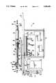
- FIG. 1is a schematic diagram of an apparatus embodying the present invention.
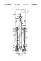
- FIG. 2is front plan view of the pump unit of the apparatus of FIG. 1.
- FIG. 3is a side plan view of the pump unit of FIG. 2.
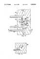
- FIG. 4is a magnified, partial schematic view of the sensing chamber of the apparatus of FIG. 1 illustrating schematically the flow of the sheath fluids and of the sample stream.
- FIG. 5is a partial detailed cross-sectional view of the sensing chamber of FIG. 1.
- FIG. 6is a cross-sectional view of FIG. 5 taken along the line 6--6 of FIG. 5.
- an apparatus embodying the present inventionis indicated generally by the reference numeral 10.
- the apparatus 10is employed for hematological testing, and is specifically suited for cell analysis on a wide variety of species.
- the apparatus 10includes a sample probe 12 for aspirating a sample of blood to be tested.
- the sample probe 12is coupled to a valve matrix 14, which in turn couples the sample probe to a selected syringe within a pump unit 16 to aspirate a predetermined volume of the blood sample into the probe (e.g., 20 ⁇ l), as is described further below.
- the blood sampleis discharged into a mixing cuvette 13, in which a predetermined volume of diluent and a predetermined volume of lyric reagents are rapidly admixed with the whole blood sample.
- the mixing cuvette 13is coupled through the valve matrix 14 and the pump unit 16 to a first chamber or container 18 containing a first lysing agent A, and a second chamber or container 19 containing a second lysing agent B.
- the sample probe 12is also coupled through the valve matrix 14 and pump unit 16 to a diluent reservoir or container 17.
- the sample probe 12dispenses the blood sample along with a predetermined volume of diluent from the diluent reservoir 17 into the mixing cuvette 13.
- predetermined volumes of lysing agent A and/or lysing agent Bare aspirated from the lysing chambers 18 and 19, respectively, by the pump unit 16, and injected through the valve matrix 14 into the mixing cuvette 13, along with the blood sample and diluent to formulate the sample blood/reagent mixture, as described further below.
- the ratio of the individual lyse components in the lytic reagent compositionare present in a ratio and quantity sufficient to effect at least a component separation of white blood cells, so that they can be differentiated, and at least one of the white blood cell subpopulations can be quantified.
- the sample blood/reagent mixtureremains in the mixing cuvette 13 for a short but sufficient amount of time for the red blood cells to be stromatolyzed and to release their hemoglobin, and for the active lytic reagents to act on the cell membranes of the white blood cells and cause them to selectively separate. After this short time period (e.g., approximately 10 to 30 seconds), the sample is aspirated through the valve matrix 14 into a selected syringe in the pump unit 16, as is described further below.
- the sampleis then injected by the pump unit 16 back through the valve matrix 14 and into a sensing chamber 20 (also referred "focused flow" cell) along with a diluent sheath, in which the white blood cells are counted and the volume (size) and/or opacity is measured by electrical or optical differences.
- the white blood cellsare counted for a period of time to gather sufficient data for analysis, typically about 10,000 cells.
- Data pointsare stored and analyzed in a processing and control unit 22, and the data can in turn be visually displayed on a display unit 24.
- a keyboard unit 25is coupled to the processing and control unit 22 to control its operation. After the sample is analyzed, it is passed through the valve matrix 14 into a waste container 26 and discarded.
- the pump unit 16is illustrated in further detail, and includes a first syringe 28, a second syringe 30, and a third syringe 32.
- Each of the syringeshas a piston, and functions as a positive-displacement pump, which can be coupled through the valve matrix 14 to any of the other fluid-containing components of the apparatus 10 in order to aspirate and/or inject the fluids, as is described further below.
- first syringe 28is mounted to a base plate 34 by a first base mount 36, and a first piston 38 of the first syringe is mounted on the other end to a drive plate 40 by a first drive mount 42.
- first piston 38 of the first syringeis mounted on the other end to a drive plate 40 by a first drive mount 42.
- second syringe 30is mounted to the base plate 34 by a second base mount 44, and a second piston 46 of the second syringe is coupled on the other end to the drive plate 40 by a second drive mount 48.
- the third syringe 32is mounted in the opposite direction of the first and second syringes, 28 and 30, respectively.
- a piston 50 of the third syringe 32is coupled on one end to the drive plate 40 by a third drive mount 52, and the other end of the third syringe is coupled to the base plate 34 by a third base mount 54.
- the first syringe 28is coupled to one end of a first line 56 and coupled to one end of a second line 58 by means of a first connector 60.
- the other end of each of the first line 56 and second line 58(not shown) is coupled to the valve matrix 14.
- the second syringe 30likewise is coupled to one end of a first line 62 and coupled to one end of a second line 64 by means of a second connector 66.
- the other end of each of the first line 62 and second line 64(not shown) is coupled to the valve matrix 14.
- Each of the second lines 58 and 64are typically used for injecting and/or aspirating fluids with the respective syringe, whereas the first lines 56 and 62 are typically used for purposes of flushing diluent from the diluent reservoir 17 to clean the respective syringe and/or to wash away any air bubbles.
- the third syringe 32is coupled to one end of a third line 68 for aspirating and/or injecting fluid with the third syringe.
- the other end of the third line 68(not shown) is coupled to the valve matrix 14 for controlling flow through the third line.
- a motor 70is coupled to the drive plate 40 to precisely move the drive plate, and in turn simultaneously control the actuation of the three syringes.
- the motor 70is preferably an electric stepping motor, but may be a DC or AC electric motor with proper feedback and electronic control, and is coupled to a control board 72, which is in turn coupled to the processing and control unit 22 to control the operation of the motor.
- the motor 70comprises a drive shaft 74 coupled to one side of a drive belt 76, which is in turn coupled to one end of a threaded shaft 78 by means of a gear 80.
- the drive belt 76preferably defines a plurality of teeth on its inside surface which mesh with corresponding teeth on both the drive shaft 74 and the gear 80 in order to maintain precise control over the movement of these components.
- the drive shaft 78is mounted on each end by bearing blocks 82 to the base plate 34, and a drive block 84 is mounted on the threaded shaft 78.
- the drive block 84includes an aperture 86 extending through the drive block and defined by a threaded surface 88, which engages the corresponding threads on the threaded shaft 78.
- the drive plate 40is coupled to the drive block 84 by drive mounts 90, which extend through an elongated aperture 92 defined within the base plate 34, indicated in dashed lines in FIG. 3. As can be seen, the elongated aperture 92 extends in a direction substantially parallel to the threaded shaft 78.
- the threaded shaft 78is rotated to drive the drive block 84 along the axis of the threaded shaft 78 by engagement of the threads on the surface 88 with the threads on the shaft 78, which in turn simultaneously moves the drive plate 40 and the pistons of the three syringes.
- the first and second syringes 28 and 30, respectivelyinject, and the third syringe 32 simultaneously aspirates, or vice-versa.
- the pump unit 16further includes a sensor mounted adjacent the threaded shaft 78 and drive block 80 to indicate the position of the drive block and control the operation of the motor 70 in response.
- the sensoris mounted on a sensor control board 93, which is coupled to the drive control board 72 to transmit signals to the drive control board for controlling the operation of the motor 70.
- the drive control board 72is in turn coupled to the processing and control unit 22.
- the sensorincludes three position sensors, a home-position sensor 94, a first-end position sensor 96, and a second-end position sensor 98.
- the drive block 84includes a corresponding sensor plate or flag 100 mounted in line with the three position sensors, and adapted to cause each position sensor to generate a signal when the sensor plate is aligned with a respective position sensor.
- the home-position sensor 100transmits a signal indicative of this condition to the control board 72.
- the processing and control unit 22is responsive to this signal to recognize that both the first and second syringes are nearly empty, and the third syringe is nearly full.
- the processing and control unit 22can cause a precise volume of fluid to either be injected or aspirated with each syringe.
- the first-position sensor 96 and second-position sensor 98are provided as a safety back-up, each being located at one extreme of the permissible movement of the drive block 84. If either of these position sensors are activated, the drive control board 72 is responsive to stop the motor 70 to prevent any damage to the pump unit 16.
- the sensing chamber 20includes a sensing zone 102, which defines a counting orifice 104, as shown in FIG. 4.
- the counting orifice 104receives a narrow stream of the blood sample injected by one of the syringes of the pump unit 16 through the valve matrix 14 and a sample tube 106.
- the sample tube 106is substantially coaxial with the counting orifice 104 and injects a narrow stream of the blood sample through the center of the orifice, as illustrated in FIG. 4.
- the sensing zonecomprises a transducer (not shown) for detecting differences in electrical, optical, chemical or other characteristics in each of the cells of the sample, and for generating a signal whose characteristics relate to such differences. These signals are transmitted to the processing and control unit 22 where they are processed to determine the parameters of the constituent subpopulations of the sample.
- the sensing chamber 20includes a sensing unit 101, which defines a substantially conical-shaped surface 108 for receiving a sheath of diluent surrounding the sample stream injected by the sample tube 106.
- the sensing unit 101is mounted by means of a pair of o-rings 103 within a support block 105.
- the support block 105defines a generally cylindrical chamber A coupled in fluid communication, and substantially concentric with the conical-shaped surface 108.
- the sample tube 106is mounted within the center of the chamber A and extends into the recess defined by the conical-shaped surface 108.
- a first sheath or diluent tube 110is coupled on one end to the chamber A, and in the embodiment of the present invention illustrated, is oriented substantially along a tangent to the cylindrical surface defining the chamber A, as shown in FIG. 6.
- the other end of the first sheath tube 110is coupled through the valve matrix 14 to another of the syringes in the pump unit 16, for receiving a predetermined volume of diluent injected by that syringe.
- the first sheath tube 110is oriented on a tangent to the cylindrical surface of the chamber A, the diluent follows a generally spiral or helical path through the chamber A, along the conical-shaped surface 108, and through the counting orifice 104 surrounding the sample stream, as indicated by the arrows in FIG. 4.
- This particular orientation of the first sheath tube 110is only exemplary, however.
- one or more first sheath tubesmay equally be oriented so that the diluent flows straight along the conical-shaped surface 108 and through the counting orifice 104.
- the sensing unit 101defines a tapered surface 111 on the exit side of the counting orifice 104, which is coupled in fluid communication with a chamber B for receiving the sample stream and diluent injected through the counting orifice.
- An exit tube 112is coupled on one end to the chamber B, and is coupled on the other end (not shown) through the valve matrix 14 to a selected syringe of the pump unit 16 to aspirate the sample/diluent mixture injected through the counting orifice 104 into the chamber B and exit tube 112, into the respective syringe.
- a second sheath tube 114is coupled on one end in fluid communication with the chamber B between the o-ring 103 and the exit tube 112.
- the second sheath tube 114is oriented substantially on a tangent to the cylindrical surface defining the chamber B so that the diluent is aspirated into the chamber B and exit tube 112 along a substantially spiral or helical path surrounding the sample stream injected through the counting orifice 104.
- this particular configuration of the second sheath tube 114is only exemplary, however.
- the other end of the sheath tube 114is coupled through the valve matrix 14 to the diluent reservoir 17.
- a third diluent tube 115is coupled to the chamber A between the o-ring 103 and the first diluent tube 110, and is likewise oriented along a tangent to the cylindrical surface defining the chamber A.
- the other end of the third diluent tube 115is coupled through the valve matrix 14 to the diluent reservoir (or syringe) for flushing the sensing chamber 20 with fresh diluent after running a sample.
- a whole blood sampleis introduced into the sample probe 12.
- the processing and control unit 22connects the sample probe 12 to a selected syringe of the pump unit 16 through the valve matrix 14, and then controls the motor 70 to aspirate a predetermined volume of the whole blood sample (e.g., 20 ⁇ l) through the probe.
- the processing and control unit 22also connects the same syringe through the valve matrix 14 to the diluent reservoir 17, and controls the motor 70 to aspirate a predetermined volume of diluent into the whole blood sample.
- the processing and control unit 22then controls the motor 70 to inject the sample/diluent mixture from the syringe through the valve matrix 14 into the mixing cuvette 13.
- the processing and control unit 22has in a database information as to the predetermined volumes of lysing agent A and lysing agent B necessary to form the proper sample blood/reagent mixture for selected animal species (e.g., dog, cat, rat, mouse, horse, cow, rabbit, monkey, pig, goat, bird, etc.).
- selected animal speciese.g., dog, cat, rat, mouse, horse, cow, rabbit, monkey, pig, goat, bird, etc.
- the operatorinputs through the keyboard unit 25 the particular animal species of the blood sample, and the processing and control unit 22 is responsive to this input based on the information in its database to select a predetermined volume of lysing agent A and a predetermined volume of lysing agent B.
- the processing and control unit 22then connects a selected syringe in the pump unit 16 to the lysing agent A chamber 18 through the valve matrix 14, and controls the motor 70 (by counting a predetermined number of steps) to aspirate the predetermined volume of lysing agent A by the syringe.
- the processing and control unit 22then connects the same syringe (or another syringe) to the lysing agent B chamber 19 through the valve matrix 14, and controls the motor 70 (by counting a predetermined number of steps) to aspirate the predetermined volume of lysing agent B by the syringe.
- the processing and control unit 22then couples the syringe through the valve matrix 14 to the mixing cuvette 13, and controls the motor 70 to inject the predetermined mixture of lysing agent A and lysing agent B into the mixing cuvette with the blood/diluent mixture.
- the processing and control unit 22couples the second line 58 of the first syringe 28 in fluid communication with the mixing cuvette 13 by actuating a valve (not shown) in the valve matrix 14 to aspirate a predetermined volume of sample blood/reagent mixture into the first syringe.
- the volume of the first syringe 28is 250 ⁇ l.
- the processing and control unit 22also couples the second inlet line 62 of the second syringe 30 in fluid communication with the diluent reservoir 17 by actuating a valve (not shown) in the valve matrix 14, to aspirate a predetermined volume of diluent into the second syringe.
- the volume of the second syringe 30is approximately 250 ⁇ l.
- the precise volume of fluid aspirated into each syringeis controlled by the processing and control unit 22, which counts the number of steps of the motor 70 with respect to the home position as indicated by the home-position sensor 94, wherein each step corresponds to a precise volume of fluid for each syringe.
- valves permitting this aspiration of the first and second syringes 28 and 30, respectively,are then closed, and the processing and control unit 22 actuates additional valves in the valve matrix 14 to couple the second line 58 of the first syringe 28 in fluid communication with the sample tube 106 of the sensing chamber 20, and to couple the second line 64 of the second syringe 30 in fluid communication with the first diluent tube 110 of the sensing chamber 20.
- the processing and control unit 22also then actuates selected valves of the valve matrix 14 to couple the third line 68 of the third syringe 32 in fluid communication with the exit tube 112 of the sensing chamber 20, and to couple the second diluent tube 114 in fluid communication with the diluent reservoir 17.
- the systemis then ready to analyze the sample.
- the processing and control unit 22then actuates the motor 70 to drive the drive block 84 back toward the home position. This in turn causes the first and second syringes 28 and 30, respectively, to simultaneously inject the sample blood/reagent mixture through the sample tube 106 and the diluent through the first diluent tube 110. As illustrated in FIG.
- a narrow stream of blood/reagent mixtureis thus injected by the first syringe 28 through the center of the counting orifice 104, and a stream of diluent is injected by the second syringe 30 into the chamber A, along the substantially conical-shaped surface 108, and through the counting orifice 104 along a path which surrounds the stream of sample blood/reagent mixture, but substantially avoids any intermixing of the two streams.
- the counting orificeis approximately 60 microns in diameter
- the sample streamis approximately 15 microns in diameter
- the sheath of diluentis therefore approximately 35 microns thick within the counting orifice, surrounding the sample stream.
- both the flow of the diluent sheath injected through the first diluent tube 110is substantially laminar, and the sample stream injected through the sample tube 106 is substantially laminar, there is substantially no intermixing of the two streams.
- the steady state flow generated by the syringessignificantly facilitates in producing a substantially laminar flow.
- the sample streamis located in the approximate center of both the recess defined by the conical-shaped surface 108 and the counting orifice 104, it moves at a relatively faster velocity through the counting orifice than does the surrounding sheath of diluent, thus further preventing any intermixing of the sample and diluent.
- the sheath of diluentwhich in the embodiment of the present invention illustrated follows a generally spiral or helical path as it is injected through the first diluent tube 110, the chamber A, and along the conical-shaped surface 108, surrounds the sample stream with a substantially laminar flow, and thus tends to maintain the sample flow in a fine, substantially uniform stream located in the center of the counting orifice.
- the flow of the diluent sheathalso tends to maintain the sample stream within the center of the counting orifice.
- the third syringe 32simultaneously aspirates the sample/diluent mixture injected into the outlet side of the counting orifice 104, and also aspirates a second sheath of diluent through the second diluent tube 114 into the exit tube 112. Because the second diluent tube 114 is oriented along a tangent to the surface defining the chamber B, the second sheath of diluent follows a substantially spiral flow path surrounding the sample stream exiting the counting orifice 104. The substantially laminar flow of the second sheath acts to further maintain the sample in a fine, narrow stream as it exits the counting orifice, thus further increasing the ability of the sensing chamber to accurately analyze the sample cells.
- the processing and control unit 22stops the motor 70 after a predetermined volume of the blood sample has been injected by the first syringe 28.
- the volume of the third syringe 32is approximately 5 ml, which is sufficient to receive the entire volume of fluid injected by both the first and second syringes 28 and 30, respectively, and to aspirate a sufficient volume of diluent through the second diluent tube 114 to form the second diluent sheath in the exit tube 112.
- the processing and control unit 22then actuates a selected valve in the valve matrix 14 to couple the third line 68 of the third syringe 32 in fluid communication with the waste reservoir 26, and the motor 70 is then actuated in the opposite direction (i.e., away from the home position) to expel the sample/diluent mixture in the third syringe into the waste reservoir 26.
- One advantage of the present inventionis that because the three syringes are simultaneously driven by the stepping motor, there is a simultaneous, steady-state flow of both the sample and diluent through the counting orifice.
- the smooth and precise operation of the stepping motor in combination with the direct drive of the threaded shaft and drive plate and the positive-displacement pumping of the syringespermits precise, simultaneous control of the fluid flow through the sensing chamber.
- the flow of both diluent sheaths and the sample streamis substantially laminar, thus substantially preventing any mixing of these fluids within the counting orifice.
- the first sheath of diluentcan be injected, or aspirated, along a substantially spiral path through the counting orifice and surrounding the sample stream (which can be aspirated or injected), which also facilitates in maintaining a fine, narrow sample stream, or focused flow of the sample through the counting orifice.
- the second sheath of diluentwhich is likewise substantially laminar, and can be injected or aspirated along a substantially spiral path surrounding the sample stream, further contributes to maintaining a fine, narrow sample stream as the sample exits the counting orifice.
- the anomalies or aberrant information normally associated with coincidence, or with systems which do not provide focused flow,are substantially avoided.
- substantially each cell in the sampleis detected (due to the substantially single file relationship of the cells), important information is not rejected, enabling the system to provide a more true measurement of the cell distribution within each sample.
- Another advantage of the embodiment of the present invention illustratedis that because only one drive has to be used to simultaneously drive all three syringes, which then assures that all three syringes move simultaneously. Also, there is a significant cost savings as opposed to a system in which a separate drive may be employed for each syringe.
- Yet another advantage of the embodiment of the present invention illustratedis that because the sample and sheath are injected through the inlet side of the counting orifice (as opposed to either being pulled or aspirated only through the orifice), deformation of the cells as they flow through the orifice is substantially avoided. Cell distortion is therefore reduced to a minimum, further enhancing the accuracy of the system and providing hematocrit measurements that accurately correlate with spun hematocrits.
- the three syringescan be employed to inject and/or aspirate different fluids simply by adjusting the connections with the syringes in the valve matrix.
- the first diluent sheathis aspirated through the counting orifice by the third syringe 32, whereas the sample stream and the second sheath are injected by the first and second syringes, respectively.
- the third syringe 30may be mounted in the same direction and in the same fashion to the drive plate 40 and base plate 34 as are the first and second syringes 28 and 30, respectively.
- the first syringe 28may inject the sample
- the second syringe 30may inject the first diluent sheath
- the third syringe 32may inject the second diluent sheath.
- the exit tube 112would be coupled in fluid communication with the waste reservoir 26 in order to release the sample/diluent mixture directly into the waste reservoir.
- Another advantage of the present inventionis that the steady state, focused flow produced by the syringes minimizes protein build-up and clogging.
- the first and second diluent sheaths maintained around the sample cellsprevents contact of the sample cells with the walls of both the sensing chamber and the exit tube.
- the sample blood/reagent mixtureis powerfully injected through the counting orifice by one of the syringes, clogs and build-up within each cycle are prevented.
- the processing and control unitcan automatically optimize sample analysis on a species-by-species basis.
- the database of the processing and control unitcan contain information on the predetermined volumes of the lysing agents for all species encountered in this type of hematology system.
- the operatordoes not need to be concerned with preparing the specific blood/reagent mixture for each type of species being tested. Rather, the operator simply inputs the type of species on the keyboard unit, and the processing and control unit automatically determines the quantities of the lysing agents based on the type of species, and then automatically controls the operation of the pump unit to aspirate the predetermined volumes of lysing agents, and to mix them with the sample/diluent mixture in the mixing cuvette.
- the keyboard unit 25has separate keys for certain species (e.g., cat and dog) and another key for other species.
- the processing and control unitautomatically causes the preparation of the blood/reagent mixture for the respective species.
- the display unitdisplays the additional species may be processed. Once the correct species is selected, the processing and control unit automatically causes the preparation of the blood/reagent mixture for the respective species.
- Another advantage of the present inventionis the flexibility of the system to adapt to automatically analyze samples from numerous types of species, and to optimize any cycle for a given species.
- the lyse volumes, the volume of diluent, and the volume of the whole blood samplecan be easily adjusted simply by controlling the processing and control unit. This can be extremely beneficial for analyzing species that are very different, such as mammalian vs. non-mammalian.
- the pump unitemploys several different syringes to aspirate and/or inject these fluids, the apparatus can automatically mix two or more of these fluids in predetermined volumes, which are precisely measured by monitoring operation of the stepping motor, which is a significant advantage over prior hematology systems.
- the volume of lyse A and/or the volume of lyse B (and other lyse agents may be added if necessary)can be automatically adjusted and mixed with the blood/diluent mixture in the mixing cuvette to effect proper separation of blood cells on a species-by-species basis.
- This means for variably adjusting the volume of lytic agentsis significant in obtaining the proper separation of the white blood cell populations.
Landscapes
- Physics & Mathematics (AREA)
- Health & Medical Sciences (AREA)
- Life Sciences & Earth Sciences (AREA)
- Chemical & Material Sciences (AREA)
- Analytical Chemistry (AREA)
- Biochemistry (AREA)
- General Health & Medical Sciences (AREA)
- General Physics & Mathematics (AREA)
- Immunology (AREA)
- Pathology (AREA)
- Investigating Or Analysing Biological Materials (AREA)
Abstract
Description
Claims (34)
Priority Applications (5)
| Application Number | Priority Date | Filing Date | Title |
|---|---|---|---|
| US08/007,111US5380491A (en) | 1993-01-21 | 1993-01-21 | Apparatus for pumping and directing fluids for hematology testing |
| PCT/US1994/014372WO1996007903A1 (en) | 1993-01-21 | 1994-09-06 | Apparatus for pumping and directing fluids for hematology testing |
| US08/370,023US5728351A (en) | 1993-01-21 | 1995-01-09 | Apparatus for making a plurality of reagent mixtures and analyzing particle distributions of the reagent mixtures |
| US09/039,789US6812032B1 (en) | 1993-01-21 | 1998-03-16 | Apparatus and method for making a plurality of reagent mixtures and analyzing particle distributions of the reagent mixtures |
| US10/975,189US7294307B2 (en) | 1993-01-21 | 2004-10-27 | Apparatus for pumping and directing fluids for hematology testing |
Applications Claiming Priority (2)
| Application Number | Priority Date | Filing Date | Title |
|---|---|---|---|
| US08/007,111US5380491A (en) | 1993-01-21 | 1993-01-21 | Apparatus for pumping and directing fluids for hematology testing |
| PCT/US1994/014372WO1996007903A1 (en) | 1993-01-21 | 1994-09-06 | Apparatus for pumping and directing fluids for hematology testing |
Related Child Applications (1)
| Application Number | Title | Priority Date | Filing Date |
|---|---|---|---|
| US08/370,023DivisionUS5728351A (en) | 1993-01-21 | 1995-01-09 | Apparatus for making a plurality of reagent mixtures and analyzing particle distributions of the reagent mixtures |
Publications (1)
| Publication Number | Publication Date |
|---|---|
| US5380491Atrue US5380491A (en) | 1995-01-10 |
Family
ID=26676528
Family Applications (1)
| Application Number | Title | Priority Date | Filing Date |
|---|---|---|---|
| US08/007,111Expired - LifetimeUS5380491A (en) | 1993-01-21 | 1993-01-21 | Apparatus for pumping and directing fluids for hematology testing |
Country Status (2)
| Country | Link |
|---|---|
| US (1) | US5380491A (en) |
| WO (1) | WO1996007903A1 (en) |
Cited By (52)
| Publication number | Priority date | Publication date | Assignee | Title |
|---|---|---|---|---|
| WO1996007903A1 (en)* | 1993-01-21 | 1996-03-14 | Cdc Technologies, Inc. | Apparatus for pumping and directing fluids for hematology testing |
| USRE36074E (en)* | 1990-11-30 | 1999-02-02 | Toa Medical Electronics Co., Ltd. | Particle detector and particle detecting apparatus having the detector |
| US5907240A (en)* | 1997-05-12 | 1999-05-25 | Cdc Technologies, Inc. | Method and apparatus for cell differentiation by measuring apparent cell size, membrane integrity and intracellular complexity |
| US6106778A (en)* | 1997-09-27 | 2000-08-22 | Horiba, Ltd. | Blood cell count/immunoassay apparatus using whole blood |
| US6235002B1 (en) | 1998-04-17 | 2001-05-22 | Cdc Technologies, Inc. | Syringe for use in fluid-handling apparatus |
| US20020034824A1 (en)* | 2000-09-18 | 2002-03-21 | Mitsuru Abo | Blood cell detector, blood analyzer and blood analyzing method using the detector |
| US6391263B1 (en)* | 1999-02-26 | 2002-05-21 | Sysmex Corporation | Automated analyzing system and method therefor |
| US20020091571A1 (en)* | 2000-11-10 | 2002-07-11 | Thomas Nicholas A. | Methods and systems for electronic coupon issuance transmission and mangement |
| US6555065B1 (en)* | 1997-11-19 | 2003-04-29 | Francois Melet | Automatic hematologic counting and analysing device |
| US6979569B1 (en)* | 1995-06-02 | 2005-12-27 | Cdc Technologies, Inc. | Apparatus and method for mixing fluids for analysis |
| US20060020191A1 (en)* | 2004-07-13 | 2006-01-26 | Dexcom, Inc. | Transcutaneous analyte sensor |
| US20080194938A1 (en)* | 2004-07-13 | 2008-08-14 | Dexcom, Inc. | Transcutaneous medical device with variable stiffness |
| US20080197024A1 (en)* | 2003-12-05 | 2008-08-21 | Dexcom, Inc. | Analyte sensor |
| US20090035873A1 (en)* | 2007-07-31 | 2009-02-05 | Sysmex Corporation | Sample analyzer, sample analyzing method, and computer program product |
| US20090124964A1 (en)* | 2003-12-05 | 2009-05-14 | Dexcom, Inc. | Integrated device for continuous in vivo analyte detection and simultaneous control of an infusion device |
| US20090131776A1 (en)* | 2006-10-04 | 2009-05-21 | Dexcom, Inc. | Analyte sensor |
| US20090131768A1 (en)* | 2006-10-04 | 2009-05-21 | Dexcom, Inc. | Analyte sensor |
| US20090131777A1 (en)* | 2006-10-04 | 2009-05-21 | Dexcom, Inc. | Analyte sensor |
| US20090131769A1 (en)* | 2006-10-04 | 2009-05-21 | Dexcom, Inc. | Analyte sensor |
| US20090137887A1 (en)* | 2006-10-04 | 2009-05-28 | Dexcom, Inc. | Analyte sensor |
| US20090143659A1 (en)* | 2003-08-01 | 2009-06-04 | Dexcom, Inc. | Analyte sensor |
| US20090178459A1 (en)* | 2003-08-01 | 2009-07-16 | Dexcom, Inc. | Analyte sensor |
| US20090182217A1 (en)* | 2003-12-05 | 2009-07-16 | Dexcom, Inc. | Analyte sensor |
| US20090242425A1 (en)* | 2008-03-25 | 2009-10-01 | Dexcom, Inc. | Analyte sensor |
| US7615007B2 (en) | 2006-10-04 | 2009-11-10 | Dexcom, Inc. | Analyte sensor |
| US7640048B2 (en) | 2004-07-13 | 2009-12-29 | Dexcom, Inc. | Analyte sensor |
| US20100231904A1 (en)* | 2009-03-12 | 2010-09-16 | Tyrie Colin C | Method and Device for Measuring Hydrocarbons in Aqueous Solutions |
| WO2012120506A2 (en) | 2011-03-09 | 2012-09-13 | Pixcell Medical Technologies Ltd. | Disposable cartridge for preparing a sample fluid containing cells for analysis |
| US8364231B2 (en) | 2006-10-04 | 2013-01-29 | Dexcom, Inc. | Analyte sensor |
| US8364230B2 (en) | 2006-10-04 | 2013-01-29 | Dexcom, Inc. | Analyte sensor |
| US8425416B2 (en) | 2006-10-04 | 2013-04-23 | Dexcom, Inc. | Analyte sensor |
| US8447376B2 (en) | 2006-10-04 | 2013-05-21 | Dexcom, Inc. | Analyte sensor |
| US8562558B2 (en) | 2007-06-08 | 2013-10-22 | Dexcom, Inc. | Integrated medicament delivery device for use with continuous analyte sensor |
| US20150338424A1 (en)* | 2012-12-27 | 2015-11-26 | Korea University Research And Business Foundation | Apparatus and method for platelet function and drug repsonse testing based on microfluidic chip |
| US9863837B2 (en) | 2013-12-18 | 2018-01-09 | OptiScan Biomedical Coporation | Systems and methods for detecting leaks |
| US9986942B2 (en) | 2004-07-13 | 2018-06-05 | Dexcom, Inc. | Analyte sensor |
| WO2018237246A1 (en)* | 2017-06-23 | 2018-12-27 | Arizona Board Of Regents On Behalf Of The University Of Arizona | SYSTEMS AND METHODS FOR PLATLETARY FUNCTION ANALYSIS |
| US10610136B2 (en) | 2005-03-10 | 2020-04-07 | Dexcom, Inc. | System and methods for processing analyte sensor data for sensor calibration |
| US10813577B2 (en) | 2005-06-21 | 2020-10-27 | Dexcom, Inc. | Analyte sensor |
| US10835672B2 (en) | 2004-02-26 | 2020-11-17 | Dexcom, Inc. | Integrated insulin delivery system with continuous glucose sensor |
| US10966609B2 (en) | 2004-02-26 | 2021-04-06 | Dexcom, Inc. | Integrated medicament delivery device for use with continuous analyte sensor |
| US10980461B2 (en) | 2008-11-07 | 2021-04-20 | Dexcom, Inc. | Advanced analyte sensor calibration and error detection |
| US11000215B1 (en) | 2003-12-05 | 2021-05-11 | Dexcom, Inc. | Analyte sensor |
| US11246990B2 (en) | 2004-02-26 | 2022-02-15 | Dexcom, Inc. | Integrated delivery device for continuous glucose sensor |
| US11331022B2 (en) | 2017-10-24 | 2022-05-17 | Dexcom, Inc. | Pre-connected analyte sensors |
| US11350862B2 (en) | 2017-10-24 | 2022-06-07 | Dexcom, Inc. | Pre-connected analyte sensors |
| US11358148B2 (en) | 2018-03-30 | 2022-06-14 | Idexx Laboratories, Inc. | Point-of-care diagnostic systems and containers for same |
| US11399745B2 (en) | 2006-10-04 | 2022-08-02 | Dexcom, Inc. | Dual electrode system for a continuous analyte sensor |
| CN114878846A (en)* | 2022-07-08 | 2022-08-09 | 深圳市帝迈生物技术有限公司 | Blood analyzer and cleaning method thereof |
| US11441997B2 (en) | 2018-03-30 | 2022-09-13 | Idexx Laboratories, Inc. | Quality control for point-of-care diagnostic systems |
| US11541396B2 (en) | 2018-03-30 | 2023-01-03 | Idexx Laboratories, Inc. | Point-of-care diagnostic systems and containers for same |
| US11633133B2 (en) | 2003-12-05 | 2023-04-25 | Dexcom, Inc. | Dual electrode system for a continuous analyte sensor |
Citations (25)
| Publication number | Priority date | Publication date | Assignee | Title |
|---|---|---|---|---|
| US3793587A (en)* | 1971-03-10 | 1974-02-19 | Licentia Gmbh | Particle volume and cross-section measurement |
| US3810010A (en)* | 1968-11-02 | 1974-05-07 | Telefunken Patent | Particle analysis method and apparatus wherein liquid containing particles is sucked into a constricted flow path |
| US3871770A (en)* | 1973-06-04 | 1975-03-18 | Nuclear Data Inc | Hydrodynamic focusing method and apparatus |
| US3900290A (en)* | 1973-03-13 | 1975-08-19 | Int Octrooi Mij Octropa Nl1973 | Method and apparatus for determining the degree of platelet aggregation in blood |
| US4001678A (en)* | 1974-05-16 | 1977-01-04 | Berg Robert H | Displacement metering with independent ancillary flow |
| US4014611A (en)* | 1975-04-30 | 1977-03-29 | Coulter Electronics, Inc. | Aperture module for use in particle testing apparatus |
| US4050904A (en)* | 1974-10-07 | 1977-09-27 | Clean Energy Corporation | Solubilization and reaction of coal and like carbonaceous feedstocks to hydrocarbons and apparatus therefor |
| US4165484A (en)* | 1977-03-23 | 1979-08-21 | Becton, Dickinson And Company | Particle counting apparatus utilizing various fluid resistors to maintain proper pressure differentials |
| US4198160A (en)* | 1976-12-14 | 1980-04-15 | Max-Planck-Gesellschaft Zur Forderung Der Wissenschaften E.V. | Apparatus for performing at least two measurements of characteristics in a particle suspension |
| US4253058A (en)* | 1977-11-11 | 1981-02-24 | Max-Planck-Gesellschaft Zur Foerderung Der Wissenschaften E.V. | Device for measuring certain properties of particles suspended in a particle suspension |
| US4395676A (en)* | 1980-11-24 | 1983-07-26 | Coulter Electronics, Inc. | Focused aperture module |
| US4420564A (en)* | 1980-11-21 | 1983-12-13 | Fuji Electric Company, Ltd. | Blood sugar analyzer having fixed enzyme membrane sensor |
| US4424276A (en)* | 1981-12-07 | 1984-01-03 | Intermountain Health Care | Method and apparatus for measuring the gaseous content of blood |
| EP0101161A2 (en)* | 1982-08-16 | 1984-02-22 | TECHNICON INSTRUMENTS CORPORATION (a New York corporation) | Apparatus and method for passing two fluids simultaneously through an analytical flow cell |
| EP0107333A2 (en)* | 1982-09-30 | 1984-05-02 | TECHNICON INSTRUMENTS CORPORATION (a New York corporation) | Apparatus and method for supply of sample and sheath liquids to analytical flow cell |
| US4509904A (en)* | 1983-10-04 | 1985-04-09 | Petrophysical Services, Inc. | Metering pump |
| US4634431A (en)* | 1976-11-12 | 1987-01-06 | Whitney Douglass G | Syringe injector |
| US4695431A (en)* | 1982-08-16 | 1987-09-22 | Technicon Instruments Corporation | Volumetric pumping apparatus and method for supplying fluids to sheath stream flow cells |
| US4713974A (en)* | 1986-04-18 | 1987-12-22 | Varian Associates, Inc./Scientific Systems, Inc. | Autosampler |
| WO1989004961A1 (en)* | 1987-11-13 | 1989-06-01 | Techne Corporation | Hematology cell counting apparatus |
| US4908187A (en)* | 1987-04-01 | 1990-03-13 | Endowment For Research In Human Biology, Inc. | Device for diluting and mixing liquids and applications for kinetic analysis |
| US5003895A (en)* | 1988-02-19 | 1991-04-02 | Lev Talanker | Embroidery pantograph assembly |
| US5134079A (en)* | 1989-03-27 | 1992-07-28 | International Technidyne Corp. | Fluid sample collection and delivery system and methods particularly adapted for body fluid sampling |
| US5256374A (en)* | 1990-04-04 | 1993-10-26 | Her Majesty The Queen In Right Of Canada, As Represented By The Minister Of Energy Mines And Resources | Sample introduction for spectrometers |
| US5260027A (en)* | 1991-06-05 | 1993-11-09 | Toa Medical Electronics Co., Ltd. | Method and apparatus for automatically analyzing particles using plural analyzing modules |
Family Cites Families (6)
| Publication number | Priority date | Publication date | Assignee | Title |
|---|---|---|---|---|
| JPS5916667B2 (en)* | 1975-02-28 | 1984-04-17 | トウアイヨウデンシ カブシキガイシヤ | automatic blood analyzer |
| US4503385A (en)* | 1983-07-11 | 1985-03-05 | Becton, Dickinson And Company | Apparatus and method for regulating sheath fluid flow in a hydrodynamically focused fluid flow system |
| US4948565A (en)* | 1989-04-25 | 1990-08-14 | Fisher Scientific Company | Analytical system |
| US5030002A (en)* | 1989-08-11 | 1991-07-09 | Becton, Dickinson And Company | Method and apparatus for sorting particles with a moving catcher tube |
| US5316725A (en)* | 1991-06-07 | 1994-05-31 | Edward Lawrence Carver, Jr. | Reagent system for the improved determination of white blood cell subpopulations |
| US5380491A (en)* | 1993-01-21 | 1995-01-10 | Cdc Technologies, Inc. | Apparatus for pumping and directing fluids for hematology testing |
- 1993
- 1993-01-21USUS08/007,111patent/US5380491A/ennot_activeExpired - Lifetime
- 1994
- 1994-09-06WOPCT/US1994/014372patent/WO1996007903A1/enactiveIP Right Grant
Patent Citations (26)
| Publication number | Priority date | Publication date | Assignee | Title |
|---|---|---|---|---|
| US3810010A (en)* | 1968-11-02 | 1974-05-07 | Telefunken Patent | Particle analysis method and apparatus wherein liquid containing particles is sucked into a constricted flow path |
| US3793587A (en)* | 1971-03-10 | 1974-02-19 | Licentia Gmbh | Particle volume and cross-section measurement |
| US3900290A (en)* | 1973-03-13 | 1975-08-19 | Int Octrooi Mij Octropa Nl1973 | Method and apparatus for determining the degree of platelet aggregation in blood |
| US3871770A (en)* | 1973-06-04 | 1975-03-18 | Nuclear Data Inc | Hydrodynamic focusing method and apparatus |
| US4001678A (en)* | 1974-05-16 | 1977-01-04 | Berg Robert H | Displacement metering with independent ancillary flow |
| US4050904A (en)* | 1974-10-07 | 1977-09-27 | Clean Energy Corporation | Solubilization and reaction of coal and like carbonaceous feedstocks to hydrocarbons and apparatus therefor |
| US4014611A (en)* | 1975-04-30 | 1977-03-29 | Coulter Electronics, Inc. | Aperture module for use in particle testing apparatus |
| US4634431A (en)* | 1976-11-12 | 1987-01-06 | Whitney Douglass G | Syringe injector |
| US4198160A (en)* | 1976-12-14 | 1980-04-15 | Max-Planck-Gesellschaft Zur Forderung Der Wissenschaften E.V. | Apparatus for performing at least two measurements of characteristics in a particle suspension |
| US4165484A (en)* | 1977-03-23 | 1979-08-21 | Becton, Dickinson And Company | Particle counting apparatus utilizing various fluid resistors to maintain proper pressure differentials |
| US4253058A (en)* | 1977-11-11 | 1981-02-24 | Max-Planck-Gesellschaft Zur Foerderung Der Wissenschaften E.V. | Device for measuring certain properties of particles suspended in a particle suspension |
| US4420564A (en)* | 1980-11-21 | 1983-12-13 | Fuji Electric Company, Ltd. | Blood sugar analyzer having fixed enzyme membrane sensor |
| US4395676A (en)* | 1980-11-24 | 1983-07-26 | Coulter Electronics, Inc. | Focused aperture module |
| US4424276A (en)* | 1981-12-07 | 1984-01-03 | Intermountain Health Care | Method and apparatus for measuring the gaseous content of blood |
| EP0101161A2 (en)* | 1982-08-16 | 1984-02-22 | TECHNICON INSTRUMENTS CORPORATION (a New York corporation) | Apparatus and method for passing two fluids simultaneously through an analytical flow cell |
| US4695431A (en)* | 1982-08-16 | 1987-09-22 | Technicon Instruments Corporation | Volumetric pumping apparatus and method for supplying fluids to sheath stream flow cells |
| EP0107333A2 (en)* | 1982-09-30 | 1984-05-02 | TECHNICON INSTRUMENTS CORPORATION (a New York corporation) | Apparatus and method for supply of sample and sheath liquids to analytical flow cell |
| US4683212A (en)* | 1982-09-30 | 1987-07-28 | Technicon Instruments Corporation | Random access single channel sheath stream apparatus |
| US4509904A (en)* | 1983-10-04 | 1985-04-09 | Petrophysical Services, Inc. | Metering pump |
| US4713974A (en)* | 1986-04-18 | 1987-12-22 | Varian Associates, Inc./Scientific Systems, Inc. | Autosampler |
| US4908187A (en)* | 1987-04-01 | 1990-03-13 | Endowment For Research In Human Biology, Inc. | Device for diluting and mixing liquids and applications for kinetic analysis |
| WO1989004961A1 (en)* | 1987-11-13 | 1989-06-01 | Techne Corporation | Hematology cell counting apparatus |
| US5003895A (en)* | 1988-02-19 | 1991-04-02 | Lev Talanker | Embroidery pantograph assembly |
| US5134079A (en)* | 1989-03-27 | 1992-07-28 | International Technidyne Corp. | Fluid sample collection and delivery system and methods particularly adapted for body fluid sampling |
| US5256374A (en)* | 1990-04-04 | 1993-10-26 | Her Majesty The Queen In Right Of Canada, As Represented By The Minister Of Energy Mines And Resources | Sample introduction for spectrometers |
| US5260027A (en)* | 1991-06-05 | 1993-11-09 | Toa Medical Electronics Co., Ltd. | Method and apparatus for automatically analyzing particles using plural analyzing modules |
Non-Patent Citations (2)
| Title |
|---|
| Houwen, "New Approaches To Detect Multiple Red Cell Populations", Loma Linda University Medical Center, (Jul. 31, 1991). |
| Houwen, New Approaches To Detect Multiple Red Cell Populations , Loma Linda University Medical Center, (Jul. 31, 1991).* |
Cited By (145)
| Publication number | Priority date | Publication date | Assignee | Title |
|---|---|---|---|---|
| USRE36074E (en)* | 1990-11-30 | 1999-02-02 | Toa Medical Electronics Co., Ltd. | Particle detector and particle detecting apparatus having the detector |
| WO1996007903A1 (en)* | 1993-01-21 | 1996-03-14 | Cdc Technologies, Inc. | Apparatus for pumping and directing fluids for hematology testing |
| US6979569B1 (en)* | 1995-06-02 | 2005-12-27 | Cdc Technologies, Inc. | Apparatus and method for mixing fluids for analysis |
| EP1005641A4 (en)* | 1997-05-12 | 2002-08-07 | Cdc Technologies Inc | Method/apparatus for cell differentiation measuring cell size, membrane integrity, intracellular complexity |
| US5907240A (en)* | 1997-05-12 | 1999-05-25 | Cdc Technologies, Inc. | Method and apparatus for cell differentiation by measuring apparent cell size, membrane integrity and intracellular complexity |
| US6106778A (en)* | 1997-09-27 | 2000-08-22 | Horiba, Ltd. | Blood cell count/immunoassay apparatus using whole blood |
| US6555065B1 (en)* | 1997-11-19 | 2003-04-29 | Francois Melet | Automatic hematologic counting and analysing device |
| WO1999053973A3 (en)* | 1998-04-17 | 2008-03-20 | Cdc Technologies Inc | Syringe for use in fluid-handling apparatus |
| US6235002B1 (en) | 1998-04-17 | 2001-05-22 | Cdc Technologies, Inc. | Syringe for use in fluid-handling apparatus |
| US6391263B1 (en)* | 1999-02-26 | 2002-05-21 | Sysmex Corporation | Automated analyzing system and method therefor |
| US6716633B2 (en)* | 2000-09-18 | 2004-04-06 | Sysmex Corporation | Blood cell detector, blood analyzer and blood analyzing method using the detector |
| US20020034824A1 (en)* | 2000-09-18 | 2002-03-21 | Mitsuru Abo | Blood cell detector, blood analyzer and blood analyzing method using the detector |
| US20020091571A1 (en)* | 2000-11-10 | 2002-07-11 | Thomas Nicholas A. | Methods and systems for electronic coupon issuance transmission and mangement |
| US10052055B2 (en) | 2003-08-01 | 2018-08-21 | Dexcom, Inc. | Analyte sensor |
| US8886273B2 (en) | 2003-08-01 | 2014-11-11 | Dexcom, Inc. | Analyte sensor |
| US8626257B2 (en) | 2003-08-01 | 2014-01-07 | Dexcom, Inc. | Analyte sensor |
| US20090143659A1 (en)* | 2003-08-01 | 2009-06-04 | Dexcom, Inc. | Analyte sensor |
| US20090178459A1 (en)* | 2003-08-01 | 2009-07-16 | Dexcom, Inc. | Analyte sensor |
| US20080197024A1 (en)* | 2003-12-05 | 2008-08-21 | Dexcom, Inc. | Analyte sensor |
| US8425417B2 (en) | 2003-12-05 | 2013-04-23 | Dexcom, Inc. | Integrated device for continuous in vivo analyte detection and simultaneous control of an infusion device |
| US20090124964A1 (en)* | 2003-12-05 | 2009-05-14 | Dexcom, Inc. | Integrated device for continuous in vivo analyte detection and simultaneous control of an infusion device |
| US8287453B2 (en) | 2003-12-05 | 2012-10-16 | Dexcom, Inc. | Analyte sensor |
| US20090182217A1 (en)* | 2003-12-05 | 2009-07-16 | Dexcom, Inc. | Analyte sensor |
| US11000215B1 (en) | 2003-12-05 | 2021-05-11 | Dexcom, Inc. | Analyte sensor |
| US11633133B2 (en) | 2003-12-05 | 2023-04-25 | Dexcom, Inc. | Dual electrode system for a continuous analyte sensor |
| US11020031B1 (en) | 2003-12-05 | 2021-06-01 | Dexcom, Inc. | Analyte sensor |
| US10835672B2 (en) | 2004-02-26 | 2020-11-17 | Dexcom, Inc. | Integrated insulin delivery system with continuous glucose sensor |
| US11246990B2 (en) | 2004-02-26 | 2022-02-15 | Dexcom, Inc. | Integrated delivery device for continuous glucose sensor |
| US12226617B2 (en) | 2004-02-26 | 2025-02-18 | Dexcom, Inc. | Integrated delivery device for continuous glucose sensor |
| US10966609B2 (en) | 2004-02-26 | 2021-04-06 | Dexcom, Inc. | Integrated medicament delivery device for use with continuous analyte sensor |
| US12115357B2 (en) | 2004-02-26 | 2024-10-15 | Dexcom, Inc. | Integrated delivery device for continuous glucose sensor |
| US12102410B2 (en) | 2004-02-26 | 2024-10-01 | Dexcom, Inc | Integrated medicament delivery device for use with continuous analyte sensor |
| US10799158B2 (en) | 2004-07-13 | 2020-10-13 | Dexcom, Inc. | Analyte sensor |
| US7640048B2 (en) | 2004-07-13 | 2009-12-29 | Dexcom, Inc. | Analyte sensor |
| US7783333B2 (en) | 2004-07-13 | 2010-08-24 | Dexcom, Inc. | Transcutaneous medical device with variable stiffness |
| US11883164B2 (en) | 2004-07-13 | 2024-01-30 | Dexcom, Inc. | System and methods for processing analyte sensor data for sensor calibration |
| US20100081908A1 (en)* | 2004-07-13 | 2010-04-01 | Dexcom, Inc. | Analyte sensor |
| US7857760B2 (en) | 2004-07-13 | 2010-12-28 | Dexcom, Inc. | Analyte sensor |
| US7885697B2 (en) | 2004-07-13 | 2011-02-08 | Dexcom, Inc. | Transcutaneous analyte sensor |
| US10709362B2 (en) | 2004-07-13 | 2020-07-14 | Dexcom, Inc. | Analyte sensor |
| US10993641B2 (en) | 2004-07-13 | 2021-05-04 | Dexcom, Inc. | Analyte sensor |
| US8750955B2 (en) | 2004-07-13 | 2014-06-10 | Dexcom, Inc. | Analyte sensor |
| US20080194938A1 (en)* | 2004-07-13 | 2008-08-14 | Dexcom, Inc. | Transcutaneous medical device with variable stiffness |
| US10980452B2 (en) | 2004-07-13 | 2021-04-20 | Dexcom, Inc. | Analyte sensor |
| US11045120B2 (en) | 2004-07-13 | 2021-06-29 | Dexcom, Inc. | Analyte sensor |
| US10932700B2 (en) | 2004-07-13 | 2021-03-02 | Dexcom, Inc. | Analyte sensor |
| US10524703B2 (en) | 2004-07-13 | 2020-01-07 | Dexcom, Inc. | Transcutaneous analyte sensor |
| US10722152B2 (en) | 2004-07-13 | 2020-07-28 | Dexcom, Inc. | Analyte sensor |
| US20060020191A1 (en)* | 2004-07-13 | 2006-01-26 | Dexcom, Inc. | Transcutaneous analyte sensor |
| US10918313B2 (en) | 2004-07-13 | 2021-02-16 | Dexcom, Inc. | Analyte sensor |
| US10918315B2 (en) | 2004-07-13 | 2021-02-16 | Dexcom, Inc. | Analyte sensor |
| US9986942B2 (en) | 2004-07-13 | 2018-06-05 | Dexcom, Inc. | Analyte sensor |
| US10918314B2 (en) | 2004-07-13 | 2021-02-16 | Dexcom, Inc. | Analyte sensor |
| US11064917B2 (en) | 2004-07-13 | 2021-07-20 | Dexcom, Inc. | Analyte sensor |
| US11026605B1 (en) | 2004-07-13 | 2021-06-08 | Dexcom, Inc. | Analyte sensor |
| US10799159B2 (en) | 2004-07-13 | 2020-10-13 | Dexcom, Inc. | Analyte sensor |
| US10993642B2 (en) | 2004-07-13 | 2021-05-04 | Dexcom, Inc. | Analyte sensor |
| US10813576B2 (en) | 2004-07-13 | 2020-10-27 | Dexcom, Inc. | Analyte sensor |
| US8792953B2 (en) | 2004-07-13 | 2014-07-29 | Dexcom, Inc. | Transcutaneous analyte sensor |
| US8812072B2 (en) | 2004-07-13 | 2014-08-19 | Dexcom, Inc. | Transcutaneous medical device with variable stiffness |
| US20060020186A1 (en)* | 2004-07-13 | 2006-01-26 | Dexcom, Inc. | Transcutaneous analyte sensor |
| US10709363B2 (en) | 2004-07-13 | 2020-07-14 | Dexcom, Inc. | Analyte sensor |
| US10827956B2 (en) | 2004-07-13 | 2020-11-10 | Dexcom, Inc. | Analyte sensor |
| US9414777B2 (en) | 2004-07-13 | 2016-08-16 | Dexcom, Inc. | Transcutaneous analyte sensor |
| US10716498B2 (en) | 2005-03-10 | 2020-07-21 | Dexcom, Inc. | System and methods for processing analyte sensor data for sensor calibration |
| US11051726B2 (en) | 2005-03-10 | 2021-07-06 | Dexcom, Inc. | System and methods for processing analyte sensor data for sensor calibration |
| US10898114B2 (en) | 2005-03-10 | 2021-01-26 | Dexcom, Inc. | System and methods for processing analyte sensor data for sensor calibration |
| US10918316B2 (en) | 2005-03-10 | 2021-02-16 | Dexcom, Inc. | System and methods for processing analyte sensor data for sensor calibration |
| US10918318B2 (en) | 2005-03-10 | 2021-02-16 | Dexcom, Inc. | System and methods for processing analyte sensor data for sensor calibration |
| US10918317B2 (en) | 2005-03-10 | 2021-02-16 | Dexcom, Inc. | System and methods for processing analyte sensor data for sensor calibration |
| US11000213B2 (en) | 2005-03-10 | 2021-05-11 | Dexcom, Inc. | System and methods for processing analyte sensor data for sensor calibration |
| US10743801B2 (en) | 2005-03-10 | 2020-08-18 | Dexcom, Inc. | System and methods for processing analyte sensor data for sensor calibration |
| US10925524B2 (en) | 2005-03-10 | 2021-02-23 | Dexcom, Inc. | System and methods for processing analyte sensor data for sensor calibration |
| US10856787B2 (en) | 2005-03-10 | 2020-12-08 | Dexcom, Inc. | System and methods for processing analyte sensor data for sensor calibration |
| US10709364B2 (en) | 2005-03-10 | 2020-07-14 | Dexcom, Inc. | System and methods for processing analyte sensor data for sensor calibration |
| US10610136B2 (en) | 2005-03-10 | 2020-04-07 | Dexcom, Inc. | System and methods for processing analyte sensor data for sensor calibration |
| US10610137B2 (en) | 2005-03-10 | 2020-04-07 | Dexcom, Inc. | System and methods for processing analyte sensor data for sensor calibration |
| US10610135B2 (en) | 2005-03-10 | 2020-04-07 | Dexcom, Inc. | System and methods for processing analyte sensor data for sensor calibration |
| US10617336B2 (en) | 2005-03-10 | 2020-04-14 | Dexcom, Inc. | System and methods for processing analyte sensor data for sensor calibration |
| US10813577B2 (en) | 2005-06-21 | 2020-10-27 | Dexcom, Inc. | Analyte sensor |
| US20100298684A1 (en)* | 2006-10-04 | 2010-11-25 | Dexcom, Inc. | Analyte sensor |
| US8447376B2 (en) | 2006-10-04 | 2013-05-21 | Dexcom, Inc. | Analyte sensor |
| US7615007B2 (en) | 2006-10-04 | 2009-11-10 | Dexcom, Inc. | Analyte sensor |
| US10349873B2 (en) | 2006-10-04 | 2019-07-16 | Dexcom, Inc. | Analyte sensor |
| US20090287074A1 (en)* | 2006-10-04 | 2009-11-19 | Dexcom, Inc. | Analyte sensor |
| US20100081910A1 (en)* | 2006-10-04 | 2010-04-01 | Dexcom, Inc. | Analyte sensor |
| US20090131776A1 (en)* | 2006-10-04 | 2009-05-21 | Dexcom, Inc. | Analyte sensor |
| US7775975B2 (en) | 2006-10-04 | 2010-08-17 | Dexcom, Inc. | Analyte sensor |
| US9451908B2 (en) | 2006-10-04 | 2016-09-27 | Dexcom, Inc. | Analyte sensor |
| US20090131768A1 (en)* | 2006-10-04 | 2009-05-21 | Dexcom, Inc. | Analyte sensor |
| US8911367B2 (en) | 2006-10-04 | 2014-12-16 | Dexcom, Inc. | Analyte sensor |
| US8774886B2 (en) | 2006-10-04 | 2014-07-08 | Dexcom, Inc. | Analyte sensor |
| US11382539B2 (en) | 2006-10-04 | 2022-07-12 | Dexcom, Inc. | Analyte sensor |
| US8562528B2 (en) | 2006-10-04 | 2013-10-22 | Dexcom, Inc. | Analyte sensor |
| US8532730B2 (en) | 2006-10-04 | 2013-09-10 | Dexcom, Inc. | Analyte sensor |
| US8478377B2 (en) | 2006-10-04 | 2013-07-02 | Dexcom, Inc. | Analyte sensor |
| US8449464B2 (en) | 2006-10-04 | 2013-05-28 | Dexcom, Inc. | Analyte sensor |
| US20090137887A1 (en)* | 2006-10-04 | 2009-05-28 | Dexcom, Inc. | Analyte sensor |
| US8425416B2 (en) | 2006-10-04 | 2013-04-23 | Dexcom, Inc. | Analyte sensor |
| US20090131777A1 (en)* | 2006-10-04 | 2009-05-21 | Dexcom, Inc. | Analyte sensor |
| US8364230B2 (en) | 2006-10-04 | 2013-01-29 | Dexcom, Inc. | Analyte sensor |
| US8364231B2 (en) | 2006-10-04 | 2013-01-29 | Dexcom, Inc. | Analyte sensor |
| US20090131769A1 (en)* | 2006-10-04 | 2009-05-21 | Dexcom, Inc. | Analyte sensor |
| US8298142B2 (en) | 2006-10-04 | 2012-10-30 | Dexcom, Inc. | Analyte sensor |
| US8275438B2 (en) | 2006-10-04 | 2012-09-25 | Dexcom, Inc. | Analyte sensor |
| US11399745B2 (en) | 2006-10-04 | 2022-08-02 | Dexcom, Inc. | Dual electrode system for a continuous analyte sensor |
| US8562558B2 (en) | 2007-06-08 | 2013-10-22 | Dexcom, Inc. | Integrated medicament delivery device for use with continuous analyte sensor |
| US9741139B2 (en) | 2007-06-08 | 2017-08-22 | Dexcom, Inc. | Integrated medicament delivery device for use with continuous analyte sensor |
| US12394120B2 (en) | 2007-06-08 | 2025-08-19 | Dexcom, Inc. | Integrated medicament delivery device for use with continuous analyte sensor |
| US10403012B2 (en) | 2007-06-08 | 2019-09-03 | Dexcom, Inc. | Integrated medicament delivery device for use with continuous analyte sensor |
| US11373347B2 (en) | 2007-06-08 | 2022-06-28 | Dexcom, Inc. | Integrated medicament delivery device for use with continuous analyte sensor |
| US8158439B2 (en)* | 2007-07-31 | 2012-04-17 | Sysmex Corporation | Multiple operating mode sample analyzer, analyzing method, and computer program product |
| US20090035873A1 (en)* | 2007-07-31 | 2009-02-05 | Sysmex Corporation | Sample analyzer, sample analyzing method, and computer program product |
| US11744943B2 (en) | 2007-10-09 | 2023-09-05 | Dexcom, Inc. | Integrated insulin delivery system with continuous glucose sensor |
| US11160926B1 (en) | 2007-10-09 | 2021-11-02 | Dexcom, Inc. | Pre-connected analyte sensors |
| US12397110B2 (en) | 2007-10-09 | 2025-08-26 | Dexcom, Inc. | Integrated insulin delivery system with continuous glucose sensor |
| US12397113B2 (en) | 2007-10-09 | 2025-08-26 | Dexcom, Inc. | Integrated insulin delivery system with continuous glucose sensor |
| US12246166B2 (en) | 2007-10-09 | 2025-03-11 | Dexcom, Inc. | Integrated insulin delivery system with continuous glucose sensor |
| US20090242425A1 (en)* | 2008-03-25 | 2009-10-01 | Dexcom, Inc. | Analyte sensor |
| US11896374B2 (en) | 2008-03-25 | 2024-02-13 | Dexcom, Inc. | Analyte sensor |
| US8396528B2 (en) | 2008-03-25 | 2013-03-12 | Dexcom, Inc. | Analyte sensor |
| US10602968B2 (en) | 2008-03-25 | 2020-03-31 | Dexcom, Inc. | Analyte sensor |
| US10980461B2 (en) | 2008-11-07 | 2021-04-20 | Dexcom, Inc. | Advanced analyte sensor calibration and error detection |
| US20100231904A1 (en)* | 2009-03-12 | 2010-09-16 | Tyrie Colin C | Method and Device for Measuring Hydrocarbons in Aqueous Solutions |
| EP3950136A1 (en) | 2011-03-09 | 2022-02-09 | Pixcell Medical Technologies Ltd. | Disposable cartridge for preparing a sample fluid containing cells for analysis |
| WO2012120506A2 (en) | 2011-03-09 | 2012-09-13 | Pixcell Medical Technologies Ltd. | Disposable cartridge for preparing a sample fluid containing cells for analysis |
| US9983220B2 (en)* | 2012-12-27 | 2018-05-29 | Korea University Research And Business Foundation | Apparatus and method for platelet function and drug response testing based on microfluidic chip |
| US20150338424A1 (en)* | 2012-12-27 | 2015-11-26 | Korea University Research And Business Foundation | Apparatus and method for platelet function and drug repsonse testing based on microfluidic chip |
| US9863837B2 (en) | 2013-12-18 | 2018-01-09 | OptiScan Biomedical Coporation | Systems and methods for detecting leaks |
| US11458470B2 (en) | 2017-06-23 | 2022-10-04 | Arizona Board Of Regents On Behalf Of The University Of Arizona | Systems and methods for analyzing platelet function |
| WO2018237246A1 (en)* | 2017-06-23 | 2018-12-27 | Arizona Board Of Regents On Behalf Of The University Of Arizona | SYSTEMS AND METHODS FOR PLATLETARY FUNCTION ANALYSIS |
| US11943876B2 (en) | 2017-10-24 | 2024-03-26 | Dexcom, Inc. | Pre-connected analyte sensors |
| US12150250B2 (en) | 2017-10-24 | 2024-11-19 | Dexcom, Inc. | Pre-connected analyte sensors |
| US11382540B2 (en) | 2017-10-24 | 2022-07-12 | Dexcom, Inc. | Pre-connected analyte sensors |
| US11331022B2 (en) | 2017-10-24 | 2022-05-17 | Dexcom, Inc. | Pre-connected analyte sensors |
| US11706876B2 (en) | 2017-10-24 | 2023-07-18 | Dexcom, Inc. | Pre-connected analyte sensors |
| US11350862B2 (en) | 2017-10-24 | 2022-06-07 | Dexcom, Inc. | Pre-connected analyte sensors |
| US11541396B2 (en) | 2018-03-30 | 2023-01-03 | Idexx Laboratories, Inc. | Point-of-care diagnostic systems and containers for same |
| US11887727B2 (en) | 2018-03-30 | 2024-01-30 | Idexx Laboratories, Inc. | Quality control for point-of-care diagnostic systems |
| US11358148B2 (en) | 2018-03-30 | 2022-06-14 | Idexx Laboratories, Inc. | Point-of-care diagnostic systems and containers for same |
| US12303902B2 (en) | 2018-03-30 | 2025-05-20 | Idexx Laboratories Inc. | Point-of-care diagnostic systems and containers for same |
| US12374448B2 (en) | 2018-03-30 | 2025-07-29 | Idexx Laboratories, Inc. | Quality control for point-of-care diagnostic systems |
| US11441997B2 (en) | 2018-03-30 | 2022-09-13 | Idexx Laboratories, Inc. | Quality control for point-of-care diagnostic systems |
| CN114878846B (en)* | 2022-07-08 | 2022-11-22 | 深圳市帝迈生物技术有限公司 | Blood analyzer and cleaning method thereof |
| CN114878846A (en)* | 2022-07-08 | 2022-08-09 | 深圳市帝迈生物技术有限公司 | Blood analyzer and cleaning method thereof |
Also Published As
| Publication number | Publication date |
|---|---|
| WO1996007903A1 (en) | 1996-03-14 |
Similar Documents
| Publication | Publication Date | Title |
|---|---|---|
| US5380491A (en) | Apparatus for pumping and directing fluids for hematology testing | |
| US5728351A (en) | Apparatus for making a plurality of reagent mixtures and analyzing particle distributions of the reagent mixtures | |
| US7294307B2 (en) | Apparatus for pumping and directing fluids for hematology testing | |
| US8821791B2 (en) | Monitoring method, monitoring apparatus and liquid sample analyzer | |
| CN102998474B (en) | Method for employing apparatus for aspirating and dispensing liquids in automated analyzer | |
| EP2804003B1 (en) | Blood analysis apparatus | |
| CN101201349B (en) | Sample analyzer, sample analyzing method and blood analysis device | |
| US6979569B1 (en) | Apparatus and method for mixing fluids for analysis | |
| CN101236194B (en) | Sample analyzer and control system thereof | |
| CN103941026B (en) | Sample analyzer | |
| EP3207358B1 (en) | Systems and methods for imaging fluid samples | |
| US20060210438A1 (en) | Sample analyzer and sample analyzing method | |
| CN101358960A (en) | Sample analyzer, sample analyzing method, and computer program product | |
| CN105807038A (en) | Blood cell analyzer, body fluid analysis method and control system thereof | |
| US20070231206A1 (en) | Sample measuring apparatus and sample measuring method | |
| EP0730730A1 (en) | Liquid metering and transfer valve assembly particularly for flow cytometer | |
| KR101762877B1 (en) | Mixing apparatus of blood and reagent | |
| EP0789843B1 (en) | Apparatus for pumping and directing fluids for hematology testing | |
| CA2199256A1 (en) | Apparatus for pumping and directing fluids for hematology testing | |
| EP4004521B1 (en) | Differential dispensing method | |
| US5907240A (en) | Method and apparatus for cell differentiation by measuring apparent cell size, membrane integrity and intracellular complexity | |
| CN114486690A (en) | Blood cell analyzer and blood cell analysis method | |
| JPH04369461A (en) | Particle measuring apparatus |
Legal Events
| Date | Code | Title | Description |
|---|---|---|---|
| AS | Assignment | Owner name:CDC TECHNOLOGIES, INC., CONNECTICUT Free format text:ASSIGNMENT OF ASSIGNORS INTEREST.;ASSIGNORS:CARVER, EDWARD L., JR.;DECAVA, DAVID C.;REEL/FRAME:006411/0683 Effective date:19930120 | |
| AS | Assignment | Owner name:CONNECTICUT INNOVATIONS, INCORPORATED, CONNECTICUT Free format text:SECURITY INTEREST;ASSIGNOR:CDC TECHNOLOGIES, INC.;REEL/FRAME:006704/0023 Effective date:19930430 | |
| STCF | Information on status: patent grant | Free format text:PATENTED CASE | |
| AS | Assignment | Owner name:CONNECTICUT INNOVATIONS, INC., CONNECTICUT Free format text:ASSIGNMENT OF ASSIGNORS INTEREST;ASSIGNOR:CDC TECHNOLOGIES, INC.;REEL/FRAME:008000/0648 Effective date:19960530 | |
| AS | Assignment | Owner name:SILICON VALLEY BANK, CALIFORNIA Free format text:SECURITY INTEREST;ASSIGNOR:CDC TECHNOLOGIES, INC.;REEL/FRAME:009297/0960 Effective date:19980522 | |
| FPAY | Fee payment | Year of fee payment:4 | |
| FPAY | Fee payment | Year of fee payment:8 | |
| AS | Assignment | Owner name:CDC TECHNOLOGIES, INC., CONNECTICUT Free format text:RELEASE;ASSIGNOR:SILICON VALLEY BANK;REEL/FRAME:013184/0604 Effective date:20020806 | |
| AS | Assignment | Owner name:CDC ACQUISTION CORP., UNITED KINGDOM Free format text:ASSIGNMENT OF ASSIGNORS INTEREST;ASSIGNOR:CDC TECHNOLOGIES, INC.;REEL/FRAME:016851/0614 Effective date:20001214 | |
| FPAY | Fee payment | Year of fee payment:12 | |
| AS | Assignment | Owner name:CDC TECHNOLOGIES, INC., CONNECTICUT Free format text:ASSIGNMENT OF ASSIGNORS INTEREST;ASSIGNOR:CONNECTICUT INNOVATIONS, INC.;REEL/FRAME:018015/0934 Effective date:20060727 Owner name:CDC TECHNOLOGIES, INC., CONNECTICUT Free format text:RELEASE BY SECURED PARTY;ASSIGNOR:CONNECTICUT INNOVATIONS, INC.;REEL/FRAME:018015/0924 Effective date:20060727 | |
| AS | Assignment | Owner name:DREW SCIENTIFIC HOLDINGS, INC., DELAWARE Free format text:ASSIGNMENT OF ASSIGNORS INTEREST;ASSIGNOR:CDC ACQUISITION CORP.;REEL/FRAME:019489/0736 Effective date:20070627 |