US5380272A - Transcutaneous drug delivery applicator - Google Patents
Transcutaneous drug delivery applicatorDownload PDFInfo
- Publication number
- US5380272A US5380272AUS08/077,146US7714693AUS5380272AUS 5380272 AUS5380272 AUS 5380272AUS 7714693 AUS7714693 AUS 7714693AUS 5380272 AUS5380272 AUS 5380272A
- Authority
- US
- United States
- Prior art keywords
- applicator
- reservoirs
- electrodes
- conducting layer
- electrically conducting
- Prior art date
- Legal status (The legal status is an assumption and is not a legal conclusion. Google has not performed a legal analysis and makes no representation as to the accuracy of the status listed.)
- Expired - Lifetime
Links
- 238000012377drug deliveryMethods0.000titledescription8
- 239000003814drugSubstances0.000claimsabstractdescription48
- 229940079593drugDrugs0.000claimsabstractdescription42
- 239000010410layerSubstances0.000claimsdescription85
- 239000000126substanceSubstances0.000claimsdescription6
- OKTJSMMVPCPJKN-UHFFFAOYSA-NCarbonChemical compound[C]OKTJSMMVPCPJKN-UHFFFAOYSA-N0.000claimsdescription5
- 239000000853adhesiveSubstances0.000claimsdescription5
- 230000001070adhesive effectEffects0.000claimsdescription5
- 229910052710siliconInorganic materials0.000claimsdescription5
- 239000010703siliconSubstances0.000claimsdescription5
- 239000002356single layerSubstances0.000claimsdescription5
- 229910052799carbonInorganic materials0.000claimsdescription3
- 239000004020conductorSubstances0.000claimsdescription3
- 239000004065semiconductorSubstances0.000claimsdescription3
- 239000002245particleSubstances0.000claimsdescription2
- 239000012777electrically insulating materialSubstances0.000claims4
- 230000007794irritationEffects0.000abstractdescription9
- 230000004907fluxEffects0.000abstractdescription7
- 239000000463materialSubstances0.000description7
- 239000012141concentrateSubstances0.000description6
- 239000000499gelSubstances0.000description6
- 238000000034methodMethods0.000description6
- 230000000694effectsEffects0.000description5
- 239000004033plasticSubstances0.000description4
- 229920003023plasticPolymers0.000description4
- 238000002716delivery methodMethods0.000description3
- 208000002193PainDiseases0.000description2
- XUIMIQQOPSSXEZ-UHFFFAOYSA-NSiliconChemical compound[Si]XUIMIQQOPSSXEZ-UHFFFAOYSA-N0.000description2
- 230000004913activationEffects0.000description2
- 239000012190activatorSubstances0.000description2
- 239000008280bloodSubstances0.000description2
- 210000004369bloodAnatomy0.000description2
- 239000011888foilSubstances0.000description2
- 229910002804graphiteInorganic materials0.000description2
- 239000010439graphiteSubstances0.000description2
- 210000004209hairAnatomy0.000description2
- 238000002347injectionMethods0.000description2
- 239000007924injectionSubstances0.000description2
- 238000001990intravenous administrationMethods0.000description2
- 230000036407painEffects0.000description2
- 230000037368penetrate the skinEffects0.000description2
- 230000000149penetrating effectEffects0.000description2
- 239000000243solutionSubstances0.000description2
- 241000894007speciesSpecies0.000description2
- 238000003860storageMethods0.000description2
- 239000004593EpoxySubstances0.000description1
- SNIOPGDIGTZGOP-UHFFFAOYSA-NNitroglycerinChemical compound[O-][N+](=O)OCC(O[N+]([O-])=O)CO[N+]([O-])=OSNIOPGDIGTZGOP-UHFFFAOYSA-N0.000description1
- 235000019013Viburnum opulusNutrition0.000description1
- 244000071378Viburnum opulusSpecies0.000description1
- 229910052782aluminiumInorganic materials0.000description1
- XAGFODPZIPBFFR-UHFFFAOYSA-NaluminiumChemical compound[Al]XAGFODPZIPBFFR-UHFFFAOYSA-N0.000description1
- 230000015572biosynthetic processEffects0.000description1
- 210000004204blood vesselAnatomy0.000description1
- 239000002322conducting polymerSubstances0.000description1
- 229920001940conductive polymerPolymers0.000description1
- 238000010276constructionMethods0.000description1
- 230000002939deleterious effectEffects0.000description1
- 238000010586diagramMethods0.000description1
- 238000009826distributionMethods0.000description1
- 230000005684electric fieldEffects0.000description1
- 125000003700epoxy groupChemical group0.000description1
- 229960003711glyceryl trinitrateDrugs0.000description1
- 239000011810insulating materialSubstances0.000description1
- 239000012212insulatorSubstances0.000description1
- 210000000936intestineAnatomy0.000description1
- 230000001788irregularEffects0.000description1
- 238000004519manufacturing processMethods0.000description1
- 230000007246mechanismEffects0.000description1
- 238000002483medicationMethods0.000description1
- 239000012528membraneSubstances0.000description1
- 229910052751metalInorganic materials0.000description1
- 239000002184metalSubstances0.000description1
- 238000012986modificationMethods0.000description1
- 230000004048modificationEffects0.000description1
- 229940124641pain relieverDrugs0.000description1
- 230000035515penetrationEffects0.000description1
- 229920000647polyepoxidePolymers0.000description1
- 239000011148porous materialSubstances0.000description1
- 230000002035prolonged effectEffects0.000description1
- 239000011347resinSubstances0.000description1
- 229920005989resinPolymers0.000description1
- 231100000241scarToxicity0.000description1
- 238000007789sealingMethods0.000description1
- 238000004513sizingMethods0.000description1
- 239000007787solidSubstances0.000description1
- 210000002784stomachAnatomy0.000description1
- 210000004243sweatAnatomy0.000description1
- 238000009827uniform distributionMethods0.000description1
- 210000003462veinAnatomy0.000description1
- 125000000391vinyl groupChemical group[H]C([*])=C([H])[H]0.000description1
- 229920002554vinyl polymerPolymers0.000description1
- 230000037303wrinklesEffects0.000description1
Images


Classifications
- A—HUMAN NECESSITIES
- A61—MEDICAL OR VETERINARY SCIENCE; HYGIENE
- A61N—ELECTROTHERAPY; MAGNETOTHERAPY; RADIATION THERAPY; ULTRASOUND THERAPY
- A61N1/00—Electrotherapy; Circuits therefor
- A61N1/02—Details
- A61N1/04—Electrodes
- A61N1/0404—Electrodes for external use
- A61N1/0408—Use-related aspects
- A61N1/0428—Specially adapted for iontophoresis, e.g. AC, DC or including drug reservoirs
- A61N1/0432—Anode and cathode
- A61N1/044—Shape of the electrode
- A—HUMAN NECESSITIES
- A61—MEDICAL OR VETERINARY SCIENCE; HYGIENE
- A61N—ELECTROTHERAPY; MAGNETOTHERAPY; RADIATION THERAPY; ULTRASOUND THERAPY
- A61N1/00—Electrotherapy; Circuits therefor
- A61N1/02—Details
- A61N1/04—Electrodes
- A61N1/0404—Electrodes for external use
- A61N1/0408—Use-related aspects
- A61N1/0428—Specially adapted for iontophoresis, e.g. AC, DC or including drug reservoirs
- A61N1/0448—Drug reservoir
Definitions
- the present inventionrelates to transcutaneous, or transdermal, drug delivery systems and, more particularly, to an applicator for use in the transcutaneous iontophoretic delivery of drugs.
- a variety of methods for delivering various drugs to patientsare in use. For example, many medications are taken orally. The drugs thus ingested are picked up by the blood system in the stomach and intestines and delivered throughout the body.
- Another delivery methodinvolves the introduction of the drug directly into the blood stream by injection into a vein of the patient.
- Such deliverymay be made using a syringe for the essentially instantaneous delivery of the drug dosage or a more uniform and prolonged delivery may be achieved by using extended intravenous delivery.
- a third delivery methodwhich is gaining increasingly wide acceptance, involves the transcutaneous transfer of drug, i.e., the transfer of drug into the patient across the skin.
- the transcutaneous delivery of drugsoffers significant advantages over other delivery methods.
- Transcutaneous deliveryis particularly advantageous in that it offers the possibility of the continuous and measured delivery of drugs to the body without the complications and inconveniences of intravenous delivery.
- Such a measured delivery of drug over a relatively long period of timeis particularly desirable in the delivery of drugs which could be harmful if administered in large dosages and for drugs, such as various types of pain relievers, which are most effective when delivered continuously.
- a number of transcutaneous drug delivery systemsare known. Perhaps the simplest involves placing the drug in contact with the skin and allowing the drug to penetrate the skin by osmosis and/or related spontaneously occurring mass transport phenomena. This technique is commonly used, for example, to administer nitroglycerine.
- a more sophisticated transcutaneous drug delivery techniqueuses electrical energy to actively cause the drug to penetrate the skin and allows for better control of the rate of drug delivery and its depth of penetration.
- iontophoresisinvolves the application of an electromotive force to drive ionic chemicals, typically drugs, through the skin so that they can be absorbed by the underlying tissues and nearby blood vessels.
- ionic chemicalstypically drugs
- An iontophoretic deviceincludes two electrodes. One of the electrodes has in its vicinity the ionic species to be driven into the skin. The other electrode, in close proximity to the first electrode, serves to close the electrical circuit through the body. In use, both electrodes are brought in contact with the skin. An electromotive force is applied to the electrodes which creates an electrical circuit between the two electrodes which runs through the skin and underlying tissues and which drives the ionic drug species away from the first electrode and through the skin.
- the iontophoretic transcutaneous delivery of drugsis not without its problems. Chief among these is the difficulty in ensuring a relatively uniform low electrical flux across the two electrodes.
- the difficulty in maintaining appropriate electrical fluxstems from the difficulty in creating and sustaining good contact between the device and the skin.
- the skinis normally a rough surface and even when the area onto which the electrodes are to be applied has been shaved of all hair, the remaining surface remains three-dimensional and contains various imperfections and inhomogeneities, such as cut hairs, follicles, cuts, scar tissue, and the like, which militate against the formation of good electrical contact between the applicator and the skin.
- the general objectiveis to keep the localized current density, that is, the current per unit area of skin, to below the threshold values at which burns, or unacceptable irritation, can be encountered.
- One possible solutionis to use an array of electrodes, each of which is connected in parallel to a power source through a dedicated resistor.
- Each resistoris of a resistance which is relatively large compared to the resistance normally encountered in penetrating the skin. In this way, changes in skin surface resistance cause little effect on the current density.
- Transcutaneous drug delivery systemstypically employ a current flux of as low as 0.0001 ampere per square centimeter of skin surface, while the electrical resistance of the skin to current flow is on the order of 6 to 9K ohms.
- the total system resistance per square centimeter of skin surfaceshould be approximately 15 K ohms. Part of this resistance is attributable to the battery resistance and the resistance of various other components of the applicator through which the current travels. The balance of the resistance, which is typically the bulk of the total resistance, is contributed by a dedicated current limiting device, typically a resistor, which is included in the electrical circuit in series with each electrode.
- a transcutaneous iontophoretic chemical applicatorcomprising: (a) an array of reservoirs, the reservoirs being electrically insulated from one another, at least one of the reservoirs containing the chemical; (b) a partially electrically conducting layer overlying and contacting at least two of the reservoirs; (c) electrodes contacting and at least partially overlying the partially electrically conducting layer such that different portions of current flowing between the electrodes travel through different distances through the partially conducting layer so as to tend to equalize the overall path resistance of the different portions of current; and (d) an electrical power source electrically connected to the electrodes.
- the electrodesinclude a single pair of electrodes.
- the partially electrically conducting layerwhich may be made of a semiconductor, is made up of a single layer overlying all of the reservoirs.
- the partially electrically conducting layeris made up of two layers, each overlying substantially one half of the reservoirs.
- a transcutaneous drug applicatorwhich is made up of an array of reservoirs, some of which contain the drug to be delivered, which reservoirs are overlayed by a single layer, or by a pair of adjoining layers, made of a material which is partially conducting and which serves to significantly increase the electrical resistance of the circuits through each of the reservoirs.
- the partially conducting layer or layersis or are, in turn, overlayed with one of the two electrodes which serve to evenly distribute the current across the reservoirs.
- FIG. 1is a side cross-sectional view of an applicator according to the present invention
- FIG. 1Ais a perspective cross-sectional view of an applicator according to the present invention.
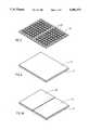
- FIG. 2is a perspective view of a reservoir array
- FIG. 3is a perspective exploded view of a reservoir array and a partially electrically conducting layer made of a single integral layer;
- FIG. 3Ais a perspective exploded view of a reservoir array and a partially electrically conducting layer made of two adjoining portions;
- FIG. 4is a perspective view of the reservoir array and partially electrically conducting layer of FIG. 3 as they appear when joined together;
- FIG. 4Ais a perspective view of the reservoir array and partially electrically conducting layer of FIG. 3 as they appear when joined together, where the partially electrically conducting layer is made of two adjoining portions;
- FIG. 5is a perspective exploded view of a reservoir array joined with a partially electrically conducting layer and a pair of electrodes;
- FIG. 5Ais a perspective exploded view of a reservoir array joined with a partially electrically conducting layer and a pair of electrodes, where the partially electrically conducting layer is made of two adjoining portions;
- FIG. 6is a perspective view of the reservoir array, partially electrically conducting layer and electrodes of FIG. 5 as they appear when joined together;
- FIG. 6Ais a perspective view of the reservoir array, partially electrically conducting layer and electrodes of FIG. 5 as they appear when joined together, where the partially electrically conducting layer is made of two adjoining portions;
- FIG. 7is a perspective view of the reservoir array, a two-portion partially electrically conducting layer as in FIG. 6A wherein the electrodes cover the entire upper surface of the partially electrically conducting layer;
- FIG. 8is a perspective view of the reservoir array, a two-portion partially electrically conducting layer, a pair of electrodes and an energy source in the form of a flat layer;
- FIG. 9is a side cross sectional view of an embodiment of an applicator according to the present invention having a removable seal
- FIG. 10is a view of the applicator of FIG. 9 following the removal of the removable seal
- FIG. 11Ashows a conventional circular applicator
- FIG. 11Bshows a circular applicator according to the present invention
- FIG. 12Ashows how the current lines of an applicator as in FIG. 11A concentrate at the site of an inhomogeneity
- FIG. 12Bshows that current lines of an applicator as in FIG. 11B remain largely unchanged
- FIG. 13Ashows how the current lines of an applicator as in FIG. 11A concentrate at the site of a short circuit
- FIG. 13Bshows that current lines of an applicator as in FIG. 11B remain largely unaffected by a short circuit
- FIG. 14Ashows that the voltage drop across an applicator as in FIG. 11A is constant when the applicator is properly placed
- FIG. 14Bshows that the voltage drop across an application as in FIG. 11B is constant when the applicator is properly placed
- FIG. 15Ashows that the voltage drop across an application as in FIG. 11A is the same regardless of whether the applicator is properly or improperly placed;
- FIG. 15Bshows that the voltage drop across an application as in FIG. 11B is very different when the applicator is improperly placed than it is when the applicator is improperly placed.
- the present inventionis of an inexpensive yet rugged transcutaneous drug delivery applicator which has the ability of effectively limiting the amount of current which is able to reach specific locations on the skin.
- FIGS. 1 and 1Aillustrate, in cross-section, one embodiment of an applicator according to the present invention.
- the illustrated applicatoris made up of a number of components which will be identified next and whose structure and function will be described in more detail below.
- the applicatorincludes a reservoir array 10 at its side nearest the skin 11 onto which the device is to be applied.
- a partially electrically conducting layer 12which may be made of a single layer or which alternatively be made of two adjoining layers lying side by side, as is described below. While partially electrically conducting layer 12 will be referred to in the singular throughout the specification and in the claims, it is intended that such terminology also includes the case where the layer is made up of two or more segments which lie in substantially the same plane and which approximately adjoin each other but are preferably somewhat separated from each other.
- a pair of electrodes 14Located immediately above, and in contact with, partially electrically conducting layer 12 is a pair of electrodes 14.
- Electrodes 14lie an array of batteries 16, or other suitable power source, as described below, which are electrically connected to each other and to electrodes 14 is some suitable manner which will be described below.
- Batteries 16may be electrically insulated from electrodes 14 by an insulating layer 18 interposed between electrodes 14 and batteries 16.
- Batteries 16 and the entire assemblyis enclosed in a suitable casing or housing 20 which may also enclose an activator or microprocessor 22 for controlling the operation of the applicator and may further feature an activation button 24 and a bolus button 26, as will be described below.
- FIG. 1Each of the above-identified components will next be further described with reference to FIG. 1 and further in reference to FIGS. 2-6 which form a series of perspective construction diagrams showing the shape and location of the various key components of an applicator according to the present invention.
- FIG. 1Shown in FIG. 1 is a view of reservoir array 10 which forms the lowest components of an applicator according to the present invention, i.e., the component which comes in direct contact with skin 11 of the patient, and which contains the drug to be administered to the patient.
- Reservoir array 10may be of any suitable length, width and height and may be made of any suitable material, preferably silicon, provided that the reservoirs are electrically insulated from each other.
- reservoir array 10is made of a single electrically insulating body which is formed with an array of preferably regularly shaped volumes 30 integrally formed therein.
- volume 30may alternatively be irregular microscopic, or smaller, structures, such as the pore structure of a suitable insulating material.
- the volume 30are filled with suitable electrically conductive material, such as various electrically conductive gels. Some of volumes 30 contain, in addition, suitable amounts of one or more drugs, typically suspended or dissolved in the conductive gel. In the example of FIG. 2, it will be assumed for purposes of illustration that half of volumes 30, say, the 54 reservoirs nearest the viewer, contain drug, while the other 54 do not.
- the drugs included in some of volumes 30are either in ionized form or become ionized upon the application of an electric field.
- the charge of the ionized drugsis the same as that of volumes 30 wherein it is located, which causes the drug to be driven out of its volumes 30 and into skin 11 which immediately underlies it.
- the electrically conductive gelis typically sufficiently viscous as to remain in volumes 30 while the drug molecules make their way, under the influence of the electromotive force, through the gel and into the skin.
- the bottom portion of the reservoir array 10may be covered with a disposable sealing layer (not shown) which is removed just prior to the deployment of the applicator.
- the bottom-directed openings of volumes 30may be covered by a microporous or semi-permeable membrane which allows drug molecules to leave volume 30 but which prevents the escape of the conductive gel.
- partially electrically conducting layer 12overlying at least two volumes 30 of reservoir array 10, and, preferably, laminated, deposited or painted onto it, or co-injected with it, is partially electrically conducting layer 12.
- a single partially electrically conducting layer 12overlies all volumes 30 of reservoir 10.
- partially electrically conducting layer 12is made up of two segments, 12a and 12b, somewhat separated from each other, each of which overlies a portion, preferably substantially one half, of volumes 30 and which preferably substantially correspond in extent and coverage with the two electrodes described below. Splitting partially electrically conducting layer 12 into two segments aids in further electrically separating the zones of influence of the two electrodes.
- Partially electrically conducting layer 12, or 12a and 12bmay be made of any suitable material, such as electrically conducting polymers such as suitable vinyls or epoxies or carbon loaded or surface metallized plastics.
- electrically conducting polymerssuch as suitable vinyls or epoxies or carbon loaded or surface metallized plastics.
- partially electrically conducting layer 12, or 12a and 12bis made up of a semiconducting material, such as silicon containing carbon (graphite) particles.
- partially electrically conducting layer 12presents a certain suitably selected resistance to current flow in the direction perpendicular to its large surfaces but offers virtually infinite resistance to current flow in the direction parallel to its large surfaces, thereby causing current to flow directly downward through the layer and virtually preventing any current from flowing sideways.
- Partially electrically conducting layer 12thus in effect constitutes an array of resistors of suitable resistive value in the vertical direction but without the large expense and operational difficulties of dedicated discrete resistors and electrodes for each of the reservoirs.
- electrodes 14which may be made of any suitable material including, but not limited to, aluminum or other metallic foil or conductive rubber or resin film. Shown in FIGS. 5 and 6 and in FIGS. 5A and 6A is a preferred embodiment wherein a single pair of electrodes 14 is used, each electrode covering approximately half of the active surface of the applicator, corresponding to approximately half of the reservoirs. In the configuration of FIGS. 5A and 6A the two portions of partially electrically conductive layer, 12a and 12b, substantially correspond in their coverage to that of electrodes 14. It will, however, be readily appreciated that it is possible to use an array of pairs of electrodes, for example with each member of each pair of electrodes overlying one or a small number of volumes 30.
- Electrodes 14extend to fully cover the entire surface of partially electrically conducting layer 12, or 12a and 12b.
- Such a configurationmakes it easier to laminated or co-inject electrodes 14, preferably made of a suitable plastic impregnated with conductive components, such as graphite, to form a monolithic structure.
- a devicefurther includes a suitable electrical power source, preferably batteries 16 (FIGS. 1 and 1A), which is electrically connected in some suitable fashion (not shown) to electrodes 14.
- the power sourceis an array of miniaturized batteries, for example, those used in electrically driven watches, which are connected in series. It will be appreciated that a variety of power sources, including any of a large number of possible batteries configured in any suitable manner, may be employed.
- the power sourcemay be in the form of a energy providing layer 116 located directly above electrodes 14, as shown in FIG. 8.
- Energy providing layer 116may be made of a suitable plastic material and may be laminated onto, or be co-injected with, the layer or layers which it overlies.
- an applicator according to the present inventioncomes in pre-packaged, disposable units which are ready for application to the skin.
- each applicatorcomes packaged in a housing which is made up of two portions--an upper casing 120 which is preferably permanently attached to the applicator, or may be an integral part thereof, and a removable seal 122 which seals reservoir array 10 prior to deployment of the applicator.
- upper casing 120 and removable seal 122are connected to each other around their adjoining peripheries. Any suitable means can be used to effect this connection.
- removable seal 122is stripped off and discarded exposing the lower portions of reservoir array 10 (FIG. 10) and the periphery of upper casing 120.
- the newly exposed surfaces of upper casing 120feature a suitable adhesive material which will aid in retaining the applicator on the skin after the applicator has been pressed onto the skin.
- the lowermost surfaces of solid elements making up reservoir array 10e.g., the insulator walls, also feature a suitable adhesive. The presence of adhesive at these points makes for a more uniform contact between reservoir array 10 and the skin of the user.
- the electrical connection between the power source and electrodes 14may be effected by various means, including, but not limited to, the use of electric lead wires, metal foil, and the like.
- casing or housing 20may, in preferred embodiments according to the present invention, also include an activator or similar means for turning the power supply on and off.
- casing or housing 20may feature an activation button 24.
- Casing or housing 20may further include a bolus button 26, which will allow for the temporary increase the rate of drug injection. Such increases are often desirable in the administration of pain killers where the patient desires to temporarily increase the dosage to meet unusually strong pains. It is to be noted that because an applicator according to the present invention is designed to limit the local current density applied to the skin, a bolus delivery mechanism may be readily use without fear of irritation or burns.
- an applicator according to the present inventionfurther includes a microprocessor 22 for controlling the rate of administration of the drug.
- Microprocessor 22may be used to administer the drug based on one or more of several pre-determined program which may be fixed by the drug manufacturer, the physician and/or the patient to optimize the drug delivery by maximizing the effectiveness of the drug and minimizing any deleterious effects.
- a devicecould be configured with one of the sets of volumes located centrally and surrounded by a second set of volumes which forms an annulus around the first set. That is, the applicator could, for example, be circular with one electrode (say, the anode) and its associated medicine-containing volumes located at or near the center of the circle while the second electrode (say, the cathode) and its associated medicine-containing volumes form a ring around the first electrode.
- the applicatorcould, for example, be circular with one electrode (say, the anode) and its associated medicine-containing volumes located at or near the center of the circle while the second electrode (say, the cathode) and its associated medicine-containing volumes form a ring around the first electrode.
- FIGS. 11-15Shown in FIGS. 11-15 are cross-sectional views of such circular applicators as they would appear when applied to the skin of the patient (not shown), with FIGS. 11A, 12A, 13A, 14A and 15A showing prior art applicators while FIGS. 11B, 12B, 13B, 14B and 15B show corresponding applicators according to the present invention.
- a conventional circular applicator(FIG. 11A) includes a central electrode 300 and an annular electrode 302, completely overlying, respectively, a central common reservoir 304 and an annular common reservoir 306. Also shown in FIG. 11A are the locations within the skin of the patient (not shown) of three representative electrical current lines 310, 312, and 314. It will be appreciated that current line 310, which is closest to the applicator and which is the shortest of the current lines shown, will pass more current that will current line 312 which is longer. Current line 312, in turn, will pass more current than current line 314 which is longer yet. The relative amount of current passed is indicated schematically by the thickness of the current lines.
- FIG. 11BShown in FIG. 11B is a circular applicator according to the present invention.
- a central electrode 400 and an annular electrode 402partly overly, respectively, a central partially electrically conducting layer 420 and an annular partially electrically conducting layer 422, which may be made of materials similar to those described in the context of the basic embodiments of FIGS. 1-10.
- Central partially electrically conducting layer 420 and annular partially electrically conducting layer 422,in turn, overly, preferably completely, a central partitioned reservoir 404 and an annular partitioned reservoir 406.
- electrodes 402 and 404 and of reservoirs 404 and 406 and their relative placement, as well as the properties and dimensions of partially conducting layers 420 and 422are selected to reduce the disparity in the total resistance of the various current paths so that, substantially all the paths of current between central electrode 400 and annular electrode 402 tend to be of substantially equal total overall resistance and therefore carry substantially equal currents, as indicated by current lines 410, 412, and 414, which are indicated visually with lines of the same thickness.
- current following current line 414goes from annular electrode 402, directly through the thickness of annular partially electrically conducting layer 422, through one of the volumes of annular reservoir array 406, through the skin via current line 414, through one of the volumes of central reservoir array 404, directly through the thickness of central partially electrical conducting layer 420, and to central electrode 400.
- current following current line 410leaves annular electrode 402 and must travel transversely across annular partially electrical conducting layer 422 from a position near its outer periphery to a position near its inner periphery while at the same time the current must go through the thickness of annular partially electrical conducting layer 422.
- the currentmust then go through one of the volumes of annular reservoir array 406, through the skin via current line 410, through one of the volumes of central reservoir array 404.
- the currentmust then traverse the thickness of central partially electrical conducting layer 420 while also traveling across it from a point near its outer periphery to a point near its center where central electrode 400 is located.
- FIGS. 12-15Schematically depicted in FIG. 12A is the occurrence of a hot spot using a conventional applicator.
- an applicator according to the present inventionas shown in FIG. 12B, creates a uniform zone of low current density.
- an inhomogeneityis encountered only a small portion of the current is able to concentrate.
- FIGS. 14B and 15Ban applicator according to the present invention
- FIGS. 14A and 15Acan be used to give accurate indications of its improper placement on the skin of the patient.
- FIGS. 14A and 14BShown in FIGS. 14A and 14B is the case where both applicators are properly placed. As described above, the current field produced by an applicator according to the present invention will be much more uniform than that produced by a conventional applicator. However, when the overall potential is measured across either well-placed applicator, the voltage drop will be the same.
- the scheme represented in the embodiment of FIGS. 11B to 15Bcan be implemented in geometries other than those involving a central electrode and a surrounding annular electrode.
- the same schemecan be implemented in the context of the embodiments of FIGS. 1-10 by sizing and dimensioning the electrodes so as to cover only a small fraction of the surface of the partially conduction layer or layers and by placing each of the electrodes near the edge of the applicator which is farthest removed from the other electrode.
- a scheme such as that described abovemay be implemented by using electrodes such as those in the embodiments of FIGS. 1-10 which overly all or most of the partially conducting layer or layers, but where other means are used to ensure that different portions of the current see different resistance while traversing the partially conducting layer or layers, for example, by using partially conducting layer or layers having varying thicknesses, and thus resistivities, for different current lines.
Landscapes
- Health & Medical Sciences (AREA)
- Engineering & Computer Science (AREA)
- Bioinformatics & Cheminformatics (AREA)
- General Health & Medical Sciences (AREA)
- Biomedical Technology (AREA)
- Nuclear Medicine, Radiotherapy & Molecular Imaging (AREA)
- Radiology & Medical Imaging (AREA)
- Life Sciences & Earth Sciences (AREA)
- Animal Behavior & Ethology (AREA)
- Public Health (AREA)
- Veterinary Medicine (AREA)
- Pharmacology & Pharmacy (AREA)
- Electrotherapy Devices (AREA)
- Medicinal Preparation (AREA)
Abstract
Description
Claims (17)
Priority Applications (9)
| Application Number | Priority Date | Filing Date | Title |
|---|---|---|---|
| US08/077,146US5380272A (en) | 1993-01-28 | 1993-06-16 | Transcutaneous drug delivery applicator |
| AU61240/94AAU6124094A (en) | 1993-01-28 | 1994-01-14 | Transcutaneous drug delivery applicator |
| CA002154903ACA2154903A1 (en) | 1993-01-28 | 1994-01-14 | Transcutaneous drug delivery applicator |
| ES94907823TES2160120T3 (en) | 1993-01-28 | 1994-01-14 | APPLICATOR FOR THE TRANSCUTANEOUS SUPPLY OF PHARMACOS. |
| JP6517137AJP2807800B2 (en) | 1993-01-28 | 1994-01-14 | Transdermal drug delivery applicator |
| PCT/US1994/000553WO1994016765A1 (en) | 1993-01-28 | 1994-01-14 | Transcutaneous drug delivery applicator |
| AT94907823TATE202291T1 (en) | 1993-01-28 | 1994-01-14 | APPLICATOR FOR TRANSCUTANEOUS ADMINISTRATION OF A MEDICATION |
| DE69427526TDE69427526T2 (en) | 1993-01-28 | 1994-01-14 | APPLICATOR FOR TRANSCUTANEOUS ADMINISTRATION OF A MEDICINE |
| EP94907823AEP0681497B1 (en) | 1993-01-28 | 1994-01-14 | Transcutaneous drug delivery applicator |
Applications Claiming Priority (3)
| Application Number | Priority Date | Filing Date | Title |
|---|---|---|---|
| US1017893A | 1993-01-28 | 1993-01-28 | |
| US3836293A | 1993-03-29 | 1993-03-29 | |
| US08/077,146US5380272A (en) | 1993-01-28 | 1993-06-16 | Transcutaneous drug delivery applicator |
Related Parent Applications (1)
| Application Number | Title | Priority Date | Filing Date |
|---|---|---|---|
| US3836293AContinuation-In-Part | 1993-01-28 | 1993-03-29 |
Publications (1)
| Publication Number | Publication Date |
|---|---|
| US5380272Atrue US5380272A (en) | 1995-01-10 |
Family
ID=27359168
Family Applications (1)
| Application Number | Title | Priority Date | Filing Date |
|---|---|---|---|
| US08/077,146Expired - LifetimeUS5380272A (en) | 1993-01-28 | 1993-06-16 | Transcutaneous drug delivery applicator |
Country Status (9)
| Country | Link |
|---|---|
| US (1) | US5380272A (en) |
| EP (1) | EP0681497B1 (en) |
| JP (1) | JP2807800B2 (en) |
| AT (1) | ATE202291T1 (en) |
| AU (1) | AU6124094A (en) |
| CA (1) | CA2154903A1 (en) |
| DE (1) | DE69427526T2 (en) |
| ES (1) | ES2160120T3 (en) |
| WO (1) | WO1994016765A1 (en) |
Cited By (118)
| Publication number | Priority date | Publication date | Assignee | Title |
|---|---|---|---|---|
| US5695459A (en)* | 1993-06-08 | 1997-12-09 | Hisamitsu Pharmaceutical Co., Inc. | Iontophoresis system |
| US5857993A (en)* | 1996-07-12 | 1999-01-12 | Empi, Inc. | Process of making an iontophoresis electrode |
| US5871461A (en)* | 1996-07-12 | 1999-02-16 | Empi, Inc. | Method of making an iontophoresis electrode |
| US5941843A (en)* | 1996-07-12 | 1999-08-24 | Empi, Inc. | Iontophoresis electrode |
| WO2000027473A1 (en)* | 1998-11-09 | 2000-05-18 | Elecsys Ltd. | Transdermal drug delivery and analyte extraction |
| US6192270B1 (en)* | 1998-08-14 | 2001-02-20 | Genetronics, Inc. | Apparatus and method for the delivery of drugs and genes into tissue |
| WO2000074767A3 (en)* | 1999-06-08 | 2001-07-05 | Altea Tech Inc | Apparatus for microporation of biological membranes using thin film tissue interface devices, and method therefor |
| US6327496B1 (en) | 1999-07-12 | 2001-12-04 | Empi Corp. | Iontophoresis electrode |
| US6336049B1 (en)* | 1998-07-08 | 2002-01-01 | Nitto Denko Corporation | Electrode structure for reducing irritation to the skin |
| US6352506B1 (en) | 1998-07-14 | 2002-03-05 | Altea Technologies | Controlled removal of biological membrane by pyrotechnic charge for transmembrane transport |
| US20020072784A1 (en)* | 2000-10-10 | 2002-06-13 | Sheppard Norman F. | Microchip reservoir devices using wireless transmission of power and data |
| US6527716B1 (en) | 1997-12-30 | 2003-03-04 | Altea Technologies, Inc. | Microporation of tissue for delivery of bioactive agents |
| US20030078499A1 (en)* | 1999-08-12 | 2003-04-24 | Eppstein Jonathan A. | Microporation of tissue for delivery of bioactive agents |
| US6597946B2 (en) | 1998-11-09 | 2003-07-22 | Transpharma Ltd. | Electronic card for transdermal drug delivery and analyte extraction |
| US6611706B2 (en) | 1998-11-09 | 2003-08-26 | Transpharma Ltd. | Monopolar and bipolar current application for transdermal drug delivery and analyte extraction |
| US20030181846A1 (en)* | 2001-12-19 | 2003-09-25 | Young Wendy A. | Reservoir housing having a conductive region integrally formed therein |
| US20030187320A1 (en)* | 2002-03-29 | 2003-10-02 | Toby Freyman | Magnetically enhanced injection catheter |
| US20030225362A1 (en)* | 2000-06-01 | 2003-12-04 | Currie John F. | Systems and methods for monitoring health and delivering drugs transdermally |
| US20030225360A1 (en)* | 2002-03-11 | 2003-12-04 | Jonathan Eppstein | Transdermal drug delivery patch system, method of making same and method of using same |
| US6708060B1 (en) | 1998-11-09 | 2004-03-16 | Transpharma Ltd. | Handheld apparatus and method for transdermal drug delivery and analyte extraction |
| US20040121486A1 (en)* | 2002-08-16 | 2004-06-24 | Uhland Scott A. | Controlled release device and method using electrothermal ablation |
| US20040219192A1 (en)* | 2001-01-23 | 2004-11-04 | Michael Horstmann | Devices and methods for heat-pulse assisted thermal applications of active subtances |
| US20040267237A1 (en)* | 2003-06-30 | 2004-12-30 | Ying Sun | Methods of treating acne and rosacea with electrochemically generated zinc ions |
| US20040265395A1 (en)* | 2003-06-30 | 2004-12-30 | Ying Sun | Device for delivery of reducing agents to barrier membranes |
| US20040267231A1 (en)* | 2003-06-30 | 2004-12-30 | Ying Sun | Device for delivery of oxidizing agents to barrier membranes |
| US20040267232A1 (en)* | 2003-06-30 | 2004-12-30 | Ying Sun | Device for delivery of active agents to barrier membranes |
| US20040267236A1 (en)* | 2003-06-30 | 2004-12-30 | Ying Sun | Device containing a light emitting diode for treatment of barrier membranes |
| US20050004509A1 (en)* | 2003-06-30 | 2005-01-06 | Ying Sun | Methods of administering an active agent to a human barrier membrane with galvanic generated electricity |
| US20050004508A1 (en)* | 2003-06-30 | 2005-01-06 | Ying Sun | Methods of reducing the appearance of pigmentation with galvanic generated electricity |
| US20050010161A1 (en)* | 2003-06-30 | 2005-01-13 | Ying Sun | Methods of treating acne and rosacea with galvanic generated electricity |
| US20050010192A1 (en)* | 2003-06-30 | 2005-01-13 | Ying Sun | Methods of treating pores on the skin with electricity |
| US20050015042A1 (en)* | 2003-06-30 | 2005-01-20 | Ying Sun | Methods of exfoliating the skin with electricity |
| US20050119605A1 (en)* | 2002-04-19 | 2005-06-02 | Transpharma Medical Ltd. | Handheld transdermal drug delivery and analyte extraction |
| US20050124979A1 (en)* | 2000-03-02 | 2005-06-09 | Santini John T.Jr. | Device for release of chemical molecules using pressure-generated rupture of reservoirs |
| US20050143715A1 (en)* | 2001-05-31 | 2005-06-30 | Cima Michael J. | Device for controlled reservoir opening with reinforced reservoir caps |
| US20060057737A1 (en)* | 2004-09-01 | 2006-03-16 | Santini John T Jr | Multi-cap reservoir devices for controlled release or exposure of reservoir contents |
| US20060095001A1 (en)* | 2004-10-29 | 2006-05-04 | Transcutaneous Technologies Inc. | Electrode and iontophoresis device |
| US20060135906A1 (en)* | 2004-11-16 | 2006-06-22 | Akihiko Matsumura | Iontophoretic device and method for administering immune response-enhancing agents and compositions |
| US7070590B1 (en)* | 1996-07-02 | 2006-07-04 | Massachusetts Institute Of Technology | Microchip drug delivery devices |
| US20060235351A1 (en)* | 2005-04-15 | 2006-10-19 | Transcutaneous Technologies Inc. | External preparation, method of applying external preparation, iontophoresis device, and percutaneous patch |
| US20070021711A1 (en)* | 2005-06-23 | 2007-01-25 | Transcutaneous Technologies, Inc. | Iontophoresis device controlling administration amount and administration period of plurality of drugs |
| US20070048362A1 (en)* | 2005-08-29 | 2007-03-01 | Transcutaneous Technologies Inc. | General purpose electrolyte solution composition for iontophoresis |
| US20070060859A1 (en)* | 2005-08-08 | 2007-03-15 | Transcutaneous Technologies Inc. | Iontophoresis device |
| US20070066932A1 (en)* | 2005-09-15 | 2007-03-22 | Transcutaneous Technologies Inc. | Iontophoresis device |
| US20070066930A1 (en)* | 2005-06-20 | 2007-03-22 | Transcutaneous Technologies, Inc. | Iontophoresis device and method of producing the same |
| US20070078376A1 (en)* | 2005-09-30 | 2007-04-05 | Smith Gregory A | Functionalized microneedles transdermal drug delivery systems, devices, and methods |
| US20070074590A1 (en)* | 2005-09-30 | 2007-04-05 | Transcutaneous Technologies Inc. | Method and system to detect malfunctions in an iontophoresis device that delivers active agents to biological interfaces |
| US20070078374A1 (en)* | 2005-09-30 | 2007-04-05 | Transcutaneous Technologies Inc. | Iontophoretic delivery of vesicle-encapsulated active agents |
| US20070083186A1 (en)* | 2005-09-30 | 2007-04-12 | Darrick Carter | Transdermal drug delivery systems, devices, and methods employing novel pharmaceutical vehicles |
| US20070083185A1 (en)* | 2005-09-30 | 2007-04-12 | Darrick Carter | Iontophoretic device and method of delivery of active agents to biological interface |
| US20070088332A1 (en)* | 2005-08-22 | 2007-04-19 | Transcutaneous Technologies Inc. | Iontophoresis device |
| US20070087608A1 (en)* | 2005-10-18 | 2007-04-19 | Der-Yang Tien | Delivery Device and Method |
| US20070093787A1 (en)* | 2005-09-30 | 2007-04-26 | Transcutaneous Technologies Inc. | Iontophoresis device to deliver multiple active agents to biological interfaces |
| US20070112294A1 (en)* | 2005-09-14 | 2007-05-17 | Transcutaneous Technologies Inc. | Iontophoresis device |
| US20070110810A1 (en)* | 2005-09-30 | 2007-05-17 | Transcutaneous Technologies Inc. | Transdermal drug delivery systems, devices, and methods employing hydrogels |
| US20070135754A1 (en)* | 2005-09-30 | 2007-06-14 | Hidero Akiyama | Electrode assembly for iontophoresis for administering active agent enclosed in nanoparticle and iontophoresis device using the same |
| US20070197955A1 (en)* | 2005-10-12 | 2007-08-23 | Transcutaneous Technologies Inc. | Mucous membrane adhesion-type iontophoresis device |
| US20070275035A1 (en)* | 2006-05-24 | 2007-11-29 | Microchips, Inc. | Minimally Invasive Medical Implant Devices for Controlled Drug Delivery |
| US20080004564A1 (en)* | 2006-03-30 | 2008-01-03 | Transcutaneous Technologies Inc. | Controlled release membrane and methods of use |
| US20080027369A1 (en)* | 2005-12-30 | 2008-01-31 | Transcutaneous Technologies Inc. | Iontophoretic systems, devices, and methods of delivery of active agents to biological interface |
| US20080033338A1 (en)* | 2005-12-28 | 2008-02-07 | Smith Gregory A | Electroosmotic pump apparatus and method to deliver active agents to biological interfaces |
| US20080033398A1 (en)* | 2005-12-29 | 2008-02-07 | Transcutaneous Technologies Inc. | Device and method for enhancing immune response by electrical stimulation |
| US20080071252A1 (en)* | 2001-01-09 | 2008-03-20 | Microchips, Inc. | Method of actuating implanted medical device |
| US20080076975A1 (en)* | 2005-01-25 | 2008-03-27 | Microchips, Inc. | Method and implantable device with reservoir array for pre-clinical in vivo testing |
| US20080076345A1 (en)* | 2002-02-09 | 2008-03-27 | Aloys Wobben | Fire protection |
| US20080114211A1 (en)* | 2006-09-29 | 2008-05-15 | Edward Karst | System and method for assuring validity of monitoring parameter in combination with a therapeutic device |
| US20080114282A1 (en)* | 2006-09-05 | 2008-05-15 | Transcu Ltd. | Transdermal drug delivery systems, devices, and methods using inductive power supplies |
| US20080188791A1 (en)* | 2007-02-02 | 2008-08-07 | Difiore Attilio E | Active iontophoresis delivery system |
| US20080262581A1 (en)* | 2007-04-17 | 2008-10-23 | Transport Pharmaceuticals, Inc. | Current density detection and control system and method for an electrokinetic delivery of medicaments |
| US20080274166A1 (en)* | 2005-06-10 | 2008-11-06 | Transpharma Medical Ltd. | Patch for Transdermal Drug Delivery |
| US20080286349A1 (en)* | 2007-05-18 | 2008-11-20 | Youhei Nomoto | Systems, devices, and methods for passive transdermal delivery of active agents to a biological interface |
| US20080305154A1 (en)* | 2007-06-08 | 2008-12-11 | Activatek, Inc. | Transdermal medicament patch and active electrode for same |
| US7473248B2 (en) | 1999-08-18 | 2009-01-06 | Microchips, Inc. | Thermally-activated reservoir devices |
| US20090187134A1 (en)* | 2005-09-30 | 2009-07-23 | Hidero Akiyama | Iontophoresis Device Controlling Amounts of a Sleep-Inducing Agent and a Stimulant to be Administered and Time at Which the Drugs are Administered |
| US7574256B2 (en) | 2005-09-30 | 2009-08-11 | Tti Ellebeau, Inc. | Iontophoretic device and method of delivery of active agents to biological interface |
| US20090214625A1 (en)* | 2005-07-15 | 2009-08-27 | Mizuo Nakayama | Drug delivery patch |
| US20090216177A1 (en)* | 2005-09-16 | 2009-08-27 | Tti Ellebeau,Inc | Catheter-type iontophoresis device |
| US7599737B2 (en) | 2002-10-04 | 2009-10-06 | Microchips, Inc. | Medical device for neural stimulation and controlled drug delivery |
| US20090254018A1 (en)* | 2005-08-24 | 2009-10-08 | Mizuo Nakayama | Electrode assembly for freezing-type iontophoresis device |
| US20090281404A1 (en)* | 2004-12-09 | 2009-11-12 | John Frederick Currie | Appartus and Method for Continuous Real-Time Trace Biomolecular Sampling, Analysis, and Delivery |
| US20090299264A1 (en)* | 2005-09-28 | 2009-12-03 | Tti Ellebeau, Inc. | Electrode Assembly for Dry Type Iontophoresis |
| US20090299265A1 (en)* | 2005-09-30 | 2009-12-03 | Tti Ellebeau, Inc. | Electrode Assembly for Iontophoresis Having Shape-Memory Separator and Iontophoresis Device Using the Same |
| US20090308742A1 (en)* | 2005-12-09 | 2009-12-17 | Makarand Paranjape | Flexible Apparatus and Method for Monitoring and Delivery |
| US20100030128A1 (en)* | 2005-09-06 | 2010-02-04 | Kazuma Mitsuguchi | Iontophoresis device |
| US20100057147A1 (en)* | 2008-08-27 | 2010-03-04 | Ali Fassih | Treatment of hyperhydrosis |
| US20100069877A1 (en)* | 2008-09-10 | 2010-03-18 | Smith Gregory A | Apparatus and method to dispense hpc-based viscous liquids into porous substrates, e.g., continuous web-based process |
| US20100082088A1 (en)* | 2008-08-27 | 2010-04-01 | Ali Fassih | Treatment of sweating and hyperhydrosis |
| US20100209515A1 (en)* | 2007-09-28 | 2010-08-19 | Jeannette Chantalat | Electricity-generating particulates and the use thereof |
| US20100229636A1 (en)* | 2007-10-17 | 2010-09-16 | Galit Levin | Dissolution rate verification |
| US20100293807A1 (en)* | 2007-10-29 | 2010-11-25 | Transpharma Medical, Ltd. | Vertical patch drying |
| US20100312168A1 (en)* | 2009-06-09 | 2010-12-09 | Yoshimasa Yoshida | Long life high capacity electrode, device, and method of manufacture |
| US20110118655A1 (en)* | 2009-11-13 | 2011-05-19 | Ali Fassih | Galvanic skin treatment device |
| US20110195100A1 (en)* | 2010-02-05 | 2011-08-11 | Elizabeth Bruning | Lip compositions comprising galvanic particulates |
| US20110212042A1 (en)* | 2010-03-01 | 2011-09-01 | Prithwiraj Maitra | Skin care composition having desirable bulk color |
| US8016811B2 (en) | 2003-10-24 | 2011-09-13 | Altea Therapeutics Corporation | Method for transdermal delivery of permeant substances |
| US20110236491A1 (en)* | 2010-03-25 | 2011-09-29 | Jeannette Chantalat | Topical anti-inflammatory composition |
| US8062783B2 (en) | 2006-12-01 | 2011-11-22 | Tti Ellebeau, Inc. | Systems, devices, and methods for powering and/or controlling devices, for instance transdermal delivery devices |
| AU2011205219B2 (en)* | 2000-06-01 | 2011-11-24 | Georgetown University | Systems and methods for monitoring health and delivering drugs transdermally |
| US8095197B2 (en) | 2003-11-03 | 2012-01-10 | Microchips, Inc. | Medical device for sensing glucose |
| US8116860B2 (en) | 2002-03-11 | 2012-02-14 | Altea Therapeutics Corporation | Transdermal porator and patch system and method for using same |
| US20120253224A1 (en)* | 2011-03-30 | 2012-10-04 | SensiVida Medical Technologies, Inc. | Skin test image analysis apparatuses and methods thereof |
| US8295922B2 (en) | 2005-08-08 | 2012-10-23 | Tti Ellebeau, Inc. | Iontophoresis device |
| AU2012201079B2 (en)* | 2000-06-01 | 2013-03-28 | Georgetown University | Systems and methods for monitoring health and delivering drugs transdermally |
| US8862223B2 (en) | 2008-01-18 | 2014-10-14 | Activatek, Inc. | Active transdermal medicament patch and circuit board for same |
| CN104147694A (en)* | 2003-06-30 | 2014-11-19 | 强生消费者公司 | Device for treating human or animal barrier film |
| US20140378889A1 (en)* | 2012-06-18 | 2014-12-25 | Michael Tavger | Method and system for delivering solution into the pores of recipient human skin |
| AU2014200664B2 (en)* | 2000-06-01 | 2015-05-14 | Georgetown University | Systems and methods for monitoring health and delivering drugs transdermally |
| US9044397B2 (en) | 2009-03-27 | 2015-06-02 | Ethicon, Inc. | Medical devices with galvanic particulates |
| US9451913B2 (en) | 2010-12-10 | 2016-09-27 | Touchtek Labs, Llc | Transdermal sampling and analysis device |
| US9504826B2 (en) | 2009-02-18 | 2016-11-29 | Syneron Medical Ltd | Skin treatment apparatus for personal use and method for using same |
| US9877673B2 (en) | 2010-12-10 | 2018-01-30 | Clinitech, Llc | Transdermal sampling and analysis device |
| US9918665B2 (en) | 2002-03-11 | 2018-03-20 | Nitto Denko Corporation | Transdermal porator and patch system and method for using same |
| US9968284B2 (en) | 2011-12-02 | 2018-05-15 | Clinitech, Llc | Anti-interferent barrier layers for non-invasive transdermal sampling and analysis device |
| US10004434B1 (en) | 2013-03-15 | 2018-06-26 | Georgetown University | Microfluidic systems for electrochemical transdermal analyte sensing using a capillary-located electrode |
| US11219390B2 (en) | 2015-08-03 | 2022-01-11 | Georgetown University | Apparatus and method for delivery of antimicrobial during a transdermal sampling and delivery process |
| US11375931B2 (en) | 2019-08-08 | 2022-07-05 | Cambridge Medical Technologies LLC | Non-invasive transdermal sampling and analysis device incorporating an electrochemical bioassay |
| US11633129B2 (en) | 2019-04-05 | 2023-04-25 | Cambridge Medical Technologies LLC | Non-invasive transdermal sampling and analysis device incorporating redox cofactors |
| US12201422B2 (en) | 2013-03-15 | 2025-01-21 | Cambridge Medical Technologies LLC | Methods of manufacture to optimize performance of transdermal sampling and analysis device |
Families Citing this family (5)
| Publication number | Priority date | Publication date | Assignee | Title |
|---|---|---|---|---|
| JPH10151208A (en)* | 1996-11-21 | 1998-06-09 | Poritoronikusu:Kk | Percutaneous administration element |
| US6757560B1 (en) | 1999-04-09 | 2004-06-29 | Novosis Pharma Ag | Transdermal delivery system (TDS) with electrode network |
| DE19816143A1 (en)* | 1998-04-09 | 1999-10-21 | Fischer Wilfried | Transdermal application system (TDS) with electrode grid |
| DE102010024558B4 (en) | 2010-06-22 | 2016-04-21 | Amw Gmbh | Transdermal therapeutic system with electrodes |
| CN111888641B (en)* | 2019-05-06 | 2023-09-22 | 上海肤泰科技有限公司 | Iontophoresis drug delivery device |
Citations (5)
| Publication number | Priority date | Publication date | Assignee | Title |
|---|---|---|---|---|
| US4708716A (en)* | 1983-08-18 | 1987-11-24 | Drug Delivery Systems Inc. | Transdermal drug applicator |
| US4731926A (en)* | 1985-02-19 | 1988-03-22 | Drug Delivery Systems Inc. | Method of manufacturing disposable and/or replenishable transdermal drug applicators |
| US4865582A (en)* | 1987-06-05 | 1989-09-12 | Drug Delivery Systems Inc. | Disposable transdermal drug applicators |
| US4883457A (en)* | 1983-08-18 | 1989-11-28 | Drug Delivery Systems Inc. | Disposable and/or replenishable transdermal drug applicators and methods of manufacturing same |
| US5002527A (en)* | 1988-04-14 | 1991-03-26 | Inventor's Funding Corp. Ltd. | Transdermal drug delivery applicators |
- 1993
- 1993-06-16USUS08/077,146patent/US5380272A/ennot_activeExpired - Lifetime
- 1994
- 1994-01-14JPJP6517137Apatent/JP2807800B2/ennot_activeExpired - Fee Related
- 1994-01-14CACA002154903Apatent/CA2154903A1/ennot_activeAbandoned
- 1994-01-14AUAU61240/94Apatent/AU6124094A/ennot_activeAbandoned
- 1994-01-14WOPCT/US1994/000553patent/WO1994016765A1/enactiveIP Right Grant
- 1994-01-14DEDE69427526Tpatent/DE69427526T2/ennot_activeExpired - Fee Related
- 1994-01-14ESES94907823Tpatent/ES2160120T3/ennot_activeExpired - Lifetime
- 1994-01-14EPEP94907823Apatent/EP0681497B1/ennot_activeExpired - Lifetime
- 1994-01-14ATAT94907823Tpatent/ATE202291T1/enactive
Patent Citations (6)
| Publication number | Priority date | Publication date | Assignee | Title |
|---|---|---|---|---|
| US4708716A (en)* | 1983-08-18 | 1987-11-24 | Drug Delivery Systems Inc. | Transdermal drug applicator |
| US4883457A (en)* | 1983-08-18 | 1989-11-28 | Drug Delivery Systems Inc. | Disposable and/or replenishable transdermal drug applicators and methods of manufacturing same |
| US4731926A (en)* | 1985-02-19 | 1988-03-22 | Drug Delivery Systems Inc. | Method of manufacturing disposable and/or replenishable transdermal drug applicators |
| US4865582A (en)* | 1987-06-05 | 1989-09-12 | Drug Delivery Systems Inc. | Disposable transdermal drug applicators |
| US5002527A (en)* | 1988-04-14 | 1991-03-26 | Inventor's Funding Corp. Ltd. | Transdermal drug delivery applicators |
| US5053001A (en)* | 1988-04-14 | 1991-10-01 | Inventor's Funding Company Ltd. | Transdermal drug delivery device with multiple reservoirs |
Cited By (234)
| Publication number | Priority date | Publication date | Assignee | Title |
|---|---|---|---|---|
| US5695459A (en)* | 1993-06-08 | 1997-12-09 | Hisamitsu Pharmaceutical Co., Inc. | Iontophoresis system |
| US7918842B2 (en) | 1996-07-02 | 2011-04-05 | Massachusetts Institute Of Technology | Medical device with controlled reservoir opening |
| US7070590B1 (en)* | 1996-07-02 | 2006-07-04 | Massachusetts Institute Of Technology | Microchip drug delivery devices |
| US7892221B2 (en) | 1996-07-02 | 2011-02-22 | Massachusetts Institute Of Technology | Method of controlled drug delivery from implant device |
| US7901397B2 (en) | 1996-07-02 | 2011-03-08 | Massachusetts Institute Of Technology | Method for operating microchip reservoir device |
| US20080051766A1 (en)* | 1996-07-02 | 2008-02-28 | Massachusetts Institute Of Technology | Method for Operating Microchip Reservoir Device |
| US5857993A (en)* | 1996-07-12 | 1999-01-12 | Empi, Inc. | Process of making an iontophoresis electrode |
| US5871461A (en)* | 1996-07-12 | 1999-02-16 | Empi, Inc. | Method of making an iontophoresis electrode |
| US5941843A (en)* | 1996-07-12 | 1999-08-24 | Empi, Inc. | Iontophoresis electrode |
| US20050165393A1 (en)* | 1996-12-31 | 2005-07-28 | Eppstein Jonathan A. | Microporation of tissue for delivery of bioactive agents |
| US9579380B2 (en) | 1996-12-31 | 2017-02-28 | Ntt Denko Corporation | Microporation of tissue for delivery of bioactive agents |
| US6527716B1 (en) | 1997-12-30 | 2003-03-04 | Altea Technologies, Inc. | Microporation of tissue for delivery of bioactive agents |
| US7758561B2 (en) | 1997-12-30 | 2010-07-20 | Altea Therapeutics Corporation | Microporation of tissue for delivery of bioactive agents |
| US20040220456A1 (en)* | 1997-12-30 | 2004-11-04 | Altea Therapeutics Corporation | Microporation of tissue for delivery of bioactive agents |
| US20100217212A1 (en)* | 1997-12-30 | 2010-08-26 | Eppstein Jonathan A | Microporation of Tissue for Delivery of Bioactive Agents |
| US6336049B1 (en)* | 1998-07-08 | 2002-01-01 | Nitto Denko Corporation | Electrode structure for reducing irritation to the skin |
| US6352506B1 (en) | 1998-07-14 | 2002-03-05 | Altea Technologies | Controlled removal of biological membrane by pyrotechnic charge for transmembrane transport |
| US6730028B2 (en) | 1998-07-14 | 2004-05-04 | Altea Therapeutics Corporation | Controlled removal of biological membrane by pyrotechnic charge for transmembrane transport |
| US6748265B2 (en) | 1998-08-14 | 2004-06-08 | Genetronics, Inc. | Electrode apparatus and method for the delivery of drugs and genes into tissue |
| US6192270B1 (en)* | 1998-08-14 | 2001-02-20 | Genetronics, Inc. | Apparatus and method for the delivery of drugs and genes into tissue |
| US20040176716A1 (en)* | 1998-08-14 | 2004-09-09 | Hofmann Gunter A. | Electrode apparatus and method for the delivery of drugs and genes into tissue |
| US7395110B2 (en) | 1998-08-14 | 2008-07-01 | Genetronics, Inc. | Electrode apparatus and method for the delivery of drugs and genes into tissue |
| US6615079B1 (en) | 1998-11-09 | 2003-09-02 | Elecsys Ltd. | Transdermal drug delivery and analyte extraction |
| AU768938B2 (en)* | 1998-11-09 | 2004-01-08 | Transpharma Ltd. | Transdermal drug delivery and analyte extraction |
| WO2000027473A1 (en)* | 1998-11-09 | 2000-05-18 | Elecsys Ltd. | Transdermal drug delivery and analyte extraction |
| JP2002529159A (en)* | 1998-11-09 | 2002-09-10 | エレクシス リミティド | Transdermal drug release and analyte extraction |
| US6611706B2 (en) | 1998-11-09 | 2003-08-26 | Transpharma Ltd. | Monopolar and bipolar current application for transdermal drug delivery and analyte extraction |
| US6708060B1 (en) | 1998-11-09 | 2004-03-16 | Transpharma Ltd. | Handheld apparatus and method for transdermal drug delivery and analyte extraction |
| US6711435B2 (en) | 1998-11-09 | 2004-03-23 | Transpharma Ltd. | Transdermal drug delivery and analyte extraction |
| US6597946B2 (en) | 1998-11-09 | 2003-07-22 | Transpharma Ltd. | Electronic card for transdermal drug delivery and analyte extraction |
| US7164942B2 (en) | 1998-11-09 | 2007-01-16 | Transpharma Medical Ltd. | Handheld apparatus and method for transdermal drug delivery and analyte extraction |
| US20040230227A1 (en)* | 1998-11-09 | 2004-11-18 | Zohar Avrahami | Handheld apparatus and method for transdermal drug delivery and analyte extraction |
| US20030208152A1 (en)* | 1998-11-09 | 2003-11-06 | Zohar Avrahami | Electronic card for transdermal drug delivery and analyte extraction |
| EP2168497A3 (en)* | 1999-06-08 | 2010-12-01 | Altea Therapeutics Corporation | Apparatus for microporation of biological membranes using thin film tissue interface devices |
| US8517958B2 (en) | 1999-06-08 | 2013-08-27 | Nitto Denko Corporation | Transdermal integrated actuator device, methods of making and using same |
| WO2000074767A3 (en)* | 1999-06-08 | 2001-07-05 | Altea Tech Inc | Apparatus for microporation of biological membranes using thin film tissue interface devices, and method therefor |
| EP1645305A1 (en)* | 1999-06-08 | 2006-04-12 | Altea Therapeutics Corporation | Apparatus for microporation of biological membranes using thin film tissue interface devices, and method for manufacturing |
| US6692456B1 (en) | 1999-06-08 | 2004-02-17 | Altea Therapeutics Corporation | Apparatus for microporation of biological membranes using thin film tissue interface devices, and method therefor |
| EP2286868A3 (en)* | 1999-06-08 | 2012-05-16 | Altea Therapeutics Corporation | Apparatus for microporation of biological membranes using thin film tissue interface devices, and method for manufacturing |
| US6327496B1 (en) | 1999-07-12 | 2001-12-04 | Empi Corp. | Iontophoresis electrode |
| US20030078499A1 (en)* | 1999-08-12 | 2003-04-24 | Eppstein Jonathan A. | Microporation of tissue for delivery of bioactive agents |
| US20030092982A1 (en)* | 1999-08-12 | 2003-05-15 | Eppstein Jonathan A. | Microporation of tissue for delivery of bioactive agents |
| US7473248B2 (en) | 1999-08-18 | 2009-01-06 | Microchips, Inc. | Thermally-activated reservoir devices |
| US20050124979A1 (en)* | 2000-03-02 | 2005-06-09 | Santini John T.Jr. | Device for release of chemical molecules using pressure-generated rupture of reservoirs |
| US7648677B2 (en) | 2000-03-02 | 2010-01-19 | Microchips, Inc. | Method for operating a reservoir-based sensor device |
| US8442611B2 (en) | 2000-03-02 | 2013-05-14 | Microchips, Inc. | Medical device with reservoir-based sensors |
| US20060171888A1 (en)* | 2000-03-02 | 2006-08-03 | Microchips, Inc. | Medical Device and Method for Diagnostic Sensing |
| US20070299385A1 (en)* | 2000-03-02 | 2007-12-27 | Microchips, Inc. | Device for the controlled exposure of reservoir-based sensors |
| US20100137696A1 (en)* | 2000-03-02 | 2010-06-03 | Microchips, Inc. | Medical device with reservoir-based sensors |
| US7410616B2 (en) | 2000-03-02 | 2008-08-12 | Microchips, Inc. | Device for the controlled exposure of reservoir-based sensors |
| US7445766B2 (en) | 2000-03-02 | 2008-11-04 | Microchips, Inc. | Medical device and method for diagnostic sensing |
| US7614135B2 (en) | 2000-03-02 | 2009-11-10 | Microchips, Inc. | Method for making reservoir-based sensor device |
| AU2001265012B2 (en)* | 2000-06-01 | 2006-07-13 | Georgetown University | Systems and methods for monitoring health and delivering drugs transdermally |
| AU2010200890B2 (en)* | 2000-06-01 | 2011-05-12 | Georgetown University | Systems and methods for monitoring health and delivering drugs transdermally |
| US20050182307A1 (en)* | 2000-06-01 | 2005-08-18 | Science Applications International Corporation | Systems and methods for monitoring health and delivering drugs transdermally |
| AU2006225209B2 (en)* | 2000-06-01 | 2009-12-10 | Georgetown University | Systems and methods for monitoring health and delivering drugs transdermally |
| US20030225362A1 (en)* | 2000-06-01 | 2003-12-04 | Currie John F. | Systems and methods for monitoring health and delivering drugs transdermally |
| AU2011205219B2 (en)* | 2000-06-01 | 2011-11-24 | Georgetown University | Systems and methods for monitoring health and delivering drugs transdermally |
| AU2006225209B8 (en)* | 2000-06-01 | 2010-04-01 | Georgetown University | Systems and methods for monitoring health and delivering drugs transdermally |
| US6887202B2 (en) | 2000-06-01 | 2005-05-03 | Science Applications International Corporation | Systems and methods for monitoring health and delivering drugs transdermally |
| AU2013201044B2 (en)* | 2000-06-01 | 2014-02-27 | Georgetown University | Systems and methods for monitoring health and delivering drugs transdermally |
| AU2010200890C1 (en)* | 2000-06-01 | 2011-09-01 | Georgetown University | Systems and methods for monitoring health and delivering drugs transdermally |
| AU2014200664B2 (en)* | 2000-06-01 | 2015-05-14 | Georgetown University | Systems and methods for monitoring health and delivering drugs transdermally |
| US9332937B2 (en) | 2000-06-01 | 2016-05-10 | Georgetown University | Systems and methods for monitoring health and delivering drugs transdermally |
| US8568315B2 (en) | 2000-06-01 | 2013-10-29 | Georgetown University | Systems and methods for monitoring health and delivering drugs transdermally |
| AU2012201079B2 (en)* | 2000-06-01 | 2013-03-28 | Georgetown University | Systems and methods for monitoring health and delivering drugs transdermally |
| US7931592B2 (en) | 2000-06-01 | 2011-04-26 | Georgetown University | Systems and methods for monitoring health and delivering drugs transdermally |
| US7141034B2 (en) | 2000-06-08 | 2006-11-28 | Altea Therapeutics Corporation | Transdermal drug delivery device, method of making same and method of using same |
| US20040039343A1 (en)* | 2000-06-08 | 2004-02-26 | Jonathan Eppstein | Transdermal drug delivery device, method of making same and method of using same |
| US20040039342A1 (en)* | 2000-06-08 | 2004-02-26 | Jonathan Eppstein | Transdermal integrated actuator device, methods of making and using same |
| US7226442B2 (en) | 2000-10-10 | 2007-06-05 | Microchips, Inc. | Microchip reservoir devices using wireless transmission of power and data |
| US20080083041A1 (en)* | 2000-10-10 | 2008-04-03 | Microchips, Inc. | Pre-Clinical Animal Testing Method |
| US20020072784A1 (en)* | 2000-10-10 | 2002-06-13 | Sheppard Norman F. | Microchip reservoir devices using wireless transmission of power and data |
| US20080172043A1 (en)* | 2000-10-10 | 2008-07-17 | Microchips, Inc. | Microchip reservoir devices using wireless transmission of power and data |
| US8403907B2 (en) | 2000-10-10 | 2013-03-26 | Microchips, Inc. | Method for wirelessly monitoring implanted medical device |
| US20080221555A1 (en)* | 2000-10-10 | 2008-09-11 | Microchips, Inc. | Method for wirelessly monitoring implanted medical device |
| US7582080B2 (en) | 2001-01-09 | 2009-09-01 | Microchips, Inc. | Implantable, tissue conforming drug delivery device |
| US7879019B2 (en) | 2001-01-09 | 2011-02-01 | Microchips, Inc. | Method of opening reservoir of containment device |
| US7776024B2 (en) | 2001-01-09 | 2010-08-17 | Microchips, Inc. | Method of actuating implanted medical device |
| US20080071252A1 (en)* | 2001-01-09 | 2008-03-20 | Microchips, Inc. | Method of actuating implanted medical device |
| US20040219192A1 (en)* | 2001-01-23 | 2004-11-04 | Michael Horstmann | Devices and methods for heat-pulse assisted thermal applications of active subtances |
| US20050143715A1 (en)* | 2001-05-31 | 2005-06-30 | Cima Michael J. | Device for controlled reservoir opening with reinforced reservoir caps |
| US7024762B2 (en)* | 2001-12-19 | 2006-04-11 | Alza Corporation | Method of making a housing for drug delivery |
| US20050193554A1 (en)* | 2001-12-19 | 2005-09-08 | Young Wendy A. | Method of making a housing for drug delivery |
| EP1916014A1 (en)* | 2001-12-19 | 2008-04-30 | Alza Corporation | Reservoir hoursing having a conductive region integrally formed therein |
| US20030181846A1 (en)* | 2001-12-19 | 2003-09-25 | Young Wendy A. | Reservoir housing having a conductive region integrally formed therein |
| US20050215944A1 (en)* | 2001-12-19 | 2005-09-29 | Young Wendy A | Reservoir housing having a conductive region integrally formed therein |
| US7287319B2 (en) | 2001-12-19 | 2007-10-30 | Alza Corporation | Method of making a housing for drug delivery |
| US20080076345A1 (en)* | 2002-02-09 | 2008-03-27 | Aloys Wobben | Fire protection |
| US8641689B2 (en) | 2002-03-11 | 2014-02-04 | Nitto Denko Corporation | Transdermal porator and patch system and method for using same |
| EP1483019A4 (en)* | 2002-03-11 | 2007-07-04 | Altea Therapeutics Corp | Transdermal drug delivery patch system, method of making same and method of using same |
| US8116860B2 (en) | 2002-03-11 | 2012-02-14 | Altea Therapeutics Corporation | Transdermal porator and patch system and method for using same |
| US9918665B2 (en) | 2002-03-11 | 2018-03-20 | Nitto Denko Corporation | Transdermal porator and patch system and method for using same |
| US7392080B2 (en) | 2002-03-11 | 2008-06-24 | Altea Therapeutics Corporation | Transdermal drug delivery patch system, method of making same and method of using same |
| US20090264810A1 (en)* | 2002-03-11 | 2009-10-22 | Eppstein Jonathan A | Transdermal Integrated Actuator Device, Methods of Making and Using Same |
| US8706210B2 (en) | 2002-03-11 | 2014-04-22 | Nitto Denko Corporation | Transdermal integrated actuator device, methods of making and using same |
| US9486616B2 (en) | 2002-03-11 | 2016-11-08 | Nitto Denko Corporation | Transdermal integrated actuator device, methods of making and using same |
| US20030225360A1 (en)* | 2002-03-11 | 2003-12-04 | Jonathan Eppstein | Transdermal drug delivery patch system, method of making same and method of using same |
| US7218962B2 (en) | 2002-03-29 | 2007-05-15 | Boston Scientific Scimed, Inc. | Magnetically enhanced injection catheter |
| US20030187320A1 (en)* | 2002-03-29 | 2003-10-02 | Toby Freyman | Magnetically enhanced injection catheter |
| US20110178518A1 (en)* | 2002-04-19 | 2011-07-21 | Transpharma Medical, Ltd. | Handheld transdermal drug delivery and analyte extraction |
| US20100174224A1 (en)* | 2002-04-19 | 2010-07-08 | Transpharma Medical Ltd. | Handheld transdermal drug delivery and analyte extraction |
| US20050119605A1 (en)* | 2002-04-19 | 2005-06-02 | Transpharma Medical Ltd. | Handheld transdermal drug delivery and analyte extraction |
| US8337493B2 (en) | 2002-04-19 | 2012-12-25 | Syneron Medical Ltd | Handheld transdermal drug delivery and analyte extraction |
| US7455667B2 (en) | 2002-08-16 | 2008-11-25 | Microchips, Inc. | Controlled release device and method using electrothermal ablation |
| US20040121486A1 (en)* | 2002-08-16 | 2004-06-24 | Uhland Scott A. | Controlled release device and method using electrothermal ablation |
| US7910151B2 (en) | 2002-08-16 | 2011-03-22 | Microchips, Inc. | Method for making device for controlled reservoir opening by electrothermal ablation |
| US20060100608A1 (en)* | 2002-08-16 | 2006-05-11 | Uhland Scott A | Controlled release device and method using electrothermal ablation |
| US8211092B2 (en) | 2002-08-16 | 2012-07-03 | Microchips, Inc. | Containment device with multi-layer reservoir cap structure |
| US7510551B2 (en) | 2002-08-16 | 2009-03-31 | Microchips, Inc. | Controlled release device and method using electrothermal ablation |
| US20090030404A1 (en)* | 2002-08-16 | 2009-01-29 | Microchips, Inc. | Containment device with multi-layer reservoir cap structure |
| US20100023071A1 (en)* | 2002-10-04 | 2010-01-28 | Microchips, Inc. | Systems and devices for neural stimulation and controlled drug delivery |
| US7599737B2 (en) | 2002-10-04 | 2009-10-06 | Microchips, Inc. | Medical device for neural stimulation and controlled drug delivery |
| US20050004508A1 (en)* | 2003-06-30 | 2005-01-06 | Ying Sun | Methods of reducing the appearance of pigmentation with galvanic generated electricity |
| AU2004255182B2 (en)* | 2003-06-30 | 2010-05-27 | Johnson & Johnson Consumer Inc. | Methods of treating pores on the skin with electricity |
| US20070060862A1 (en)* | 2003-06-30 | 2007-03-15 | Ying Sun | Method for administering electricity with particlulates |
| US20050004509A1 (en)* | 2003-06-30 | 2005-01-06 | Ying Sun | Methods of administering an active agent to a human barrier membrane with galvanic generated electricity |
| AU2004255186B2 (en)* | 2003-06-30 | 2011-03-10 | Johnson & Johnson Consumer Inc. | Methods of treating acne and rosacea with electrochemically generated zinc ions |
| US7477940B2 (en) | 2003-06-30 | 2009-01-13 | J&J Consumer Companies, Inc. | Methods of administering an active agent to a human barrier membrane with galvanic generated electricity |
| US7476221B2 (en) | 2003-06-30 | 2009-01-13 | Johnson & Johnson Consumer Companies, Inc. | Methods of treating acne and rosacea with electrochemically generated zinc ions |
| US7476222B2 (en) | 2003-06-30 | 2009-01-13 | Johnson & Johnson Consumer Companies, Inc. | Methods of reducing the appearance of pigmentation with galvanic generated electricity |
| US7477938B2 (en) | 2003-06-30 | 2009-01-13 | Johnson & Johnson Cosumer Companies, Inc. | Device for delivery of active agents to barrier membranes |
| US7477941B2 (en) | 2003-06-30 | 2009-01-13 | Johnson & Johnson Consumer Companies, Inc. | Methods of exfoliating the skin with electricity |
| US7480530B2 (en) | 2003-06-30 | 2009-01-20 | Johnson & Johnson Consumer Companies, Inc. | Device for treatment of barrier membranes |
| US7479133B2 (en) | 2003-06-30 | 2009-01-20 | Johnson & Johnson Consumer Companies, Inc. | Methods of treating acne and rosacea with galvanic generated electricity |
| US20040267169A1 (en)* | 2003-06-30 | 2004-12-30 | Ying Sun | Device for treatment of barrier membranes |
| US7486989B2 (en) | 2003-06-30 | 2009-02-03 | Johnson & Johnson Consumer Companies, Inc. | Device for delivery of oxidizing agents to barrier membranes |
| US20090076479A1 (en)* | 2003-06-30 | 2009-03-19 | Ying Sun | Device for treatment of barrier membranes |
| US7507228B2 (en) | 2003-06-30 | 2009-03-24 | Johnson & Johnson Consumer Companies, Inc. | Device containing a light emitting diode for treatment of barrier membranes |
| US20040267236A1 (en)* | 2003-06-30 | 2004-12-30 | Ying Sun | Device containing a light emitting diode for treatment of barrier membranes |
| US20050010161A1 (en)* | 2003-06-30 | 2005-01-13 | Ying Sun | Methods of treating acne and rosacea with galvanic generated electricity |
| US8475689B2 (en) | 2003-06-30 | 2013-07-02 | Johnson & Johnson Consumer Companies, Inc. | Topical composition containing galvanic particulates |
| US20040267237A1 (en)* | 2003-06-30 | 2004-12-30 | Ying Sun | Methods of treating acne and rosacea with electrochemically generated zinc ions |
| US20050010192A1 (en)* | 2003-06-30 | 2005-01-13 | Ying Sun | Methods of treating pores on the skin with electricity |
| WO2005004979A1 (en)* | 2003-06-30 | 2005-01-20 | Johnson & Johnson Consumer Companies, Inc. | Device for treatment of human or animal barrier membranes |
| US8734421B2 (en) | 2003-06-30 | 2014-05-27 | Johnson & Johnson Consumer Companies, Inc. | Methods of treating pores on the skin with electricity |
| US20040265395A1 (en)* | 2003-06-30 | 2004-12-30 | Ying Sun | Device for delivery of reducing agents to barrier membranes |
| US20040267231A1 (en)* | 2003-06-30 | 2004-12-30 | Ying Sun | Device for delivery of oxidizing agents to barrier membranes |
| US20050015042A1 (en)* | 2003-06-30 | 2005-01-20 | Ying Sun | Methods of exfoliating the skin with electricity |
| EP2357018A3 (en)* | 2003-06-30 | 2014-02-19 | Johnson & Johnson Consumer Products, Inc. | Device for treatment of human or animal barrier membranes |
| AU2004255184B2 (en)* | 2003-06-30 | 2010-05-27 | Johnson & Johnson Consumer Inc. | Methods of trating acne and rosacea with galvanic generated electricity |
| US20050148996A1 (en)* | 2003-06-30 | 2005-07-07 | Ying Sun | Device for treatment of a barrier membrane |
| US9050452B2 (en) | 2003-06-30 | 2015-06-09 | Johnson & Johnson Consumer Companies, Inc. | Device for treatment of a barrier membrane |
| US8239017B2 (en) | 2003-06-30 | 2012-08-07 | Johnson & Johnson Consumer Companies, Inc. | Device for treatment of barrier membranes |
| CN104147694A (en)* | 2003-06-30 | 2014-11-19 | 强生消费者公司 | Device for treating human or animal barrier film |
| US20040267232A1 (en)* | 2003-06-30 | 2004-12-30 | Ying Sun | Device for delivery of active agents to barrier membranes |
| US9033950B2 (en) | 2003-10-24 | 2015-05-19 | Nitto Denko Corporation | Method for transdermal delivery of permeant substances |
| US8016811B2 (en) | 2003-10-24 | 2011-09-13 | Altea Therapeutics Corporation | Method for transdermal delivery of permeant substances |
| US8095197B2 (en) | 2003-11-03 | 2012-01-10 | Microchips, Inc. | Medical device for sensing glucose |
| US8403915B2 (en) | 2004-09-01 | 2013-03-26 | Microchips, Inc. | Multi-opening reservoir devices for controlled release or exposure of reservoir contents |
| US7604628B2 (en) | 2004-09-01 | 2009-10-20 | Microchips, Inc. | Multi-cap reservoir devices for controlled release or exposure of reservoir contents |
| US20060057737A1 (en)* | 2004-09-01 | 2006-03-16 | Santini John T Jr | Multi-cap reservoir devices for controlled release or exposure of reservoir contents |
| US20060095001A1 (en)* | 2004-10-29 | 2006-05-04 | Transcutaneous Technologies Inc. | Electrode and iontophoresis device |
| US20060135906A1 (en)* | 2004-11-16 | 2006-06-22 | Akihiko Matsumura | Iontophoretic device and method for administering immune response-enhancing agents and compositions |
| US20090281404A1 (en)* | 2004-12-09 | 2009-11-12 | John Frederick Currie | Appartus and Method for Continuous Real-Time Trace Biomolecular Sampling, Analysis, and Delivery |
| US8364228B2 (en) | 2004-12-09 | 2013-01-29 | Flexible Medical Systems, Llc | Appartus and method for continuous real-time trace biomolecular sampling, analysis, and delivery |
| US20080076975A1 (en)* | 2005-01-25 | 2008-03-27 | Microchips, Inc. | Method and implantable device with reservoir array for pre-clinical in vivo testing |
| US20060235351A1 (en)* | 2005-04-15 | 2006-10-19 | Transcutaneous Technologies Inc. | External preparation, method of applying external preparation, iontophoresis device, and percutaneous patch |
| US20080274166A1 (en)* | 2005-06-10 | 2008-11-06 | Transpharma Medical Ltd. | Patch for Transdermal Drug Delivery |
| US20070066930A1 (en)* | 2005-06-20 | 2007-03-22 | Transcutaneous Technologies, Inc. | Iontophoresis device and method of producing the same |
| US20070021711A1 (en)* | 2005-06-23 | 2007-01-25 | Transcutaneous Technologies, Inc. | Iontophoresis device controlling administration amount and administration period of plurality of drugs |
| US20090214625A1 (en)* | 2005-07-15 | 2009-08-27 | Mizuo Nakayama | Drug delivery patch |
| US20070060859A1 (en)* | 2005-08-08 | 2007-03-15 | Transcutaneous Technologies Inc. | Iontophoresis device |
| US8386030B2 (en) | 2005-08-08 | 2013-02-26 | Tti Ellebeau, Inc. | Iontophoresis device |
| US8295922B2 (en) | 2005-08-08 | 2012-10-23 | Tti Ellebeau, Inc. | Iontophoresis device |
| US20070088332A1 (en)* | 2005-08-22 | 2007-04-19 | Transcutaneous Technologies Inc. | Iontophoresis device |
| US20090254018A1 (en)* | 2005-08-24 | 2009-10-08 | Mizuo Nakayama | Electrode assembly for freezing-type iontophoresis device |
| US20070048362A1 (en)* | 2005-08-29 | 2007-03-01 | Transcutaneous Technologies Inc. | General purpose electrolyte solution composition for iontophoresis |
| US20100030128A1 (en)* | 2005-09-06 | 2010-02-04 | Kazuma Mitsuguchi | Iontophoresis device |
| US20070112294A1 (en)* | 2005-09-14 | 2007-05-17 | Transcutaneous Technologies Inc. | Iontophoresis device |
| US7890164B2 (en) | 2005-09-15 | 2011-02-15 | Tti Ellebeau, Inc. | Iontophoresis device |
| US20070066932A1 (en)* | 2005-09-15 | 2007-03-22 | Transcutaneous Technologies Inc. | Iontophoresis device |
| US20090216177A1 (en)* | 2005-09-16 | 2009-08-27 | Tti Ellebeau,Inc | Catheter-type iontophoresis device |
| US20090299264A1 (en)* | 2005-09-28 | 2009-12-03 | Tti Ellebeau, Inc. | Electrode Assembly for Dry Type Iontophoresis |
| US20090187134A1 (en)* | 2005-09-30 | 2009-07-23 | Hidero Akiyama | Iontophoresis Device Controlling Amounts of a Sleep-Inducing Agent and a Stimulant to be Administered and Time at Which the Drugs are Administered |
| US20070093787A1 (en)* | 2005-09-30 | 2007-04-26 | Transcutaneous Technologies Inc. | Iontophoresis device to deliver multiple active agents to biological interfaces |
| US20070135754A1 (en)* | 2005-09-30 | 2007-06-14 | Hidero Akiyama | Electrode assembly for iontophoresis for administering active agent enclosed in nanoparticle and iontophoresis device using the same |
| US20070078376A1 (en)* | 2005-09-30 | 2007-04-05 | Smith Gregory A | Functionalized microneedles transdermal drug delivery systems, devices, and methods |
| US20070110810A1 (en)* | 2005-09-30 | 2007-05-17 | Transcutaneous Technologies Inc. | Transdermal drug delivery systems, devices, and methods employing hydrogels |
| US20070074590A1 (en)* | 2005-09-30 | 2007-04-05 | Transcutaneous Technologies Inc. | Method and system to detect malfunctions in an iontophoresis device that delivers active agents to biological interfaces |
| US20070083185A1 (en)* | 2005-09-30 | 2007-04-12 | Darrick Carter | Iontophoretic device and method of delivery of active agents to biological interface |
| US7574256B2 (en) | 2005-09-30 | 2009-08-11 | Tti Ellebeau, Inc. | Iontophoretic device and method of delivery of active agents to biological interface |
| US20070078374A1 (en)* | 2005-09-30 | 2007-04-05 | Transcutaneous Technologies Inc. | Iontophoretic delivery of vesicle-encapsulated active agents |
| US20090299265A1 (en)* | 2005-09-30 | 2009-12-03 | Tti Ellebeau, Inc. | Electrode Assembly for Iontophoresis Having Shape-Memory Separator and Iontophoresis Device Using the Same |
| US20070083186A1 (en)* | 2005-09-30 | 2007-04-12 | Darrick Carter | Transdermal drug delivery systems, devices, and methods employing novel pharmaceutical vehicles |
| US20070197955A1 (en)* | 2005-10-12 | 2007-08-23 | Transcutaneous Technologies Inc. | Mucous membrane adhesion-type iontophoresis device |
| US20070087608A1 (en)* | 2005-10-18 | 2007-04-19 | Der-Yang Tien | Delivery Device and Method |
| US20090308742A1 (en)* | 2005-12-09 | 2009-12-17 | Makarand Paranjape | Flexible Apparatus and Method for Monitoring and Delivery |
| US8333874B2 (en) | 2005-12-09 | 2012-12-18 | Flexible Medical Systems, Llc | Flexible apparatus and method for monitoring and delivery |
| US20080033338A1 (en)* | 2005-12-28 | 2008-02-07 | Smith Gregory A | Electroosmotic pump apparatus and method to deliver active agents to biological interfaces |
| US20080033398A1 (en)* | 2005-12-29 | 2008-02-07 | Transcutaneous Technologies Inc. | Device and method for enhancing immune response by electrical stimulation |
| US7848801B2 (en) | 2005-12-30 | 2010-12-07 | Tti Ellebeau, Inc. | Iontophoretic systems, devices, and methods of delivery of active agents to biological interface |
| US20080027369A1 (en)* | 2005-12-30 | 2008-01-31 | Transcutaneous Technologies Inc. | Iontophoretic systems, devices, and methods of delivery of active agents to biological interface |
| US20080004564A1 (en)* | 2006-03-30 | 2008-01-03 | Transcutaneous Technologies Inc. | Controlled release membrane and methods of use |
| US20070275035A1 (en)* | 2006-05-24 | 2007-11-29 | Microchips, Inc. | Minimally Invasive Medical Implant Devices for Controlled Drug Delivery |
| US20080114282A1 (en)* | 2006-09-05 | 2008-05-15 | Transcu Ltd. | Transdermal drug delivery systems, devices, and methods using inductive power supplies |
| US20080114211A1 (en)* | 2006-09-29 | 2008-05-15 | Edward Karst | System and method for assuring validity of monitoring parameter in combination with a therapeutic device |
| US8728059B2 (en)* | 2006-09-29 | 2014-05-20 | Covidien Lp | System and method for assuring validity of monitoring parameter in combination with a therapeutic device |
| US8062783B2 (en) | 2006-12-01 | 2011-11-22 | Tti Ellebeau, Inc. | Systems, devices, and methods for powering and/or controlling devices, for instance transdermal delivery devices |
| US20080188791A1 (en)* | 2007-02-02 | 2008-08-07 | Difiore Attilio E | Active iontophoresis delivery system |
| US20080262581A1 (en)* | 2007-04-17 | 2008-10-23 | Transport Pharmaceuticals, Inc. | Current density detection and control system and method for an electrokinetic delivery of medicaments |
| US20080286349A1 (en)* | 2007-05-18 | 2008-11-20 | Youhei Nomoto | Systems, devices, and methods for passive transdermal delivery of active agents to a biological interface |
| US20080305154A1 (en)* | 2007-06-08 | 2008-12-11 | Activatek, Inc. | Transdermal medicament patch and active electrode for same |
| US8197844B2 (en) | 2007-06-08 | 2012-06-12 | Activatek, Inc. | Active electrode for transdermal medicament administration |
| US20100209515A1 (en)* | 2007-09-28 | 2010-08-19 | Jeannette Chantalat | Electricity-generating particulates and the use thereof |
| US8281675B2 (en) | 2007-10-17 | 2012-10-09 | Syneron Medical Ltd | Dissolution rate verification |
| US20100229636A1 (en)* | 2007-10-17 | 2010-09-16 | Galit Levin | Dissolution rate verification |
| US20100293807A1 (en)* | 2007-10-29 | 2010-11-25 | Transpharma Medical, Ltd. | Vertical patch drying |
| US8862223B2 (en) | 2008-01-18 | 2014-10-14 | Activatek, Inc. | Active transdermal medicament patch and circuit board for same |
| US20100057147A1 (en)* | 2008-08-27 | 2010-03-04 | Ali Fassih | Treatment of hyperhydrosis |
| US20100082088A1 (en)* | 2008-08-27 | 2010-04-01 | Ali Fassih | Treatment of sweating and hyperhydrosis |
| US8150525B2 (en) | 2008-08-27 | 2012-04-03 | Johnson & Johnson Consumer Companies, Inc. | Treatment of hyperhydrosis |
| US20100069877A1 (en)* | 2008-09-10 | 2010-03-18 | Smith Gregory A | Apparatus and method to dispense hpc-based viscous liquids into porous substrates, e.g., continuous web-based process |
| US9504826B2 (en) | 2009-02-18 | 2016-11-29 | Syneron Medical Ltd | Skin treatment apparatus for personal use and method for using same |
| US9044397B2 (en) | 2009-03-27 | 2015-06-02 | Ethicon, Inc. | Medical devices with galvanic particulates |
| US20100312168A1 (en)* | 2009-06-09 | 2010-12-09 | Yoshimasa Yoshida | Long life high capacity electrode, device, and method of manufacture |
| US20110118655A1 (en)* | 2009-11-13 | 2011-05-19 | Ali Fassih | Galvanic skin treatment device |
| US8744567B2 (en) | 2009-11-13 | 2014-06-03 | Johnson & Johnson Consumer Companies, Inc. | Galvanic skin treatment device |
| US20110195100A1 (en)* | 2010-02-05 | 2011-08-11 | Elizabeth Bruning | Lip compositions comprising galvanic particulates |
| US20110212042A1 (en)* | 2010-03-01 | 2011-09-01 | Prithwiraj Maitra | Skin care composition having desirable bulk color |
| US20110236491A1 (en)* | 2010-03-25 | 2011-09-29 | Jeannette Chantalat | Topical anti-inflammatory composition |
| US9877673B2 (en) | 2010-12-10 | 2018-01-30 | Clinitech, Llc | Transdermal sampling and analysis device |
| US9451913B2 (en) | 2010-12-10 | 2016-09-27 | Touchtek Labs, Llc | Transdermal sampling and analysis device |
| US10244981B2 (en)* | 2011-03-30 | 2019-04-02 | SensiVida Medical Technologies, Inc. | Skin test image analysis apparatuses and methods thereof |
| US20120253224A1 (en)* | 2011-03-30 | 2012-10-04 | SensiVida Medical Technologies, Inc. | Skin test image analysis apparatuses and methods thereof |
| US9968284B2 (en) | 2011-12-02 | 2018-05-15 | Clinitech, Llc | Anti-interferent barrier layers for non-invasive transdermal sampling and analysis device |
| US20140378889A1 (en)* | 2012-06-18 | 2014-12-25 | Michael Tavger | Method and system for delivering solution into the pores of recipient human skin |
| US10149970B2 (en)* | 2012-06-18 | 2018-12-11 | Michael Tavger | Method and system for delivering solution into the pores of recipient human skin |
| US10004434B1 (en) | 2013-03-15 | 2018-06-26 | Georgetown University | Microfluidic systems for electrochemical transdermal analyte sensing using a capillary-located electrode |
| US12201422B2 (en) | 2013-03-15 | 2025-01-21 | Cambridge Medical Technologies LLC | Methods of manufacture to optimize performance of transdermal sampling and analysis device |
| US11219390B2 (en) | 2015-08-03 | 2022-01-11 | Georgetown University | Apparatus and method for delivery of antimicrobial during a transdermal sampling and delivery process |
| US12295729B2 (en) | 2015-08-03 | 2025-05-13 | Georgetown University | Apparatus and method for delivery of antimicrobial during a transdermal sampling and delivery process |
| US11633129B2 (en) | 2019-04-05 | 2023-04-25 | Cambridge Medical Technologies LLC | Non-invasive transdermal sampling and analysis device incorporating redox cofactors |
| US11375931B2 (en) | 2019-08-08 | 2022-07-05 | Cambridge Medical Technologies LLC | Non-invasive transdermal sampling and analysis device incorporating an electrochemical bioassay |
Also Published As
| Publication number | Publication date |
|---|---|
| AU6124094A (en) | 1994-08-15 |
| EP0681497A4 (en) | 1996-12-18 |
| DE69427526T2 (en) | 2001-10-25 |
| ES2160120T3 (en) | 2001-11-01 |
| DE69427526D1 (en) | 2001-07-26 |
| CA2154903A1 (en) | 1994-08-04 |
| ATE202291T1 (en) | 2001-07-15 |
| EP0681497A1 (en) | 1995-11-15 |
| JPH08505799A (en) | 1996-06-25 |
| EP0681497B1 (en) | 2001-06-20 |
| JP2807800B2 (en) | 1998-10-08 |
| WO1994016765A1 (en) | 1994-08-04 |
Similar Documents
| Publication | Publication Date | Title |
|---|---|---|
| US5380272A (en) | Transcutaneous drug delivery applicator | |
| KR930005050B1 (en) | Applicator for the non-invasive transcutaneous delivery of medicament | |
| US5931804A (en) | Transdermal drug applicator and electrodes therefor | |
| US5087240A (en) | Transdermal drug patch with conductive fibers | |
| EP0543241B1 (en) | Transdermal drug applicator and electrodes therefor | |
| US4921475A (en) | Transdermal drug patch with microtubes | |
| KR940000071B1 (en) | Skin Permeable Drug Applicator | |
| US4640689A (en) | Transdermal drug applicator and electrodes therefor | |
| US5651768A (en) | Transdermal drug applicator and electrodes therefor | |
| US5284471A (en) | Electrode and method used for iontophoresis | |
| US5356632A (en) | Transdermal drug delivery device | |
| US4919648A (en) | High tack drug patch | |
| EP0058920B1 (en) | Bioelectrode | |
| KR100372205B1 (en) | Electrical transmission devices having improved safety and reduced abuse potential | |
| EP1599255A1 (en) | Iontophoretic drug delivery system | |
| US20010023330A1 (en) | Transdermal drug delivery system and method | |
| JP2865422B2 (en) | Method using iontophoresis device and rate adjusting membrane | |
| JP2005512695A (en) | Electrotransport device with integrally molded reservoir housing | |
| US20220040477A1 (en) | Multichannel iontophoretic devices for dental and dermal applications |
Legal Events
| Date | Code | Title | Description |
|---|---|---|---|
| STPP | Information on status: patent application and granting procedure in general | Free format text:APPLICATION UNDERGOING PREEXAM PROCESSING | |
| FEPP | Fee payment procedure | Free format text:PAYOR NUMBER ASSIGNED (ORIGINAL EVENT CODE: ASPN); ENTITY STATUS OF PATENT OWNER: SMALL ENTITY | |
| FPAY | Fee payment | Year of fee payment:4 | |
| FEPP | Fee payment procedure | Free format text:PAYOR NUMBER ASSIGNED (ORIGINAL EVENT CODE: ASPN); ENTITY STATUS OF PATENT OWNER: SMALL ENTITY Free format text:PAYER NUMBER DE-ASSIGNED (ORIGINAL EVENT CODE: RMPN); ENTITY STATUS OF PATENT OWNER: SMALL ENTITY | |
| REMI | Maintenance fee reminder mailed | ||
| FPAY | Fee payment | Year of fee payment:8 | |
| SULP | Surcharge for late payment | Year of fee payment:7 | |
| FEPP | Fee payment procedure | Free format text:PAT HOLDER CLAIMS SMALL ENTITY STATUS, ENTITY STATUS SET TO SMALL (ORIGINAL EVENT CODE: LTOS); ENTITY STATUS OF PATENT OWNER: SMALL ENTITY | |
| FEPP | Fee payment procedure | Free format text:ENTITY STATUS SET TO SMALL (ORIGINAL EVENT CODE: SMAL); ENTITY STATUS OF PATENT OWNER: SMALL ENTITY | |
| FPAY | Fee payment | Year of fee payment:12 | |
| SULP | Surcharge for late payment | Year of fee payment:11 | |
| AS | Assignment | Owner name:MORGAN STANLEY SENIOR FUNDING, INC., NEW YORK Free format text:PATENT SECURITY AGREEMENT (SECOND LIEN);ASSIGNORS:ALKERMES, INC.;ALKERMES PHARMA IRELAND LIMITED;ALKERMES CONTROLLED THERAPEUTICS INC.;REEL/FRAME:026994/0245 Effective date:20110916 Owner name:MORGAN STANLEY SENIOR FUNDING, INC., NEW YORK Free format text:PATENT SECURITY AGREEMENT (FIRST LIEN);ASSIGNORS:ALKERMES, INC.;ALKERMES PHARMA IRELAND LIMITED;ALKERMES CONTROLLED THERAPEUTICS INC.;REEL/FRAME:026994/0186 Effective date:20110916 | |
| AS | Assignment | Owner name:ALKERMES CONTROLLED THERAPEUTICS INC., MASSACHUSET Free format text:RELEASE BY SECURED PARTY (SECOND LIEN);ASSIGNOR:MORGAN STANLEY SENIOR FUNDING, INC.;REEL/FRAME:029116/0379 Effective date:20120924 Owner name:ALKERMES PHARMA IRELAND LIMITED, IRELAND Free format text:RELEASE BY SECURED PARTY (SECOND LIEN);ASSIGNOR:MORGAN STANLEY SENIOR FUNDING, INC.;REEL/FRAME:029116/0379 Effective date:20120924 Owner name:ALKERMES, INC., MASSACHUSETTS Free format text:RELEASE BY SECURED PARTY (SECOND LIEN);ASSIGNOR:MORGAN STANLEY SENIOR FUNDING, INC.;REEL/FRAME:029116/0379 Effective date:20120924 | |
| AS | Assignment | Owner name:ALKERMES PHARMA IRELAND LIMITED, IRELAND Free format text:RELEASE OF PATENT SECURITY AGREEMENT (FIRST LIEN);ASSIGNOR:MORGAN STANLEY SENIOR FUNDING, INC.;REEL/FRAME:069771/0548 Effective date:20241219 Owner name:ALKERMES, INC., MASSACHUSETTS Free format text:RELEASE OF PATENT SECURITY AGREEMENT (FIRST LIEN);ASSIGNOR:MORGAN STANLEY SENIOR FUNDING, INC.;REEL/FRAME:069771/0548 Effective date:20241219 |