US5380173A - Peristaltic pump - Google Patents
Peristaltic pumpDownload PDFInfo
- Publication number
- US5380173A US5380173AUS08/123,807US12380793AUS5380173AUS 5380173 AUS5380173 AUS 5380173AUS 12380793 AUS12380793 AUS 12380793AUS 5380173 AUS5380173 AUS 5380173A
- Authority
- US
- United States
- Prior art keywords
- rotor
- base
- occlusion bed
- tubing
- supported
- Prior art date
- Legal status (The legal status is an assumption and is not a legal conclusion. Google has not performed a legal analysis and makes no representation as to the accuracy of the status listed.)
- Expired - Fee Related
Links
- 230000002572peristaltic effectEffects0.000titleclaimsabstractdescription38
- 238000005086pumpingMethods0.000claimsdescription18
- 230000007246mechanismEffects0.000claimsdescription12
- 238000006073displacement reactionMethods0.000claimsdescription5
- 239000000463materialSubstances0.000claimsdescription5
- 239000002783friction materialSubstances0.000claims1
- 239000002131composite materialSubstances0.000abstractdescription4
- 239000012530fluidSubstances0.000description7
- 230000000694effectsEffects0.000description4
- 238000004519manufacturing processMethods0.000description4
- 229920001343polytetrafluoroethylenePolymers0.000description3
- 239000004810polytetrafluoroethyleneSubstances0.000description3
- 239000004734Polyphenylene sulfideSubstances0.000description2
- 230000008901benefitEffects0.000description2
- 238000002347injectionMethods0.000description2
- 239000007924injectionSubstances0.000description2
- 238000003780insertionMethods0.000description2
- 230000037431insertionEffects0.000description2
- 238000000034methodMethods0.000description2
- 229920000069polyphenylene sulfidePolymers0.000description2
- 229910000906BronzeInorganic materials0.000description1
- 239000004610Internal LubricantSubstances0.000description1
- 230000009471actionEffects0.000description1
- 230000002411adverseEffects0.000description1
- 238000004159blood analysisMethods0.000description1
- 239000010974bronzeSubstances0.000description1
- 230000008859changeEffects0.000description1
- 230000000295complement effectEffects0.000description1
- KUNSUQLRTQLHQQ-UHFFFAOYSA-Ncopper tinChemical compound[Cu].[Sn]KUNSUQLRTQLHQQ-UHFFFAOYSA-N0.000description1
- 230000008878couplingEffects0.000description1
- 238000010168coupling processMethods0.000description1
- 238000005859coupling reactionMethods0.000description1
- 239000011521glassSubstances0.000description1
- 230000036541healthEffects0.000description1
- 238000001990intravenous administrationMethods0.000description1
- -1polytetrafluoroethylenePolymers0.000description1
- 230000003014reinforcing effectEffects0.000description1
Images


Classifications
- F—MECHANICAL ENGINEERING; LIGHTING; HEATING; WEAPONS; BLASTING
- F04—POSITIVE - DISPLACEMENT MACHINES FOR LIQUIDS; PUMPS FOR LIQUIDS OR ELASTIC FLUIDS
- F04B—POSITIVE-DISPLACEMENT MACHINES FOR LIQUIDS; PUMPS
- F04B43/00—Machines, pumps, or pumping installations having flexible working members
- F04B43/12—Machines, pumps, or pumping installations having flexible working members having peristaltic action
- F04B43/1253—Machines, pumps, or pumping installations having flexible working members having peristaltic action by using two or more rollers as squeezing elements, the rollers moving on an arc of a circle during squeezing
Definitions
- the inventionrelates generally to pumps, and more particularly to a peristaltic pump wherein a plurality of rollers disposed on a rotor successively engage one or more lengths of tubing to effect pumping of fluid therethrough.
- peristaltic pumpshave proven to be well suited for many applications involving pumping of various fluids in laboratory, medical, and other applications.
- a particular advantage of peristaltic pumpsis their ability to pump fluids through a continuous, unbroken length of tubing, without the fluid in the tubing contacting any components of the pump other than the tubing itself.
- U.S. Pat. No. 5,082,429 and U.S. Pat. No. 4,231,725disclose peristaltic pumps having movable occlusion beds which can be shifted between a closed, or operating position, and an open, or loading/unloading position, to facilitate changing of tubing.
- Other peristaltic pumpsare illustrated in U.S. Patent Nos. 4,256,442; 5,133,650; 3,963,023; 5,110,270; 4,886,431; and 5,147,312.
- peristaltic pumpsserve various roles, from administration of intravenous fluids requiring intermittent pumping at low flow rates, to blood analysis and other laboratory work requiring pumping at higher flow rates. In developing peristaltic pumps for such applications, the need for precision and reliability is, of course, paramount.
- peristaltic pumpsAnother consideration in the design of peristaltic pumps is size and weight. Particularly in applications where the pump is to be incorporated as a component of a larger analytical unit or other piece of equipment, a pump manufacturer may need to comply with exacting specifications as to maximum pump dimensions, and maximum pump weight, while also complying with performance specifications, including the capability to pump at specified flow rates within specified flow rate tolerances.
- a general object of the inventionis to provide a compact, lightweight peristaltic pump which is capable of pumping at relatively high flow rates with a high degree of reliability and precision, and which is capable of economical manufacture.
- a further objectis to provide a peristaltic pump having means to facilitate loading and unloading of tubing.
- the inventiongenerally comprises a peristaltic pump comprising a rotor having a plurality of rollers thereon, and an occlusion bed positioned in proximity to the rotor so that rotation of the rotor effects pumping of fluid through the tubing, with the occlusion bed reacting pumping forces.
- the pumpis constructed of a relatively small number of components so that high performance and reliability can be achieved in a relatively economical and compact pump.
- the occlusion bedpreferably pivots about a pair of hinge pins integrally molded with the occlusion bed which are received in lugs integrally molded with the base of the pump.
- the occlusion bedpreferably includes an integral resiliently-biased latch member which cooperates with a latch plate integrally molded with the base of the pump to provide a snap-action lock mechanism for maintaining the occlusion bed stably in closed position during pumping, while permitting relatively quick and simple unlocking of the occlusion bed by application of manual pressure to the latch.
- the rotorpreferably comprises a pair of end plates and a plurality of roller pins extending between the end plates for rotatably supporting rollers thereon, wherein each of the roller pins is formed integrally with one or the other of the end plates.
- the pumpmay include a novel tubing retainer mechanism comprising a stationary wall having a plurality of slots therein for engaging tubing, and at least one cantilevered leaf spring biased to urge the tubing toward the slot for securement therein, but capable of manual deflection away from the tubing for permitting loading and unloading of the tubing.
- FIG. 1is a perspective view of a peristaltic pump in accordance with a preferred embodiment of the invention.
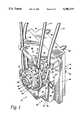
- FIG. 2is a front elevational view of the pump of FIG. 1.
- FIG. 3is a side elevational view of the pump of FIG. 1.
- FIG. 4is a side elevational view similar to FIG. 3, but showing the occlusion bed in open position.
- FIG. 5is an exploded perspective view of the pump of FIG. 1.
- FIG. 6is a rear elevational view of the pump of FIG. 1.
- the inventionis preferably embodied in a peristaltic pump 10 in which one or more lengths of tubing 12 are secured between a rotor 14 and an occlusion bed 16 such that rotation of the rotor 14 effects displacement of fluid therethrough.
- the occlusion bed 16is pivotally supported on a base 18 so that it is movable between an open position (FIG. 4) in which it is spaced from the rotor 14 sufficiently to permit loading and unloading of tubing, and a closed position (FIG. 3) in which the occlusion bed is spaced from the rotor by a relatively small distance to enable peristaltic pumping to take place.
- the occlusion bed 16pivots about a horizontal axis substantially perpendicular to the axis of the rotor 14.
- the occlusion bed 16 in the illustrated embodimentis a one-piece injection-molded structure comprising an occlusion surface 20 defining a predetermined radius for cooperation with the rotor 14 to effect pumping through the tubing 12, and further comprising a pair of integral hinge pins 22 extending outward on opposite sides thereof to support the occlusion bed for pivoting between its closed and open positions.
- Each of the hinge pins 22has a substantially circular cylindrical exterior over about three-quarters of its circumference, and is engaged by and supported in a respective slot 24 on the base 18.
- the occlusion bed 16preferably is formed with a plurality of rearwardly-opening cavities therein separated by ribs to reduce its mass and material requirements while providing stiffness and support for the occlusion surface.
- the illustrated pumpfurther comprises a lever-actuated snap-lock mechanism 26 for selectively maintaining the occlusion bed 16 in closed position during operation, while permitting manual release of the occlusion bed for displacement from the closed position to the open position when loading or unloading of tubing is desired.
- the lever-actuated snap-lock mechanism 26is disposed at the bottom of the occlusion bed, and comprises a flexible latch member 28 formed integrally with the occlusion bed and a fixed latch plate 36 on the base.
- the latch memberhas a generally L-shaped configuration, comprising a first wall 30 extending downward at the rear of the occlusion bed, and a second wall 32 extending forward from the bottom of the first wall and having a wedge-shaped protrusion 34 on the upper surface thereof for engaging the latch plate 36 on the base to cam the second wall 32 downward as the occlusion bed is pivoted to closed position, then lock the occlusion bed in closed position as the second wall 32 snaps upward.
- the usermanually deflects the second wall 32 of the latch member 28 downward, which releases the protrusion 34 from locking engagement with the latch plate 36 and additionally causes the occlusion bed to pivot toward the open position.
- the protrusion 34then engages the lower surface of the latch plate to limit pivoting of the occlusion bed, as shown in FIG. 4.
- a relatively high amount of additional forceis required to deflect the latch member 28 sufficiently to clear the rear edge of the latch plate 36 to permit the occlusion bed to be removed from the base.
- the occlusion bedcan be so removed by application of such force and, after the latch member 28 has cleared the latch plate 36, the occlusion bed may then be lifted so that the hinge pins 22 clear their associated slots 24, and the occlusion bed may then be moved forward out of association with the base, provided that the rotor has first been removed.
- the base 18comprises a generally rectangular frame comprising a top wall 38, a pair of sidewalls 40 extending downward therefrom, and a bottom strut 42 connecting the lower ends of the sidewalls.
- the base 18further comprises a front wall 44 which extends laterally beyond the sidewalls to define mounting flanges 46 for the base.
- the base 18includes integral vertical lugs 48 extending forward of the front wall, with upwardly opening slots 24 to receive the hinge pin.
- the latch plate 36extends between the lugs 48.
- the baseTo support the rotor shaft 50 for rotation on the base 18, the base includes an integral stationary collar 52 of generally cylindrical configuration extending rearward from the front wall 44. Reinforcing ribs 54 extend generally outward from the collar to provide sufficient stiffness to enable the collar to stably support the shaft and react against forces normal to the shaft resulting from the pressure between the rollers and the occlusion bed.
- the rotor 14is supported on a cantilevered portion of the shaft, which is unsupported at its forward end 56 opposite the front wall of the base.
- the base collar 52is preferably provided with a suitable bronze bushing 58 or a suitable bearing to avoid wear on its interior surface.
- the illustrated pumpmay be driven by a motor (not shown) disposed directly rearward of the base 18, and to facilitate attachment of the pump to a motor, four motor-mount bosses 60 are provided extending rearward from the base in a generally rectangular pattern near the corners thereof.
- the tubing retainer mechanismis configured to support two lengths of tubing 12 which may be disposed simultaneously in the pump.
- the tubing retainer mechanismcomprises upper and lower generally horizontal walls 62 and 63 extending forward from the front wall 44 of the base above the rotor. Each has a forward surface having forward and rear pairs of slots 64 and 66 formed along its front edge to receive the tubing.
- the lower wall 63is molded integrally with the base.
- the upper wall 62is provided with rearwardly-extending barbed protrusions 68 for insertion in openings 70 in the front wall 44 of the base for securement of the upper wall therein.
- forward and rear leaf springs 72 and 74are disposed between the upper and lower tubing retainer walls 62 and 63 with their ends positioned to urge the tubing into the slots 64 and 66.
- Each of the leaf springsis configured so that its ends may be individually pulled forward to enable tubing to be placed in engagement with the slot. Upon release, the ends of the springs urge the tubing into the slots and maintain it in place.
- a rib 76 depending from the upper wall 62extends laterally across the tubing retainer immediately rearward of the forward spring, and a second rib 78 is disposed immediately forward of the forward spring at or near the center thereof.
- the rear leaf spring 74is similarly constrained.
- Each of the leaf springsalso has an integral, upwardly-extending tab 80 received in an opening 82 in the upper wall to constrain it against lateral displacement.
- a relatively large opening 84is provided in the base 18 below the collar 52.
- the occlusion bedWhen the occlusion bed is pivoted to open position, its lower portion extends through the opening 84.
- the rotor 14 in the illustrated embodiment of the inventiongenerally comprises a plurality of rollers 86, the rotor shaft 50, and a pair of rotor members 94, each comprising an end plate 92, a plurality of roller support pins 88, and a collar 96 which has a noncircular bore for engagement with a complementary exterior surface of the shaft 50 to couple the rotor members 94 to the shaft for rotation therewith.
- each of the members 94is a one-piece, integral unit and has one-half of the rotor's roller support pins 88 integrally formed thereon.
- the members 94have substantially the same configuration, and each of the members 94 has three roller support pins 88 integrally formed therewith and equally spaced from one another at 120° intervals.
- Each of the end platesfurther has openings equally spaced, midway between each adjacent pair of support pins 88 to receive the ends of the pins formed on the opposite associated end plate.
- the rollers 86are in direct contact with their associated roller support pins 88, without bearings, bushings, or other components disposed between the roller and support pin.
- the rollers and support pinsare preferably manufactured from a composite material containing an internal lubricant such as polytetrafluoroethylene (PTFE).
- PTFEpolytetrafluoroethylene
- PPSpolyphenylenesulfide
- the entire pumpmay be made of this material, with the exception of the leaf springs 72 and 74, rotor shaft 50, bushing 58, and clip 98.
- the rotor shaft 50preferably has an integral collar 96 of enlarged diameter thereon to bear on the rear surface of the bushing 58 and limit forward travel of the shaft 50.
- a bore and set screw or other suitable meansmay be provided at the rear end of the shaft to facilitate coupling to a motor shaft.
- a clip 98may be disposed in a slot or groove at its forward end.
- the inventionprovides a novel and improved peristaltic pump.
- One feature of the illustrated pumpis the relatively small number of parts, which facilitates manufacture and assembly.
- the illustrated pump 10comprises only sixteen parts.
- the base 18is a one-piece, integral member, as is the occlusion bed 16.
- Eachmay be injection molded from a suitable composite material for high strength and light weight.
- each of the rotor members 94 and rollers 86is a one-piece, integral part which may be injection molded of a suitable composite material.
- the pumpmay be assembled relatively simply by the following steps:
- the occlusion bed 16is inserted rearward through the opening 84 in the front wall 44 of the base, and the hinge pins 22 are lowered into their associated slots 24 as the latch member 28 is flexed downward to enable it to slide past the rear edge of the latch plate 36.
- the bushing 58is inserted into the fixed collar 52 on the base from the rear, and the rotor shaft 50 is inserted through the bushing.
- the rollers 86are placed on the roller support pins 88 of their respective associated rotor members 94, and the rotor members 94 are thereafter snapped together, with the respective collars 96 abutting when the members 94 are in the proper assembled position relative to one another.
- the members 94are placed on the rotor shaft.
- the clipis placed on the forward end of the shaft.
- the upper tubing retainer plate, with the leaf springs properly positioned thereon,is snapped into place on the front wall.
- the above assembly proceduremay be contrasted with much longer and more complicated assembly procedures needed for many known prior art peristaltic pumps.
- the inventionprovides a pump which is not only capable of providing precise flow control over a relatively wide range of flow rates, but also is compact and economical to manufacture and assemble.
Landscapes
- Engineering & Computer Science (AREA)
- Mechanical Engineering (AREA)
- General Engineering & Computer Science (AREA)
- Reciprocating Pumps (AREA)
Abstract
Description
Claims (12)
Priority Applications (5)
| Application Number | Priority Date | Filing Date | Title |
|---|---|---|---|
| US08/123,807US5380173A (en) | 1993-09-20 | 1993-09-20 | Peristaltic pump |
| CA002132070ACA2132070C (en) | 1993-09-20 | 1994-09-14 | Peristaltic pump |
| EP94306818AEP0648509B1 (en) | 1993-09-20 | 1994-09-19 | Peristaltic pump |
| DE69422577TDE69422577T2 (en) | 1993-09-20 | 1994-09-19 | Peristaltic pump |
| JP6225180AJPH07151062A (en) | 1993-09-20 | 1994-09-20 | Peristaltic pump |
Applications Claiming Priority (1)
| Application Number | Priority Date | Filing Date | Title |
|---|---|---|---|
| US08/123,807US5380173A (en) | 1993-09-20 | 1993-09-20 | Peristaltic pump |
Publications (1)
| Publication Number | Publication Date |
|---|---|
| US5380173Atrue US5380173A (en) | 1995-01-10 |
Family
ID=22411009
Family Applications (1)
| Application Number | Title | Priority Date | Filing Date |
|---|---|---|---|
| US08/123,807Expired - Fee RelatedUS5380173A (en) | 1993-09-20 | 1993-09-20 | Peristaltic pump |
Country Status (5)
| Country | Link |
|---|---|
| US (1) | US5380173A (en) |
| EP (1) | EP0648509B1 (en) |
| JP (1) | JPH07151062A (en) |
| CA (1) | CA2132070C (en) |
| DE (1) | DE69422577T2 (en) |
Cited By (55)
| Publication number | Priority date | Publication date | Assignee | Title |
|---|---|---|---|---|
| WO1997010436A3 (en)* | 1995-09-15 | 1997-05-09 | Cobe Lab | Technique for loading a pump header within a peristaltic pump of a dialysis machine |
| US5630711A (en)* | 1995-09-08 | 1997-05-20 | Graymills Corporation | Peristaltic pump having a loop-shaped tube path |
| US5681294A (en)* | 1995-09-21 | 1997-10-28 | Abbott Laboratories | Fluid delivery set |
| US5688112A (en)* | 1996-02-22 | 1997-11-18 | Garay; Thomas William | Rotor axis aligned tube and outlet for a peristaltic pump system |
| US5846061A (en)* | 1996-11-08 | 1998-12-08 | Board Of Trustees Of Michigan State University | Peristaltic metering pump |
| USD403259S (en) | 1997-06-06 | 1998-12-29 | Miura Co., Ltd. | Colorimeter |
| USD403604S (en)* | 1997-09-29 | 1999-01-05 | Yoshitami Tsubota | Reagent cartridge for colorimeter |
| US6484594B1 (en)* | 1997-12-12 | 2002-11-26 | Research International, Inc. | High efficiency a wetted surface cyclonic air sampler |
| US20030055396A1 (en)* | 2000-05-12 | 2003-03-20 | Francis Goudaliez | Extraction device with tubes having different cross-sections |
| USD486501S1 (en) | 2001-10-13 | 2004-02-10 | Swagelok Company | Combined snap assembly actuator housing and mounting bracket |
| USD493870S1 (en) | 2002-05-31 | 2004-08-03 | Swagelok Company | Actuator handle |
| US20050069419A1 (en)* | 2003-09-29 | 2005-03-31 | Cull Laurence J. | Peristaltic pump with air venting via the movement of a pump head or a backing plate during surgery |
| US20050069437A1 (en)* | 2003-09-29 | 2005-03-31 | Michael Mittelstein | Peristaltic pump with a moveable pump head |
| US6874756B2 (en) | 2001-04-26 | 2005-04-05 | Swagelok Company | Snap assembly actuator housing and valve mounting bracket |
| US20060245964A1 (en)* | 2003-04-29 | 2006-11-02 | Loren Hagen | Pulseless peristaltic pump |
| US20070134113A1 (en)* | 2005-12-09 | 2007-06-14 | Industrial Technology Research Institute | Peristaltic pump |
| US20070219480A1 (en)* | 2006-02-09 | 2007-09-20 | Dean Kamen | Patch-sized fluid delivery systems and methods |
| US20070243088A1 (en)* | 2006-04-12 | 2007-10-18 | Cole-Parmer Instrument Company | Marked Tube For A Peristaltic Pump |
| US20090087325A1 (en)* | 2007-09-27 | 2009-04-02 | Voltenburg Jr Robert R | Peristaltic pump assembly and regulator therefor |
| US20090087327A1 (en)* | 2007-09-27 | 2009-04-02 | Voltenburg Jr Robert R | Peristaltic pump and removable cassette therefor |
| US20090087326A1 (en)* | 2007-09-27 | 2009-04-02 | Voltenburg Jr Robert R | Peristaltic pump assembly |
| US20090263256A1 (en)* | 2005-04-07 | 2009-10-22 | Bobo Marion H | Head for a peristaltic pump |
| US20090281497A1 (en)* | 2007-12-31 | 2009-11-12 | Dean Kamen | Wearable pump assembly |
| US20100301071A1 (en)* | 2007-12-05 | 2010-12-02 | Bunn-O-Matic Corporation | Peristaltic pump |
| US20110004161A1 (en)* | 2008-02-28 | 2011-01-06 | Jms Co., Ltd. | Injection device for semi-solidified nutritiional supplement |
| US8496646B2 (en) | 2007-02-09 | 2013-07-30 | Deka Products Limited Partnership | Infusion pump assembly |
| US20130287613A1 (en)* | 2010-10-07 | 2013-10-31 | Vanderbilt University | Peristaltic micropump and related systems and methods |
| US9072540B2 (en) | 2009-08-12 | 2015-07-07 | Boston Scientific Limited | Adaptive tubing cassettes for use in connection with interventional catheter assemblies |
| US9239049B2 (en) | 2010-07-16 | 2016-01-19 | Boston Scientific Limited | Peristaltic pump having a self-closing occlusion bed |
| WO2016161060A1 (en)* | 2015-04-03 | 2016-10-06 | Orczy-Timko Benedek | Surgical fluid management system |
| US9775964B2 (en) | 2009-08-12 | 2017-10-03 | Boston Scientific Limited | Interventional catheter assemblies, control consoles and adaptive tubing cassettes |
| EP3597914A1 (en)* | 2018-07-20 | 2020-01-22 | Cole-Parmer Instrument Company LLC | Tubing retention mechanism usable with a peristaltic pump |
| US10578096B2 (en) | 2016-06-30 | 2020-03-03 | Cole-Parmer Instrument Company Llc | Peristaltic pumphead and methods for assembly thereof |
| US11364335B2 (en) | 2006-02-09 | 2022-06-21 | Deka Products Limited Partnership | Apparatus, system and method for fluid delivery |
| US11395877B2 (en) | 2006-02-09 | 2022-07-26 | Deka Products Limited Partnership | Systems and methods for fluid delivery |
| US11404776B2 (en) | 2007-12-31 | 2022-08-02 | Deka Products Limited Partnership | Split ring resonator antenna adapted for use in wirelessly controlled medical device |
| US11426512B2 (en) | 2006-02-09 | 2022-08-30 | Deka Products Limited Partnership | Apparatus, systems and methods for an infusion pump assembly |
| US11478623B2 (en) | 2006-02-09 | 2022-10-25 | Deka Products Limited Partnership | Infusion pump assembly |
| US11497846B2 (en) | 2006-02-09 | 2022-11-15 | Deka Products Limited Partnership | Patch-sized fluid delivery systems and methods |
| US11497686B2 (en) | 2007-12-31 | 2022-11-15 | Deka Products Limited Partnership | Apparatus, system and method for fluid delivery |
| US11524151B2 (en) | 2012-03-07 | 2022-12-13 | Deka Products Limited Partnership | Apparatus, system and method for fluid delivery |
| US11523972B2 (en) | 2018-04-24 | 2022-12-13 | Deka Products Limited Partnership | Apparatus, system and method for fluid delivery |
| US11534542B2 (en) | 2007-12-31 | 2022-12-27 | Deka Products Limited Partnership | Apparatus, system and method for fluid delivery |
| US11597541B2 (en) | 2013-07-03 | 2023-03-07 | Deka Products Limited Partnership | Apparatus, system and method for fluid delivery |
| US11642283B2 (en) | 2007-12-31 | 2023-05-09 | Deka Products Limited Partnership | Method for fluid delivery |
| US11692540B2 (en) | 2017-11-08 | 2023-07-04 | Oina Vv Ab | Peristaltic pump |
| US11723841B2 (en) | 2007-12-31 | 2023-08-15 | Deka Products Limited Partnership | Apparatus, system and method for fluid delivery |
| US11786401B2 (en) | 2019-03-18 | 2023-10-17 | Verily Life Sciences Llc | Peristaltic micropump assemblies and associated devices, systems, and methods |
| US11890448B2 (en) | 2006-02-09 | 2024-02-06 | Deka Products Limited Partnership | Method and system for shape-memory alloy wire control |
| US11957365B2 (en) | 2020-11-20 | 2024-04-16 | Covidien Lp | Aspiration pulsator |
| US11964126B2 (en) | 2006-02-09 | 2024-04-23 | Deka Products Limited Partnership | Infusion pump assembly |
| US12064590B2 (en) | 2006-02-09 | 2024-08-20 | Deka Products Limited Partnership | Patch-sized fluid delivery systems and methods |
| US12070574B2 (en) | 2006-02-09 | 2024-08-27 | Deka Products Limited Partnership | Apparatus, systems and methods for an infusion pump assembly |
| US12151080B2 (en) | 2006-02-09 | 2024-11-26 | Deka Products Limited Partnership | Adhesive and peripheral systems and methods for medical devices |
| US12274857B2 (en) | 2006-02-09 | 2025-04-15 | Deka Products Limited Partnership | Method and system for shape-memory alloy wire control |
Families Citing this family (1)
| Publication number | Priority date | Publication date | Assignee | Title |
|---|---|---|---|---|
| US5954486A (en)* | 1997-07-01 | 1999-09-21 | Daiichi Techno Co., Ltd. | Squeeze pump having shrink fitter rollers |
Citations (15)
| Publication number | Priority date | Publication date | Assignee | Title |
|---|---|---|---|---|
| US3963023A (en)* | 1974-11-04 | 1976-06-15 | Cobe Laboratories, Inc. | Extracorporeal blood circulation system and pump |
| US4231725A (en)* | 1978-10-16 | 1980-11-04 | Cole-Parmer Instrument Company | Peristaltic pump |
| GB2051253A (en)* | 1979-06-15 | 1981-01-14 | Watson Marlow Ltd | Peristaltic fluid-machines |
| US4256442A (en)* | 1979-04-18 | 1981-03-17 | Baxter Travenol Laboratories, Inc. | Improved pressure plate movement system for a peristaltic pump |
| GB2075128A (en)* | 1980-04-28 | 1981-11-11 | Lkb Produkter Ab | A peristaltic pump |
| US4493706A (en)* | 1982-08-12 | 1985-01-15 | American Hospital Supply Corporation | Linear peristaltic pumping apparatus and disposable casette therefor |
| US4552516A (en)* | 1984-06-15 | 1985-11-12 | Cole-Parmer Instrument Company | Peristaltic pump |
| US4813855A (en)* | 1987-06-26 | 1989-03-21 | Tek-Aids Inc. | Peristaltic pump |
| US4886431A (en)* | 1988-04-29 | 1989-12-12 | Cole-Parmer Instrument Company | Peristaltic pump having independently adjustable cartridges |
| US5082429A (en)* | 1990-08-28 | 1992-01-21 | Cole-Parmer Instrument Company | Peristaltic pump |
| US5110270A (en)* | 1990-09-10 | 1992-05-05 | Morrick Joseph Q | Peristaltic pump with spring means to urge slide members and attached rollers radially outward on a rotor |
| US5133650A (en)* | 1990-06-15 | 1992-07-28 | Sherwood Medical Company | Infusion device rotor shield |
| US5147312A (en)* | 1990-06-15 | 1992-09-15 | Sherwood Medical Company | Peristaltic infusion device drip chamber yoke |
| US5230614A (en)* | 1992-06-03 | 1993-07-27 | Allergan, Inc. | Reduced pulsation tapered ramp pump head |
| US5266013A (en)* | 1990-03-23 | 1993-11-30 | Asulab S.A. | Portable pump for the administration of a therapeutic |
Family Cites Families (4)
| Publication number | Priority date | Publication date | Assignee | Title |
|---|---|---|---|---|
| US3839750A (en)* | 1972-11-10 | 1974-10-08 | Baker Hydro Inc | Weir hinge structure |
| FR2458694A1 (en)* | 1979-06-08 | 1981-01-02 | Lariviere Jean | Miniature peristaltic pump with electronic speed regulator - has DC motor rotating pump wheel having electronic speed control with variable potentiometer |
| GB2138511B (en)* | 1983-04-14 | 1987-03-25 | Smith & Nephew Ass | Peristaltic pump and pumphead therefor |
| US4573887A (en)* | 1983-09-16 | 1986-03-04 | S. E. Rykoff & Co. | Corrosion-resistant roller-type pump |
- 1993
- 1993-09-20USUS08/123,807patent/US5380173A/ennot_activeExpired - Fee Related
- 1994
- 1994-09-14CACA002132070Apatent/CA2132070C/ennot_activeExpired - Fee Related
- 1994-09-19EPEP94306818Apatent/EP0648509B1/ennot_activeExpired - Lifetime
- 1994-09-19DEDE69422577Tpatent/DE69422577T2/ennot_activeExpired - Fee Related
- 1994-09-20JPJP6225180Apatent/JPH07151062A/enactivePending
Patent Citations (15)
| Publication number | Priority date | Publication date | Assignee | Title |
|---|---|---|---|---|
| US3963023A (en)* | 1974-11-04 | 1976-06-15 | Cobe Laboratories, Inc. | Extracorporeal blood circulation system and pump |
| US4231725A (en)* | 1978-10-16 | 1980-11-04 | Cole-Parmer Instrument Company | Peristaltic pump |
| US4256442A (en)* | 1979-04-18 | 1981-03-17 | Baxter Travenol Laboratories, Inc. | Improved pressure plate movement system for a peristaltic pump |
| GB2051253A (en)* | 1979-06-15 | 1981-01-14 | Watson Marlow Ltd | Peristaltic fluid-machines |
| GB2075128A (en)* | 1980-04-28 | 1981-11-11 | Lkb Produkter Ab | A peristaltic pump |
| US4493706A (en)* | 1982-08-12 | 1985-01-15 | American Hospital Supply Corporation | Linear peristaltic pumping apparatus and disposable casette therefor |
| US4552516A (en)* | 1984-06-15 | 1985-11-12 | Cole-Parmer Instrument Company | Peristaltic pump |
| US4813855A (en)* | 1987-06-26 | 1989-03-21 | Tek-Aids Inc. | Peristaltic pump |
| US4886431A (en)* | 1988-04-29 | 1989-12-12 | Cole-Parmer Instrument Company | Peristaltic pump having independently adjustable cartridges |
| US5266013A (en)* | 1990-03-23 | 1993-11-30 | Asulab S.A. | Portable pump for the administration of a therapeutic |
| US5133650A (en)* | 1990-06-15 | 1992-07-28 | Sherwood Medical Company | Infusion device rotor shield |
| US5147312A (en)* | 1990-06-15 | 1992-09-15 | Sherwood Medical Company | Peristaltic infusion device drip chamber yoke |
| US5082429A (en)* | 1990-08-28 | 1992-01-21 | Cole-Parmer Instrument Company | Peristaltic pump |
| US5110270A (en)* | 1990-09-10 | 1992-05-05 | Morrick Joseph Q | Peristaltic pump with spring means to urge slide members and attached rollers radially outward on a rotor |
| US5230614A (en)* | 1992-06-03 | 1993-07-27 | Allergan, Inc. | Reduced pulsation tapered ramp pump head |
Non-Patent Citations (1)
| Title |
|---|
| Information regarding properties of plastic materials (author unknown; title unknown; date unknown; pp. 1, 2, 6, 13 and 14).* |
Cited By (126)
| Publication number | Priority date | Publication date | Assignee | Title |
|---|---|---|---|---|
| US5897300A (en)* | 1995-09-08 | 1999-04-27 | Graymills Corporation | Quick-release bolt for use with pump housing |
| US5630711A (en)* | 1995-09-08 | 1997-05-20 | Graymills Corporation | Peristaltic pump having a loop-shaped tube path |
| WO1997010436A3 (en)* | 1995-09-15 | 1997-05-09 | Cobe Lab | Technique for loading a pump header within a peristaltic pump of a dialysis machine |
| US5928177A (en)* | 1995-09-15 | 1999-07-27 | Cobe Laboratories, Inc. | Technique for loading a pump header within a peristaltic pump of a dialysis machine |
| US5681294A (en)* | 1995-09-21 | 1997-10-28 | Abbott Laboratories | Fluid delivery set |
| US5688112A (en)* | 1996-02-22 | 1997-11-18 | Garay; Thomas William | Rotor axis aligned tube and outlet for a peristaltic pump system |
| US5846061A (en)* | 1996-11-08 | 1998-12-08 | Board Of Trustees Of Michigan State University | Peristaltic metering pump |
| USD403259S (en) | 1997-06-06 | 1998-12-29 | Miura Co., Ltd. | Colorimeter |
| USD403604S (en)* | 1997-09-29 | 1999-01-05 | Yoshitami Tsubota | Reagent cartridge for colorimeter |
| US6484594B1 (en)* | 1997-12-12 | 2002-11-26 | Research International, Inc. | High efficiency a wetted surface cyclonic air sampler |
| US6532835B1 (en) | 1997-12-12 | 2003-03-18 | Research International, Inc. | High efficiency wetted surface cyclonic air sampler |
| US20030115975A1 (en)* | 1997-12-12 | 2003-06-26 | Research Intertional, Inc. | Air sampler |
| US7261008B2 (en) | 1997-12-12 | 2007-08-28 | Research International, Inc. | Air sampler |
| US20030055396A1 (en)* | 2000-05-12 | 2003-03-20 | Francis Goudaliez | Extraction device with tubes having different cross-sections |
| US7427278B2 (en)* | 2000-05-12 | 2008-09-23 | Macopharma | Extraction device with tubes having different cross-sections |
| US6874756B2 (en) | 2001-04-26 | 2005-04-05 | Swagelok Company | Snap assembly actuator housing and valve mounting bracket |
| USD486501S1 (en) | 2001-10-13 | 2004-02-10 | Swagelok Company | Combined snap assembly actuator housing and mounting bracket |
| USD493870S1 (en) | 2002-05-31 | 2004-08-03 | Swagelok Company | Actuator handle |
| USD511369S1 (en) | 2002-05-31 | 2005-11-08 | Swagelok Company | Manual valve actuator with cam |
| USD500842S1 (en) | 2002-05-31 | 2005-01-11 | Swagelok Company | Manual valve actuator with cam |
| US7645127B2 (en) | 2003-04-29 | 2010-01-12 | Loren Hagen | Pulseless peristaltic pump |
| US20060245964A1 (en)* | 2003-04-29 | 2006-11-02 | Loren Hagen | Pulseless peristaltic pump |
| US7168930B2 (en) | 2003-09-29 | 2007-01-30 | Bausch & Lomb Incorporated | Peristaltic pump with air venting via the movement of a pump head or a backing plate during surgery |
| US20050069419A1 (en)* | 2003-09-29 | 2005-03-31 | Cull Laurence J. | Peristaltic pump with air venting via the movement of a pump head or a backing plate during surgery |
| US20050069437A1 (en)* | 2003-09-29 | 2005-03-31 | Michael Mittelstein | Peristaltic pump with a moveable pump head |
| US7445436B2 (en) | 2003-09-29 | 2008-11-04 | Bausch & Lomb Incorporated | Peristaltic pump with a moveable pump head |
| US7918657B2 (en) | 2005-04-07 | 2011-04-05 | Bobo Marion H | Head for a peristaltic pump with guide and roller clamp arrangement |
| EP1869324A4 (en)* | 2005-04-07 | 2010-04-07 | Marion H Bobo | A head for peristaltic pump |
| US20090263256A1 (en)* | 2005-04-07 | 2009-10-22 | Bobo Marion H | Head for a peristaltic pump |
| US7866960B2 (en) | 2005-12-09 | 2011-01-11 | Industrial Technology Research Institute | Peristaltic pump |
| US20070134113A1 (en)* | 2005-12-09 | 2007-06-14 | Industrial Technology Research Institute | Peristaltic pump |
| US12036387B2 (en) | 2006-02-09 | 2024-07-16 | Deka Products Limited Partnership | Device to determine volume of fluid dispensed |
| US11534543B2 (en)* | 2006-02-09 | 2022-12-27 | Deka Products Limited Partnership | Method for making patch-sized fluid delivery systems |
| US12311143B2 (en) | 2006-02-09 | 2025-05-27 | Deka Products Limited Partnership | Adhesive and peripheral systems and methods for medical devices |
| US12151080B2 (en) | 2006-02-09 | 2024-11-26 | Deka Products Limited Partnership | Adhesive and peripheral systems and methods for medical devices |
| US12070574B2 (en) | 2006-02-09 | 2024-08-27 | Deka Products Limited Partnership | Apparatus, systems and methods for an infusion pump assembly |
| US11339774B2 (en) | 2006-02-09 | 2022-05-24 | Deka Products Limited Partnership | Adhesive and peripheral systems and methods for medical devices |
| US20070228071A1 (en)* | 2006-02-09 | 2007-10-04 | Dean Kamen | Fluid delivery systems and methods |
| US12064590B2 (en) | 2006-02-09 | 2024-08-20 | Deka Products Limited Partnership | Patch-sized fluid delivery systems and methods |
| US10639418B2 (en)* | 2006-02-09 | 2020-05-05 | Deka Products Limited Partnership | Patch-sized fluid delivery systems and methods |
| US20070219496A1 (en)* | 2006-02-09 | 2007-09-20 | Dean Kamen | Pumping fluid delivery systems and methods using force application assembly |
| US11364335B2 (en) | 2006-02-09 | 2022-06-21 | Deka Products Limited Partnership | Apparatus, system and method for fluid delivery |
| US20070219480A1 (en)* | 2006-02-09 | 2007-09-20 | Dean Kamen | Patch-sized fluid delivery systems and methods |
| US11992650B2 (en) | 2006-02-09 | 2024-05-28 | Deka Products Limited Partnership | Adhesive and peripheral systems and methods for medical devices |
| US11964126B2 (en) | 2006-02-09 | 2024-04-23 | Deka Products Limited Partnership | Infusion pump assembly |
| US11904134B2 (en) | 2006-02-09 | 2024-02-20 | Deka Products Limited Partnership | Patch-sized fluid delivery systems and methods |
| US20120209186A1 (en)* | 2006-02-09 | 2012-08-16 | Dean Kamen | Patch-sized fluid delivery systems and methods |
| US20120209239A1 (en)* | 2006-02-09 | 2012-08-16 | Gray Larry B | Patch-sized fluid delivery systems and methods |
| US20120209187A1 (en)* | 2006-02-09 | 2012-08-16 | Dean Kamen | Patch-sized fluid delivery systems and methods |
| US20120209198A1 (en)* | 2006-02-09 | 2012-08-16 | Gray Larry B | Patch-sized fluid delivery systems and methods |
| US20120209240A1 (en)* | 2006-02-09 | 2012-08-16 | Gray Larry B | Patch-sized fluid delivery systems and methods |
| US20120209193A1 (en)* | 2006-02-09 | 2012-08-16 | Gray Larry B | Patch-sized fluid delivery systems and methods |
| US20120209179A1 (en)* | 2006-02-09 | 2012-08-16 | Dean Kamen | Patch-sized fluid delivery systems and methods |
| US8414522B2 (en) | 2006-02-09 | 2013-04-09 | Deka Products Limited Partnership | Fluid delivery systems and methods |
| US11890448B2 (en) | 2006-02-09 | 2024-02-06 | Deka Products Limited Partnership | Method and system for shape-memory alloy wire control |
| US11786651B2 (en) | 2006-02-09 | 2023-10-17 | Deka Products Limited Partnership | Patch-sized fluid delivery system |
| US11395877B2 (en) | 2006-02-09 | 2022-07-26 | Deka Products Limited Partnership | Systems and methods for fluid delivery |
| US8545445B2 (en)* | 2006-02-09 | 2013-10-01 | Deka Products Limited Partnership | Patch-sized fluid delivery systems and methods |
| US11738139B2 (en) | 2006-02-09 | 2023-08-29 | Deka Products Limited Partnership | Patch-sized fluid delivery systems and methods |
| US11690952B2 (en) | 2006-02-09 | 2023-07-04 | Deka Products Limited Partnership | Pumping fluid delivery systems and methods using force application assembly |
| US8585377B2 (en) | 2006-02-09 | 2013-11-19 | Deka Products Limited Partnership | Pumping fluid delivery systems and methods using force application assembly |
| US8617107B2 (en)* | 2006-02-09 | 2013-12-31 | Deka Products Limited Partnership | Patch-sized fluid delivery systems and methods |
| US20140114282A1 (en)* | 2006-02-09 | 2014-04-24 | Deka Products Limited Partnership | Patch-Sized Fluid Delivery Systems and Methods |
| US8998850B2 (en) | 2006-02-09 | 2015-04-07 | Deka Products Limited Partnership | Adhesive and peripheral systems and methods for medical devices |
| US9033921B2 (en)* | 2006-02-09 | 2015-05-19 | Deka Products Limited Partnership | Patch-sized fluid delivery systems and methods |
| US11617826B2 (en) | 2006-02-09 | 2023-04-04 | Deka Products Limited Partnership | Patch-sized fluid delivery systems and methods |
| US11559625B2 (en) | 2006-02-09 | 2023-01-24 | Deka Products Limited Partnership | Patch-sized fluid delivery systems and methods |
| US9265879B2 (en)* | 2006-02-09 | 2016-02-23 | Deka Products Limited Partnership | Patch-sized fluid delivery systems and methods |
| US12274857B2 (en) | 2006-02-09 | 2025-04-15 | Deka Products Limited Partnership | Method and system for shape-memory alloy wire control |
| US9498587B2 (en)* | 2006-02-09 | 2016-11-22 | Deka Products Limited Partnership | Patch-sized fluid delivery systems and methods |
| US11497846B2 (en) | 2006-02-09 | 2022-11-15 | Deka Products Limited Partnership | Patch-sized fluid delivery systems and methods |
| US9623198B2 (en)* | 2006-02-09 | 2017-04-18 | Deka Products Limited Partnership | Patch-sized fluid delivery systems and methods |
| US9724461B2 (en)* | 2006-02-09 | 2017-08-08 | Deka Products Limited Partnership | Patch-sized fluid delivery systems and methods |
| US11478623B2 (en) | 2006-02-09 | 2022-10-25 | Deka Products Limited Partnership | Infusion pump assembly |
| US11426512B2 (en) | 2006-02-09 | 2022-08-30 | Deka Products Limited Partnership | Apparatus, systems and methods for an infusion pump assembly |
| US11413391B2 (en) | 2006-02-09 | 2022-08-16 | Deka Products Limited Partnership | Patch-sized fluid delivery systems and methods |
| US11408414B2 (en) | 2006-02-09 | 2022-08-09 | Deka Products Limited Partnership | Adhesive and peripheral systems and methods for medical devices |
| US10293117B2 (en)* | 2006-02-09 | 2019-05-21 | Deka Products Limited Partnership | Patch-sized fluid delivery systems and methods |
| US7874819B2 (en) | 2006-04-12 | 2011-01-25 | Cole-Parmer Instrument Company | Marked tube for a peristaltic pump |
| US20070243088A1 (en)* | 2006-04-12 | 2007-10-18 | Cole-Parmer Instrument Company | Marked Tube For A Peristaltic Pump |
| US8496646B2 (en) | 2007-02-09 | 2013-07-30 | Deka Products Limited Partnership | Infusion pump assembly |
| US20090087327A1 (en)* | 2007-09-27 | 2009-04-02 | Voltenburg Jr Robert R | Peristaltic pump and removable cassette therefor |
| US20090087325A1 (en)* | 2007-09-27 | 2009-04-02 | Voltenburg Jr Robert R | Peristaltic pump assembly and regulator therefor |
| US20090087326A1 (en)* | 2007-09-27 | 2009-04-02 | Voltenburg Jr Robert R | Peristaltic pump assembly |
| US7934912B2 (en) | 2007-09-27 | 2011-05-03 | Curlin Medical Inc | Peristaltic pump assembly with cassette and mounting pin arrangement |
| US8062008B2 (en) | 2007-09-27 | 2011-11-22 | Curlin Medical Inc. | Peristaltic pump and removable cassette therefor |
| US8083503B2 (en) | 2007-09-27 | 2011-12-27 | Curlin Medical Inc. | Peristaltic pump assembly and regulator therefor |
| US8550310B2 (en) | 2007-12-05 | 2013-10-08 | Bunn-O-Matic Corporation | Peristaltic pump |
| US20100301071A1 (en)* | 2007-12-05 | 2010-12-02 | Bunn-O-Matic Corporation | Peristaltic pump |
| US11701300B2 (en) | 2007-12-31 | 2023-07-18 | Deka Products Limited Partnership | Method for fluid delivery |
| US11723841B2 (en) | 2007-12-31 | 2023-08-15 | Deka Products Limited Partnership | Apparatus, system and method for fluid delivery |
| US11894609B2 (en) | 2007-12-31 | 2024-02-06 | Deka Products Limited Partnership | Split ring resonator antenna adapted for use in wirelessly controlled medical device |
| US9526830B2 (en) | 2007-12-31 | 2016-12-27 | Deka Products Limited Partnership | Wearable pump assembly |
| US11497686B2 (en) | 2007-12-31 | 2022-11-15 | Deka Products Limited Partnership | Apparatus, system and method for fluid delivery |
| US8414563B2 (en) | 2007-12-31 | 2013-04-09 | Deka Products Limited Partnership | Pump assembly with switch |
| US12415031B2 (en) | 2007-12-31 | 2025-09-16 | Deka Products Limited Partnership | Wearable pump assembly |
| US11534542B2 (en) | 2007-12-31 | 2022-12-27 | Deka Products Limited Partnership | Apparatus, system and method for fluid delivery |
| US8491570B2 (en) | 2007-12-31 | 2013-07-23 | Deka Products Limited Partnership | Infusion pump assembly |
| US20090299289A1 (en)* | 2007-12-31 | 2009-12-03 | Dean Kamen | Pump assembly with switch |
| US20090281497A1 (en)* | 2007-12-31 | 2009-11-12 | Dean Kamen | Wearable pump assembly |
| US11404776B2 (en) | 2007-12-31 | 2022-08-02 | Deka Products Limited Partnership | Split ring resonator antenna adapted for use in wirelessly controlled medical device |
| US11642283B2 (en) | 2007-12-31 | 2023-05-09 | Deka Products Limited Partnership | Method for fluid delivery |
| US12128006B2 (en) | 2007-12-31 | 2024-10-29 | Deka Products Limited Partnership | Apparatus, system and method for fluid delivery |
| US12121497B2 (en) | 2007-12-31 | 2024-10-22 | Deka Products Limited Partnership | Method for fluid delivery |
| US20110004161A1 (en)* | 2008-02-28 | 2011-01-06 | Jms Co., Ltd. | Injection device for semi-solidified nutritiional supplement |
| US9072540B2 (en) | 2009-08-12 | 2015-07-07 | Boston Scientific Limited | Adaptive tubing cassettes for use in connection with interventional catheter assemblies |
| US10632245B2 (en) | 2009-08-12 | 2020-04-28 | Boston Scientific Limited | Interventional catheter assemblies, control consoles and adaptive tubing cassettes |
| US9775964B2 (en) | 2009-08-12 | 2017-10-03 | Boston Scientific Limited | Interventional catheter assemblies, control consoles and adaptive tubing cassettes |
| US9925315B2 (en) | 2009-08-12 | 2018-03-27 | Boston Scientific Limited | Adaptive tubing cassettes for use in connection with interventional catheter assemblies |
| US9239049B2 (en) | 2010-07-16 | 2016-01-19 | Boston Scientific Limited | Peristaltic pump having a self-closing occlusion bed |
| US20130287613A1 (en)* | 2010-10-07 | 2013-10-31 | Vanderbilt University | Peristaltic micropump and related systems and methods |
| US11524151B2 (en) | 2012-03-07 | 2022-12-13 | Deka Products Limited Partnership | Apparatus, system and method for fluid delivery |
| US11597541B2 (en) | 2013-07-03 | 2023-03-07 | Deka Products Limited Partnership | Apparatus, system and method for fluid delivery |
| US12012241B2 (en) | 2013-07-03 | 2024-06-18 | Deka Products Limited Partnership | Apparatus, system and method for fluid delivery |
| WO2016161060A1 (en)* | 2015-04-03 | 2016-10-06 | Orczy-Timko Benedek | Surgical fluid management system |
| US9907901B2 (en) | 2015-04-03 | 2018-03-06 | Cirrus Technologies Ltd | Surgical fluid management system |
| US10662939B2 (en) | 2015-04-03 | 2020-05-26 | Cirrus Technologies Ltd. | Surgical fluid management system |
| CN107613916A (en)* | 2015-04-03 | 2018-01-19 | 席勒斯科技有限公司 | Surgical Fluid Management Systems |
| US10578096B2 (en) | 2016-06-30 | 2020-03-03 | Cole-Parmer Instrument Company Llc | Peristaltic pumphead and methods for assembly thereof |
| US11692540B2 (en) | 2017-11-08 | 2023-07-04 | Oina Vv Ab | Peristaltic pump |
| US12320348B2 (en) | 2017-11-08 | 2025-06-03 | Oina Vv Ab | Peristaltic pump |
| US11523972B2 (en) | 2018-04-24 | 2022-12-13 | Deka Products Limited Partnership | Apparatus, system and method for fluid delivery |
| EP3597914A1 (en)* | 2018-07-20 | 2020-01-22 | Cole-Parmer Instrument Company LLC | Tubing retention mechanism usable with a peristaltic pump |
| US11136973B2 (en)* | 2018-07-20 | 2021-10-05 | Cole-Parmer Instrument Company Llc | Tubing retention mechanism usable with a peristaltic pump |
| US11786401B2 (en) | 2019-03-18 | 2023-10-17 | Verily Life Sciences Llc | Peristaltic micropump assemblies and associated devices, systems, and methods |
| US11957365B2 (en) | 2020-11-20 | 2024-04-16 | Covidien Lp | Aspiration pulsator |
Also Published As
| Publication number | Publication date |
|---|---|
| DE69422577D1 (en) | 2000-02-17 |
| DE69422577T2 (en) | 2000-08-17 |
| EP0648509B1 (en) | 2000-01-12 |
| CA2132070C (en) | 2003-10-28 |
| EP0648509A3 (en) | 1995-06-28 |
| CA2132070A1 (en) | 1995-03-21 |
| JPH07151062A (en) | 1995-06-13 |
| EP0648509A2 (en) | 1995-04-19 |
Similar Documents
| Publication | Publication Date | Title |
|---|---|---|
| US5380173A (en) | Peristaltic pump | |
| US20250172135A1 (en) | Peristaltic pump | |
| EP3263898B1 (en) | Peristaltic pumphead and methods for assembly thereof | |
| EP0283614B1 (en) | Apparatus for pumping fluids through a tube | |
| US4725205A (en) | Peristaltic pump with cam action compensator | |
| EP0663529B1 (en) | Peristaltic pump tube loading assembly | |
| US5110270A (en) | Peristaltic pump with spring means to urge slide members and attached rollers radially outward on a rotor | |
| US8128384B2 (en) | Tube loading assembly for peristaltic pump | |
| JP3068132B2 (en) | Peristaltic pump | |
| CA1299952C (en) | Peristaltic pump cartridge | |
| CA2048287C (en) | Peristaltic pump | |
| US8430643B2 (en) | Volumetric fluidics pump method with translating shaft | |
| KR20100083796A (en) | Peristaltic pump assembly | |
| EP2195538A1 (en) | Peristaltic pump and removable cassette therefor | |
| EP0041802B1 (en) | Scroll type fluid displacement apparatus | |
| CA2199156C (en) | Fluid delivery system with mounting linkage | |
| US4674962A (en) | Peristaltic pump | |
| US5037274A (en) | Peristaltic apparatus and method for pumping and/or metering fluids | |
| US5673588A (en) | Infusion pump retraction mechanism | |
| US7281914B2 (en) | Variable capacity rotary compressor | |
| US20220389923A1 (en) | Peristaltic pump with one-piece pump body and facilitated assembly | |
| JP3776585B2 (en) | Axial piston pump or motor | |
| JP6512822B2 (en) | Tube pump | |
| US20240337257A1 (en) | Device for a linear peristaltic pump, rotor and linear peristaltic pump | |
| CN213575392U (en) | Sports mechanism and air conditioner |
Legal Events
| Date | Code | Title | Description |
|---|---|---|---|
| AS | Assignment | Owner name:COLE-PARMER INSTRUMENT COMPANY, ILLINOIS Free format text:ASSIGNMENT OF ASSIGNORS INTEREST;ASSIGNOR:HELLSTROM, STEVEN P.;REEL/FRAME:006703/0905 Effective date:19930908 | |
| FEPP | Fee payment procedure | Free format text:PAT HLDR NO LONGER CLAIMS SMALL ENT STAT AS SMALL BUSINESS (ORIGINAL EVENT CODE: LSM2); ENTITY STATUS OF PATENT OWNER: LARGE ENTITY | |
| FPAY | Fee payment | Year of fee payment:4 | |
| FEPP | Fee payment procedure | Free format text:PAYOR NUMBER ASSIGNED (ORIGINAL EVENT CODE: ASPN); ENTITY STATUS OF PATENT OWNER: LARGE ENTITY | |
| FPAY | Fee payment | Year of fee payment:8 | |
| AS | Assignment | Owner name:JPMORGAN CHASE BANK, NEW YORK Free format text:SECURITY AGREEMENT;ASSIGNORS:COLE-PARMER INSTRUMENT COMPANY;FISHER CLINICAL SERVICES INC.;FISHER HAMILTON L.L.C.;AND OTHERS;REEL/FRAME:014102/0001 Effective date:20030214 | |
| AS | Assignment | Owner name:DEUTSCHE BANK AG, NEW YORK BRANCH, NEW YORK Free format text:ASSIGNMENT OF ASSIGNORS INTEREST;ASSIGNOR:JP MORGAN CHASE BANK;REEL/FRAME:014830/0001 Effective date:20031203 | |
| AS | Assignment | Owner name:COLE-PARMER INSTRUMENT COMPANY, ILLINOIS Free format text:RELEASE OF SECURITY INTEREST;ASSIGNOR:DEUTSCHE BANK AG NEW YORK BRANCH;REEL/FRAME:015748/0565 Effective date:20040802 Owner name:FISHER CLINICAL SERVICES INC., PENNSYLVANIA Free format text:RELEASE OF SECURITY INTEREST;ASSIGNOR:DEUTSCHE BANK AG NEW YORK BRANCH;REEL/FRAME:015748/0565 Effective date:20040802 Owner name:FISHER HAMILTON, L.L.C., WISCONSIN Free format text:RELEASE OF SECURITY INTEREST;ASSIGNOR:DEUTSCHE BANK AG NEW YORK BRANCH;REEL/FRAME:015748/0565 Effective date:20040802 Owner name:FISHER SCIENTIFIC COMPANY L.L.C., PENNSYLVANIA Free format text:RELEASE OF SECURITY INTEREST;ASSIGNOR:DEUTSCHE BANK AG NEW YORK BRANCH;REEL/FRAME:015748/0565 Effective date:20040802 Owner name:ERIE SCIENTIFIC COMPANY, NEW HAMPSHIRE Free format text:RELEASE OF SECURITY INTEREST;ASSIGNOR:DEUTSCHE BANK AG NEW YORK BRANCH;REEL/FRAME:015748/0565 Effective date:20040802 | |
| REMI | Maintenance fee reminder mailed | ||
| LAPS | Lapse for failure to pay maintenance fees | ||
| STCH | Information on status: patent discontinuation | Free format text:PATENT EXPIRED DUE TO NONPAYMENT OF MAINTENANCE FEES UNDER 37 CFR 1.362 | |
| FP | Lapsed due to failure to pay maintenance fee | Effective date:20070110 |