US5380159A - Pressure compensation device for high-pressure liquid pump - Google Patents
Pressure compensation device for high-pressure liquid pumpDownload PDFInfo
- Publication number
- US5380159A US5380159AUS08/261,693US26169394AUS5380159AUS 5380159 AUS5380159 AUS 5380159AUS 26169394 AUS26169394 AUS 26169394AUS 5380159 AUS5380159 AUS 5380159A
- Authority
- US
- United States
- Prior art keywords
- pin
- outlet
- lever
- inlet
- fluid
- Prior art date
- Legal status (The legal status is an assumption and is not a legal conclusion. Google has not performed a legal analysis and makes no representation as to the accuracy of the status listed.)
- Expired - Lifetime
Links
Images


Classifications
- F—MECHANICAL ENGINEERING; LIGHTING; HEATING; WEAPONS; BLASTING
- F04—POSITIVE - DISPLACEMENT MACHINES FOR LIQUIDS; PUMPS FOR LIQUIDS OR ELASTIC FLUIDS
- F04B—POSITIVE-DISPLACEMENT MACHINES FOR LIQUIDS; PUMPS
- F04B49/00—Control, e.g. of pump delivery, or pump pressure of, or safety measures for, machines, pumps, or pumping installations, not otherwise provided for, or of interest apart from, groups F04B1/00 - F04B47/00
- F04B49/22—Control, e.g. of pump delivery, or pump pressure of, or safety measures for, machines, pumps, or pumping installations, not otherwise provided for, or of interest apart from, groups F04B1/00 - F04B47/00 by means of valves
- F04B49/24—Bypassing
- F04B49/243—Bypassing by keeping open the inlet valve
Definitions
- This inventionrelates to high-pressure, positive displacement liquid pumps, and more particularly, to such pumps including means for controlling the output pressure of the pump.
- Numerous tasksmay be accomplished through the use of a stream of pressurized fluid, typically water, which is generated by high-pressure, positive displacement pumps.
- pressurized fluidtypically water
- Such pumpspressurize a fluid by having a reciprocating plunger that draws the fluid from an inlet area into a pressurization chamber during an intake stroke, and acts against the fluid during a pumping stroke, thereby forcing pressurized fluid to pass from the pressurization chamber through a passageway to an outlet check valve which selectively allows the pressurized fluid to pass into an outlet chamber.
- the pressurized fluid in the outlet chamberis then collected in a manifold to be used by an operator via whatever tool has been attached to the pump for a particular task.
- the required flow ratewill vary from the maximum the pump can supply to zero, for example, when the operator turns the tool off.
- the pressure in the outlet chamberwill build up beyond an acceptable level unless some form of pressure control is incorporated into the pump. If no pressure control is provided, the buildup of high pressure will result in damage and stress to the parts of the pump and undesirable surges of pressure will occur when the operator again turns the tool on.
- One method of pressure control which is currently usedis to incorporate a relief valve into the pump. When the pressure in the outlet chamber rises above a preset limit as a result of pressurizing more water than is demanded by the end user, the relief valve opens to vent the excess pressurized fluid.
- This methodhas several disadvantages, however. Perhaps most significantly, it is very expensive and inefficient to pressurize water thereby generating potential energy, only to throw it away. This throwing away of energy results in increased maintenance and fuel costs. This method of controlling output pressure is also undesirable because of the large quantity of water that is thrown away as waste, rather than being used.
- Another method considered in the course of developing the present invention for controlling the output pressure of the pump, which is substantially equivalent to the pressure in the outlet chamber,is to choke off the flow at the inlet.
- this methodcauses the fluid to cavitate, which results in significant damage to the pump.
- damagein turn increases the "down time" of the machine and increases cost of operation, both in labor and replacement parts.
- This methodalso causes the system to have a large time constant, which results in undesirable pressure oscillations.
- a high-pressure pumphaving a pressure compensation device.
- a high-pressure pumpis provided having the same elements and operating in the same manner as described above, which detects a force generated by high-pressure fluid in the outlet chamber and balances this force against a reference, or control force.
- the reference forceis generated by the use of a reference gas or fluid pressure acting over a piston of defined surface area.
- the control forcemay be generated by a spring or other mechanical mechanism, an electrical device or any other method of force generation.
- the pressure compensation deviceforces the inlet check valve open which allows the fluid in the pressurization chamber to flow back out of the pressurization chamber into the inlet area, thereby preventing the pressurization of any unneeded fluid.
- the pressure compensation devicehas three pins, an outlet pin, an inlet pin, and a compensation pin, each of the three pins having a first and a second end.
- the first end of the outlet pinis in contact with and therefore acted upon by the pressurized fluid in the outlet chamber. This action causes the second end of the outlet pin to exert a force against a lever of the compensation device.
- This force generated by the pressurized fluidis balanced by a force generated by the action of a control pressure acting against the first end of the compensation pin, which causes the second end of the compensation pin to exert a force on the lever.
- the geometry of the pressure compensation deviceis such that the pressure in the outlet chamber must be several magnitudes greater than the control pressure to balance the lever.
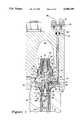
- FIG. 1is a cross-sectional top plan view of a preferred embodiment of the present invention illustrating a pressure compensation device incorporated into a high-pressure pump under conditions where the output pressure has not exceeded a desired level.
- FIG. 2is a cross-sectional top plan view of the pressure compensation device of FIG. 1 under conditions where the output pressure has exceeded a desired level.
- FIG. 3is a top plan view of a pump assembly utilizing three of the high-pressure pump heads and compensation devices shown in FIGS. 1 and 2.
- FIG. 4is a cross-sectional plan view taken on line 4--4 of FIG. 3.
- FIG. 5is a cross-sectional plan view of an alternative embodiment of the pressure compensation device of FIG. 1.
- FIG. 6is an enlarged cross-sectional plan view of an element of the pressure compensation device of FIG. 5.
- FIGS. 1 and 4illustrate a preferred embodiment of the present invention.
- a direct drive motor(not shown) causes a plunger 54 of a high-pressure pump, or pump head 12 to reciprocate within a pressurization chamber 18.
- the action of the reciprocating plunger 54will cause fluid to be drawn into the pressurization chamber 18 during an intake stroke and to be pressurized and forced out of the pressurization chamber 18 into an outlet chamber 20 during a pumping stroke.
- the pressurized fluidis selectively allowed to pass from the pressurization chamber 18 to the outlet chamber 20 by a valve assembly 64, having an inlet check valve 14 and an outlet check valve 13 connected via a passageway 66.
- the pressurized fluidpasses from the outlet chamber 20 to a manifold 80, where it is collected for use by an operator.
- a pressure compensation device 10which senses the pressure in the outlet chamber 20 and balances a force generated by this pressure against a resultant force from a fluid control pressure 36, the geometry of the pressure compensation device 10 being such as to allow a fluid control pressure 36 to balance a pressure in the outlet chamber 20 that is several magnitudes larger.
- the pressure compensation device 10acts to prevent further pressurization of fluid in the pressurization chamber 18 by causing the fluid in the pressurization chamber 18 to flow back out of the pressurization chamber 18 via a plurality of inlet ports 60 through which the fluid was originally introduced into the system.
- the high-pressure pump 12has a plunger 54 which reciprocates within a cylinder 94, the plunger 54 having an intake stroke and a pumping stroke, the direction of the two strokes being represented schematically in FIGS. 1 and 2 by arrows 56 and 58, respectively.
- the high-pressure pump 12further includes a valve assembly 64, comprised of an inlet check valve 14 and an outlet check valve 13, the two check valves 13 and 14 being connected via a passageway 66.
- the valve assembly 64is substantially contained within a check valve body 19 and a cap seal assembly 21, the cap seal assembly 21 being held against the valve body 19 by compression spring 27.
- the inlet check valve 14includes a valve element 11 and an inlet retaining screw 90 which allows limited movement of the valve element 11.
- the passageway 66extends through the inlet retaining screw 90 into a pressurization chamber 18.
- the inlet check valve 14is urged into a closed position by the inlet compression spring 88.
- the outlet check valve 13includes a poppet 72 and a poppet guide 74 which restricts the movement of the poppet 72.
- the poppet guide 74is mounted within a cage 23, and the outlet check valve 13 is urged into a closed position by outlet compression spring 92.
- the inlet check valve 14is pulled into an open position to a sufficient degree to allow a volume of fluid, typically water, being provided via the supply pipe 68, shown in FIG. 4, to pass through the inlet area 70 and through the inlet ports 60 into the pressurization chamber 18.
- the fluidis at a relatively low pressure, for example, 100-300 PSI.
- inlet ports 60may be used, including only one, in the preferred embodiment illustrated herein, five inlet ports 60 provide fluid to the pressurization chamber 18, the inlet ports 60 being spaced radially around the passageway 66.
- the plunger 54acts against the fluid, thereby compressing, or pressurizing it and forcing it towards the inlet check valve 14.
- the inlet check valve 14is forced into a closed position such that it closes off the inlet ports 60.
- the now pressurized fluidpasses through passageway 66 to the outlet check valve 13, where the pressure increases until it is sufficient to open the poppet 72 of the outlet check valve 13.
- the pressure developedmay be up to and beyond 40,000 PSI.
- the pressurized fluidthen flows around poppet 72 through discharge ports 76 and through outlet compression spring 92 into the outlet chamber 20. From outlet chamber 20, the pressurized fluid passes through the discharge pipe 78 to a manifold 80, shown in FIG.
- FIG. 3A pump assembly 96, utilizing three high-pressure pump heads 12 as illustrated in FIGS. 1 and 2, is illustrated in FIG. 3.
- FIG. 2shows the configuration of the pressure compensation device 10 under an operating condition where the pressure in the outlet chamber 20 has exceeded a desired level.
- the pressure compensation device 10has a lever 28 which pivots about a knife-edge bearing 46.
- the knife-edge bearing 46is preferably used in this environment because pressure control can be optimized by minimizing the friction between the machine elements.
- the pressure compensation device 10further includes three pins, namely a compensation pin 30, an outlet pin 22, and an inlet pin 38.
- the three pins 30, 22 and 38all preferably act on the center line of the lever 28 because by doing so, undesirable lateral movement of the pin ends perpendicular to the pin centerlines is minimized.
- the first end 24 of the outlet pin 22passes through an opening 25 in the check valve body 19 such that the outlet pin 22 is exposed to the pressurized fluid in the outlet chamber 20.
- the first end 24 of outlet pin 22is no more than 1-1.5 ten-thousandths of an inch smaller than the opening 25 in the check valve body 19 to prevent the leakage of pressurized fluid from the outlet chamber 20.
- This action of the pressurized fluid against the first end 24 of the outlet pin 22causes the second end 26 of the outlet pin 22 to exert a force against the lever 28 at a point 15. As illustrated in FIGS.
- the second end 26 of the outlet pin 22is preferably a knife-edge chisel 44, which serves to reduce friction between the outlet pin 22 and the lever 28, thereby optimizing pressure control as discussed above. It will be appreciated by one of ordinary skill in the art that the second end 26 of the outlet pin 22 may be formed into a knife-edge bearing or chisel or attached to a separately formed knife-edge chisel.
- outlet pin 22is contained within compensator actuator cartridge 104.
- cartridge 104is held in place by cage 113 and includes sleeve 105 through which outlet pin 22 passes.
- a seal 106is provided between the sleeve 105 and check valve body 19 to prevent any leakage at that interface.
- the interface between check valve body 19 and the end capis sealed by split keeper ring 109, o-ring 110, polymer seal 111 and a back up ring 112.
- outlet pin 22By containing outlet pin 22 in cartridge 104, manufacturing is simplified and precise tolerances may be achieved between the outer diameter of the outlet pin and the inner diameter of the sleeve 105. This is critical to prevent leakage of pressurized fluid from the outlet chamber 20, because leakage from the system increases dramatically with even minor increases in tolerances.
- the assemblyis easily replaceable.
- a spring 108maintains the outlet pin 22 and knife edge chisel 44 in proper position relative to each other and lever 28, and a filter 107 is provided to prevent contaminants in the pressurized fluid from reaching the interface between the outlet pin 22 and sleeve 105.
- the filteris made of sintered stainless steel.
- the first end 32 of the compensation pin 30is acted upon by a fluid control pressure 36 through compensation port 86.
- the fluid control pressure 36exerts a force against the diaphragm 82 and piston 84, causing the second end 34 of the compensation pin 30 to exert a control force against the lever 28 at point 17.
- the geometry of the pressure compensation device 10is such that the lever 28 will be balanced when the pressure in the outlet chamber 20 is 500 times the control pressure exerted on the diaphragm 82.
- the force generated by the pressurized fluid in the outlet chamber 20may also be balanced by a direct control force (not shown) rather than by a fluid control pressure 36 acting on a piston 84.
- a direct control forcemay be generated, for example, by a spring or other mechanical mechanism, an electrical device or any other method of force generation.
- a direct control forceis generated by spring actuator 100, wherein a spring 101 is used to apply a force through piston 102, causing compensation pin 30 to exert a control force against the lever 28.
- the spring forcemay be adjusted by rotating cap 103.
- the second end 34 of the compensation pin 30is preferably narrowed such that it is not in contact with the opening 52 provided in the lever 28 to receive the compensation pin 30 because by doing so, the compensation pin 30 is free to flex sufficiently as the lever 28 rotates to prevent the compensation pin 30 from sliding against lever 28. This design further serves to reduce friction and improve pressure control.
- the fluid control pressure 36may be provided by any suitable fluid, for example, water or air, and may be adjusted by the operator with the turn of a knob. Adjusting the control pressure therefore "sets" the output pressure given that a different control pressure requires a different pressure in the outlet chamber 20 to balance the lever. For example, if the fluid control pressure 36 is set to 80 PSI at compensation port 22, a fluid pressure of 40,000 PSI in the outlet chamber 20 acting on outlet pin 22 will balance the lever 28. It will be appreciated by one of ordinary skill in the art, that the geometry may be changed to result in a mechanical advantage of different ratios, for example, 400:1, meaning that a fluid control pressure 36 of 80 PSI would require a fluid pressure of 32,000 PSI in the outlet chamber 20 to balance the lever 28. In the preferred embodiment, however, as noted above, the mechanical advantage is set for 500:1.
- the pressure in the outlet chamber 20is "set" at 40,000 PSI by a fluid control pressure 36 of 80 PSI, and the pressure in the outlet chamber 20 has exceeded 40,000 PSI, for example if the operator has turned the tool he is using off.
- the force generated by the action of the pressurized fluid in the outlet chamber 20 acting on the first end 24 of the outlet pin 22will overcome the control force generated by the action of the fluid control pressure 36 acting on the first end 32 of the compensation pin 30.
- the lever 28will pivot about knife-edge bearing 46 in a counterclockwise direction, as illustrated in FIG. 2, thereby pushing on the first end 40 of the inlet pin 38.
- the second end 42 of the inlet pin 38which is in contact with the valve element 11 of the inlet check valve 14, will force the inlet check valve 14 into an open position, or, if the inlet check valve is already open, as it is during the intake stroke 56 of the plunger 54, the second end 42 of the inlet pin 38 will act as a stop, thereby preventing the inlet check valve 14 from closing.
- the fluid which is forced toward the inlet check valve 14 by the plunger 54 during its pumping stroke 58will flow back out of the pressurization chamber 18 through the inlet ports 60, rather than through the passageway 66 towards the outlet chamber 20.
- the pressure in the outlet chamber 20is therefore maintained at a substantially constant level, without throwing away water or potential energy. As long as the force generated by the pressurized fluid in the outlet chamber 20 is sufficient to overcome the control force, the inlet check valve 14 will be forced into an open position.
- recirculation of fluid to prevent pressurization of unneeded fluidis achieved by holding open the inlet check valve 14 thereby causing the fluid in the pressurization chamber 18 to flow back out into the inlet area 70
- the same resultsmay be achieved by allowing the fluid in the pressurization chamber 18 to flow into an alternative chamber or passageway to subsequently be recirculated through the inlet area 70.
- Similar results of the inventive concept described hereinmay also be accomplished by forcing the outlet check valve 13 open when the pressure in the outlet chamber 20 exceeds a desired level, thereby allowing pressurized fluid to escape from the outlet chamber 20 to be recirculated.
- the preferred embodiment of the pressure compensation device described hereinhas a fast response rate, or low time constant, enabling it to adjust for changes in pressure within 1/3 of a revolution of the pump. This arrangement is believed advantageous for most applications because a fast response rate further serves to optimize pressure control accuracy.
Landscapes
- Engineering & Computer Science (AREA)
- Mechanical Engineering (AREA)
- General Engineering & Computer Science (AREA)
- Details Of Reciprocating Pumps (AREA)
- Control Of Positive-Displacement Pumps (AREA)
Abstract
Description
Claims (27)
Priority Applications (1)
| Application Number | Priority Date | Filing Date | Title |
|---|---|---|---|
| US08/261,693US5380159A (en) | 1992-08-17 | 1994-06-16 | Pressure compensation device for high-pressure liquid pump |
Applications Claiming Priority (3)
| Application Number | Priority Date | Filing Date | Title |
|---|---|---|---|
| US93178092A | 1992-08-17 | 1992-08-17 | |
| US7358493A | 1993-06-07 | 1993-06-07 | |
| US08/261,693US5380159A (en) | 1992-08-17 | 1994-06-16 | Pressure compensation device for high-pressure liquid pump |
Related Parent Applications (1)
| Application Number | Title | Priority Date | Filing Date |
|---|---|---|---|
| US7358493AContinuation | 1992-08-17 | 1993-06-07 |
Publications (1)
| Publication Number | Publication Date |
|---|---|
| US5380159Atrue US5380159A (en) | 1995-01-10 |
Family
ID=26754642
Family Applications (1)
| Application Number | Title | Priority Date | Filing Date |
|---|---|---|---|
| US08/261,693Expired - LifetimeUS5380159A (en) | 1992-08-17 | 1994-06-16 | Pressure compensation device for high-pressure liquid pump |
Country Status (3)
| Country | Link |
|---|---|
| US (1) | US5380159A (en) |
| EP (1) | EP0583779B1 (en) |
| DE (1) | DE69317080T2 (en) |
Cited By (14)
| Publication number | Priority date | Publication date | Assignee | Title |
|---|---|---|---|---|
| US6162031A (en)* | 1998-10-30 | 2000-12-19 | Flow International Corporation | Seal seat for high pressure pumps and vessels |
| US20030172972A1 (en)* | 2002-03-06 | 2003-09-18 | Ingersoll-Rand Company | Replaceable check valve seats |
| US20040079416A1 (en)* | 2002-10-29 | 2004-04-29 | Ford Motor Company | Method and apparatus for metering a fluid |
| US20040108000A1 (en)* | 2002-12-06 | 2004-06-10 | Flow International Corporation | Ultrahigh-pressure check valve |
| US20060182640A1 (en)* | 2005-02-17 | 2006-08-17 | Slack And Parr Technologies Llc | High pressure pump |
| US20070009367A1 (en)* | 2005-04-21 | 2007-01-11 | Kmt Waterjet Systems, Inc. | Close fit cylinder and plunger |
| US20080245569A1 (en)* | 2006-12-28 | 2008-10-09 | Schlumberger Technology Corporation | Apparatus and Methods to Perform Focused Sampling of Reservoir Fluid |
| US20100040486A1 (en)* | 2005-02-17 | 2010-02-18 | Kinemax Pump Systems Llc | High pressure pump |
| US20140087631A1 (en)* | 2012-08-16 | 2014-03-27 | Omax Corporation | Control valves for waterjet systems and related devices, systems, and methods |
| US9095955B2 (en) | 2012-08-16 | 2015-08-04 | Omax Corporation | Control valves for waterjet systems and related devices, systems and methods |
| US11554461B1 (en) | 2018-02-13 | 2023-01-17 | Omax Corporation | Articulating apparatus of a waterjet system and related technology |
| US11904494B2 (en) | 2020-03-30 | 2024-02-20 | Hypertherm, Inc. | Cylinder for a liquid jet pump with multi-functional interfacing longitudinal ends |
| US12051316B2 (en) | 2019-12-18 | 2024-07-30 | Hypertherm, Inc. | Liquid jet cutting head sensor systems and methods |
| US12064893B2 (en) | 2020-03-24 | 2024-08-20 | Hypertherm, Inc. | High-pressure seal for a liquid jet cutting system |
Families Citing this family (1)
| Publication number | Priority date | Publication date | Assignee | Title |
|---|---|---|---|---|
| US6164930A (en)* | 1998-06-18 | 2000-12-26 | Flow International Corporation | Apparatus for regulating flow of a pumped substance |
Citations (17)
| Publication number | Priority date | Publication date | Assignee | Title |
|---|---|---|---|---|
| US985013A (en)* | 1909-12-27 | 1911-02-21 | Nickel Mfg Company | Air-pump. |
| US1819691A (en)* | 1930-05-07 | 1931-08-18 | Austin J Rix | Air compressor |
| US2065199A (en)* | 1933-03-25 | 1936-12-22 | Westinghouse Air Brake Co | Unloader governor device |
| US2155236A (en)* | 1937-09-14 | 1939-04-18 | Westinghouse Air Brake Co | Compressor unloading device |
| US2893625A (en)* | 1958-04-07 | 1959-07-07 | Bendix Westinghouse Automotive | Anti-freeze control mechanism |
| US2917225A (en)* | 1952-09-06 | 1959-12-15 | Carrier Corp | Capacity control for reciprocating compressors |
| US2971690A (en)* | 1958-10-24 | 1961-02-14 | Worthington Corp | Unloading means for a reciprocating compressor |
| US3043496A (en)* | 1958-11-12 | 1962-07-10 | Westinghouse Air Brake Co | Means and method of inhibiting the rise of the temperature of compressor cylinder incidental to operation while unloaded |
| US3166236A (en)* | 1961-06-23 | 1965-01-19 | Vilter Manufacturing Corp | Reciprocating piston type gas compressor |
| US4026322A (en)* | 1976-02-11 | 1977-05-31 | Flow Industries, Inc. | Reciprocating pump check valve assembly |
| WO1982003337A1 (en)* | 1981-04-03 | 1982-10-14 | Inc Cryomec | Unloading system for cryogenic pumps |
| US4371001A (en)* | 1977-10-31 | 1983-02-01 | Flow Industries, Inc. | Check valve assembly |
| US4389168A (en)* | 1981-03-27 | 1983-06-21 | Carrier Corporation | Apparatus for modulating the capacity of a reciprocating compressor |
| US4536135A (en)* | 1982-09-27 | 1985-08-20 | Flow Industries, Inc. | High pressure liquid piston pump |
| US4960340A (en)* | 1987-01-23 | 1990-10-02 | Kabushiki Kaisha Sakurakurepasu | Implement for applying liquid |
| US5037277A (en)* | 1989-07-26 | 1991-08-06 | Flow International Corporation | Poppet valve for a high pressure fluid pump |
| EP0484762A1 (en)* | 1990-11-06 | 1992-05-13 | FAIP S.r.L. OFFICINE MECCANICHE | Twin piston, commutator motor driven, high pressure pump for hydrocleaning equipment |
- 1993
- 1993-08-17EPEP93113179Apatent/EP0583779B1/ennot_activeExpired - Lifetime
- 1993-08-17DEDE69317080Tpatent/DE69317080T2/ennot_activeExpired - Fee Related
- 1994
- 1994-06-16USUS08/261,693patent/US5380159A/ennot_activeExpired - Lifetime
Patent Citations (17)
| Publication number | Priority date | Publication date | Assignee | Title |
|---|---|---|---|---|
| US985013A (en)* | 1909-12-27 | 1911-02-21 | Nickel Mfg Company | Air-pump. |
| US1819691A (en)* | 1930-05-07 | 1931-08-18 | Austin J Rix | Air compressor |
| US2065199A (en)* | 1933-03-25 | 1936-12-22 | Westinghouse Air Brake Co | Unloader governor device |
| US2155236A (en)* | 1937-09-14 | 1939-04-18 | Westinghouse Air Brake Co | Compressor unloading device |
| US2917225A (en)* | 1952-09-06 | 1959-12-15 | Carrier Corp | Capacity control for reciprocating compressors |
| US2893625A (en)* | 1958-04-07 | 1959-07-07 | Bendix Westinghouse Automotive | Anti-freeze control mechanism |
| US2971690A (en)* | 1958-10-24 | 1961-02-14 | Worthington Corp | Unloading means for a reciprocating compressor |
| US3043496A (en)* | 1958-11-12 | 1962-07-10 | Westinghouse Air Brake Co | Means and method of inhibiting the rise of the temperature of compressor cylinder incidental to operation while unloaded |
| US3166236A (en)* | 1961-06-23 | 1965-01-19 | Vilter Manufacturing Corp | Reciprocating piston type gas compressor |
| US4026322A (en)* | 1976-02-11 | 1977-05-31 | Flow Industries, Inc. | Reciprocating pump check valve assembly |
| US4371001A (en)* | 1977-10-31 | 1983-02-01 | Flow Industries, Inc. | Check valve assembly |
| US4389168A (en)* | 1981-03-27 | 1983-06-21 | Carrier Corporation | Apparatus for modulating the capacity of a reciprocating compressor |
| WO1982003337A1 (en)* | 1981-04-03 | 1982-10-14 | Inc Cryomec | Unloading system for cryogenic pumps |
| US4536135A (en)* | 1982-09-27 | 1985-08-20 | Flow Industries, Inc. | High pressure liquid piston pump |
| US4960340A (en)* | 1987-01-23 | 1990-10-02 | Kabushiki Kaisha Sakurakurepasu | Implement for applying liquid |
| US5037277A (en)* | 1989-07-26 | 1991-08-06 | Flow International Corporation | Poppet valve for a high pressure fluid pump |
| EP0484762A1 (en)* | 1990-11-06 | 1992-05-13 | FAIP S.r.L. OFFICINE MECCANICHE | Twin piston, commutator motor driven, high pressure pump for hydrocleaning equipment |
Cited By (25)
| Publication number | Priority date | Publication date | Assignee | Title |
|---|---|---|---|---|
| US6162031A (en)* | 1998-10-30 | 2000-12-19 | Flow International Corporation | Seal seat for high pressure pumps and vessels |
| US20030172972A1 (en)* | 2002-03-06 | 2003-09-18 | Ingersoll-Rand Company | Replaceable check valve seats |
| US20040079416A1 (en)* | 2002-10-29 | 2004-04-29 | Ford Motor Company | Method and apparatus for metering a fluid |
| US20040108000A1 (en)* | 2002-12-06 | 2004-06-10 | Flow International Corporation | Ultrahigh-pressure check valve |
| US20100040486A1 (en)* | 2005-02-17 | 2010-02-18 | Kinemax Pump Systems Llc | High pressure pump |
| US7661935B2 (en) | 2005-02-17 | 2010-02-16 | Kinemax Pump Systems Llc | High pressure pump |
| US9188116B2 (en) | 2005-02-17 | 2015-11-17 | Kinemax Systems, Llc | High pressure pump |
| US8267672B2 (en) | 2005-02-17 | 2012-09-18 | Kellar Franz W | High pressure pump |
| US20060182640A1 (en)* | 2005-02-17 | 2006-08-17 | Slack And Parr Technologies Llc | High pressure pump |
| US20070009367A1 (en)* | 2005-04-21 | 2007-01-11 | Kmt Waterjet Systems, Inc. | Close fit cylinder and plunger |
| WO2006116343A3 (en)* | 2005-04-21 | 2007-01-18 | Kmt Waterjet Systems Inc | Close fit cylinder and plunger |
| US20080245569A1 (en)* | 2006-12-28 | 2008-10-09 | Schlumberger Technology Corporation | Apparatus and Methods to Perform Focused Sampling of Reservoir Fluid |
| US7878244B2 (en)* | 2006-12-28 | 2011-02-01 | Schlumberger Technology Corporation | Apparatus and methods to perform focused sampling of reservoir fluid |
| US20140087631A1 (en)* | 2012-08-16 | 2014-03-27 | Omax Corporation | Control valves for waterjet systems and related devices, systems, and methods |
| US20150151406A1 (en)* | 2012-08-16 | 2015-06-04 | Omax Corporation | Control valves for waterjet systems and related devices, systems, and methods |
| US9095955B2 (en) | 2012-08-16 | 2015-08-04 | Omax Corporation | Control valves for waterjet systems and related devices, systems and methods |
| US8904912B2 (en)* | 2012-08-16 | 2014-12-09 | Omax Corporation | Control valves for waterjet systems and related devices, systems, and methods |
| US9610674B2 (en)* | 2012-08-16 | 2017-04-04 | Omax Corporation | Control valves for waterjet systems and related devices, systems, and methods |
| US10010999B2 (en) | 2012-08-16 | 2018-07-03 | Omax Corporation | Control valves for waterjet systems and related devices, systems, and methods |
| US10864613B2 (en) | 2012-08-16 | 2020-12-15 | Omax Corporation | Control valves for waterjet systems and related devices, systems, and methods |
| US11554461B1 (en) | 2018-02-13 | 2023-01-17 | Omax Corporation | Articulating apparatus of a waterjet system and related technology |
| US12186858B2 (en) | 2018-02-13 | 2025-01-07 | Omax Corporation | Articulating apparatus of a waterjet system and related technology |
| US12051316B2 (en) | 2019-12-18 | 2024-07-30 | Hypertherm, Inc. | Liquid jet cutting head sensor systems and methods |
| US12064893B2 (en) | 2020-03-24 | 2024-08-20 | Hypertherm, Inc. | High-pressure seal for a liquid jet cutting system |
| US11904494B2 (en) | 2020-03-30 | 2024-02-20 | Hypertherm, Inc. | Cylinder for a liquid jet pump with multi-functional interfacing longitudinal ends |
Also Published As
| Publication number | Publication date |
|---|---|
| EP0583779A1 (en) | 1994-02-23 |
| DE69317080D1 (en) | 1998-04-02 |
| EP0583779B1 (en) | 1998-02-25 |
| DE69317080T2 (en) | 1998-06-18 |
Similar Documents
| Publication | Publication Date | Title |
|---|---|---|
| US5380159A (en) | Pressure compensation device for high-pressure liquid pump | |
| US5564469A (en) | Erosion resistant high pressure relief valve | |
| US3953154A (en) | Pressure control and unloader valve | |
| US3856043A (en) | Pressure responsive fluid valve assembly | |
| US3957399A (en) | Diaphragm pump | |
| US4021152A (en) | Electromagnetic pump | |
| US3694105A (en) | Fluid pressure system | |
| US3680985A (en) | Pump | |
| US2562615A (en) | Hydraulic control system responsive to pressure and flow rate | |
| US3433161A (en) | Diaphragm pump | |
| US4161308A (en) | Switching valve assembly for fluid motor-driven injector pump | |
| CA1254443A (en) | Reciprocating pump | |
| CA1061641A (en) | Diaphragm pump improvement | |
| EP1373731B1 (en) | Oscillating displacement pump | |
| US6371733B1 (en) | Pump with hydraulic load sensor and controller | |
| US3715174A (en) | Diaphragm pump | |
| GB1466528A (en) | Piston pump | |
| US4408961A (en) | Jet pump with integral pressure regulator | |
| US3756749A (en) | Pump pressure and flow volume regulating apparatus | |
| US3975116A (en) | Pressure responsive fluid valve assembly | |
| US4378201A (en) | Diaphragm pump having spool and guide members | |
| US4889472A (en) | Air speed control valve air pressure drive hydraulic fluid pump | |
| JP2649181B2 (en) | Automatic control device for variable displacement pump | |
| US3796515A (en) | Plants comprising a combustion engine and a compressor driven by said engine | |
| US3240152A (en) | Valve apparatus |
Legal Events
| Date | Code | Title | Description |
|---|---|---|---|
| FEPP | Fee payment procedure | Free format text:PAYOR NUMBER ASSIGNED (ORIGINAL EVENT CODE: ASPN); ENTITY STATUS OF PATENT OWNER: LARGE ENTITY | |
| STCF | Information on status: patent grant | Free format text:PATENTED CASE | |
| CC | Certificate of correction | ||
| FEPP | Fee payment procedure | Free format text:PAYER NUMBER DE-ASSIGNED (ORIGINAL EVENT CODE: RMPN); ENTITY STATUS OF PATENT OWNER: LARGE ENTITY Free format text:PAYOR NUMBER ASSIGNED (ORIGINAL EVENT CODE: ASPN); ENTITY STATUS OF PATENT OWNER: LARGE ENTITY | |
| FPAY | Fee payment | Year of fee payment:4 | |
| AS | Assignment | Owner name:BANK OF AMERICA NATIONAL TRUST AND SAVINGS ASSOCIA Free format text:SECURITY AGREEMENT;ASSIGNOR:FLOW INTERNATIONAL CORPORATION;REEL/FRAME:009525/0204 Effective date:19980831 | |
| FPAY | Fee payment | Year of fee payment:8 | |
| REMI | Maintenance fee reminder mailed | ||
| AS | Assignment | Owner name:JOHN HANCOCK LIFE INSURANCE COMPANY, AS COLLATERAL Free format text:SECURITY INTEREST;ASSIGNOR:FLOW INTERNATIONAL CORPORATION;REEL/FRAME:013447/0301 Effective date:20021001 | |
| AS | Assignment | Owner name:BANK OF AMERICA, N.A.,WASHINGTON Free format text:SECURITY AGREEMENT;ASSIGNOR:FLOW INTERNATIONAL CORPORATION;REEL/FRAME:016283/0522 Effective date:20050708 Owner name:BANK OF AMERICA, N.A., WASHINGTON Free format text:SECURITY AGREEMENT;ASSIGNOR:FLOW INTERNATIONAL CORPORATION;REEL/FRAME:016283/0522 Effective date:20050708 | |
| AS | Assignment | Owner name:FLOW INTERNATIONAL CORPORATION, WASHINGTON Free format text:RELEASE BY SECURED PARTY;ASSIGNOR:BANK OF AMERICA, N.A.;REEL/FRAME:016745/0842 Effective date:20051031 | |
| AS | Assignment | Owner name:FLOW INTERNATIONAL CORPORATION, WASHINGTON Free format text:RELEASE BY SECURED PARTY;ASSIGNOR:JOHN HANCOCK LIFE INSURANCE COMPANY;REEL/FRAME:016761/0670 Effective date:20051031 | |
| REMI | Maintenance fee reminder mailed | ||
| FPAY | Fee payment | Year of fee payment:12 | |
| SULP | Surcharge for late payment | Year of fee payment:11 | |
| AS | Assignment | Owner name:BANK OF AMERICA, N.A., WASHINGTON Free format text:SECURITY AGREEMENT;ASSIGNOR:FLOW INTERNATIONAL CORPORATION;REEL/FRAME:021138/0738 Effective date:20080609 Owner name:BANK OF AMERICA, N.A.,WASHINGTON Free format text:SECURITY AGREEMENT;ASSIGNOR:FLOW INTERNATIONAL CORPORATION;REEL/FRAME:021138/0738 Effective date:20080609 | |
| AS | Assignment | Owner name:BANK OF AMERICA, N.A., WASHINGTON Free format text:NOTICE OF GRANT OF SECURITY INTEREST;ASSIGNOR:FLOW INTERNATIONAL CORPORATION;REEL/FRAME:022813/0733 Effective date:20090610 Owner name:BANK OF AMERICA, N.A.,WASHINGTON Free format text:NOTICE OF GRANT OF SECURITY INTEREST;ASSIGNOR:FLOW INTERNATIONAL CORPORATION;REEL/FRAME:022813/0733 Effective date:20090610 | |
| AS | Assignment | Owner name:FLOW INTERNATIONAL CORPORATION, WASHINGTON Free format text:ASSIGNMENT OF ASSIGNORS INTEREST;ASSIGNORS:OLSEN, JOHN H.;TREMOULET, OLIVIER L., JR.;RAGHAVAN, CHIDAMBARAM;REEL/FRAME:023094/0742 Effective date:19930604 | |
| AS | Assignment | Owner name:FLOW INTERNATIONAL CORPORATION, WASHINGTON Free format text:RELEASE BY SECURED PARTY;ASSIGNOR:BANK OF AMERICA, N.A.;REEL/FRAME:030628/0562 Effective date:20130531 | |
| AS | Assignment | Owner name:WILMINGTON TRUST, NATIONAL ASSOCIATION, MINNESOTA Free format text:SECURITY AGREEMENT;ASSIGNORS:KMT WATERJET SYSTEMS, INC.;KMT ROBOTIC SOLUTIONS, INC.;FLOW INTERNATIONAL CORPORATION;REEL/FRAME:032148/0692 Effective date:20140131 | |
| AS | Assignment | Owner name:ALLY COMMERCIAL FINANCE LLC, AS AGENT, NEW YORK Free format text:SECURITY AGREEMENT;ASSIGNORS:KMT WATERJET SYSTEMS, INC.;KMT ROBOTIC SOLUTIONS, INC.;FLOW INTERNATIONAL CORPORATION;REEL/FRAME:032473/0187 Effective date:20140131 | |
| AS | Assignment | Owner name:KMT WATERJET SYSTEMS, INC., KANSAS Free format text:RELEASE BY SECURED PARTY;ASSIGNOR:WILMINGTON TRUST, NATIONAL ASSOCIATION;REEL/FRAME:047482/0799 Effective date:20180420 | |
| AS | Assignment | Owner name:SHAPE TECHNOLOGIES GROUP, INC., KANSAS Free format text:RELEASE BY SECURED PARTY;ASSIGNOR:ALLY BANK;REEL/FRAME:047829/0140 Effective date:20180420 Owner name:H2O JET, INC., WASHINGTON Free format text:RELEASE BY SECURED PARTY;ASSIGNOR:ALLY BANK;REEL/FRAME:047829/0140 Effective date:20180420 Owner name:FLOW INTERNATIONAL CORPORATION, WASHINGTON Free format text:RELEASE BY SECURED PARTY;ASSIGNOR:ALLY BANK;REEL/FRAME:047829/0140 Effective date:20180420 Owner name:KMT ROBOTIC SOLUTIONS, INC., KANSAS Free format text:RELEASE BY SECURED PARTY;ASSIGNOR:ALLY BANK;REEL/FRAME:047829/0140 Effective date:20180420 |