US5379790A - Variable restriction - Google Patents
Variable restrictionDownload PDFInfo
- Publication number
- US5379790A US5379790AUS07/848,424US84842492AUS5379790AUS 5379790 AUS5379790 AUS 5379790AUS 84842492 AUS84842492 AUS 84842492AUS 5379790 AUS5379790 AUS 5379790A
- Authority
- US
- United States
- Prior art keywords
- tube
- opening
- supercritical fluid
- compressing
- compression
- Prior art date
- Legal status (The legal status is an assumption and is not a legal conclusion. Google has not performed a legal analysis and makes no representation as to the accuracy of the status listed.)
- Expired - Fee Related
Links
- 239000012530fluidSubstances0.000claimsabstractdescription100
- 230000006835compressionEffects0.000claimsabstractdescription71
- 238000007906compressionMethods0.000claimsabstractdescription71
- 238000004891communicationMethods0.000claimsabstractdescription18
- 238000000034methodMethods0.000claimsabstractdescription15
- 238000010438heat treatmentMethods0.000claimsabstractdescription11
- 238000012544monitoring processMethods0.000claimsabstractdescription5
- 239000004696Poly ether ether ketoneSubstances0.000claimsdescription12
- 229920002530polyetherether ketonePolymers0.000claimsdescription12
- 125000006850spacer groupChemical group0.000claimsdescription5
- 238000002604ultrasonographyMethods0.000claimsdescription5
- 229910001220stainless steelInorganic materials0.000claimsdescription4
- 239000010935stainless steelSubstances0.000claimsdescription4
- 239000004810polytetrafluoroethyleneSubstances0.000claimsdescription3
- 229920001343polytetrafluoroethylenePolymers0.000claimsdescription3
- 239000000463materialSubstances0.000claims1
- VYPSYNLAJGMNEJ-UHFFFAOYSA-NSilicium dioxideChemical compoundO=[Si]=OVYPSYNLAJGMNEJ-UHFFFAOYSA-N0.000description7
- 239000005350fused silica glassSubstances0.000description7
- 238000011144upstream manufacturingMethods0.000description5
- 239000007788liquidSubstances0.000description2
- 238000004808supercritical fluid chromatographyMethods0.000description2
- OKTJSMMVPCPJKN-UHFFFAOYSA-NCarbonChemical compound[C]OKTJSMMVPCPJKN-UHFFFAOYSA-N0.000description1
- 241001313099Pieris napiSpecies0.000description1
- PNEYBMLMFCGWSK-UHFFFAOYSA-Naluminium oxideInorganic materials[O-2].[O-2].[O-2].[Al+3].[Al+3]PNEYBMLMFCGWSK-UHFFFAOYSA-N0.000description1
- 239000000919ceramicSubstances0.000description1
- 239000003638chemical reducing agentSubstances0.000description1
- 230000008878couplingEffects0.000description1
- 238000010168coupling processMethods0.000description1
- 238000005859coupling reactionMethods0.000description1
- 230000007812deficiencyEffects0.000description1
- 238000010586diagramMethods0.000description1
- 239000013013elastic materialSubstances0.000description1
- 229910002804graphiteInorganic materials0.000description1
- 239000010439graphiteSubstances0.000description1
- 239000000155meltSubstances0.000description1
- 239000000203mixtureSubstances0.000description1
- 239000003607modifierSubstances0.000description1
- 239000002245particleSubstances0.000description1
- 229920003223poly(pyromellitimide-1,4-diphenyl ether)Polymers0.000description1
- 238000005057refrigerationMethods0.000description1
- XLYOFNOQVPJJNP-UHFFFAOYSA-NwaterSubstancesOXLYOFNOQVPJJNP-UHFFFAOYSA-N0.000description1
Images


Classifications
- F—MECHANICAL ENGINEERING; LIGHTING; HEATING; WEAPONS; BLASTING
- F16—ENGINEERING ELEMENTS AND UNITS; GENERAL MEASURES FOR PRODUCING AND MAINTAINING EFFECTIVE FUNCTIONING OF MACHINES OR INSTALLATIONS; THERMAL INSULATION IN GENERAL
- F16K—VALVES; TAPS; COCKS; ACTUATING-FLOATS; DEVICES FOR VENTING OR AERATING
- F16K7/00—Diaphragm valves or cut-off apparatus, e.g. with a member deformed, but not moved bodily, to close the passage ; Pinch valves
- F16K7/02—Diaphragm valves or cut-off apparatus, e.g. with a member deformed, but not moved bodily, to close the passage ; Pinch valves with tubular diaphragm
- F16K7/04—Diaphragm valves or cut-off apparatus, e.g. with a member deformed, but not moved bodily, to close the passage ; Pinch valves with tubular diaphragm constrictable by external radial force
- F16K7/06—Diaphragm valves or cut-off apparatus, e.g. with a member deformed, but not moved bodily, to close the passage ; Pinch valves with tubular diaphragm constrictable by external radial force by means of a screw-spindle, cam, or other mechanical means
- F16K7/061—Screw clamps
- G—PHYSICS
- G01—MEASURING; TESTING
- G01M—TESTING STATIC OR DYNAMIC BALANCE OF MACHINES OR STRUCTURES; TESTING OF STRUCTURES OR APPARATUS, NOT OTHERWISE PROVIDED FOR
- G01M3/00—Investigating fluid-tightness of structures
- G01M3/007—Leak detector calibration, standard leaks
- Y—GENERAL TAGGING OF NEW TECHNOLOGICAL DEVELOPMENTS; GENERAL TAGGING OF CROSS-SECTIONAL TECHNOLOGIES SPANNING OVER SEVERAL SECTIONS OF THE IPC; TECHNICAL SUBJECTS COVERED BY FORMER USPC CROSS-REFERENCE ART COLLECTIONS [XRACs] AND DIGESTS
- Y10—TECHNICAL SUBJECTS COVERED BY FORMER USPC
- Y10T—TECHNICAL SUBJECTS COVERED BY FORMER US CLASSIFICATION
- Y10T137/00—Fluid handling
- Y10T137/0318—Processes
Definitions
- the present inventionis related in general to fluid restrictors. More specifically, the present invention is related to an adjustable supercritical fluid restrictor especially suited for low flow rate situations.
- fluid restrictorIn one type of fluid restrictor, holes are formed in a circular disc that are supported in the path of the flowing fluid by the necessary hardware, seals and fittings.
- a problem exists with such fluid restrictorsin that the small size of the hole and its abrupt change in cross sectional area allow it to become clogged easily. This is an undesirable event in that it typically entails dismounting the fluid restrictor so that it can be cleaned or replacing it altogether.
- a further disadvantageis that the fluid restriction cannot be adjusted without mechanically changing the entire restrictor.
- a length of fused silica tubingdoes better as a restrictor than a hole in a disc as it plugs less often because the internal diameter can be larger, but it is limited by other deficiencies including 1) it is brittle and can break easily, 2) a long length must be used, typically 10 to 100 centimeters which makes its use inconvenient to the user, and 3) they are difficult to heat. Such restrictors also are lacking in that they cannot be adjusted. Similarly, U.S. Pat. No. 4,776,618 shows a high pressure coupling which is not adjustable.
- European Patent No. 89121728.3discloses another type of fluid restrictor which is based on a valve which is disposed within the fluid flow to constrict it.
- U.S. Pat. No. 2,532,452discloses an essentially adjustable tubular fluid flow restrictor for refrigeration systems.
- the present inventionprovides an adjustable supercritical fluid restrictor wherein an elastic tube is adjustably compressed such that the channel within is restricted a desired amount.
- the present inventionpertains to an apparatus for restricting supercritical fluid.
- the apparatuscomprises an elastic tube through which the supercritical fluid flows.
- the apparatusalso comprises means for adjustably compressing the elastic tube.
- the compressing meansis in separable and releasable contact with the tube so the tube can be removed from the compressing means and replaced without damage to the compressing means.
- the supercritical fluidis at a pressure of at least 100 atm on one side of the compressing means.
- the facilitating meansis in communication with the tube in proximity to the compressing means.
- the adjustable compressing meansincludes a first member having a first opening through which the tube extends.
- the first openinghas a threaded portion.
- the second memberhas a threaded shaft for threadingly engaging with the threaded portion of the first opening.
- a compression structureis seated within the first opening in contact with the elastic tube such that as the threaded shaft is screwed within the threaded portion, the compression structure adjustably compresses the tube.
- the first openinghas a tapered portion upon which a tapered compression member of the compression structure is seated.
- the apparatusincludes means to compress a second portion of the tube.
- the apparatuscan be self-adjusting.
- the determining meansgenerates a signal corresponding thereto, and is in communication with the interior of the tube.
- a motoris provided for automatically adjusting the compressing means according to the signal.
- the motorcan be a worm gear that turns the second member within the first member.
- the determining meansincludes a flow sensor or pressure sensor.
- the present inventionis also a method of restricting supercritical fluid flow.
- the methodcomprises the steps of establishing supercritical fluid flow through an elastic tube and adjustably compressing the elastic tube such that a desired flow rate is maintained therein.
- there is the step of monitoring the magnitude of supercritical fluid restrictionand the compressing step includes the step of automatically adjusting a first compression member against the tube according to the monitored supercritical fluid restriction.
- the energy supplying stepincludes the step of heating the supercritical fluid in the tube.
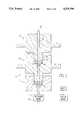
- FIG. 1is a schematic representation showing a first embodiment of the variable restrictor.
- FIG. 2is a schematic representation showing the compression structure.
- FIG. 3is a schematic representation showing a second embodiment of the variable restrictor.
- FIGS. 4a and 4bare schematic representations showing a preferred embodiment of the variable restrictor.
- FIG. 5is a block diagram of the variable restrictor.
- FIG. 6is a schematic representation showing an alternative embodiment of the variable restrictor.
- FIG. 1there is shown an apparatus 10 for restricting supercritical fluid.
- the apparatus 10comprises an elastic tube 12 through which the supercritical fluid flows.
- the compressing meansis in separable and releasable contact with the tube so the tube can be removed from the compressing means and replaced without damage to the compressing means.
- the supercritical fluidis at a pressure of at least 100 atm on one side of the compressing means.
- the facilitating meansis in communication with the tube in proximity to the compressing means.
- the adjustable compressing means 14includes a first member 16 having a first opening 18 through which the tube 12 extends.
- the first opening 18preferably has a threaded portion 20.
- the second member 22preferably has a threaded shaft 26 for threadingly engaging with the threaded portion 20 of the first opening 18.
- a compression structure 28is seated within the first opening 18 in contact with the elastic tube 12 such that as the threaded shaft 26 is screwed within the threaded portion 18, the compression structure 28 adjustably compresses the tube 12.
- the first opening 18has a tapered portion 30 upon which a tapered compression member 32 of the compression structure 28 is seated. As shown in FIG.
- the compression structure 28can have a spacer 34 for use when commercially available parts do not provide sufficient thread length.
- the spacer 34can be used to fill the space 35 as the compression structure 28 compresses the tube 12.
- the adjustable compressing means 14can also be a pneumatically or hydraulically controlled clamp, such as a pneumatic drill chuck.
- the adjustable compressing means 14includes a body member 70 having a first hole 72 through which the tube 12 extends and a threaded hole 74, in communication with and essentially perpendicular to the first hole, through which a threaded compression shaft 76 extends.
- the threaded shaft 76can adjustably compress a ball bearing 78 into the tube 12.
- the threaded shaftcan have a shaped end for compressing the tube 12.
- a flow sensor or pressure sensoris provided for determining the level of supercritical fluid restriction.
- the flow sensoris preferably in communication with a motor through control means so that the apparatus 10 can automatically adjust itself corresponding to the supercritical fluid flow.
- the elasticity of the tube 12allows it to expand when the compression means 14 is loosened.
- a tubecomprised of poly ether ether ketone (PEEK), as well as PTFE or stainless steel, to name but a few of the possible elastic materials, exhibits the necessary properties of elasticity and durability. It should be noted that in very high pressure applications, PEEK tubing works best. With respect to PEEK, a torque of at least 60 in.-lbs. thereon will cause the PEEK tube to experience compression.
- PEEKpoly ether ether ketone
- the apparatus 10can be self-adjusting.
- the determining means 36can operate by sensing pressure with a pressure sensor upstream of the restrictor and then controlling the compression on the restrictor to adjust the upstream pressure or by sensing flow with a flow sensor either upstream of the restrictor or downstream of the restrictor and then adjusting the restrictor to a set flow rate.
- the pressure sensorcan be a transducer disposed in the dead leg of a "T" positioned upstream of the restrictor. If a flow sensor is utilized, then on the inlet side of the restrictor, a liquid flow sensor such as a Brooks in-line flow sensor can be utilized; or, on the outlet side, a gas flow meter can be used.
- the determining meansgenerates a signal corresponding to the flow, the pressure or both in the tube 12.
- a motoris provided for automatically adjusting the compressing means according to the signal.
- the motorcan be a worm gear that turns the first member 16 within the second member 22.
- the facilitating meansincludes heating means such as a heating coil which is positioned adjacent to the first member 16 in any preferred manner such that heat produced by the heating coil heats the tube 12 and the fluid within. Heating the tube 12 in proximity to the restrictor reduces clogging in the tube 12.
- the facilitating meanscan include means for producing vibrations, means for producing microwaves or, means for producing ultrasound, separately or in combination with heat.
- microwavescan be used to heat the tubing 12.
- the facilitating meansintroduces energy to the supercritical fluid in the tube 12 in proximity to the restrictor to prevent clogging thereof.
- the microwave producing means and the ultrasound producing meansare positioned adjacent to the tube 12 in any desired manner such that their respective produced energy interacts with the fluid in tube 12 to reduce clogging.
- the vibration producing meanscan be positioned in contact with the first member 16 such that the first member 16 is vibrated which in turn vibrates the tube 24 and the fluid within.
- the third member 42has a third opening 44 through which the tube 12 extends for compressing a second portion 46 of the tube 12.
- the third member 42has a second threaded shaft 48 for engaging with a second threaded portion 50 of a second opening 52 disposed within the second member 16.
- the second shaft 48is forced against a second compression structure 54 disposed within the second opening 52, compressing the second portion 46 of the elastic tube 12.
- the second compression structure 54is used as a clamp to hold the tube 12 while the first compression structure 32 is used as an adjustable supercritical fluid restrictor. In this way, the second compression structure 54 should not become loose, allowing the tube 12 to come out of the first member 16 due to the high pressures present during operation. Loosening or tightening should only occur with respect to the first compression structure 32 to provide the desired adjustment of the flow in the tube 12.
- the present inventionis also a method of restricting supercritical fluid flow.
- the methodcomprises the steps of establishing supercritical fluid flow through an elastic tube and adjustably compressing the elastic tube such that a desired flow rate is maintained therein.
- the applying energy stepincludes the step of heating the supercritical fluid within the tube in proximity to the compression means.
- the compression stepincludes the steps of screwing a threaded shaft within a threaded opening such that a compression member adjustably compresses the elastic tube.
- the screwing stepcan include the steps of screwing the threaded shaft into the threaded opening such that the tube is compressed a first amount and unscrewing the threaded from the threaded opening. Then, there are the steps of placing a spacer in contact with the compression member and screwing the threaded shaft into the threaded opening such that the compression member compresses the elastic tube a second amount. In this manner, a threaded shaft having insufficient thread length to fully compress its compression member can be essentially lengthened by the addition of a spacer to compress the compression member to the desired degree.
- an elastic tube 12comprised of PEEK is inserted into the compressing means 14.
- the tube 12has an outside diameter of 1/16 of an inch and a length of 6 cm.
- the channel 60 within the tube 12originally has a uniform diameter of 0.007 inches.
- the PEEK tubingis coupled to input and output tubes with 1/16 valve fittings (not shown).
- the first member 16is a Valco 1/6 nut CAT #ZN1.
- the second member 22is a Valco internal reducer 1/8 ⁇ 1/16 CAT #12R21 which comes with a stainless steel ferrule seat 23. During compression, space 35 will be filled by the deformed ferrule seat 23.
- the third member 42is a Valco 1/8 ⁇ 1/16 bulkhead reducing union CAT #2BRUZ.5T.
- the second compression member 54is an Alltech ferrule 1/8 ⁇ 1/16 CAT #RF-200/100-V(j31) and is essentially used to clamp the PEEK tube 22. Alternatively, the second compression member 54 can be a graphite/vespel ferrule.
- the first compression member 32is an Upchurch PEEK ferrule CAT #F-142 and is used to adjustably compress the PEEK tube 12 and is situated within the ferrule seat 23. Some of these parts are modified before they are used to insure proper fit and operation.
- the tube 12is then placed in fluidic connection with a source of CO 2 supercritical fluid and a heating coil disposed about the tube 12 is turned on.
- the supercritical fluidflows through the tube where the level of supercritical fluid restriction is monitored by flow sensor 38.
- the desired restrictionis entered into a computer which serves as the control means.
- the signals from the flow sensor 38communicate with the computer which compares the measured flow restriction with the desired flow restriction and controls the motor accordingly,
- the motormechanically turns the first member 16 such that the first compression structure 32 adjustably compresses against the first portion 47 of the elastic tube 12.
- the sensor 38, the control means and the motoract as a feedback control system which automatically control the compression of the first portion 47.
- Typical supercritical fluid restriction levelscause the pressure within the channel to drop from 100-680 atmospheres upstream of the restrictor 10 to a pressure of 1 atmosphere downstream of the restrictor 10 at a flow rate of 0.1 to 10 ml/min.
- the width of the channel necessary for this level of supercritical fluid restrictionis on the order of 0.01 mm.
Landscapes
- Engineering & Computer Science (AREA)
- General Engineering & Computer Science (AREA)
- Physics & Mathematics (AREA)
- General Physics & Mathematics (AREA)
- Mechanical Engineering (AREA)
- Extraction Or Liquid Replacement (AREA)
Abstract
Description
Claims (37)
Priority Applications (1)
| Application Number | Priority Date | Filing Date | Title |
|---|---|---|---|
| US07/848,424US5379790A (en) | 1992-01-31 | 1992-03-06 | Variable restriction |
Applications Claiming Priority (2)
| Application Number | Priority Date | Filing Date | Title |
|---|---|---|---|
| US07/828,729US5316262A (en) | 1992-01-31 | 1992-01-31 | Fluid restrictor apparatus and method for making the same |
| US07/848,424US5379790A (en) | 1992-01-31 | 1992-03-06 | Variable restriction |
Related Parent Applications (1)
| Application Number | Title | Priority Date | Filing Date |
|---|---|---|---|
| US07/828,729Continuation-In-PartUS5316262A (en) | 1992-01-31 | 1992-01-31 | Fluid restrictor apparatus and method for making the same |
Publications (1)
| Publication Number | Publication Date |
|---|---|
| US5379790Atrue US5379790A (en) | 1995-01-10 |
Family
ID=46247696
Family Applications (1)
| Application Number | Title | Priority Date | Filing Date |
|---|---|---|---|
| US07/848,424Expired - Fee RelatedUS5379790A (en) | 1992-01-31 | 1992-03-06 | Variable restriction |
Country Status (1)
| Country | Link |
|---|---|
| US (1) | US5379790A (en) |
Cited By (13)
| Publication number | Priority date | Publication date | Assignee | Title |
|---|---|---|---|---|
| US5911881A (en)* | 1990-07-13 | 1999-06-15 | Isco, Inc. | Apparatus and method for collecting analyte in supercritical fluid extraction |
| US6071408A (en)* | 1990-07-13 | 2000-06-06 | Isco, Inc. | Apparatus and method for supercritical fluid extraction |
| US6083399A (en)* | 1990-07-13 | 2000-07-04 | Isco, Inc. | Apparatus and method for supercritical fluid extraction |
| US6149814A (en)* | 1990-07-13 | 2000-11-21 | Isco, Inc. | Apparatus and method for supercritical fluid extraction or supercritical fluid chromatography |
| US6296769B1 (en) | 1990-07-13 | 2001-10-02 | Isco, Inc. | Multi-chambered supercritical fluid extraction cartridge and processes using it |
| WO2003085297A1 (en)* | 2002-04-01 | 2003-10-16 | Emerson Electric Co. | Pinch valve with pressure containing member |
| US20040089827A1 (en)* | 2000-07-11 | 2004-05-13 | Arno Drechsel | Valve |
| US20040112436A1 (en)* | 2002-04-01 | 2004-06-17 | Emerson Electric Co. | Pinch valve |
| US20050012327A1 (en)* | 2001-10-19 | 2005-01-20 | Owe Salven | Connector |
| US20050102691A1 (en)* | 2003-11-11 | 2005-05-12 | Hsien-Tsung Chiu | Optical disk drive |
| US20100072748A1 (en)* | 2006-08-12 | 2010-03-25 | Van Pelt Colleen K | Compression connection |
| US20150129614A1 (en)* | 2013-03-15 | 2015-05-14 | The Coca-Cola Company | Beverage Dispenser Nozzle |
| GB2571565A (en)* | 2018-03-01 | 2019-09-04 | Thermo Fisher Scient Bremen Gmbh | Inert non-adsorbing crimpable capillaries and device for adjusting gas flow in isotope ratio analysis |
Citations (15)
| Publication number | Priority date | Publication date | Assignee | Title |
|---|---|---|---|---|
| US1657663A (en)* | 1926-01-08 | 1928-01-31 | Francis C Devereux | Valve |
| US2532452A (en)* | 1945-06-14 | 1950-12-05 | Albert Wittlin | Externally adjustable tubular fluid flow restrictor for refrigeration systems |
| US2946341A (en)* | 1957-02-21 | 1960-07-26 | Sullivan Valve & Engineering Co | Unidirectional check valve |
| US3095175A (en)* | 1961-01-19 | 1963-06-25 | Iketani Taisho | Gaseous fuel regulating device for liquefied gas lighters |
| US3180350A (en)* | 1962-04-20 | 1965-04-27 | Gen Motors Corp | Mixing apparatus |
| US3429549A (en)* | 1966-11-22 | 1969-02-25 | Davol Rubber Co | Metering device for flexible tubes |
| US3685786A (en)* | 1970-08-31 | 1972-08-22 | Riley D Woodson | Elastic valve element having variable orifice |
| US4205819A (en)* | 1978-06-19 | 1980-06-03 | Emil Soika | Flow clamp device |
| US4394873A (en)* | 1980-04-28 | 1983-07-26 | Ryco Graphic Manufacturing, Inc. | Fluid valve with compressible channel |
| US4512545A (en)* | 1982-06-24 | 1985-04-23 | Dionex Corporation | Externally actuated valve assembly and method |
| US4687176A (en)* | 1986-07-07 | 1987-08-18 | Olsen C Eric | Flow control valve for a flexible walled tube |
| US4776618A (en)* | 1987-08-14 | 1988-10-11 | Marathon Oil Company | High pressure coupling |
| US4811928A (en)* | 1985-12-04 | 1989-03-14 | Pfrimmer-Viggo Gmbh & Co. Kg | Control clamp for infusion hoses |
| EP0384969A2 (en)* | 1989-02-27 | 1990-09-05 | Hewlett-Packard Company | Axially-driven valve controlled trapping assembly |
| US5013006A (en)* | 1989-07-24 | 1991-05-07 | Cosmo Instruments Co., Ltd. | Micro-leakage regulating valve |
- 1992
- 1992-03-06USUS07/848,424patent/US5379790A/ennot_activeExpired - Fee Related
Patent Citations (15)
| Publication number | Priority date | Publication date | Assignee | Title |
|---|---|---|---|---|
| US1657663A (en)* | 1926-01-08 | 1928-01-31 | Francis C Devereux | Valve |
| US2532452A (en)* | 1945-06-14 | 1950-12-05 | Albert Wittlin | Externally adjustable tubular fluid flow restrictor for refrigeration systems |
| US2946341A (en)* | 1957-02-21 | 1960-07-26 | Sullivan Valve & Engineering Co | Unidirectional check valve |
| US3095175A (en)* | 1961-01-19 | 1963-06-25 | Iketani Taisho | Gaseous fuel regulating device for liquefied gas lighters |
| US3180350A (en)* | 1962-04-20 | 1965-04-27 | Gen Motors Corp | Mixing apparatus |
| US3429549A (en)* | 1966-11-22 | 1969-02-25 | Davol Rubber Co | Metering device for flexible tubes |
| US3685786A (en)* | 1970-08-31 | 1972-08-22 | Riley D Woodson | Elastic valve element having variable orifice |
| US4205819A (en)* | 1978-06-19 | 1980-06-03 | Emil Soika | Flow clamp device |
| US4394873A (en)* | 1980-04-28 | 1983-07-26 | Ryco Graphic Manufacturing, Inc. | Fluid valve with compressible channel |
| US4512545A (en)* | 1982-06-24 | 1985-04-23 | Dionex Corporation | Externally actuated valve assembly and method |
| US4811928A (en)* | 1985-12-04 | 1989-03-14 | Pfrimmer-Viggo Gmbh & Co. Kg | Control clamp for infusion hoses |
| US4687176A (en)* | 1986-07-07 | 1987-08-18 | Olsen C Eric | Flow control valve for a flexible walled tube |
| US4776618A (en)* | 1987-08-14 | 1988-10-11 | Marathon Oil Company | High pressure coupling |
| EP0384969A2 (en)* | 1989-02-27 | 1990-09-05 | Hewlett-Packard Company | Axially-driven valve controlled trapping assembly |
| US5013006A (en)* | 1989-07-24 | 1991-05-07 | Cosmo Instruments Co., Ltd. | Micro-leakage regulating valve |
Non-Patent Citations (2)
| Title |
|---|
| "Analytical-Scale Supercritical Fluid Extraction" by Steven Hawthorne, Analytical Chemistry, vol. 62, No. 11, Jun. 1, 1990. |
| Analytical Scale Supercritical Fluid Extraction by Steven Hawthorne, Analytical Chemistry, vol. 62, No. 11, Jun. 1, 1990.* |
Cited By (34)
| Publication number | Priority date | Publication date | Assignee | Title |
|---|---|---|---|---|
| US6296769B1 (en) | 1990-07-13 | 2001-10-02 | Isco, Inc. | Multi-chambered supercritical fluid extraction cartridge and processes using it |
| US6319410B1 (en) | 1990-07-13 | 2001-11-20 | Isco, Inc. | Apparatus and method for super critical fluid extraction |
| US6083399A (en)* | 1990-07-13 | 2000-07-04 | Isco, Inc. | Apparatus and method for supercritical fluid extraction |
| US6149814A (en)* | 1990-07-13 | 2000-11-21 | Isco, Inc. | Apparatus and method for supercritical fluid extraction or supercritical fluid chromatography |
| US6241890B1 (en) | 1990-07-13 | 2001-06-05 | Isco, Inc. | Apparatus and method for supercritical fluid extraction |
| US6294088B1 (en) | 1990-07-13 | 2001-09-25 | Isco, Inc. | Apparatus and method for supercritical fluid extraction or supercritical fluid chromatography |
| US5911881A (en)* | 1990-07-13 | 1999-06-15 | Isco, Inc. | Apparatus and method for collecting analyte in supercritical fluid extraction |
| US6071408A (en)* | 1990-07-13 | 2000-06-06 | Isco, Inc. | Apparatus and method for supercritical fluid extraction |
| US6892900B2 (en) | 2000-07-11 | 2005-05-17 | Arno Drechsel | Valve |
| US20040089827A1 (en)* | 2000-07-11 | 2004-05-13 | Arno Drechsel | Valve |
| US20080054630A1 (en)* | 2001-10-19 | 2008-03-06 | Ge Healthcare Bio-Sciences Ab | Connector |
| US20050012327A1 (en)* | 2001-10-19 | 2005-01-20 | Owe Salven | Connector |
| US7472928B2 (en) | 2001-10-19 | 2009-01-06 | Ge Healthcare Bio-Sciences Ab | Connector |
| US7338088B2 (en)* | 2001-10-19 | 2008-03-04 | Ge Healthcare Bio-Sciences Ab | Connector |
| WO2003085297A1 (en)* | 2002-04-01 | 2003-10-16 | Emerson Electric Co. | Pinch valve with pressure containing member |
| US20040112436A1 (en)* | 2002-04-01 | 2004-06-17 | Emerson Electric Co. | Pinch valve |
| US7104275B2 (en) | 2002-04-01 | 2006-09-12 | Emerson Electric Co. | Pinch valve |
| WO2005031198A1 (en)* | 2003-09-26 | 2005-04-07 | Emerson Electric Co. | Pinch valve |
| RU2327074C2 (en)* | 2003-09-26 | 2008-06-20 | Эмерсон Электрик Ко. | Control valve, device to measure and control flow |
| CN100398885C (en)* | 2003-09-26 | 2008-07-02 | 艾默生电气公司 | Pinch valve |
| US20050102691A1 (en)* | 2003-11-11 | 2005-05-12 | Hsien-Tsung Chiu | Optical disk drive |
| US10077859B2 (en) | 2006-08-12 | 2018-09-18 | Corsolutions Llc | Compression connection |
| US20100072748A1 (en)* | 2006-08-12 | 2010-03-25 | Van Pelt Colleen K | Compression connection |
| US8851528B2 (en)* | 2006-08-12 | 2014-10-07 | Corsolutions Llc | Compression connection |
| US20150129614A1 (en)* | 2013-03-15 | 2015-05-14 | The Coca-Cola Company | Beverage Dispenser Nozzle |
| US9415991B2 (en)* | 2013-03-15 | 2016-08-16 | The Coca-Cola Company | Beverage dispenser nozzle |
| GB2571565A (en)* | 2018-03-01 | 2019-09-04 | Thermo Fisher Scient Bremen Gmbh | Inert non-adsorbing crimpable capillaries and device for adjusting gas flow in isotope ratio analysis |
| US20190272985A1 (en)* | 2018-03-01 | 2019-09-05 | Thermo Fisher Scientific (Bremen) Gmbh | Inert non-adsorbing crimpable capillaries and devices for adjusting gas flow in isotope ratio analysis |
| CN110223905A (en)* | 2018-03-01 | 2019-09-10 | 塞莫费雪科学(不来梅)有限公司 | Inert non-adsorbing crimpable capillary tube for isotope ratio analysis and device for regulating gas flow |
| GB2571565B (en)* | 2018-03-01 | 2021-05-26 | Thermo Fisher Scient Bremen Gmbh | Inert non-adsorbing crimpable capillaries and devices for adjusting gas flow in isotope ratio analysis |
| US11024496B2 (en)* | 2018-03-01 | 2021-06-01 | Thermo Fisher Scientific (Bremen) Gmbh | Inert non-adsorbing crimpable capillaries and devices for adjusting gas flow in isotope ratio analysis |
| US20210272788A1 (en)* | 2018-03-01 | 2021-09-02 | Thermo Fisher Scientific (Bremen) Gmbh | Inert non-adsorbing crimpable capillaries and devices for adjusting gas flow in isotope ratio analysis |
| CN110223905B (en)* | 2018-03-01 | 2022-06-07 | 塞莫费雪科学(不来梅)有限公司 | Inert non-adsorbent coilable capillaries and devices for regulating gas flow in isotope ratio analysis |
| US12159778B2 (en) | 2018-03-01 | 2024-12-03 | Thermo Fisher Scientific (Bremen) Gmbh | Inert non-adsorbing crimpable capillaries and devices for adjusting gas flow in isotope ratio analysis |
Similar Documents
| Publication | Publication Date | Title |
|---|---|---|
| US5379790A (en) | Variable restriction | |
| US5316262A (en) | Fluid restrictor apparatus and method for making the same | |
| US4187177A (en) | Column for high pressure liquid chromatography | |
| US20080105839A1 (en) | Flow control systems and control valves therefor | |
| EP0275933B1 (en) | Pressure control apparatus | |
| US5911954A (en) | Integral fitting and filter | |
| US4770212A (en) | Pressure compensated flow rate controllers | |
| US5197708A (en) | Tubing pinch valve device | |
| KR20020039268A (en) | Pinch Valve | |
| US6616434B1 (en) | Blowing agent metering system | |
| US5249929A (en) | Liquid chromatographic pump | |
| US2314767A (en) | Adjustable rubber valve | |
| US5339673A (en) | Gas chromatograph and method of using same | |
| JP4443057B2 (en) | Fluid pressure regulator with differential pressure setting control | |
| WO1995005229A1 (en) | Integral fitting and filter | |
| JP2005509823A (en) | Fluid flow controlled freeze / thaw valves for narrow bore capillaries or microfluidic devices | |
| US4917575A (en) | Liquid chromatographic pump | |
| US4719806A (en) | Fluid flow rate monitor probe | |
| EP1880202A1 (en) | System for controlling flow into chromatographic column using transfer line impedance | |
| JP3259655B2 (en) | Gas chromatograph analyzer | |
| RU2004119435A (en) | CORIOLIS MASS FLOW METER REGULATOR, PERFORMED FROM HIGH PURITY MATERIAL | |
| US2568123A (en) | Pressure reducing device for refrigerating apparatus | |
| JPH10512350A (en) | Integrated two-way flow control valve | |
| US5333648A (en) | Variable pressure reducing device | |
| US3840207A (en) | Flexible tube valve |
Legal Events
| Date | Code | Title | Description |
|---|---|---|---|
| AS | Assignment | Owner name:SUPREX CORPORATION, PENNSYLVANIA Free format text:ASSIGNMENT OF ASSIGNORS INTEREST.;ASSIGNOR:KOEBLER, DOUGLAS J.;REEL/FRAME:006058/0430 Effective date:19920305 | |
| AS | Assignment | Owner name:ENSECO, NEW JERSEY Free format text:ASSIGNMENT OF ASSIGNORS INTEREST.;ASSIGNOR:BRUCE, MARK L.;REEL/FRAME:006106/0471 Effective date:19920423 | |
| AS | Assignment | Owner name:EQUITAS, L.P., TENNESSEE Free format text:SECURITY INTEREST;ASSIGNOR:SUPREX CORPORATION;REEL/FRAME:007553/0258 Effective date:19950627 | |
| AS | Assignment | Owner name:SUPREX CORPORATION, PENNSYLVANIA Free format text:ASSIGNMENT OF ASSIGNORS INTEREST;ASSIGNOR:EQUITAS, L.P.;REEL/FRAME:008167/0920 Effective date:19960923 Owner name:ISCO, INC., NEBRASKA Free format text:ASSIGNMENT OF ASSIGNORS INTEREST;ASSIGNOR:SUPREX CORPORATION;REEL/FRAME:008167/0917 Effective date:19960913 | |
| FEPP | Fee payment procedure | Free format text:PAT HOLDER CLAIMS SMALL ENTITY STATUS - SMALL BUSINESS (ORIGINAL EVENT CODE: SM02); ENTITY STATUS OF PATENT OWNER: SMALL ENTITY | |
| FPAY | Fee payment | Year of fee payment:4 | |
| FPAY | Fee payment | Year of fee payment:8 | |
| REMI | Maintenance fee reminder mailed | ||
| FEPP | Fee payment procedure | Free format text:PAYOR NUMBER ASSIGNED (ORIGINAL EVENT CODE: ASPN); ENTITY STATUS OF PATENT OWNER: SMALL ENTITY | |
| AS | Assignment | Owner name:TELEDYNE ISCO, INC., NEBRASKA Free format text:CHANGE OF NAME;ASSIGNOR:ISCO, INC.;REEL/FRAME:016026/0251 Effective date:20040619 | |
| REMI | Maintenance fee reminder mailed | ||
| LAPS | Lapse for failure to pay maintenance fees | ||
| LAPS | Lapse for failure to pay maintenance fees | Free format text:PATENT EXPIRED FOR FAILURE TO PAY MAINTENANCE FEES (ORIGINAL EVENT CODE: EXP.); ENTITY STATUS OF PATENT OWNER: SMALL ENTITY | |
| STCH | Information on status: patent discontinuation | Free format text:PATENT EXPIRED DUE TO NONPAYMENT OF MAINTENANCE FEES UNDER 37 CFR 1.362 | |
| FP | Lapsed due to failure to pay maintenance fee | Effective date:20070110 |