US5379305A - Error correction system with selectable error correction capabilities - Google Patents
Error correction system with selectable error correction capabilitiesDownload PDFInfo
- Publication number
- US5379305A US5379305AUS07/918,208US91820892AUS5379305AUS 5379305 AUS5379305 AUS 5379305AUS 91820892 AUS91820892 AUS 91820892AUS 5379305 AUS5379305 AUS 5379305A
- Authority
- US
- United States
- Prior art keywords
- error
- symbols
- erasure
- code word
- error correction
- Prior art date
- Legal status (The legal status is an assumption and is not a legal conclusion. Google has not performed a legal analysis and makes no representation as to the accuracy of the status listed.)
- Expired - Lifetime
Links
Images


Classifications
- G—PHYSICS
- G06—COMPUTING OR CALCULATING; COUNTING
- G06F—ELECTRIC DIGITAL DATA PROCESSING
- G06F11/00—Error detection; Error correction; Monitoring
- H—ELECTRICITY
- H03—ELECTRONIC CIRCUITRY
- H03M—CODING; DECODING; CODE CONVERSION IN GENERAL
- H03M13/00—Coding, decoding or code conversion, for error detection or error correction; Coding theory basic assumptions; Coding bounds; Error probability evaluation methods; Channel models; Simulation or testing of codes
- H03M13/35—Unequal or adaptive error protection, e.g. by providing a different level of protection according to significance of source information or by adapting the coding according to the change of transmission channel characteristics
Definitions
- the inventionrelates generally to error correction of data and more particularly to error correction encoding with selectable error correction capabilities.
- ECCerror correction codes
- ECCError Correcting Codes
- redundancy symbolsare then appended to the data string to form code words--data symbols plus redundancy symbols--and the code words are then stored on the disk.
- code words containing the data symbolsare retrieved from the disk and mathematically decoded.
- any errors in the dataare detected and, if possible, corrected through manipulation of the redundancy symbols [For a detailed description of decoding see Peterson and Weldon, Error Correcting Codes, 2d Edition, MIT Press, 1972].
- Stored digital code wordscan contain multiple errors.
- One of the most effective types of ECC used for the correction of multiple errorsis a Reed-Solomon code see Peterson and Weldon, Error Correcting Codes]. Error detection and correction techniques for Reed-Solomon ECC's are well known. Id.
- An (n,k) Reed-Solomon ECCencodes k data symbols to form n-k, or r, redundancy symbols.
- the number of errors which an ECC can correctis directly related to the number of redundancy symbols it produces.
- Each redundancy symbolcan be used to determine, that is, solve for, either an error location or an error value. Thus, two redundancy symbols are required to correct each error.
- the (n,k) codecan correct up to (D-1)/2 errors in an n-symbol code word.
- An erasureis an error with a known location. Such errors may, for example, be detected during detection and demodulation of signals retrieved from a magnetic disk drive.
- the systemretains a pointer to the location of the erasure. Accordingly, only one redundancy symbol is required to correct an erasure since only the data value of the erasure is unknown.
- the (n,k) codecan thus correct e erasures, 0 ⁇ e ⁇ D-1, and [(D-1)-e]/2 errors.
- a system designermay not be able to find a Reed-Solomon ECC which can correct a desired number of errors in the k data symbols, that is, a code which generates R redundancy symbols by encoding k data symbols.
- the designermay, for example, find a code which generates R+t redundancy symbols by encoding the k data symbols and formulates code words with k+R+t symbols.
- Such a codeis not acceptable, however, for a system which has allocated to a code word a (k+R)-symbol storage space.
- the designermay select an ECC with a longer length, for example, an (N,K) code, where N>n and K>k, which produces N-K, or R, redundancy symbols and then truncate the code word by eliminating some of the data symbols.
- N,Kan (N,K) code
- N>n and K>kwhich produces N-K, or R
- redundancy symbolsand then truncate the code word by eliminating some of the data symbols.
- This processis often termed "shortening" of the code, however, we shall use the term truncate to avoid confusion with the system described herein.
- the systemcould replace the truncated symbols and employ conventional error correction techniques designed for the (N,K) code.
- the systemthus manipulates the R redundancy symbols to generate error syndromes and determines from these the error locations and error values.
- the systemcan generate the error syndrome without replacing the truncated symbols.
- the systemdetermines error location using these syndromes, the system must take into account the truncated maximum code word length, which is N-i symbols. Using either approach, the system manipulates the R redundancy symbols to correct up to R/2 code word errors in the N-i code word symbols.
- a known data processing systemrequires, for certain applications, the capability to correct a large number of errors in the data, the system must use a powerful ECC which produces a large number of redundancy symbols for a given number of data symbols. If the system can sometimes, or for certain applications, operate with a reduced error correction capability it can use a less powerful ECC which produces fewer redundancy symbols for the same amount of data. The system can thus allocate a larger or smaller amount of storage space to a given code word, depending on the error correction requirements.
- the systemmay use fewer redundancy symbols, that is, a less powerful ECC, to protect the data then it uses to protect data stored on an older, potentially deteriorating disk.
- the systemmay, in essence, rate the disks according to their overall integrity, or associated error rates, and use more or less powerful ECCs to protect the data stored on the disks, depending on their rankings.
- the systemmay use a more or less powerful code depending on the type of storage medium used, also.
- a system which has a capability of storing data on both optical and magnetic disksmay use a more powerful code for data which it is storing on the optical disks.
- the quality of the optical disksis generally not as good as the quality of magnetic disks, and thus, the probability of having a defect in the optical disk is higher, also, and the probability of that defect effecting a relatively large number of data symbols is also higher than the probabilities associated with magnetic disks. Accordingly, the system protects the data with an ECC which can correct a greater number of errors.
- data which is to be sent a long distancemay be protected with more redundancy symbols then data which is to be sent a shorter distance.
- the systemthus protects the data from transmission errors which are more likely to occur when data is transmitted over the longer communications paths.
- An error correction systemwhich uses a single encoder with selectable levels of redundancy to encode and decode data, produces for the same number of data symbols code words with selectable numbers of redundancy symbols.
- the encoderencodes k data symbols in accordance with an (n,k) Reed-Solomon ECC to generate r redundancy symbols.
- the systemselects a desired level of error correction from 1 error to r/2 errors per code word based on, for example, the medium on which the data is to be stored.
- the systemthen arbitrarily deletes p of the generated redundancy symbols to produce an (n-p)-symbol code word containing k data symbols and r-p redundancy symbols where (r-p)/2 corresponds to the selected level of error protection.
- This code wordis part of an (n-p,k) punctured code, which is less powerful than the (n,k) code.
- the systemtreats the p deleted symbols as erasures and corrects the p erasures and up to (r-p)/2 errors in the code word.
- the systemfirst fills-in the p deleted symbols with pre-assigned symbols, for example, all zero symbols, and establishes pointers to these p symbols, as well as e pointers to detected erasure locations.
- the systemmanipulates the r-p redundancy symbols and the p pre-assigned symbols to produce error syndromes.
- the systemdetermines the error locations and error values for the detected errors and the error values for the e detected erasures, as well as the error values for the p pre-assigned symbols.
- the systemdeletes the last p of the redundancy symbols.
- the systemtakes advantage of the cyclic property of the Reed-Solomon code and decodes the (n-p)-symbol code word as if the p deleted redundancy symbols are taking the place of pleading code word symbols which are deleted in shortening the code word.
- the systemthus saves time by avoiding filling-in the p deleted redundancy symbols with the pre-assigned symbols during decoding.
- the systemmodifies the error syndromes generated for this (n-p)-symbol code word so that the error locations and error values calculated using these syndromes correspond with the code word symbols, which are essentially shifted p symbol-locations, as discussed in detail below.
- the systemdecodes the (n-p)-symbol code word and generates error syndromes, without filling-in the p deleted symbols. It then modifies the error syndromes to correspond with the locations of these n-p symbols in the N symbol code word, which are cyclically shifted p symbol locations. This system is discussed in detail below.
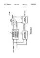
- FIG. 1depicts, in block diagram form, a data processing system
- FIG. 2is a block diagram of an encoding system of FIG. 1;
- FIG. 3a block diagram of an error correction system
- FIG. 4is a flow chart of the operations of the error correction system depicted in FIG. 3;
- FIG. 5is a block diagram of a preferred embodiment of an error correction system
- FIG. 6is a flow chart of the operations of one embodiment of a syndrome calculator depicted in FIG. 5 that iteratively modifies error syndromes;
- FIG. 7is a flow chart of the operations of one embodiment of an error corrector depicted in FIG. 5 that iteratively modifies error and erasure values;
- FIG. 8is a flow chart of the operations of another embodiment of the syndrome calculator depicted in FIG. 5 that modifies error syndromes in parallel;
- FIG. 9is a flow chart of the operations of another embodiment of the error corrector depicted in FIG. 5 that modifies error and erasure values in parallel.
- FIG. 1depicts a data processing system 2 which encodes data for storage on optical storage devices 6, magnetic storage devices 7 or for further transmission to a network node 8.
- a system controller 4provides to an encoding system 10 data and control information.
- the encoding/decoding system 10encodes the data in accordance with an error correction code (ECC) and generates redundancy symbols. It then selects a number of the generated redundancy symbols and appends them to the data to produce error correction code words, as discussed in more detail with reference to FIG. 2 below.
- ECCerror correction code
- the number of redundancy symbols selectedmay vary depending on the destination of the data, for example, the device on which the data are to be stored.
- the encoding system 10under the control of the system controller, sends the code words for storage to a designated optical storage device 6 or magnetic storage device 7, or for further transmission to a network node 8.
- FIG. 2depicts the encoding portion of the encoding/decoding system 10 in more detail.
- the encoding system 10includes an encoder 12 for encoding data for error protection and a code word transmitter 16 for transmitting data code words to a designated storage or network device 6-8 (FIG. 1).
- the encoder 12encodes, in a conventional manner, k data symbols in accordance with an (n,k) Reed-Solomon code with generator polynomial g(x) and produces n-k, or r, redundancy symbols.
- the encoder 12temporarily retains the redundancy symbols in a buffer 14.
- the system controller 4selects a level of error correction based on, for example, the medium on which the data is to be stored.
- the controller 4sends to the encoder 12 a value p, 0 ⁇ p ⁇ r-2, associated with the selected level.
- the encoderthen deletes p of the r redundancy symbols and sends the remaining r-p symbols to code word transmitter 16.
- the transmitter 16appends the r-p redundancy symbols to the data symbols and transmits an (n-p)-symbol code word to a designated storage device 6 or 7 (FIG. 1 ).
- the data processing systemIf, for example, the data processing system is storing the data on a magnetic disk which has a relatively high error rate, it requires the full, (n-k)/2, error correction capabilities of the code.
- the encoderthen sends to the code word transmitter 16, in parallel or in a symbol-serial manner, all r of the redundancy symbols.
- the transmitter 16appends the r redundancy symbols to the k data symbols to form an n-symbol code word: ##STR1##
- the system controller 4sends to the encoder 12 a value p, where 0 ⁇ p ⁇ r-2.
- the encoder 12then arbitrarily deletes p symbols from the r redundancy symbols in buffer 14 and sends to the code word transmitter the remaining r-p redundancy symbols.
- the transmitter 16appends the r-p redundancy symbols to the k data symbols and produces an (n-p)-symbol code word: ##STR2## where c r-p-1 , . . . c 0 are the redundancy symbols forwarded by the encoder 12.
- the transmitter 16then sends the code word to the designated storage device.
- FIG. 3depicts an error correction system 20, which is included in the encoding/decoding system 10 of FIG. 1 and FIG. 4 is a flow chart describing the operations of the system 20, which detects and corrects errors in code words retrieved from, for example, a magnetic storage device 7.
- An erasure detector 22detects erasures in a retrieved (n-p)-symbol code word and retains in a buffer 24, for each detected erasure, a pointer to the associated code word symbol location (step 30).
- the detector 22also increments an erasure counter 23 for each detected erasure (step 32).
- the circuit detects e erasuresit increments the erasure counter 23 e-times and formulates and stores e pointers.
- the erasure detection circuitrythen appends p pointers, which correspond to the locations of the p deleted symbols, to these e pointers and increments the erasure counter 23 to a count of e+p (step 34).
- the compare circuit 25enables a syndrome calculator 26, which fills-in the p deleted redundancy symbols with predetermined symbols, for example, all-zero symbols, to produce an n-symbol code word (step 38).
- the syndrome calculator 26manipulates the n-symbol code word symbols using conventional techniques to produce code word error syndromes S j (step 40): ##EQU1## where c' k is the k th symbol of the received, or retrieved, n-symbol code word, Lr is the lowest root of the generator polynomial g(x) and multiplication and summation operations are Galois Field operations.
- the generated syndromesare checked to determine if they are all zeros, which indicates that there are no errors in the code word.
- the error correction system 20may omit this step if the code word is associated with p>0 erasures.
- the number of errors which can be corrected in a code word which has p deleted symbols, which are treated as p erasures,is (r-p)/2. If an additional "e" erasures are detected during decoding, a maximum of [(r-p)-e]/2 errors can be corrected along with the e+p erasures.
- the syndrome calculatornext selects a maximum number of errors, t, to be corrected, where 0 ⁇ t ⁇ [(D-1)-(e+p)]/2 (Step 42). The calculator selects t such that it takes advantage of the error correcting power of the code while, at the same time, it keeps to an acceptable value the probability that the error correction circuit will mistakenly "correct” non-erroneous code word symbols.
- the error correction circuitmay transform the received code word into another code word of the (n,k) code, which introduces into the data an undetectable decoding error.
- the error correction circuit 28receives the syndromes S j from the syndrome calculator 26 and the e+p erasure pointers from the erasure detection circuit 23 and corrects errors in the code word by performing, in a conventional manner, a t-error and (e+p)-erasure correction procedure (step 44). If the error correction circuit 28 can locate and correct all of the t+e detected errors and erasures, the error correction circuit sends the corrected code word data symbols to the device (not shown) which requested them. If the error correction circuit can not correct all of the errors, it labels the data symbols as erroneous and sends them along with the label to the requesting device.
- the decoding systemcan correct up to (r-p-e)/2 detected errors and e erasures in any code word formulated using r-p of the redundancy symbols generated by encoding the data in accordance with the original (n,k) ECC.
- the decoding systemneed not include separate decoders for code words containing various numbers of redundancy symbols. A single decoder can thus be used to decode code words associated with powerful error protection (r redundancy symbols) and code words associated with less powerful error protection (fewer than r redundancy symbols).
- the symbols that are deletedare the last p of the r redundancy symbols.
- the systemthus forms a code word by appending the first r-p redundancy symbols to the k data symbols.
- the systemcould decode the code word by appending p predetermined symbols to the end of a received code word to fill in the deleted symbols and correcting t errors and e+p erasures using conventional techniques, as discussed above.
- a preferred decoding techniquetakes advantage of the cyclic properties of Reed-Solomon codes and decodes the code word as if the p deleted redundancy symbols are taking the place of the p leading symbols which are ignored when shortening the code word.
- the code wordconceptually corresponds to: ##STR3##
- the systemgenerates error syndromes using the (n-p)-symbol code word, and then modifies the syndromes to compensate for the p deleted symbols, as discussed in more detail below with reference to FIG. 5. Accordingly, the system avoids filling-in the p deleted symbols, and it can thus begin to calculate the error syndromes as soon as it receives the last code word symbol, c p .
- a decodermust, when it modifies the error syndromes to compensate for the p-symbol cyclic shifting, also take into account the previously deleted i leading code word symbols, depicted here as i all-zero symbols.
- the received code wordconceptually corresponds to: ##STR4## where the first non-zero data symbol, which is in location N-i in an N-symbol code word, is shifted to location (N-i)-p when the last p redundancy symbols are cyclically shifted to locations at the beginning of the N-symbol code word.
- a preferred embodiment of the error correcting systemmodifies the calculated syndromes based on the number of deletions, that is, based on the value p, such that these syndromes correspond to syndromes calculated for a code word of an (n-p,k) punctured code, as discussed in more detail below with reference to FIG. 5.
- the systemthen need only compute polynomials of degree t+e, instead of degree t+e+p, which saves in decoding time.
- the systemuses the modified syndromes and a t-error and e-erasure decoding procedure to determine t+e error values and t error locations for the (n-p)-symbol code word. Since the system earlier compensated for the p deleted redundancy symbols by modifying the syndromes, the system can now ignore these symbols. The system must, however, modify the t+e calculated error values, to conform them to the cyclically shifted code word, as discussed below with reference to FIGS. 6 through 9.
- FIG. 5depicts a system 50 for correcting errors in a code word using a t-error and e-erasure decoding procedure.
- the syndromescan be represented by a polynomial S(x),
- U(X)may be pre-calculated for various values of p and stored in the syndrome calculator or iteratively determined for each code word, as discussed below with reference to FIGS. 6 and 8.
- the error corrector circuit 54uses the remaining modified syndromes and the pointers to the e detected erasure locations to determine up to t error locations "ei" and t+e error values "ev.”
- FIGS. 6 and 8are flow charts which depict, respectively, the operations of the syndrome calculator 52 of FIG. 5 in modifying the syndromes S j iteratively and in modifying the syndromes in parallel.
- the calculatoragain increments the count c by 1 and compares it with p. If c ⁇ p, the calculator increments Lr by 1, decrements D by 1 and updates the syndromes (steps 60-62). The calculator repeats these operations until the count c exceeds p, which indicates that the modified syndromes correspond with a code word which has been punctured by the deletion of p symbols. The calculator then sends the modified syndromes to the error corrector circuit 54 (step 64).
- the error corrector circuit 54uses the modified syndromes to determine, in a conventional manner using a t-error and e-erasure error correction procedure, up to t error locations and t+e error values. The error corrector circuit must then manipulate the error values to compensate for the p-location cyclic shifting of the code word symbols. Accordingly, the error corrector circuit produces for each error value, ev, determined using the modified syndromes an actual error value, "av:"
- fU( ⁇ -ei )
- f( ⁇ n-1-ei +1)( ⁇ n-2-ei +1) . . . ( ⁇ n-P-ei +1), with the value N being used for n if the (n,k) code is a shortened version of the (N,K) code.
- the polynomial fmay be determined iteratively or in parallel.
- FIG. 7is a flow chart of the operations of the error correction circuit 54 in determining the polynomial iteratively.
- FIG. 9, discussed below,is a flow chart of the operations of the error correction circuit 54 in determining the polynomial in parallel.
- the error correction circuit 54initializes f to 1 and a count, c, to 0 (step 66).
- the correction circuitincrements the count by 1 (step 68), compares the count to p (Step 70) and if the count is less than or equal to p, the correction circuit multiplies f by ( ⁇ n-c-ei +1) and produces an updated f (step 72).
- the error correction circuitagain increments the count c by 1, compares it with p and if the count is less than or equal to p, it again multiplies f by ( ⁇ n-c-ei +1), and so forth.
- the correction circuitdivides ev by f to produce the associated actual error value, av, which corresponds to the symbol in location ei (step 74).
- the error correction circuitultimately combines the actual error value, av, with the code word symbol in location ei and corrects the symbol (step 76).
- the correction circuitmay correct each error as soon as the appropriate actual error value is determined, or it may store the actual error values and combine them with the corresponding code word symbols in one operation.
- FIG. 8depicts the operation of the syndrome calculator 52 (FIG. 5) which modifies the error syndromes S j in one step by pre-calculating U(x) and updating the syndromes to
- the syndrome calculatorincludes either a memory for storing the values for the coefficients of U(x) for all possible values of p, or a circuit which calculates the coefficients of U(X) for a selected value of p (step 78).
- the systemuses these modified syndromes to determine error locations, ei, and error values, ev, in a conventional manner.
- the systemmodifies them to correspond with the shifted code word. It thus either iteratively modifies the error values, as discussed with reference to FIG. 7 above, or it does so in parallel, as is depicted in FIG. 9
- the systemmodifies the error values in parallel, it uses the precalculated polynomial U(x) for the selected p and calculates for each detected error and erasure location, ei:
- the error correction circuit 54then corrects the error at location ei by combining the actual error value with the code word symbol, as discussed above with reference to FIG. 7.
- the error correction systemencodes and decodes data in accordance with a selectable number of redundancy symbols, which affords data selectable levels of error protection.
- the systemuses a single encoder to produce code words containing k data symbols, and a selected number of redundancy symbols between 2 and r symbols.
- the systemuses a single decoder to decode the variously sized code words and correct in each code word up to an appropriate number of errors, where the number of errors for each code word is related to the selected number of redundancy symbols.
- the systemdeletes the last p of the redundancy symbols, where r-p is the selected number of redundancy symbols for an (r-p)/2 desired error correction capability, and produces (n-p)-symbol code words of an (n-p,k) punctured code. It later decodes the code words as if the p deleted symbols are the symbols deleted in shortening the code word and produces error syndromes without filling-in the p deleted symbols. It then modifies the error syndromes appropriately to compensate for the p deleted symbols. Using these error syndromes, the system corrects up to t errors and e erasures using a t-error and e-erasure correction procedure to determine error locations and error and erasure values. It then modifies the error values to compensate for the p-symbol cyclic shifting of code word symbols attributable to the treatment of the deleted redundancy symbols as the p leading symbols which are deleted in the shortening of the code word.
Landscapes
- Engineering & Computer Science (AREA)
- Theoretical Computer Science (AREA)
- Physics & Mathematics (AREA)
- Probability & Statistics with Applications (AREA)
- Quality & Reliability (AREA)
- General Engineering & Computer Science (AREA)
- General Physics & Mathematics (AREA)
- Error Detection And Correction (AREA)
- Detection And Correction Of Errors (AREA)
Abstract
Description
S(x)-S.sub.Lr +S.sub.Lr+1 x+S.sub.Lr+2 x.sup.2 + . . . +S.sub.Lr+D-2 x.sup.D-2
U(x)=(α.sup.n-1 x+1)(α.sup.n-2 x+1) . . . (α.sup.n-p x+1),
TABLE 1 ______________________________________ position of unshifted position of shifted redundancy symbol symbol ______________________________________ 0 n - p 1 n -p + 1 2 n -p + 2 . . . -- h n - p + h . . . -- p - 1 n - p + (p - 1) = n - 1 ______________________________________
S'(x)=S(x)U(x).
U(x)=(α.sup.N-1 x+1)(α.sup.n-2 x+1) . . . (α.sup.N-P x+1).
S.sub.I =S.sub.I-1 α.sup.n-c +S.sub.I
I=Lr+(D-2) ,Lr+(D-2)-1, . . . , Lr
av=ev/f
S.sub.I =S.sub.I-P U.sub.P +S.sub.I-P+ 1 U.sub.P-1 + . . . +S.sub.I-1 U.sub.1 +S.sub.I
I=Lr+(D-2), . . . ,Lr+p.
F=U.sub.P α.sup.-eiP + . . . +U.sub.2 α.sup.-ei2 +U.sub.1 α.sup.-ei + 1
av=ev/f
Claims (15)
av=ev/f
S.sub.I =S.sub.I-1 α.sup.n-c +S.sub.I for I=Lr+(D-2),Lr+(D-2)-1, . . . ,Lr;
S.sub.I =S.sub.I-P U.sub.P +S.sub.I-P+1 U.sub.P-1 + . . . +S.sub.I-1 U.sub.1 +S.sub.I for I=Lr+(D-2), . . . , Lr+p.
f=U.sub.p α.sup.(-ei)(p) +U.sub.p-1 α.sup.(-ei)(p-1) + . . . +U.sub.1 α.sup.(-ei)(1) +1.
Priority Applications (7)
| Application Number | Priority Date | Filing Date | Title |
|---|---|---|---|
| US07/918,208US5379305A (en) | 1992-07-20 | 1992-07-20 | Error correction system with selectable error correction capabilities |
| JP5159357AJPH06188746A (en) | 1992-07-20 | 1993-06-29 | Error correction system |
| NL9301240ANL9301240A (en) | 1992-07-20 | 1993-07-15 | Error correction system with selectable error correction capabilities. |
| KR1019930013423AKR940006030A (en) | 1992-07-20 | 1993-07-16 | Error correction system which can select error correction selectively |
| GB9315033AGB2269034B (en) | 1992-07-20 | 1993-07-20 | Error correction system with selectable error correction capabilities |
| DE4324299ADE4324299A1 (en) | 1992-07-20 | 1993-07-20 | Error correction code system and method |
| TW082106430ATW257847B (en) | 1992-07-20 | 1993-08-11 |
Applications Claiming Priority (1)
| Application Number | Priority Date | Filing Date | Title |
|---|---|---|---|
| US07/918,208US5379305A (en) | 1992-07-20 | 1992-07-20 | Error correction system with selectable error correction capabilities |
Publications (1)
| Publication Number | Publication Date |
|---|---|
| US5379305Atrue US5379305A (en) | 1995-01-03 |
Family
ID=25439983
Family Applications (1)
| Application Number | Title | Priority Date | Filing Date |
|---|---|---|---|
| US07/918,208Expired - LifetimeUS5379305A (en) | 1992-07-20 | 1992-07-20 | Error correction system with selectable error correction capabilities |
Country Status (7)
| Country | Link |
|---|---|
| US (1) | US5379305A (en) |
| JP (1) | JPH06188746A (en) |
| KR (1) | KR940006030A (en) |
| DE (1) | DE4324299A1 (en) |
| GB (1) | GB2269034B (en) |
| NL (1) | NL9301240A (en) |
| TW (1) | TW257847B (en) |
Cited By (45)
| Publication number | Priority date | Publication date | Assignee | Title |
|---|---|---|---|---|
| US5465260A (en)* | 1993-11-04 | 1995-11-07 | Cirrus Logic, Inc. | Dual purpose cyclic redundancy check |
| US5481566A (en)* | 1993-12-29 | 1996-01-02 | At&T Corp. | Method and apparatus to increase efficiency of systematic codes |
| US5487077A (en)* | 1994-05-23 | 1996-01-23 | International Business Machines Corporation | Location dependent variable error correction processing for multi-track recording media using variable length coding means |
| US5539755A (en)* | 1992-05-19 | 1996-07-23 | U.S. Philips Corporation | Method and apparatus for decoding an error protected block of extended data |
| US5541939A (en)* | 1993-10-20 | 1996-07-30 | Goldstar Company, Ltd. | Error correction code decoder and a method thereof |
| US5574735A (en)* | 1993-11-29 | 1996-11-12 | Nippon Hoso Kyokai | Error correction circuit which substitutes bits into data stream during periods of data loss |
| US5579303A (en)* | 1994-09-28 | 1996-11-26 | Nec Corporation | Data transmission apparatus |
| US5600663A (en)* | 1994-11-16 | 1997-02-04 | Lucent Technologies Inc. | Adaptive forward error correction system |
| US5668976A (en)* | 1993-11-04 | 1997-09-16 | Cirrus Logic, Inc. | Error correction method and apparatus for disk drive emulator |
| US5768296A (en)* | 1994-07-01 | 1998-06-16 | Quantum Corporation | ECC system supporting different-length Reed-Solomon codes whose generator polynomials have common roots |
| US5781567A (en)* | 1994-10-24 | 1998-07-14 | Sony Corporation | Digital coding method and apparatus for the correction of burst errors |
| WO1998032231A1 (en)* | 1997-01-17 | 1998-07-23 | Qualcomm Incorporated | Method and apparatus for transmitting and receiving concatenated code data |
| US6003151A (en)* | 1997-02-04 | 1999-12-14 | Mediatek Inc. | Error correction and detection system for mass storage controller |
| US6038679A (en)* | 1994-11-30 | 2000-03-14 | International Business Machines Corporation | Adaptive data recovery method and apparatus |
| US6122766A (en)* | 1996-10-25 | 2000-09-19 | Matsushita Electric Industrial Co., Ltd. | Reed-Solomon decoder having a three-stage pipeline structure |
| WO2000057561A1 (en)* | 1999-03-23 | 2000-09-28 | Storage Technology Corporation | Pipelined high speed reed-solomon error/erasure decoder |
| US6327690B1 (en) | 1999-02-04 | 2001-12-04 | Intel Corporation | Integrated reed-solomon error correction code encoder and syndrome generator |
| US6405340B1 (en)* | 1999-07-02 | 2002-06-11 | Ericsson Inc. | Flexible method of error protection in communications systems |
| US6487692B1 (en)* | 1999-12-21 | 2002-11-26 | Lsi Logic Corporation | Reed-Solomon decoder |
| US20030095056A1 (en)* | 2001-08-20 | 2003-05-22 | Tolhuizen Ludovicus Marinus Gerardus Maria | Enhanced coding for informed decoders |
| EP1367727A1 (en)* | 2002-05-29 | 2003-12-03 | Siemens Aktiengesellschaft | Method and device for a communication system for finding roots of an error locator polynomial |
| US20030229841A1 (en)* | 2002-06-07 | 2003-12-11 | Alexander Kravtchenko | Reed-solomon decoder |
| US20040068689A1 (en)* | 2002-10-07 | 2004-04-08 | Rahul Saxena | Method and apparatus for CRC size reduction |
| US6732320B1 (en) | 2000-04-28 | 2004-05-04 | Promos Technologies Inc. | Method and system for improved error correction in optical media data processing |
| US6760361B2 (en)* | 1997-08-29 | 2004-07-06 | Telefonaktiebolaget Lm Ericsson (Publ) | Cell searching in a CDMA communications system |
| US6769088B1 (en)* | 1999-06-30 | 2004-07-27 | Maxtor Corporation | Sector-coding technique for reduced read-after-write operations |
| US20040246865A1 (en)* | 2002-01-25 | 2004-12-09 | Shoei Kobayashi | Information recording disc, recording and / or reproducing device and method |
| US20050044261A1 (en)* | 2003-07-18 | 2005-02-24 | Rahul Saxena | Method of operating a network switch |
| US20050166126A1 (en)* | 2002-05-08 | 2005-07-28 | Stefan Muller | Method of soft-decision decoding of reed-solomon codes |
| WO2005101207A1 (en)* | 2004-04-14 | 2005-10-27 | Koninklijke Philips Electronics N.V. | Data handling device that corrects errors in a data memory |
| US20050268205A1 (en)* | 2004-05-31 | 2005-12-01 | Samsung Electronics Co., Ltd. | Method and apparatus for decoding inner and outer codes in a mobile communication system |
| US6978415B1 (en) | 2001-11-27 | 2005-12-20 | Maxtor Corporation | Variable redundancy cyclic code encoders |
| US20070011591A1 (en)* | 2005-06-17 | 2007-01-11 | Li-Lien Lin | Method for generating syndrome value and apparatus thereof |
| US20080005384A1 (en)* | 2006-06-01 | 2008-01-03 | Broadcom Corporation, A California Corporation | Hard disk drive progressive channel interface |
| US20080046794A1 (en)* | 2002-01-25 | 2008-02-21 | Sony Corporation | Information recording device and method, information reproducing device and method, recording medium, program, and disc recording medium |
| US7532666B1 (en)* | 2004-05-18 | 2009-05-12 | Ikanos Communications Inc. | Method and apparatus for error correction in multi-line multi-tone gigabit transmission systems |
| US20100002669A1 (en)* | 2008-02-29 | 2010-01-07 | Sharp Laboratories Of America, Inc. | Systems and methods for adaptively selecting a decoding scheme to decode embedded information |
| US7681105B1 (en) | 2004-08-09 | 2010-03-16 | Bakbone Software, Inc. | Method for lock-free clustered erasure coding and recovery of data across a plurality of data stores in a network |
| US7681104B1 (en)* | 2004-08-09 | 2010-03-16 | Bakbone Software, Inc. | Method for erasure coding data across a plurality of data stores in a network |
| US20100218068A1 (en)* | 2009-02-23 | 2010-08-26 | International Business Machines Corporation | Multi-bit error correction method and apparatus based on a bch code and memory system |
| US20110107188A1 (en)* | 2009-10-29 | 2011-05-05 | Sandisk Il Ltd. | System and method of decoding data |
| US8868999B1 (en)* | 2011-01-06 | 2014-10-21 | Marvell International Ltd. | Systems and methods for erasure correction of iterative codes |
| US20150052370A1 (en)* | 2011-04-29 | 2015-02-19 | Seagate Technology Llc | Cascaded Data Encryption Dependent on Attributes of Physical Memory |
| CN115632666A (en)* | 2022-09-30 | 2023-01-20 | 电子科技大学 | A Novel Decoding Method of RS Codes with Correctable Deletion and Insertion Errors |
| US20230223961A1 (en)* | 2022-01-13 | 2023-07-13 | Micron Technology, Inc. | Iterative decoder for correcting dram device failures |
Families Citing this family (10)
| Publication number | Priority date | Publication date | Assignee | Title |
|---|---|---|---|---|
| JP2725598B2 (en)* | 1994-05-13 | 1998-03-11 | 日本電気株式会社 | Error correction encoder |
| TW311189B (en)* | 1996-09-30 | 1997-07-21 | United Microelectronics Corp | The error-corrected decoding method and its apparatus for Reed-Soloman code |
| US5838267A (en)* | 1996-10-09 | 1998-11-17 | Ericsson, Inc. | Method and apparatus for encoding and decoding digital information |
| GB2324390B (en)* | 1997-04-17 | 2002-05-29 | United Microelectronics Corp | Error decoding method and apparatus for Reed-Solomon codes |
| KR100452314B1 (en)* | 1997-08-20 | 2004-12-17 | 삼성전자주식회사 | Error correction code generation control circuit |
| US6148430A (en)* | 1998-05-15 | 2000-11-14 | Quantum Corporation | Encoding apparatus for RAID-6 system and tape drives |
| US6381726B1 (en)* | 1999-01-04 | 2002-04-30 | Maxtor Corporation | Architecture for soft decision decoding of linear block error correcting codes |
| US6463564B1 (en)* | 1999-09-14 | 2002-10-08 | Maxtor Corporation | Mis-synchronization detection system |
| JP2010034976A (en)* | 2008-07-30 | 2010-02-12 | Mitsubishi Electric Corp | Error-correction encoding apparatus, error-correction decoding apparatus, and error-correction encoding method |
| US8775868B2 (en)* | 2010-09-28 | 2014-07-08 | Pure Storage, Inc. | Adaptive RAID for an SSD environment |
Citations (13)
| Publication number | Priority date | Publication date | Assignee | Title |
|---|---|---|---|---|
| US4047151A (en)* | 1974-12-24 | 1977-09-06 | Rydbeck Nils R C | Adaptive error correcting transmission system |
| US4462101A (en)* | 1981-03-23 | 1984-07-24 | Kokusai Denshin Denwa Co., Ltd. | Maximum likelihood error correcting technique |
| US4506252A (en)* | 1981-05-05 | 1985-03-19 | Sperry Corporation | Ternary data encoding system |
| US4608692A (en)* | 1983-09-06 | 1986-08-26 | Kabushiki Kaisha Toshiba | Error correction circuit |
| US4654853A (en)* | 1983-09-26 | 1987-03-31 | Pioneer Electronic Corporation | Data transmission method |
| US4675869A (en)* | 1984-02-29 | 1987-06-23 | U.S. Philips Corporation | Fast decoder and encoder for Reed-Solomon codes and recording/playback apparatus having such an encoder/decoder |
| US4701923A (en)* | 1985-01-14 | 1987-10-20 | Oki Electric Industry Co., Ltd. | Adaptively coded data communication system with half duplex and/or full duplex function |
| US4835629A (en)* | 1986-10-02 | 1989-05-30 | Victor Company Of Japan, Ltd. | Code error correcting circuit |
| US4908621A (en)* | 1988-07-06 | 1990-03-13 | Tektronix, Inc. | Autocalibrated multistage A/D converter |
| US4918446A (en)* | 1987-09-30 | 1990-04-17 | Nec Corporation | Decoder with reduced synchronization capture time |
| US4922494A (en)* | 1987-05-20 | 1990-05-01 | Cselt (Centro Studi E Laboratori Telecomunicazioni S.P.A.) | Method of and circuit for decoding block-coded messages affected by symbol substitutions, insertions and deletions |
| US5224106A (en)* | 1990-05-09 | 1993-06-29 | Digital Equipment Corporation | Multi-level error correction system |
| US5267248A (en)* | 1990-12-24 | 1993-11-30 | Eastman Kodak Company | Method and apparatus for selecting an optimum error correction routine |
Family Cites Families (7)
| Publication number | Priority date | Publication date | Assignee | Title |
|---|---|---|---|---|
| JPH0778968B2 (en)* | 1986-02-14 | 1995-08-23 | 株式会社日立製作所 | Soft decision decoding method |
| US4785452A (en)* | 1986-04-25 | 1988-11-15 | International Business Machines Corporation | Error detection using variable field parity checking |
| JPS63237628A (en)* | 1987-03-26 | 1988-10-04 | Furukawa Electric Co Ltd:The | Coding method in vehicle multiplex transmission system |
| JPH03101536A (en)* | 1989-09-14 | 1991-04-26 | Fujitsu Ltd | Error correction coding and decoding system |
| JPH03172026A (en)* | 1989-11-30 | 1991-07-25 | Nec Corp | Encoding/decoding system |
| US5068858A (en)* | 1989-12-21 | 1991-11-26 | International Business Machines Corporation | Error correction capability varied with track location on a magnetic or optical disk |
| JPH04196725A (en)* | 1990-11-27 | 1992-07-16 | Matsushita Electric Ind Co Ltd | Variable length code encoding method |
- 1992
- 1992-07-20USUS07/918,208patent/US5379305A/ennot_activeExpired - Lifetime
- 1993
- 1993-06-29JPJP5159357Apatent/JPH06188746A/enactivePending
- 1993-07-15NLNL9301240Apatent/NL9301240A/ennot_activeApplication Discontinuation
- 1993-07-16KRKR1019930013423Apatent/KR940006030A/ennot_activeAbandoned
- 1993-07-20GBGB9315033Apatent/GB2269034B/ennot_activeExpired - Fee Related
- 1993-07-20DEDE4324299Apatent/DE4324299A1/ennot_activeWithdrawn
- 1993-08-11TWTW082106430Apatent/TW257847B/zhactive
Patent Citations (13)
| Publication number | Priority date | Publication date | Assignee | Title |
|---|---|---|---|---|
| US4047151A (en)* | 1974-12-24 | 1977-09-06 | Rydbeck Nils R C | Adaptive error correcting transmission system |
| US4462101A (en)* | 1981-03-23 | 1984-07-24 | Kokusai Denshin Denwa Co., Ltd. | Maximum likelihood error correcting technique |
| US4506252A (en)* | 1981-05-05 | 1985-03-19 | Sperry Corporation | Ternary data encoding system |
| US4608692A (en)* | 1983-09-06 | 1986-08-26 | Kabushiki Kaisha Toshiba | Error correction circuit |
| US4654853A (en)* | 1983-09-26 | 1987-03-31 | Pioneer Electronic Corporation | Data transmission method |
| US4675869A (en)* | 1984-02-29 | 1987-06-23 | U.S. Philips Corporation | Fast decoder and encoder for Reed-Solomon codes and recording/playback apparatus having such an encoder/decoder |
| US4701923A (en)* | 1985-01-14 | 1987-10-20 | Oki Electric Industry Co., Ltd. | Adaptively coded data communication system with half duplex and/or full duplex function |
| US4835629A (en)* | 1986-10-02 | 1989-05-30 | Victor Company Of Japan, Ltd. | Code error correcting circuit |
| US4922494A (en)* | 1987-05-20 | 1990-05-01 | Cselt (Centro Studi E Laboratori Telecomunicazioni S.P.A.) | Method of and circuit for decoding block-coded messages affected by symbol substitutions, insertions and deletions |
| US4918446A (en)* | 1987-09-30 | 1990-04-17 | Nec Corporation | Decoder with reduced synchronization capture time |
| US4908621A (en)* | 1988-07-06 | 1990-03-13 | Tektronix, Inc. | Autocalibrated multistage A/D converter |
| US5224106A (en)* | 1990-05-09 | 1993-06-29 | Digital Equipment Corporation | Multi-level error correction system |
| US5267248A (en)* | 1990-12-24 | 1993-11-30 | Eastman Kodak Company | Method and apparatus for selecting an optimum error correction routine |
Non-Patent Citations (6)
| Title |
|---|
| Bhargawa et al. "Error Control for Mobile Radio System" IEEE 1989 pp. 535-537. |
| Bhargawa et al. Error Control for Mobile Radio System IEEE 1989 pp. 535 537.* |
| Hussain et al. "Decoding a class of non binary codes using neural networks" IEEE 1991 pp. 41-43. |
| Hussain et al. Decoding a class of non binary codes using neural networks IEEE 1991 pp. 41 43.* |
| Soliman "Performance of Coded Systems Over Fading II is Persive Channels" IEEE 1992 pp. 51-59. |
| Soliman Performance of Coded Systems Over Fading II is Persive Channels IEEE 1992 pp. 51 59.* |
Cited By (77)
| Publication number | Priority date | Publication date | Assignee | Title |
|---|---|---|---|---|
| US5539755A (en)* | 1992-05-19 | 1996-07-23 | U.S. Philips Corporation | Method and apparatus for decoding an error protected block of extended data |
| US5541939A (en)* | 1993-10-20 | 1996-07-30 | Goldstar Company, Ltd. | Error correction code decoder and a method thereof |
| US5465260A (en)* | 1993-11-04 | 1995-11-07 | Cirrus Logic, Inc. | Dual purpose cyclic redundancy check |
| US5668976A (en)* | 1993-11-04 | 1997-09-16 | Cirrus Logic, Inc. | Error correction method and apparatus for disk drive emulator |
| US6018626A (en)* | 1993-11-04 | 2000-01-25 | Cirrus Logic, Inc. | Error correction method and apparatus for disk drive emulator |
| US5574735A (en)* | 1993-11-29 | 1996-11-12 | Nippon Hoso Kyokai | Error correction circuit which substitutes bits into data stream during periods of data loss |
| US5481566A (en)* | 1993-12-29 | 1996-01-02 | At&T Corp. | Method and apparatus to increase efficiency of systematic codes |
| US5487077A (en)* | 1994-05-23 | 1996-01-23 | International Business Machines Corporation | Location dependent variable error correction processing for multi-track recording media using variable length coding means |
| US5768296A (en)* | 1994-07-01 | 1998-06-16 | Quantum Corporation | ECC system supporting different-length Reed-Solomon codes whose generator polynomials have common roots |
| US5579303A (en)* | 1994-09-28 | 1996-11-26 | Nec Corporation | Data transmission apparatus |
| US5781567A (en)* | 1994-10-24 | 1998-07-14 | Sony Corporation | Digital coding method and apparatus for the correction of burst errors |
| US5600663A (en)* | 1994-11-16 | 1997-02-04 | Lucent Technologies Inc. | Adaptive forward error correction system |
| US6038679A (en)* | 1994-11-30 | 2000-03-14 | International Business Machines Corporation | Adaptive data recovery method and apparatus |
| US6122766A (en)* | 1996-10-25 | 2000-09-19 | Matsushita Electric Industrial Co., Ltd. | Reed-Solomon decoder having a three-stage pipeline structure |
| WO1998032231A1 (en)* | 1997-01-17 | 1998-07-23 | Qualcomm Incorporated | Method and apparatus for transmitting and receiving concatenated code data |
| US6003151A (en)* | 1997-02-04 | 1999-12-14 | Mediatek Inc. | Error correction and detection system for mass storage controller |
| US6760361B2 (en)* | 1997-08-29 | 2004-07-06 | Telefonaktiebolaget Lm Ericsson (Publ) | Cell searching in a CDMA communications system |
| US6327690B1 (en) | 1999-02-04 | 2001-12-04 | Intel Corporation | Integrated reed-solomon error correction code encoder and syndrome generator |
| WO2000057561A1 (en)* | 1999-03-23 | 2000-09-28 | Storage Technology Corporation | Pipelined high speed reed-solomon error/erasure decoder |
| US6347389B1 (en) | 1999-03-23 | 2002-02-12 | Storage Technology Corporation | Pipelined high speed reed-solomon error/erasure decoder |
| US6769088B1 (en)* | 1999-06-30 | 2004-07-27 | Maxtor Corporation | Sector-coding technique for reduced read-after-write operations |
| US6665834B2 (en)* | 1999-07-02 | 2003-12-16 | David R. Irvin | Flexible method of error protection in communications systems |
| US6405340B1 (en)* | 1999-07-02 | 2002-06-11 | Ericsson Inc. | Flexible method of error protection in communications systems |
| US6487692B1 (en)* | 1999-12-21 | 2002-11-26 | Lsi Logic Corporation | Reed-Solomon decoder |
| US6732320B1 (en) | 2000-04-28 | 2004-05-04 | Promos Technologies Inc. | Method and system for improved error correction in optical media data processing |
| US7047477B2 (en)* | 2001-08-20 | 2006-05-16 | Koninklijke Philips Electronics N.V. | Enhanced coding for informed decoders |
| US20030095056A1 (en)* | 2001-08-20 | 2003-05-22 | Tolhuizen Ludovicus Marinus Gerardus Maria | Enhanced coding for informed decoders |
| US6978415B1 (en) | 2001-11-27 | 2005-12-20 | Maxtor Corporation | Variable redundancy cyclic code encoders |
| US20070204202A1 (en)* | 2002-01-25 | 2007-08-30 | Sony Corporation | Information recording disc, recording and/or reproducing device and method |
| US7861142B2 (en)* | 2002-01-25 | 2010-12-28 | Sony Corporation | Information recording disc, recording and/or reproducing device and method |
| US7975206B2 (en)* | 2002-01-25 | 2011-07-05 | Sony Corporation | Information recording device and method, information reproducing device and method, recording medium, program, and disc recording medium |
| US20040246865A1 (en)* | 2002-01-25 | 2004-12-09 | Shoei Kobayashi | Information recording disc, recording and / or reproducing device and method |
| US7624331B2 (en) | 2002-01-25 | 2009-11-24 | Sony Corporation | Information recording disc, recording and/or reproducing device and method |
| US7454688B2 (en)* | 2002-01-25 | 2008-11-18 | Sony Corporation | Information recording disc, recording and/or reproducing device and method |
| US20080046794A1 (en)* | 2002-01-25 | 2008-02-21 | Sony Corporation | Information recording device and method, information reproducing device and method, recording medium, program, and disc recording medium |
| US20070198894A1 (en)* | 2002-01-25 | 2007-08-23 | Sony Corporation | Information recording disc, recording and/or reproducing device and method |
| US20050166126A1 (en)* | 2002-05-08 | 2005-07-28 | Stefan Muller | Method of soft-decision decoding of reed-solomon codes |
| US7353449B2 (en)* | 2002-05-08 | 2008-04-01 | Thomson Licensing | Method of soft-decision decoding of Reed-Solomon codes |
| EP1367727A1 (en)* | 2002-05-29 | 2003-12-03 | Siemens Aktiengesellschaft | Method and device for a communication system for finding roots of an error locator polynomial |
| US20030229841A1 (en)* | 2002-06-07 | 2003-12-11 | Alexander Kravtchenko | Reed-solomon decoder |
| US20040068689A1 (en)* | 2002-10-07 | 2004-04-08 | Rahul Saxena | Method and apparatus for CRC size reduction |
| US20050044261A1 (en)* | 2003-07-18 | 2005-02-24 | Rahul Saxena | Method of operating a network switch |
| US20070277083A1 (en)* | 2004-04-14 | 2007-11-29 | Koninklijke Philips Electronics, N.V. | Data Handling Device That Corects Errors In A Data Memory |
| WO2005101207A1 (en)* | 2004-04-14 | 2005-10-27 | Koninklijke Philips Electronics N.V. | Data handling device that corrects errors in a data memory |
| US7532666B1 (en)* | 2004-05-18 | 2009-05-12 | Ikanos Communications Inc. | Method and apparatus for error correction in multi-line multi-tone gigabit transmission systems |
| US20050268205A1 (en)* | 2004-05-31 | 2005-12-01 | Samsung Electronics Co., Ltd. | Method and apparatus for decoding inner and outer codes in a mobile communication system |
| US7539928B2 (en)* | 2004-05-31 | 2009-05-26 | Samsung Electronics Co., Ltd. | Method and apparatus for decoding inner and outer codes in a mobile communication system |
| US8051361B2 (en) | 2004-08-09 | 2011-11-01 | Quest Software, Inc. | Method for lock-free clustered erasure coding and recovery of data across a plurality of data stores in a network |
| US7681104B1 (en)* | 2004-08-09 | 2010-03-16 | Bakbone Software, Inc. | Method for erasure coding data across a plurality of data stores in a network |
| US20100162076A1 (en)* | 2004-08-09 | 2010-06-24 | Siew Yong Sim-Tang | Method for lock-free clustered erasure coding and recovery of data across a plurality of data stores in a network |
| US20100162044A1 (en)* | 2004-08-09 | 2010-06-24 | Siew Yong Sim-Tang | Method for erasure coding data across a plurality of data stores in a network |
| US7681105B1 (en) | 2004-08-09 | 2010-03-16 | Bakbone Software, Inc. | Method for lock-free clustered erasure coding and recovery of data across a plurality of data stores in a network |
| US9122627B1 (en) | 2004-08-09 | 2015-09-01 | Dell Software Inc. | Method for lock-free clustered erasure coding and recovery of data across a plurality of data stores in a network |
| US8086937B2 (en)* | 2004-08-09 | 2011-12-27 | Quest Software, Inc. | Method for erasure coding data across a plurality of data stores in a network |
| US8205139B1 (en) | 2004-08-09 | 2012-06-19 | Quest Software, Inc. | Method for lock-free clustered erasure coding and recovery of data across a plurality of data stores in a network |
| US20070011591A1 (en)* | 2005-06-17 | 2007-01-11 | Li-Lien Lin | Method for generating syndrome value and apparatus thereof |
| US20080005384A1 (en)* | 2006-06-01 | 2008-01-03 | Broadcom Corporation, A California Corporation | Hard disk drive progressive channel interface |
| US9083519B2 (en)* | 2008-02-29 | 2015-07-14 | Sharp Laboratories Of America, Inc. | Systems and methods for adaptively selecting a decoding scheme to decode embedded information |
| US20100002669A1 (en)* | 2008-02-29 | 2010-01-07 | Sharp Laboratories Of America, Inc. | Systems and methods for adaptively selecting a decoding scheme to decode embedded information |
| US9450615B2 (en)* | 2009-02-23 | 2016-09-20 | International Business Machines Corporation | Multi-bit error correction method and apparatus based on a BCH code and memory system |
| US20100218068A1 (en)* | 2009-02-23 | 2010-08-26 | International Business Machines Corporation | Multi-bit error correction method and apparatus based on a bch code and memory system |
| US8402352B2 (en)* | 2009-02-23 | 2013-03-19 | International Business Machines Corporation | Multi-bit error correction method and apparatus based on a BCH code and memory system |
| US10243589B2 (en)* | 2009-02-23 | 2019-03-26 | International Business Machines Corporation | Multi-bit error correction method and apparatus based on a BCH code and memory system |
| US9037953B2 (en)* | 2009-02-23 | 2015-05-19 | International Business Machines Corporation | Multi-bit error correction method and apparatus based on a BCH code and memory system |
| US20150222292A1 (en)* | 2009-02-23 | 2015-08-06 | International Business Machines Corporation | Multi-bit error correction method and apparatus based on a bch code and memory system |
| US20120311399A1 (en)* | 2009-02-23 | 2012-12-06 | International Business Machines Corporation | Multi-bit error correction method and apparatus based on a bch code and memory system |
| US8301987B2 (en) | 2009-10-29 | 2012-10-30 | Sandisk Il Ltd. | System and method of decoding data with reduced power consumption |
| US20110107188A1 (en)* | 2009-10-29 | 2011-05-05 | Sandisk Il Ltd. | System and method of decoding data |
| US8868999B1 (en)* | 2011-01-06 | 2014-10-21 | Marvell International Ltd. | Systems and methods for erasure correction of iterative codes |
| US9396136B2 (en)* | 2011-04-29 | 2016-07-19 | Seagate Technology Llc | Cascaded data encryption dependent on attributes of physical memory |
| US20150052370A1 (en)* | 2011-04-29 | 2015-02-19 | Seagate Technology Llc | Cascaded Data Encryption Dependent on Attributes of Physical Memory |
| US20230223961A1 (en)* | 2022-01-13 | 2023-07-13 | Micron Technology, Inc. | Iterative decoder for correcting dram device failures |
| US20240413842A1 (en)* | 2022-01-13 | 2024-12-12 | Micron Technology, Inc. | Iterative decoding technique for correcting dram device failures |
| US12170531B2 (en)* | 2022-01-13 | 2024-12-17 | Micron Technology, Inc. | Iterative decoder for correcting dram device failures |
| US12316349B2 (en)* | 2022-01-13 | 2025-05-27 | Micron Technology, Inc. | Iterative decoding technique for correcting DRAM device failures |
| CN115632666A (en)* | 2022-09-30 | 2023-01-20 | 电子科技大学 | A Novel Decoding Method of RS Codes with Correctable Deletion and Insertion Errors |
| CN115632666B (en)* | 2022-09-30 | 2023-11-03 | 电子科技大学 | A new RS code decoding method that can correct deletion and insertion errors |
Also Published As
| Publication number | Publication date |
|---|---|
| TW257847B (en) | 1995-09-21 |
| NL9301240A (en) | 1994-02-16 |
| KR940006030A (en) | 1994-03-22 |
| DE4324299A1 (en) | 1994-01-27 |
| GB2269034A (en) | 1994-01-26 |
| JPH06188746A (en) | 1994-07-08 |
| GB9315033D0 (en) | 1993-09-01 |
| GB2269034B (en) | 1996-01-10 |
Similar Documents
| Publication | Publication Date | Title |
|---|---|---|
| US5379305A (en) | Error correction system with selectable error correction capabilities | |
| EP0157867B1 (en) | Error correction for algebraic block codes | |
| JP4102546B2 (en) | Simultaneous row / column syndrome generator for product codes | |
| US5465260A (en) | Dual purpose cyclic redundancy check | |
| US5136592A (en) | Error detection and correction system for long burst errors | |
| US6272659B1 (en) | Error correction code processor employing adjustable correction power for miscorrection minimization | |
| US5068858A (en) | Error correction capability varied with track location on a magnetic or optical disk | |
| KR101176433B1 (en) | Decoding apparatus and method and program | |
| CA1204874A (en) | Multibyte error correcting system involving a two- level code structure | |
| KR100913965B1 (en) | Coding and decoding of some previously known information | |
| US5224106A (en) | Multi-level error correction system | |
| US5901158A (en) | Error correction encoder/decoder | |
| US20070162821A1 (en) | Parity check matrix, method of generating parity check matrix, encoding method and error correction apparatus | |
| JP2009295273A (en) | Method of determining computer of erasure correction for error correction code entity | |
| EP1421699A2 (en) | Enhanced coding for informed decoders | |
| US5107506A (en) | Error trapping decoding method and apparatus | |
| KR19990077243A (en) | Modified Reed Solomon code selection and encoding system | |
| US6463564B1 (en) | Mis-synchronization detection system | |
| US5889794A (en) | Two-level error correction encoder | |
| KR920000397B1 (en) | Error correction method | |
| WO1995035538A1 (en) | Method and system for encoding and decoding signals using a fast algebraic error correcting code |
Legal Events
| Date | Code | Title | Description |
|---|---|---|---|
| AS | Assignment | Owner name:DIGITAL EQUIPMENT CORPORATION, MASSACHUSETTS Free format text:ASSIGNMENT OF ASSIGNORS INTEREST.;ASSIGNOR:WENG, LIH-JYH;REEL/FRAME:006219/0214 Effective date:19920717 | |
| AS | Assignment | Owner name:CANADIAN IMPERIAL BANK OF COMMERCE, AS ADMINIST Free format text:SECURITY INTEREST;ASSIGNOR:QUANTUM CORPORATION;REEL/FRAME:007152/0815 Effective date:19941003 Owner name:QUANTUM CORPORATION Free format text:ASSIGNMENT OF ASSIGNORS INTEREST;ASSIGNOR:DIGITAL EQUIPMENT CORPORATION;REEL/FRAME:007156/0665 Effective date:19941003 | |
| STCF | Information on status: patent grant | Free format text:PATENTED CASE | |
| AS | Assignment | Owner name:CANADIAN IMPERIAL BANK OF COMMERCE, NEW YORK Free format text:SECURITY INTEREST;ASSIGNOR:QUANTUM CORPORATION;REEL/FRAME:008222/0215 Effective date:19961003 | |
| AS | Assignment | Owner name:CANADIAN IMPERIAL BANK, AS ADMINISTRATIVE AGENT, N Free format text:RELEASE;ASSIGNOR:QUANTUM CORPORATION;REEL/FRAME:008744/0904 Effective date:19970818 | |
| FEPP | Fee payment procedure | Free format text:PAYOR NUMBER ASSIGNED (ORIGINAL EVENT CODE: ASPN); ENTITY STATUS OF PATENT OWNER: LARGE ENTITY | |
| FPAY | Fee payment | Year of fee payment:4 | |
| AS | Assignment | Owner name:MAXTOR CORPORATION, CALIFORNIA Free format text:ASSIGNMENT OF ASSIGNORS INTEREST;ASSIGNOR:QUANTUM CORPORATION;REEL/FRAME:012653/0726 Effective date:20010724 | |
| REMI | Maintenance fee reminder mailed | ||
| FPAY | Fee payment | Year of fee payment:8 | |
| SULP | Surcharge for late payment | Year of fee payment:7 | |
| REMI | Maintenance fee reminder mailed | ||
| FPAY | Fee payment | Year of fee payment:12 | |
| SULP | Surcharge for late payment | Year of fee payment:11 | |
| AS | Assignment | Owner name:WELLS FARGO BANK, NATIONAL ASSOCIATION, AS COLLATERAL AGENT AND SECOND PRIORITY REPRESENTATIVE, CALIFORNIA Free format text:SECURITY AGREEMENT;ASSIGNORS:MAXTOR CORPORATION;SEAGATE TECHNOLOGY LLC;SEAGATE TECHNOLOGY INTERNATIONAL;REEL/FRAME:022757/0017 Effective date:20090507 Owner name:JPMORGAN CHASE BANK, N.A., AS ADMINISTRATIVE AGENT AND FIRST PRIORITY REPRESENTATIVE, NEW YORK Free format text:SECURITY AGREEMENT;ASSIGNORS:MAXTOR CORPORATION;SEAGATE TECHNOLOGY LLC;SEAGATE TECHNOLOGY INTERNATIONAL;REEL/FRAME:022757/0017 Effective date:20090507 Owner name:JPMORGAN CHASE BANK, N.A., AS ADMINISTRATIVE AGENT Free format text:SECURITY AGREEMENT;ASSIGNORS:MAXTOR CORPORATION;SEAGATE TECHNOLOGY LLC;SEAGATE TECHNOLOGY INTERNATIONAL;REEL/FRAME:022757/0017 Effective date:20090507 Owner name:WELLS FARGO BANK, NATIONAL ASSOCIATION, AS COLLATE Free format text:SECURITY AGREEMENT;ASSIGNORS:MAXTOR CORPORATION;SEAGATE TECHNOLOGY LLC;SEAGATE TECHNOLOGY INTERNATIONAL;REEL/FRAME:022757/0017 Effective date:20090507 | |
| AS | Assignment | Owner name:SEAGATE TECHNOLOGY LLC, CALIFORNIA Free format text:RELEASE;ASSIGNOR:JPMORGAN CHASE BANK, N.A., AS ADMINISTRATIVE AGENT;REEL/FRAME:025662/0001 Effective date:20110114 Owner name:SEAGATE TECHNOLOGY INTERNATIONAL, CALIFORNIA Free format text:RELEASE;ASSIGNOR:JPMORGAN CHASE BANK, N.A., AS ADMINISTRATIVE AGENT;REEL/FRAME:025662/0001 Effective date:20110114 Owner name:SEAGATE TECHNOLOGY HDD HOLDINGS, CALIFORNIA Free format text:RELEASE;ASSIGNOR:JPMORGAN CHASE BANK, N.A., AS ADMINISTRATIVE AGENT;REEL/FRAME:025662/0001 Effective date:20110114 Owner name:MAXTOR CORPORATION, CALIFORNIA Free format text:RELEASE;ASSIGNOR:JPMORGAN CHASE BANK, N.A., AS ADMINISTRATIVE AGENT;REEL/FRAME:025662/0001 Effective date:20110114 | |
| AS | Assignment | Owner name:THE BANK OF NOVA SCOTIA, AS ADMINISTRATIVE AGENT, CANADA Free format text:SECURITY AGREEMENT;ASSIGNOR:SEAGATE TECHNOLOGY LLC;REEL/FRAME:026010/0350 Effective date:20110118 Owner name:THE BANK OF NOVA SCOTIA, AS ADMINISTRATIVE AGENT, Free format text:SECURITY AGREEMENT;ASSIGNOR:SEAGATE TECHNOLOGY LLC;REEL/FRAME:026010/0350 Effective date:20110118 | |
| AS | Assignment | Owner name:EVAULT INC. (F/K/A I365 INC.), CALIFORNIA Free format text:TERMINATION AND RELEASE OF SECURITY INTEREST IN PATENT RIGHTS;ASSIGNOR:WELLS FARGO BANK, NATIONAL ASSOCIATION, AS COLLATERAL AGENT AND SECOND PRIORITY REPRESENTATIVE;REEL/FRAME:030833/0001 Effective date:20130312 Owner name:SEAGATE TECHNOLOGY LLC, CALIFORNIA Free format text:TERMINATION AND RELEASE OF SECURITY INTEREST IN PATENT RIGHTS;ASSIGNOR:WELLS FARGO BANK, NATIONAL ASSOCIATION, AS COLLATERAL AGENT AND SECOND PRIORITY REPRESENTATIVE;REEL/FRAME:030833/0001 Effective date:20130312 Owner name:SEAGATE TECHNOLOGY INTERNATIONAL, CAYMAN ISLANDS Free format text:TERMINATION AND RELEASE OF SECURITY INTEREST IN PATENT RIGHTS;ASSIGNOR:WELLS FARGO BANK, NATIONAL ASSOCIATION, AS COLLATERAL AGENT AND SECOND PRIORITY REPRESENTATIVE;REEL/FRAME:030833/0001 Effective date:20130312 Owner name:SEAGATE TECHNOLOGY US HOLDINGS, INC., CALIFORNIA Free format text:TERMINATION AND RELEASE OF SECURITY INTEREST IN PATENT RIGHTS;ASSIGNOR:WELLS FARGO BANK, NATIONAL ASSOCIATION, AS COLLATERAL AGENT AND SECOND PRIORITY REPRESENTATIVE;REEL/FRAME:030833/0001 Effective date:20130312 | |
| AS | Assignment | Owner name:SEAGATE TECHNOLOGY PUBLIC LIMITED COMPANY, CALIFORNIA Free format text:RELEASE BY SECURED PARTY;ASSIGNOR:THE BANK OF NOVA SCOTIA;REEL/FRAME:072193/0001 Effective date:20250303 Owner name:SEAGATE TECHNOLOGY, CALIFORNIA Free format text:RELEASE BY SECURED PARTY;ASSIGNOR:THE BANK OF NOVA SCOTIA;REEL/FRAME:072193/0001 Effective date:20250303 Owner name:SEAGATE TECHNOLOGY HDD HOLDINGS, CALIFORNIA Free format text:RELEASE BY SECURED PARTY;ASSIGNOR:THE BANK OF NOVA SCOTIA;REEL/FRAME:072193/0001 Effective date:20250303 Owner name:I365 INC., CALIFORNIA Free format text:RELEASE BY SECURED PARTY;ASSIGNOR:THE BANK OF NOVA SCOTIA;REEL/FRAME:072193/0001 Effective date:20250303 Owner name:SEAGATE TECHNOLOGY LLC, CALIFORNIA Free format text:RELEASE BY SECURED PARTY;ASSIGNOR:THE BANK OF NOVA SCOTIA;REEL/FRAME:072193/0001 Effective date:20250303 Owner name:SEAGATE TECHNOLOGY INTERNATIONAL, CAYMAN ISLANDS Free format text:RELEASE BY SECURED PARTY;ASSIGNOR:THE BANK OF NOVA SCOTIA;REEL/FRAME:072193/0001 Effective date:20250303 Owner name:SEAGATE HDD CAYMAN, CAYMAN ISLANDS Free format text:RELEASE BY SECURED PARTY;ASSIGNOR:THE BANK OF NOVA SCOTIA;REEL/FRAME:072193/0001 Effective date:20250303 Owner name:SEAGATE TECHNOLOGY (US) HOLDINGS, INC., CALIFORNIA Free format text:RELEASE BY SECURED PARTY;ASSIGNOR:THE BANK OF NOVA SCOTIA;REEL/FRAME:072193/0001 Effective date:20250303 |