US5379269A - Position determining apparatus - Google Patents
Position determining apparatusDownload PDFInfo
- Publication number
- US5379269A US5379269AUS08/003,786US378693AUS5379269AUS 5379269 AUS5379269 AUS 5379269AUS 378693 AUS378693 AUS 378693AUS 5379269 AUS5379269 AUS 5379269A
- Authority
- US
- United States
- Prior art keywords
- transducer
- solid medium
- ultrasonic energy
- devices
- transducer devices
- Prior art date
- Legal status (The legal status is an assumption and is not a legal conclusion. Google has not performed a legal analysis and makes no representation as to the accuracy of the status listed.)
- Expired - Fee Related
Links
Images


Classifications
- G—PHYSICS
- G06—COMPUTING OR CALCULATING; COUNTING
- G06F—ELECTRIC DIGITAL DATA PROCESSING
- G06F3/00—Input arrangements for transferring data to be processed into a form capable of being handled by the computer; Output arrangements for transferring data from processing unit to output unit, e.g. interface arrangements
- G06F3/01—Input arrangements or combined input and output arrangements for interaction between user and computer
- G06F3/03—Arrangements for converting the position or the displacement of a member into a coded form
- G06F3/041—Digitisers, e.g. for touch screens or touch pads, characterised by the transducing means
- G06F3/043—Digitisers, e.g. for touch screens or touch pads, characterised by the transducing means using propagating acoustic waves
- G06F3/0433—Digitisers, e.g. for touch screens or touch pads, characterised by the transducing means using propagating acoustic waves in which the acoustic waves are either generated by a movable member and propagated within a surface layer or propagated within a surface layer and captured by a movable member
- Y—GENERAL TAGGING OF NEW TECHNOLOGICAL DEVELOPMENTS; GENERAL TAGGING OF CROSS-SECTIONAL TECHNOLOGIES SPANNING OVER SEVERAL SECTIONS OF THE IPC; TECHNICAL SUBJECTS COVERED BY FORMER USPC CROSS-REFERENCE ART COLLECTIONS [XRACs] AND DIGESTS
- Y10—TECHNICAL SUBJECTS COVERED BY FORMER USPC
- Y10S—TECHNICAL SUBJECTS COVERED BY FORMER USPC CROSS-REFERENCE ART COLLECTIONS [XRACs] AND DIGESTS
- Y10S367/00—Communications, electrical: acoustic wave systems and devices
- Y10S367/907—Coordinate determination
Definitions
- This inventionrelates to graphical data apparatus and, more particularly, to an apparatus and method for determining the position of a movable element.
- Graphical digitizersare conventionally used to input graphical coordinate information, or the like, to a companion system.
- wave energyis typically passed between a movable element, such as a stylus or cursor and transducers located at fixed reference locations.
- the transit time of the wave energy traveling (in either direction) between the movable element and the reference locationsis used in determining the position of the movable element, typically in terms of digital coordinates.
- a type of graphical digitizer manufactured and sold by the assignee hereof, Science Accessories Corporationmeasures the transit time of acoustic or sonic energy propagating through air.
- GRAPHBARGRAPHBAR
- a pair of "point” microphoneshaving generally circular receptivity patterns, mounted in spaced relation in an elongated generally rectangular housing.
- the housing or “bar”can be conveniently moved to a position adjacent an area in which the position of a movable element, containing a sound source, is to be digitized.
- the transit time of sound traveling from the source to each microphoneis used, in conjunction with the speed of sound in air and known geometrical relationships, to compute the position of the movable element.
- Through-the-air sonic digitizershave various advantages, one of which is the ability to obtain position information without the requirement for any particular type of working surface or space. No special medium is needed to carry signals.
- the "bar"can be positioned wherever the user desires, for example on a drawing placed on a table, on a piece of plywood, or on other media on which distance, area, or other geometrical measurements are to be made.
- the region that the microphones generally faceis the "working region" of the digitizer.
- through-the-air sonic digitizershave the indicated important advantages, they have limitations in some types of applications.
- One such limitationis a consequence of the speed of sound through air, which can limit the dynamic response, for example when the stylus is moved relatively quickly.
- Another such limitationis susceptibility to air current variations or ambient sonic noise in certain environments.
- a type of sonic digitizer that is less effected by these limitationsis one that operates with the sonic energy, such as ultrasound, propagating through a solid medium such as a plastic or glass data tablet.
- the speed of ultrasound in such a mediumis much higher than the speed of sound in air, so there can be a faster dynamic response.
- air currents and ambient noiseare not significant problems.
- a form of the present inventionutilizes transmission of ultrasonic energy through a solid medium that propagates between transducer devices that have narrow tips for transmitting and/or receiving ultrasound, preferably a shear mode thereof, between locations on the solid medium.
- an apparatusfor determining the position of a moveable element over the surface of a solid medium.
- First and second transducer devicesare provided and are moveable for placement at selected respective first and second locations on the surface for coupling with said surface.
- a third transducer devicefor coupling with said surface, is mounted with the moveable element.
- Meansare provided for effecting transmission of ultrasonic energy, in either direction, between said third transducer device and said first and second transducer devices, said ultrasonic energy travelling through said solid medium.
- Meansare also provided for determining the transit times of said ultrasonic energy propagating, in either direction, between the third transducer device and the first and second transducer devices, the transit times being indicative of the position of the third transducer device with respect to the first and second transducer devices.
- the first and second transducer deviceshave tips that contact the surface over an area that is less than 2 mm 2 and preferably, less than 0.5 mm 2 .
- the first and second transducer deviceseach comprise a piezoelectric transducer coupled with a tapered tip for coupling ultrasonic energy to or from the solid medium.
- the tips of said first and second transducer devicescan be mounted as feet on the bottom of a housing or of separate housings, or can be mounted in clamping mechanisms.
- reflection reducing meansare provided at at least some of the edges of the solid medium.
- FIG. 1is a diagram of an apparatus in accordance with an embodiment of the invention.
- FIG. 2is a bottom view of the housing of the FIG. 1 apparatus.
- FIG. 3is a side view of the housing of the FIG. 1 apparatus.
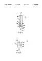
- FIG. 4is a cross-sectional view of a stylus of the FIG. 1 embodiment.
- FIG. 5is a cross-sectional view of a transducer device utilized in the FIG. 1 embodiment and in other embodiments of the invention.
- FIG. 6is a block diagram of circuitry of the FIG. 1 embodiment and which can be used in other embodiments of the invention.
- FIG. 7illustrates a further embodiment of the invention that utilizes separate housings.
- FIG. 8illustrates a further embodiment of the invention that utilizes clamp-on transducer devices.
- FIGS. 9 and 10illustrate improvements in accordance with a further form of the invention which is useful in reducing undesired reflections of ultrasonic energy.
- the apparatusincludes an elongated housing 110 which, in one mode of operation, can be positioned generally adjacent an edge of a region in which the position of a movable element 150 is to be determined.
- the housing 110which is further shown in FIGS. 2 and 3, has mounted in the bottom thereof spaced apart transducers devices 121 and 122, which have respective tapered tips 121A and 122A that also serve as two of the feet of the housing 110.
- a third foot 126, of rubber,is visible in FIGS. 2 and 3. If desired, two or more spaced apart rubber feet can be used.
- the tips (narrow ends) 121A and 122A of the transducer devicescontact or couple to the surface of a solid material 105 which may be, for example, the top of a Formica table, a glass platen or other glass surface, a solid plastic surface, or any other solid surface that will transmit sonic or ultrasonic energy without undue attenuation.
- a solid material 105which may be, for example, the top of a Formica table, a glass platen or other glass surface, a solid plastic surface, or any other solid surface that will transmit sonic or ultrasonic energy without undue attenuation.
- the moveable element 150which is illustrated as being a stylus in the present embodiment, is moveable over the surface of solid medium 105 and has a tip 157 which contacts the surface and can be used to designate or draw points or lines (sequences of points) on the surface.
- a cursor or other types of moveable elementcan alternatively be employed.
- the stylusshown in further detail in FIG. 4, includes an elongated pen-like body 151, which may be formed of plastic, that houses a transducer device 159.
- the device 159includes a cylindrical body which has a wafer 152 of piezoelectric material, such as lead metaniobate, mounted therein beneath an acoustic absorber 153.
- the transducer 152has electrodes formed on opposing sides thereof.
- a horn-shaped interface/tip 154is secured to the bottom of the transducer 152, such as with a plastic adhesive.
- the material of the hornpreferably has an acoustic impedance that is between the acoustic impedance of the transducer 152 and the acoustic impedance of the solid medium 105.
- an aluminum tipis used.
- a contact 157formed of a resilient material such as Teflon, can be employed to facilitate sliding of the tip on the surface of the solid medium 105.
- Conductors 171are coupled through a cable 162 to circuitry in the housing 110 (FIG. 1).
- the stylus 150can also be provided with a button that controls a microswitch 165 that the operator can use to designate specified points.
- the conductors 173, coupled to the microswitch 165,are also carried by the cable 162 to circuitry in the housing 110.
- transducer device 121 or 122there is shown an embodiment of a type of transducer device 121 or 122 that can be utilized in the housing 110 and in other embodiments hereof.
- the transducer devicecan have a construction similar to that of the transducer device 159 in the moveable element, as previously described in conjunction with FIG. 4.
- a cylindrical body 508contains the piezoelectric disc 510, which has electrodes on opposing surfaces thereof.
- an acoustic absorber 512can be mounted over the piezoelectric disc, to serve as a base for the transducer disc and to dampen reflections above the transducer disc, and a horn-shaped interface/tip 121A is secured to the bottom of transducer 510.
- the material of the hornpreferably has an acoustic impedance between the acoustic impedance of the transducer material and the acoustic impedance of the solid medium.
- the tipcontacts the surface over an area that is less than 2 mm 2 , and, preferably, less than 0.5 mm 2 .
- Conductors 575couple the transducer electrodes to circuitry in the housing 110.
- the body 508can be provided with threading, as shown at 540, which can engage suitable threading in a recess in the bottom of housing 110 for mounting therein.
- a resilient mountingcan alternatively be used to provide a degree of mechanical isolation of the transducer device from the housing.
- an electrical signalis applied across the stylus transducer's electrodes.
- the resultant vibration of the piezoelectric transducer elementtravels down the horn to the tip thereof, and the vertical component of the tip's motion results in establishment of a shear wave in the solid medium.
- the shear mode energy in the solid mediumis received at the transducer devices 121 and 122 in the housing 110.
- the shear mode energy in the solid mediumcauses a vibration at the tip of the horn of each device, which travels up the horn and results in a vibration at the piezoelectric transducer, which, in turn, causes an electrical potential across the electrodes thereof.
- the travel time in the solid mediumis measured, and since the speed of the ultrasonic shear wave in the solid medium is known (or can be determined empirically), the distance between the tip of the moveable element and the tips of the transducer devices in the housing 110 can be computed. From the two distances, the coordinates of the tip of the moveable element can be determined (see, for example, U.S. Pat. Nos. 4,012,588 and 4,357,672).
- so-called "reverse mode" transmission through a solid mediumcan alternatively be employed, and reverse mode is applicable to the various embodiments hereof.
- the ultrasonic energycan be transmitted (e.g. alternately, or at different frequencies) from the transducer devices in the housing 110, and received at the transducer device in the moveable element.
- FIG. 6shows a block diagram of circuitry, some or all of which can be contained in the housing 110.
- a companion systemsuch as a processor, represented at 600, can be used to receive and process the positional information for any desired purpose and, if desired, to trigger operation of the digitizer apparatus and to control when it operates.
- the output of a high frequency oscillator 651is coupled, via gate 652 and isolator 653, to the transducer 152 in stylus 150.
- the outputs of the transducer devices 121 and 122are coupled via conductors 575 and 575' to amplifiers 671 and 672, respectively.
- the outputs of amplifiers 671 and 672are respectively coupled to threshold discriminator circuits 681 and 682, which may be of a type known in the art, that are used to detect the first arrival of the ultrasonic signal at the transducers.
- the pulse generator signal which is operative to enable the gate 652is also applied to the reset and enable terminals of a first counter 691 and a second counter 692. Clock pulses from a basic clock 695 are counted by the counters 691 and 692 upon being enabled.
- the output of threshold discriminators 681 and 682are respectively coupled to the disable terminals of first counter 691 and second counter 692.
- the outputs of these countersare respectively coupled to output buffers 697 and 698, which are enabled to read out the counter values by the same signal which disables the counters.
- the buffer outputsare typically coupled to a companion system, such as processor 600 which may be, for example, part of a personal computer system. Other circuitry and electronic processing techniques can alternatively be employed.
- the first counter 691 and the second counter 692are enabled to start counting clock pulses from the clock 695.
- the counters 691 and 692are respectively disabled and their counts are caused to be read out via output buffers 697 and 698.
- the countsrespectively represent the distance between the stylus tip and the tip 121A of the transducer device 121, and the distance between the stylus tip and the tip 122A of the transducer device 122.
- FIG. 7there is shown an embodiment of the invention wherein two separate housings, 710 and 720, are used and each contains at least one transducer device.
- the housingsrespectively contain the transducer devices 121 and 122, as previously described.
- Each housingcan also have a plurality of rubber feet (not visible).
- the embodiment of FIG. 7has a cable 735 providing electrical communication between the two housings.
- the stylus cable 162is coupled with housing 720, and the housing 720 is coupled with processor 600.
- the circuitry of the FIG. 1 embodiment(as shown in FIG. 6) can be utilized herein, and can be located, for example, in either housing or in both housings. With the present embodiment, the working area is not limited by the length of the bar, as in the FIG. 1 embodiment.
- each of the units and/or the styluscan have direct electrical connection with the processor 600. Wireless communication could also be used.
- the transducer tips 121A and 122Acan, for example, be positioned at known or measured locations. In the illustration of FIG. 7, the transducer device tips are positioned along a predetermined straight line, a measured distance D apart.
- Various types of calibrationcan also be used to precisely determine the distance between transducers (see such as U.S. Pat. No. 4,956,824).
- the moveable elementcan be used in a pre-operation calibration routine by placing it at (or a known distance from) the position or planned position of a transducer device 121 or 122.
- the transducer devices 121 and/or 122could also be adapted to transmit as well as receive, for calibration purposes.
- FIG. 8there is shown a further embodiment of the invention which can be employed to advantage when there is easy access to an edge 105E of the solid medium 105.
- the transducer devices 121 and 122(not visible) are respectively mounted in housings 710 and 720, as in the previous embodiment, and the housings have respective clamping assemblies 831 and 832 that are adapted to clamp to an edge of the solid medium so that the tips 121A and 122A are pressed against the surface of the solid medium.
- the transducer devices and the stylus 150are coupled by cables to a housing 800 that can contain the previously described electronics and/or, if desired, with processor 600. Considerations of transducer placement and/or calibration are similar to those described in conjunction with FIG. 7.
- a paper having markings to be digitizedcan be placed on the solid medium, and coupling of ultrasonic energy to and/or from the solid medium can be achieved through the paper. If the paper is not unduly thick, sufficient energy will be coupled between the transducer device and the solid medium. For example, in one mode of use, both the moveable element transducer device and the temporarily fixed transducer devices may be on paper. However, in most instances where paper is being used, the temporarily fixed transducers may be located beyond the edge of the paper, so that only the transducer device in the moveable element will need to couple ultrasonic energy through the paper to and/or from the solid medium.
- reflection reducing meansare provided at at least some of the edges of the solid medium and, preferably, at all the edges thereof.
- FIG. 9illustrates an embodiment of reflection reducing means on the edges of a solid medium 905 being used for transmission of ultrasonic energy for coordinate position determination.
- a pattern of teethhas been found to be effective.
- the edges 906,907 of the solid mediumhave a sawtooth shape. Other shapes of teeth can be used. The teeth prevent direct reflections to the receivers, and multiple reflections generally arrive too late to cause problems.
- each reflectionhas an associated attenuation that tends to attenuate the multiple reflected energy.
- the spacing d between adjacent teethshould be at least as large as the wavelength at the center frequency of the ultrasonic energy in the solid medium. If the spacing is too small, the energy will tend to reflect more directly.
- the pattern of teethcan be formed as a recess in the material which will define an edge thereof, as illustrated in FIG. 10.
- the recesscan extend through most of the thickness of the solid medium and, if desired, can be filled with a material that absorbs the sonic energy, as represented by the reference numeral 915.
- the materialshould preferably be lossy and have an acoustic impedance close to that of the solid medium to minimize reflections.
- a tungsten-filled epoxycan be used.
- transducer device configurationscan be utilized to transmit and/or receive ultrasonic energy to and/or from the solid medium via a tip.
Landscapes
- Engineering & Computer Science (AREA)
- Physics & Mathematics (AREA)
- General Engineering & Computer Science (AREA)
- Theoretical Computer Science (AREA)
- Acoustics & Sound (AREA)
- Human Computer Interaction (AREA)
- General Physics & Mathematics (AREA)
- Length Measuring Devices Characterised By Use Of Acoustic Means (AREA)
Abstract
Description
Claims (21)
Priority Applications (3)
| Application Number | Priority Date | Filing Date | Title |
|---|---|---|---|
| US08/003,786US5379269A (en) | 1993-01-13 | 1993-01-13 | Position determining apparatus |
| PCT/US1994/000577WO1994016422A1 (en) | 1993-01-13 | 1994-01-12 | Position determining apparatus |
| TW083100231ATW253043B (en) | 1993-01-13 | 1994-01-13 |
Applications Claiming Priority (1)
| Application Number | Priority Date | Filing Date | Title |
|---|---|---|---|
| US08/003,786US5379269A (en) | 1993-01-13 | 1993-01-13 | Position determining apparatus |
Publications (1)
| Publication Number | Publication Date |
|---|---|
| US5379269Atrue US5379269A (en) | 1995-01-03 |
Family
ID=21707599
Family Applications (1)
| Application Number | Title | Priority Date | Filing Date |
|---|---|---|---|
| US08/003,786Expired - Fee RelatedUS5379269A (en) | 1993-01-13 | 1993-01-13 | Position determining apparatus |
Country Status (3)
| Country | Link |
|---|---|
| US (1) | US5379269A (en) |
| TW (1) | TW253043B (en) |
| WO (1) | WO1994016422A1 (en) |
Cited By (27)
| Publication number | Priority date | Publication date | Assignee | Title |
|---|---|---|---|---|
| US5648643A (en)* | 1995-06-16 | 1997-07-15 | Knowles; Terence J. | Acoustic wave touch panel with inlayed, etched arrays and method of making the panel |
| US5691959A (en)* | 1994-04-06 | 1997-11-25 | Fujitsu, Ltd. | Stylus position digitizer using acoustic waves |
| AU718394B2 (en)* | 1997-02-21 | 2000-04-13 | Electronics For Imaging, Inc. | Retrofittable apparatus for converting a substantially planar surface into an electronic data capture device |
| US6100877A (en)* | 1998-05-14 | 2000-08-08 | Virtual Ink, Corp. | Method for calibrating a transcription system |
| US6104387A (en)* | 1997-05-14 | 2000-08-15 | Virtual Ink Corporation | Transcription system |
| US6111565A (en)* | 1998-05-14 | 2000-08-29 | Virtual Ink Corp. | Stylus for use with transcription system |
| US6124847A (en)* | 1998-05-14 | 2000-09-26 | Virtual Ink, Corp. | Collapsible detector assembly |
| US6147681A (en)* | 1998-05-14 | 2000-11-14 | Virtual Ink, Corp. | Detector for use in a transcription system |
| US6157592A (en)* | 1998-07-06 | 2000-12-05 | Resolution Displays, Inc. | Acoustic position determination method and apparatus |
| US6177927B1 (en) | 1998-05-14 | 2001-01-23 | Virtual Ink Corp. | Transcription system kit |
| US6191778B1 (en) | 1998-05-14 | 2001-02-20 | Virtual Ink Corp. | Transcription system kit for forming composite images |
| US6211863B1 (en) | 1998-05-14 | 2001-04-03 | Virtual Ink. Corp. | Method and software for enabling use of transcription system as a mouse |
| US6292177B1 (en) | 1997-03-05 | 2001-09-18 | Tidenet, Inc. | Marking device for electronic presentation board |
| US6310615B1 (en) | 1998-05-14 | 2001-10-30 | Virtual Ink Corporation | Dual mode eraser |
| US6313829B1 (en)* | 1998-11-02 | 2001-11-06 | The Whitaker Corporation | Edge treatment method for ultrasonic wave absorption |
| US6326565B1 (en) | 1997-02-28 | 2001-12-04 | Electronics For Imaging, Inc. | Marking device for electronic presentation board |
| US20010050677A1 (en)* | 1998-10-21 | 2001-12-13 | Carol Tosaya | Piezoelectric data entry devices |
| US20020054026A1 (en)* | 2000-04-17 | 2002-05-09 | Bradley Stevenson | Synchronized transmission of recorded writing data with audio |
| US20020150151A1 (en)* | 1997-04-22 | 2002-10-17 | Silicon Laboratories Inc. | Digital isolation system with hybrid circuit in ADC calibration loop |
| WO2002091289A1 (en)* | 2001-05-04 | 2002-11-14 | Electronics For Imaging, Inc. | Piezoelectric data entry device |
| US20040180316A1 (en)* | 2003-03-15 | 2004-09-16 | Shih-Chin Yang | Interactive book system based on ultrasonic position determination |
| US20050226437A1 (en)* | 2002-05-27 | 2005-10-13 | Sonicemotion Ag | Method and device for generating information relating to relative position of a set of at least three acoustic transducers (as amended) |
| US20050256689A1 (en)* | 2004-05-13 | 2005-11-17 | Conceptual Assets, Inc. | Method and system for measuring attributes on a three-dimenslonal object |
| US20060149495A1 (en)* | 2005-01-05 | 2006-07-06 | Massachusetts Institute Of Technology | Method for object identification and sensing in a bounded interaction space |
| US20070019182A1 (en)* | 2005-07-20 | 2007-01-25 | Lee Grodzins | Arc/spark optical emission spectroscopy correlated with spark location |
| US20090104590A1 (en)* | 2003-03-15 | 2009-04-23 | Shih-Chin Yang | Interactive book system based on ultrasonic position determination |
| US20140269194A1 (en)* | 2013-03-18 | 2014-09-18 | Inputek Inc. | Three Dimensional Touch by Acoustic Waves |
Families Citing this family (5)
| Publication number | Priority date | Publication date | Assignee | Title |
|---|---|---|---|---|
| US5999689A (en)* | 1996-11-01 | 1999-12-07 | Iggulden; Jerry | Method and apparatus for controlling a videotape recorder in real-time to automatically identify and selectively skip segments of a television broadcast signal during recording of the television signal |
| US7269330B1 (en) | 1996-11-01 | 2007-09-11 | Televentions, Llc | Method and apparatus for controlling a video recorder/player to selectively alter a video signal |
| EP1076893A4 (en)* | 1998-05-14 | 2005-03-09 | Virtual Ink Corp | Transcription system |
| GB2340605B (en)* | 1998-05-14 | 2001-04-11 | Virtual Ink Corp | Transcription system |
| GB2340606B (en)* | 1998-05-14 | 2000-07-12 | Virtual Ink Corp | Transcription system |
Citations (7)
| Publication number | Priority date | Publication date | Assignee | Title |
|---|---|---|---|---|
| US4012588A (en)* | 1975-08-29 | 1977-03-15 | Science Accessories Corporation | Position determining apparatus and transducer therefor |
| US4357672A (en)* | 1980-07-30 | 1982-11-02 | Science Accessories Corporation | Distance ranging apparatus and method |
| US4488000A (en)* | 1982-09-30 | 1984-12-11 | New York Institute Of Technology | Apparatus for determining position and writing pressure |
| US4564928A (en)* | 1982-09-30 | 1986-01-14 | New York Institute Of Technology | Graphical data apparatus |
| US4853496A (en)* | 1987-03-27 | 1989-08-01 | Canon Kabushiki Kaisha | Acoustic coordinate input device using a roughened surface to attenuate the surface wave component |
| US4956824A (en)* | 1989-09-12 | 1990-09-11 | Science Accessories Corp. | Position determination apparatus |
| US5142106A (en)* | 1990-07-17 | 1992-08-25 | Canon Kabushiki Kaisha | Coordinates input apparatus |
- 1993
- 1993-01-13USUS08/003,786patent/US5379269A/ennot_activeExpired - Fee Related
- 1994
- 1994-01-12WOPCT/US1994/000577patent/WO1994016422A1/enactiveApplication Filing
- 1994-01-13TWTW083100231Apatent/TW253043B/zhactive
Patent Citations (7)
| Publication number | Priority date | Publication date | Assignee | Title |
|---|---|---|---|---|
| US4012588A (en)* | 1975-08-29 | 1977-03-15 | Science Accessories Corporation | Position determining apparatus and transducer therefor |
| US4357672A (en)* | 1980-07-30 | 1982-11-02 | Science Accessories Corporation | Distance ranging apparatus and method |
| US4488000A (en)* | 1982-09-30 | 1984-12-11 | New York Institute Of Technology | Apparatus for determining position and writing pressure |
| US4564928A (en)* | 1982-09-30 | 1986-01-14 | New York Institute Of Technology | Graphical data apparatus |
| US4853496A (en)* | 1987-03-27 | 1989-08-01 | Canon Kabushiki Kaisha | Acoustic coordinate input device using a roughened surface to attenuate the surface wave component |
| US4956824A (en)* | 1989-09-12 | 1990-09-11 | Science Accessories Corp. | Position determination apparatus |
| US5142106A (en)* | 1990-07-17 | 1992-08-25 | Canon Kabushiki Kaisha | Coordinates input apparatus |
Non-Patent Citations (2)
| Title |
|---|
| Acoustic Tablet With Lamb Wave, Image Technology Conference, 1980 [In Japanese (6 sheets), with 7 sheet partial translation]. |
| Acoustic Tablet With Lamb Wave, Image Technology Conference, 1980 In Japanese (6 sheets), with 7 sheet partial translation .* |
Cited By (35)
| Publication number | Priority date | Publication date | Assignee | Title |
|---|---|---|---|---|
| US5691959A (en)* | 1994-04-06 | 1997-11-25 | Fujitsu, Ltd. | Stylus position digitizer using acoustic waves |
| US5648643A (en)* | 1995-06-16 | 1997-07-15 | Knowles; Terence J. | Acoustic wave touch panel with inlayed, etched arrays and method of making the panel |
| AU718394B2 (en)* | 1997-02-21 | 2000-04-13 | Electronics For Imaging, Inc. | Retrofittable apparatus for converting a substantially planar surface into an electronic data capture device |
| US6067080A (en)* | 1997-02-21 | 2000-05-23 | Electronics For Imaging | Retrofittable apparatus for converting a substantially planar surface into an electronic data capture device |
| EP0960383B1 (en)* | 1997-02-21 | 2006-08-23 | Luidia, Inc. | Retrofittable apparatus for converting a substantially planar surface into an electronic data capture device |
| US6501461B2 (en)* | 1997-02-21 | 2002-12-31 | Tidenet, Inc. | Retrofittable apparatus for converting a substantially planar surface into an electronic data capture device |
| US6326565B1 (en) | 1997-02-28 | 2001-12-04 | Electronics For Imaging, Inc. | Marking device for electronic presentation board |
| US6292177B1 (en) | 1997-03-05 | 2001-09-18 | Tidenet, Inc. | Marking device for electronic presentation board |
| US7050509B2 (en) | 1997-04-22 | 2006-05-23 | Silicon Laboratories Inc. | Digital isolation system with hybrid circuit in ADC calibration loop |
| US20020150151A1 (en)* | 1997-04-22 | 2002-10-17 | Silicon Laboratories Inc. | Digital isolation system with hybrid circuit in ADC calibration loop |
| US6104387A (en)* | 1997-05-14 | 2000-08-15 | Virtual Ink Corporation | Transcription system |
| US6147681A (en)* | 1998-05-14 | 2000-11-14 | Virtual Ink, Corp. | Detector for use in a transcription system |
| US6124847A (en)* | 1998-05-14 | 2000-09-26 | Virtual Ink, Corp. | Collapsible detector assembly |
| US6191778B1 (en) | 1998-05-14 | 2001-02-20 | Virtual Ink Corp. | Transcription system kit for forming composite images |
| US6310615B1 (en) | 1998-05-14 | 2001-10-30 | Virtual Ink Corporation | Dual mode eraser |
| US6100877A (en)* | 1998-05-14 | 2000-08-08 | Virtual Ink, Corp. | Method for calibrating a transcription system |
| US6177927B1 (en) | 1998-05-14 | 2001-01-23 | Virtual Ink Corp. | Transcription system kit |
| US6111565A (en)* | 1998-05-14 | 2000-08-29 | Virtual Ink Corp. | Stylus for use with transcription system |
| US6211863B1 (en) | 1998-05-14 | 2001-04-03 | Virtual Ink. Corp. | Method and software for enabling use of transcription system as a mouse |
| US6157592A (en)* | 1998-07-06 | 2000-12-05 | Resolution Displays, Inc. | Acoustic position determination method and apparatus |
| US6731270B2 (en) | 1998-10-21 | 2004-05-04 | Luidia Inc. | Piezoelectric transducer for data entry device |
| US20010050677A1 (en)* | 1998-10-21 | 2001-12-13 | Carol Tosaya | Piezoelectric data entry devices |
| US6313829B1 (en)* | 1998-11-02 | 2001-11-06 | The Whitaker Corporation | Edge treatment method for ultrasonic wave absorption |
| US20020054026A1 (en)* | 2000-04-17 | 2002-05-09 | Bradley Stevenson | Synchronized transmission of recorded writing data with audio |
| WO2002091289A1 (en)* | 2001-05-04 | 2002-11-14 | Electronics For Imaging, Inc. | Piezoelectric data entry device |
| US7272073B2 (en)* | 2002-05-27 | 2007-09-18 | Sonicemotion Ag | Method and device for generating information relating to the relative position of a set of at least three acoustic transducers |
| US20050226437A1 (en)* | 2002-05-27 | 2005-10-13 | Sonicemotion Ag | Method and device for generating information relating to relative position of a set of at least three acoustic transducers (as amended) |
| US20040180316A1 (en)* | 2003-03-15 | 2004-09-16 | Shih-Chin Yang | Interactive book system based on ultrasonic position determination |
| US20090104590A1 (en)* | 2003-03-15 | 2009-04-23 | Shih-Chin Yang | Interactive book system based on ultrasonic position determination |
| US20050256689A1 (en)* | 2004-05-13 | 2005-11-17 | Conceptual Assets, Inc. | Method and system for measuring attributes on a three-dimenslonal object |
| US20060149495A1 (en)* | 2005-01-05 | 2006-07-06 | Massachusetts Institute Of Technology | Method for object identification and sensing in a bounded interaction space |
| US7474983B2 (en)* | 2005-01-05 | 2009-01-06 | Massachusetts Institute Of Technology | Method for object identification and sensing in a bounded interaction space |
| US20070019182A1 (en)* | 2005-07-20 | 2007-01-25 | Lee Grodzins | Arc/spark optical emission spectroscopy correlated with spark location |
| US7391508B2 (en) | 2005-07-20 | 2008-06-24 | Thermo Niton Analyzers Llc | Arc/spark optical emission spectroscopy correlated with spark location |
| US20140269194A1 (en)* | 2013-03-18 | 2014-09-18 | Inputek Inc. | Three Dimensional Touch by Acoustic Waves |
Also Published As
| Publication number | Publication date |
|---|---|
| WO1994016422A1 (en) | 1994-07-21 |
| TW253043B (en) | 1995-08-01 |
Similar Documents
| Publication | Publication Date | Title |
|---|---|---|
| US5379269A (en) | Position determining apparatus | |
| US4758691A (en) | Apparatus for determining the position of a movable object | |
| US4488000A (en) | Apparatus for determining position and writing pressure | |
| CA1207883A (en) | Graphical data apparatus | |
| EP0123043B1 (en) | Velocity sensing cursor control device and method | |
| EP0169538B1 (en) | Tablet type coordinate input apparatus using elastic waves | |
| US4654648A (en) | Wireless cursor control system | |
| US3134099A (en) | Ultrasonic data converter | |
| JP3764183B2 (en) | Stylus position digitizer using sound waves | |
| US3692936A (en) | Acoustic coordinate data determination system | |
| JP2535626B2 (en) | Coordinate input device | |
| EP0755020A2 (en) | Vibration-transmitting tablet and coordinate-input apparatus using said tablet | |
| US5050134A (en) | Position determining apparatus | |
| JPH07160408A (en) | Piezoelectric sensor and coordinate input device using the same | |
| EP0107922A1 (en) | Graphical data apparatus | |
| JPS6083126A (en) | Coordinate detector for input position | |
| KR930003168B1 (en) | Input device of tablet type | |
| JPS6139121A (en) | Reading device for coordinate position information | |
| GB2179152A (en) | Coordinate reading apparatus | |
| JPS61281324A (en) | Ultrasonic application tablet | |
| JP3822867B2 (en) | Stylus for ultrasonic detector | |
| JPH01114926A (en) | Coordinate input device | |
| KR100558140B1 (en) | Structure Analysis and / or Position Detection Apparatus and Method for Film-like Subjects | |
| JPH0512820Y2 (en) | ||
| JPS6133523A (en) | Position orienting device utilizing elastic wave |
Legal Events
| Date | Code | Title | Description |
|---|---|---|---|
| AS | Assignment | Owner name:SCIENCE ACCESSORIES CORP., CONNECTICUT Free format text:ASSIGNMENT OF ASSIGNORS INTEREST.;ASSIGNORS:SINDEBAND, SEYMOUR J.;STONE, THOMAS L.;REEL/FRAME:006502/0008 Effective date:19930226 | |
| LAPS | Lapse for failure to pay maintenance fees | ||
| FP | Lapsed due to failure to pay maintenance fee | Effective date:19990103 | |
| AS | Assignment | Owner name:MCG FINANCE CORPORATION, VIRGINIA Free format text:SECURITY AGREEMENT;ASSIGNOR:GTCO CORPORATION;REEL/FRAME:010070/0137 Effective date:19990201 | |
| AS | Assignment | Owner name:FIRST UNION NATIONAL BANK, A CORPORATION OF NORTH Free format text:SECURITY INTEREST;ASSIGNOR:GTCO CORPORATION;REEL/FRAME:010514/0611 Effective date:19991227 | |
| AS | Assignment | Owner name:FIRST UNION NATIONAL BANK, VIRGINIA Free format text:SECURITY INTEREST;ASSIGNOR:GTCO CORPORATION;REEL/FRAME:010547/0449 Effective date:20000225 | |
| AS | Assignment | Owner name:GTCO CORPORATION, MARYLAND Free format text:RELEASE OF SECURITY INTEREST;ASSIGNOR:MCG FINANCE CORPORATION;REEL/FRAME:010696/0359 Effective date:20000112 | |
| AS | Assignment | Owner name:GTCO CORPORATION, MARYLAND Free format text:MERGER;ASSIGNOR:SCIENCE ACCESSORIES CORPORATION;REEL/FRAME:020083/0106 Effective date:19951222 | |
| AS | Assignment | Owner name:GTCO CORPORATION, TEXAS Free format text:RELEASE BY SECURED PARTY;ASSIGNOR:WACHOVIA BANK, NATIONAL ASSOCIATION, FKA FIRST UNION NATIONAL BANK;REEL/FRAME:020299/0585 Effective date:20071228 | |
| STCH | Information on status: patent discontinuation | Free format text:PATENT EXPIRED DUE TO NONPAYMENT OF MAINTENANCE FEES UNDER 37 CFR 1.362 |