US5379214A - Method for reading the concentration of a medically significant component of a biological fluid from a test strip - Google Patents
Method for reading the concentration of a medically significant component of a biological fluid from a test stripDownload PDFInfo
- Publication number
- US5379214A US5379214AUS08/140,601US14060193AUS5379214AUS 5379214 AUS5379214 AUS 5379214AUS 14060193 AUS14060193 AUS 14060193AUS 5379214 AUS5379214 AUS 5379214A
- Authority
- US
- United States
- Prior art keywords
- instrument
- strip
- remission
- transmitting
- chemistry
- Prior art date
- Legal status (The legal status is an assumption and is not a legal conclusion. Google has not performed a legal analysis and makes no representation as to the accuracy of the status listed.)
- Expired - Lifetime
Links
Images


Classifications
- G—PHYSICS
- G01—MEASURING; TESTING
- G01N—INVESTIGATING OR ANALYSING MATERIALS BY DETERMINING THEIR CHEMICAL OR PHYSICAL PROPERTIES
- G01N21/00—Investigating or analysing materials by the use of optical means, i.e. using sub-millimetre waves, infrared, visible or ultraviolet light
- G01N21/01—Arrangements or apparatus for facilitating the optical investigation
- G—PHYSICS
- G01—MEASURING; TESTING
- G01N—INVESTIGATING OR ANALYSING MATERIALS BY DETERMINING THEIR CHEMICAL OR PHYSICAL PROPERTIES
- G01N35/00—Automatic analysis not limited to methods or materials provided for in any single one of groups G01N1/00 - G01N33/00; Handling materials therefor
- G01N35/00584—Control arrangements for automatic analysers
- G—PHYSICS
- G01—MEASURING; TESTING
- G01N—INVESTIGATING OR ANALYSING MATERIALS BY DETERMINING THEIR CHEMICAL OR PHYSICAL PROPERTIES
- G01N35/00—Automatic analysis not limited to methods or materials provided for in any single one of groups G01N1/00 - G01N33/00; Handling materials therefor
- G01N35/00029—Automatic analysis not limited to methods or materials provided for in any single one of groups G01N1/00 - G01N33/00; Handling materials therefor provided with flat sample substrates, e.g. slides
- G01N2035/00099—Characterised by type of test elements
- G01N2035/00108—Test strips, e.g. paper
- G—PHYSICS
- G01—MEASURING; TESTING
- G01N—INVESTIGATING OR ANALYSING MATERIALS BY DETERMINING THEIR CHEMICAL OR PHYSICAL PROPERTIES
- G01N35/00—Automatic analysis not limited to methods or materials provided for in any single one of groups G01N1/00 - G01N33/00; Handling materials therefor
- G01N35/00584—Control arrangements for automatic analysers
- G01N35/00722—Communications; Identification
- G01N35/00871—Communications between instruments or with remote terminals
- Y—GENERAL TAGGING OF NEW TECHNOLOGICAL DEVELOPMENTS; GENERAL TAGGING OF CROSS-SECTIONAL TECHNOLOGIES SPANNING OVER SEVERAL SECTIONS OF THE IPC; TECHNICAL SUBJECTS COVERED BY FORMER USPC CROSS-REFERENCE ART COLLECTIONS [XRACs] AND DIGESTS
- Y10—TECHNICAL SUBJECTS COVERED BY FORMER USPC
- Y10S—TECHNICAL SUBJECTS COVERED BY FORMER USPC CROSS-REFERENCE ART COLLECTIONS [XRACs] AND DIGESTS
- Y10S128/00—Surgery
- Y10S128/92—Computer assisted medical diagnostics
Definitions
- This inventionrelates to apparatus and methods for reading the concentration of a medically significant component of a biological fluid from a test strip. It is disclosed in the context of an apparatus and a method for reading the concentration of glucose in blood reacted on a test strip with a chemistry with which the strip has previously been treated.
- the problems with such stripsonly begin with dosing the strips with the bodily fluid or fluids to be analyzed.
- the chemistriesare reactants with the medically significant component(s) of the fluids. These reactants react with the medically significant component(s) resulting typically in some colorimetric indication of the concentration of the medically significant component of the fluid. However, these reactions continue, typically for extended times, until all of the reactants have reacted. Consequently, it is generally necessary to time the reaction of the medically significant component with the strip chemistry so that a colorimetric comparison of the reacted strip chemistry to a standard on a color chart can be made at some established time after the reaction is initiated by depositing the fluid on the strip. Otherwise, if the reaction is not permitted to proceed long enough, or is permitted to proceed too long, the color corresponding to the extent of the reaction will not match the correct standard on the chart.
- the present inventionmakes use of an endpoint chemistry system of the type described in U.S. Pat. No. 4,929,545.
- the disclosure of U.S. Pat. No. 4,929,545is incorporated herein by reference.
- the advantages of an endpoint chemistryare clear. For the user who frequently has poor eyesight and/or manual dexterity, there is no need to be concerned about how long the reaction has proceeded. The reaction reaches an endpoint in relatively short order after which there is no significant shift in the color of the reaction products on the strip.
- a methodfor communicating with one or more microcomputer controlled instruments for determining the concentration of a medically significant component of a body fluid.
- Each instrumentincludes a port through which instructions and data can be received from, and transmitted to, an external device.
- the methodcomprises the steps of transmitting to each instrument an attention protocol for advising each instrument that a further instruction is to be transmitted, transmitting one of a global address to all of such instruments and an address unique to one of such instruments, and transmitting an instruction to all or to said one instrument.
- the step of transmitting the attention protocolcomprises either the step of transmitting a first attention protocol (if the instruments are activated and in a state in which they are capable of determining the concentration of the medically significant component) or the step of transmitting a second attention protocol (if the instruments are inactivated and not in a state in which they are capable of determining the concentration of the medically significant component).
- the step of transmitting an instructioncomprises the step of transmitting one of a command and a request.
- the methodfurther comprises the step of transmitting a key for permitting the instrument or instruments addressed to respond to the command.
- the steps of transmitting a key and a command togethercomprise the step of first transmitting the key for permitting the instrument or instruments addressed to receive the command and then transmitting the command for causing the instrument or instruments addressed to respond to the command.
- the instrumentincludes a programmable non-volatile memory and the instruction comprises instrument calibration information for storage in the non-volatile memory.
- the methodfurther comprises the steps of reading the calibration information from the non-volatile memory, comparing that information to information contained in a volatile memory in the microcomputer, and generating an error message in response to an unfavorable comparison.
- FIGS. 1-8illustrate exploded perspective views, from various different angles, of various components of an instrument constructed according to the present invention
- FIG. 9illustrates a partly block and partly schematic circuit diagram of the electric circuit of the instrument illustrated in FIGS. 1-8;
- FIG. 10illustrates a type of flow diagram useful in understanding the operation of the instrument illustrated in FIGS. 1-8;
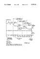
- FIG. 11illustrates a % remission versus time curve useful in understanding the operation of the software of the instrument of FIGS. 1-9;
- FIG. 12illustrates another % remission versus time curve useful in understanding the operation of the software of the instrument of FIGS. 1-9;
- FIG. 13illustrates an address and segment map useful in understanding the meter according to the present invention
- FIG. 14illustrates a protocol for communicating with a meter according to the present invention.
- an instrument 10includes a case 12 having a front portion 14, a rear portion 16, a key housing portion 18 and a strip carrier holder portion 20.
- a printed circuit board 22the contents of which will be considered in more detail in the discussion of FIG. 9, is sandwiched generally between the front and rear portions 14, 16, respectively.
- Front portion 14includes a relief 24 of generally trapezoidal configuration at the center of which is a generally circular opening 26.
- a generally right circular cylindrical stem 28extends downwardly from the underside of front portion 14 beneath opening 26. This stem 28 slidably receives a stem 30 provided on the back of an ON/OFF button 32 of the same shape as relief 24.
- stem 30is split axially and somewhat frustoconical in configuration so that button 32 is captured in relief 24 when stem 30 is pushed into opening 26 until the split, frustoconical end 36 of stem 30 clears the bottom end 38 of stem 28.
- the portion of stem 30 above end 36is somewhat longer than stem 28 so that some movement of button 32 vertically in relief 24 is possible.
- Front casing portion 14also includes a wall 40 inside of, and parallel with, a region 42 of an end wall thereof.
- Wall 40includes a vertically extending groove 44 open at its bottom 46 and with a semicircular top 48.
- a memory button 50has ribs 52 on its back wall spaced apart slightly less than the width of groove 44.
- Button 50 excluding ribs 52is slightly thicker than the space between wall 40 and region 42.
- the flexible resin construction of front portion 14 and a circular opening 54 of slightly larger diameter than button 50 in region 42permits the wall 40 to flex away from region 42 as button 50 is forced into the space between them and snaps into place protruding through opening 54.
- a flange 56 on button 50keeps it from going all the way through opening 54 and falling from front portion 14.
- the front and rear portions 14, 16include respective, cooperating, somewhat arcuate cutouts 60, 62 (FIGS. 1, 6 and 8), for key housing portion 18.
- Key housing portion 18is designed to receive an electronically readable information carrier, or key, 64 (FIG. 2) of the type described in U.S. Pat. No. 5,053,199. The disclosure of U.S. Pat. No. 5,053,199 is incorporated herein by reference.
- Front and rear portions 14, 16also include cooperating cutouts 68, 70 (FIGS. 1, 6 and 8) for receiving the strip carrier holder portion 20.
- Front portion 14also includes a window 74 (FIGS. 1 and 8) around which a liquid crystal display 76-supporting bezel 78 (FIGS. 3 and 7) fits on the inside of front portion 14.
- Bezel 78mounts the LCD 76 so as to be visible through window 74 and provides the necessary electrical connections 79 to LCD 76.
- the back portion 16 of the case 12also includes means for mounting a piezoelectric beeper transducer 80 (FIG. 6) and for providing electrical contact 81 thereto and a battery housing cutout 82 having a pivotally mounted door 84 for convenient insertion and removal of a six-volt battery 86.
- the lips 88, 90 of front and back portions 14, 16, respectively,are complementarily configured to snap together.
- a self tapping screw 92(FIG. 1) through back portion 16 and into a stem 94 molded on the inside of front portion 14 holds portions 14, 16 together.
- Screw 92extends through a hole 96 provided therefor in printed circuit board 22, which, along with the configurations of the interiors of front and back portions 14, 16, holds board 22 in place.
- the strip carrier holder portion 20includes an outer case portion 100 provided with grooves 102 (FIG. 4) on its top and bottom surfaces to aid in gripping it and snapping it into and out of engagement with the front 14 and back 16 case portions.
- Case portion 100is provided with an opening 104 for inserting chemistry strips 106, the remissions of which are to be read, into the instrument 10.
- the margins 108 of opening 104are somewhat funnel-shaped to assist in insertion of the strips 106 into the instrument 10 in the correct orientation.
- a pair of somewhat pawl-shaped members 110extend rearwardly of case portion 100 beneath opening 104.
- a strip carrier body 120includes a lower web portion 122 along each of the opposite sides of which extend two guide ribs 124. Web portion 122 is only slightly thinner than slot 112 is for most of its length. Guide ribs 124 are spaced apart only slightly further than the vertical thickness of each of members 110. These dimensions permit strip carrier body 120 to be slid into the slot 112 defined between members 110.
- a triangular horizontal cross section projection 126 spaced an appropriate distance along web portion 122 on each side thereof between guide ribs 124cooperates with region 114 on case portion 100 to lock strip carrier body 120 between members 110.
- strip carrier body 120Near its end remote from case portion 100, strip carrier body 120 includes a pair of horizontally projecting ears 130, each of which is provided with an elongated slot 132. Slots 132 extend generally transversely to the directions of motion of strips 106 as the strips are inserted into opening 104 and into the strip carrier holder 20 and removed therefrom.
- a lift 134includes a pair of vertically, oppositely extending trunnions 136 which engage in respective slots 132 to permit lift 134 to move away from strip carrier body 120 as a strip 106 to be read is inserted therebetween.
- Lift 134in turn, includes a pair or horizontally extending ears 138 at its forward end opposite the end at which trunnions 136 are provided.
- Each ear 138is provided with a vertically extending circular cross section hole 140.
- a high reflectance (remission) white tile 142is provided with a pair of trunnions 144 by which it is pivotally attached, by insertion of trunnions 144 into respective holes 140, to lift 134.
- strip carrier body 120is provided with a slot 152.
- Strip carrier body 120is also provided with another slot 154 between slot 152 and case portion 100, and with a frustoconical relief 156 (illustrated only in FIG. 1) on the side thereof opposite the side to which lift 134 is attached.
- An optics assembly 160(FIGS. 1, 3 and 5) mounted on the printed circuit board 22 cooperates with the strip carrier holder portion 20.
- the cooperation of these two componentsnegates any possible misalignment errors between the optics and the strips 106.
- This cooperationis aided by the designs and tolerances of some of the molded plastics parts from which the strip carrier holder portion 20 and optics assembly 160 are largely constructed. These designs and tolerances permit the components of the strip carrier holder portion 20 and optics assembly 160 which must be properly aligned for accurate reading of the reacted strips' 106s' remissions to align properly when the strip carrier holder portion 20 is assembled into the instrument case 12.
- Optics assembly 160includes an optics housing 162.
- Housing 162houses a leaf spring 168 and, across from spring 168, a wall 170 against which the spring 168 forces the strip carrier body 120 to position it and its related components 134, 142 and a strip 106 carried thereby properly relative to the instrument 10's optics.
- a frustoconical projectionprojecting toward spring 168 from wall 170 adjacent the inner end 171 of housing 162 engages relief 156 on strip carrier body 120 when strip carrier body 120 is correctly positioned in optics housing 162.
- a pair 174, 176(FIG. 3) of transparent plastic prisms, molded as a single piece 177, are mounted on printed circuit board 22 in separate internal regions 178, 180, respectively, (FIG.
- LED 182is the initiation, or "upstream" end, of a glucose measurement channel.
- Wall 170is provided with a vertical slit opening 190 opposite the opening of socket 186 into housing 162.
- this slit opening 190is directly adjacent prism 174, the smaller of the two prisms provided by piece 177.
- prism 174is oriented at an angle to the surface of the strip 106 other than the angle of incidence of light from LED 182 onto, or the angle of reflection of light from LED 182 from, strip 106.
- prism 174is oriented at an angle of about 77° to the surface of strip 106.
- Prism 176is oriented directly adjacent a slit opening 191 through wall 170 in the assembled optics assembly 160.
- the problem of obtaining a diffuse or remission light component of the light reflected from strip 106is not so great with the light entering prism 176 as it is with the light entering prism 174 because the light entering prism 176 is used only to determine whether there is a strip in strip carrier body 120, and, if so, whether the strip is properly oriented with its chemistry immediately opposite opening 190 and prism 174. Since prism 176 is not in the chemistry reading channel 164, the remission reading from it is not so critical.
- Both of prisms 174, 176have curved faces facing strip 106. These curved faces function as lenses to focus the light remissions entering the prisms on the devices which detect these remissions.
- the lenses incorporated into prisms 174, 176in other words, have focal lengths equal to the distances from the lenses to their respective regions of interest on the strip 106 and also equal to the distances from the lenses to their respective detector devices.
- ⁇ cmicrocomputer
- the clock for ⁇ c 200is a 4.19 MHz crystal 202 which is coupled across terminals X1-X2 thereof. The terminals of crystal 202 are also coupled through respective 33 pF capacitors to ground.
- the V DD supply for ⁇ c 200is provided by a PNP transistor 204 such as a BC858C, the base of which is coupled through a 62 K ⁇ resistor 206 to terminal P4.1 of ⁇ c 200.
- the emitter of transistor 204is coupled to positive battery voltage (+6VDC), hereinafter referred to as VBAT.
- V DDappears at the collector of transistor 204.
- the collector of transistor 204is coupled to its emitter by the parallel combination of two 200 ⁇ resistors.
- the cathode of a diode 208is coupled to the collector of transistor 204.
- the anode of diode 208is coupled to ground.
- Diode 208illustratively is a type 1N4148 diode.
- the RESET terminal of ⁇ c 200is coupled to the collector of a transistor 210 and through a 10 K ⁇ resistor to V DD .
- the emitter of transistor 210is grounded. Its base is coupled through a 22 K ⁇ resistor 212 to the junction of a 0.1 ⁇ F capacitor 214 and a 1M ⁇ resistor 216.
- the other terminal of capacitor 214is coupled to VBAT.
- the other terminal of resistor 216is coupled to ground.
- An electronic log book mode (ELB) connector 220has three terminals. A first of these, 222, is coupled through a 10 K ⁇ resistor to terminals P 3.0/LCDCL and P 0.0/INT4 of ⁇ c 200. Terminal 222 is also coupled to ground through the parallel combination of a 680 pF capacitor and a 220 K ⁇ resistor. Terminal 224 is coupled through a 10 K ⁇ resistor to terminal P3.2 of ⁇ c 200, and to ground through the parallel combination of a 680 pF capacitor and a 220 K ⁇ resistor. Terminal 226 is coupled to ground.
- ELBelectronic log book mode
- the eight terminals 231-238 of the key housing portion 18are coupled, respectively, to: ⁇ c 200's terminal P7.3/KR7; ⁇ c 200's terminal P7.2/KR6; ⁇ c 200's P7.0/KR4; ⁇ c 200's terminal P6.3/KR3; ground; one terminal of a 220 K ⁇ resistor 240, the remaining terminal of which is coupled to terminal 234; nothing (blank); and terminal 236.
- One of these variablesis humidity, and it is taken into consideration by a humidity sensor 242 of standard configuration coupled between ground and an input terminal P0.3/SI/SB1 of ⁇ c 200.
- Humidity sensor 242is also coupled through a 1M ⁇ resistor 244 and a 0.01 ⁇ F capacitor 246 to ground.
- VBATis supplied to the emitter of a PNP transistor 248, illustratively a BC858C.
- the collector of transistor 248is coupled to key housing portion 18's connectors 236 and 238 and to the junction of resistor 244 and capacitor 246.
- An internal EEPROM 250has its CS, SK, DI and DO terminals coupled, respectively, to the P7.1/KR5, P7.2/KR6, P7.0/KR4 and P6.3/KR3 terminals of ⁇ c 200.
- the V CC and ORG terminals of internal EEPROM 250are coupled to the collector of transistor 248.
- the GND terminal of internal EEPROM 250is coupled to ground.
- Internal EEPROM 250illustratively is a Catalyst Semiconductor type CAT93C46 integrated circuit, as is the integrated circuit in code ROM key 64.
- a series string of an 8.2 K ⁇ resistor 252, a 10 K ⁇ resistor 254, a 10 K ⁇ resistor 256, and a 10 K ⁇ resistor 258is coupled between terminal P6.1/KR2 of ⁇ c200 and ground.
- the junction of resistors 252, 254is coupled to terminals VLC0 and BIAS of ⁇ c 200.
- the junction of resistors 254 and 256is coupled to terminal VLC1 of ⁇ c 200.
- the junction of resistors 256 and 258is coupled to terminal VLC2 of ⁇ c 200.
- Transducer 80is coupled across terminal P2.3/BUZ of ⁇ c 200 and ground.
- a diode 260is coupled across transducer 80 with its anode coupled to ground and its cathode coupled to terminal P2.3/BUZ.
- Another diode 262has its anode coupled to terminal P2.3/BUZ and its cathode coupled to V DD .
- COM0-COM2 and DS10-DS0 terminals, respectively, of ⁇ c 200are coupled to respective terminals of the same names, pins 1-14, of LCD 76.
- An infrared strip 106 sensor channel 166includes an LED 264 and a light sensitive transistor (LST) 266 separated by a partition in a common housing (not shown).
- the larger prism 176is mounted on printed circuit board 22 so that its bottom surface rests directly on the top surface of the housing in which LED 264 and LST 266 are housed.
- LED 264 and LST 266illustratively are a Toshiba type TLP908 integrated circuit.
- Light from LED 264shines upward through the bottom of the larger prism 176 and is reflected out through the lens of prism 176 onto the strip 106. The reflected light returns through the lens and is reflected downward within the prism 176 and out the bottom thereof where it is received by LST 266.
- the resultant conductivity of LST 266corresponds to a certain percentage remission of the light from LED 264. That percentage remission establishes whether a strip 106 is present in strip carrier body 120 and, to an extent, whether that strip 106, if present, is properly oriented.
- a current mirror including NPN transistors 268 and 270 in conventional current mirror configurationprovides equal currents through the collectors of these two transistors in response to current flow in the emitter of LST 266.
- a 0.47 ⁇ F capacitor 272is coupled across the collector and emitter of transistor 270 and discharges at a rate determined by the amount of light falling on the base of LST 266 to which LST 266 is sensitive. This configuration subtracts from the initial voltage across capacitor 272 the integral of the light falling on the base of LST 266. Current is supplied to LED 264 for a predetermined, set period of time.
- the remission from strip 106 to the base of LST 266determines how deeply discharged capacitor 272 becomes.
- Capacitor 272is then charged from a constant current source for a period of time which is measured using the system clock, until capacitor 272 has recharged to some reference voltage.
- the length of the period that capacitor 272 takes to recharge to reference voltageis a period of time, a number of strokes of the system clock, and converts to a digital value the percentage remission of channel 166. This translates into the presence or absence of a strip 106 in the strip carrier body 120 and, to an extent, its orientation in strip carrier body 120.
- the instrument 10once it has established that a strip 16 is present in the strip carrier body, next decides whether the strip 106 is properly oriented with its reagent pad in front of slot 190 and prism 174, or whether the strip 106 is backward or upside down.
- the strip architecturemust be such that different ranges of percentage remission readings are presented for these different strip 106 orientations, and this is so. See U.S. Ser. No. 07/661,788.
- the anode of LED 264is coupled to VBAT and its cathode is coupled to the collector of a transistor 276, which illustratively is a type BC848C NPN transistor.
- the emitter of transistor 276is coupled through an 82 ⁇ feedback resistor to ground.
- the base of transistor 276is provided with periodic LED 264 drive signals from terminal P5.1 of ⁇ c 200.
- the base of transistor 276is also coupled through two diode-connected temperature compensation transistors 280, 282 in series to ground.
- Transistors 268, 270, 280, 282illustratively are a type MC3346D quad transistor integrated circuit.
- the emitter of LST 266is coupled to the collector and base of current mirror transistor 268, and to the base of current mirror transistor 270.
- the collector and base of transistor 268 and the base of transistor 270are also coupled to terminal P5.0 of ⁇ c 200.
- the emitters of transistors 268, 270are grounded.
- the collector of transistor 270in addition to being coupled to capacitor 272, is coupled to the inverting (-) input terminal of a difference amplifier 286, and to the collector of a PNP transistor 288 such as a type BC858C transistor.
- the output terminal of difference amplifier 86is coupled to the P3.1/SYNC terminal of ⁇ c 200.
- the emitter of transistor 288is coupled to terminal P5.3 of ⁇ c 200.
- the base of transistor 288is coupled to the output terminal of a difference amplifier 290.
- the inverting (-) and non-inverting (+) input terminals of difference amplifier 290are coupled through a 20 K ⁇ resistor and a 150 ⁇ resistor, respectively, to the collector of LST 266.
- a 5.1 K ⁇ resistoris coupled from the base of transistor 276 to the collector of LST 266 as well.
- the collector of LST 266is coupled to the + input terminal of a difference amplifier 294, the - input terminal of which is coupled through a150 K ⁇ resistor to terminal P6.0/KRO of ⁇ c 200.
- the output terminal of difference amplifier 294is coupled to terminal P3.3 of ⁇ c 200.
- the - input terminal of difference amplifier 294is also coupled through a 0.01 ⁇ F capacitor to ground.
- LED 182is the beginning of channel 164.
- the anode of LED 182is coupled to VBAT and its cathode is coupled to the collector of an NPN transistor 298.
- Transistor 298illustratively is a type BC848C transistor.
- the emitter of transistor 298is coupled through a 120 ⁇ feedback resistor to ground.
- the base of transistor 298is coupled to terminal P5.2 of ⁇ c 200, and through a 20 K ⁇ resistor to the + input terminal of difference amplifier 294.
- the remission of the reagent pad of a strip 106is supplied to a photosensor 300, such as a Siemens type TFA1001W integrated photosensor.
- Photosensor 300is mounted in closely spaced relation to the bottom of the smaller prism 174 so that remissions from the chemistry region of strip 106 that enter the lens surface of prism 174 are reflected down through it and exit from its bottom into photosensor 300.
- Power for photosensor 300is provided through a PNP transistor 302, which illustratively is a type BC858C transistor.
- the emitter of transistor 302is coupled to VBAT. Its base is coupled through a 62K ⁇ resistor to terminal P4.2 of ⁇ c 200. Its collector is coupled to ground through a 22 ⁇ F tantalum capacitor 304.
- the voltage VD1 across capacitor 304is coupled across terminals +VS and -VS of photosensor 300.
- a 0.01 ⁇ F capacitoris also coupled across terminals +VS and -VS.
- the VSTAB and FCOMP terminals of photosensor 300are joined through a 1M ⁇ resistor.
- the VSTAB terminalis also coupled to the + input terminal of a difference amplifier 308.
- difference amplifier 308The - input terminal of difference amplifier 308 is coupled to its output terminal, making it a substantially unity gain amplifier.
- the output terminal of difference amplifier 308is also coupled to the + input terminal of difference amplifier 294.
- Difference amplifiers 286, 290, 294 and 308illustratively are a type LM324A quad difference amplifier integrated circuit.
- Terminal P6.2/KR2is coupled through a 220K ⁇ resistor to the anode of a diode 310 which illustratively is a type IN4148.
- the cathode of diode 310is coupled to the INHIBIT terminal of photosensor 300.
- the conductor extending between the cathode of diode 310 and the INHIBIT terminal of photosensor 300is capacitively coupled through a 680 ⁇ resistor to ground and through a 360 ⁇ resistor to the + input terminal of difference amplifier 286.
- the + input terminal of difference amplifier 286is coupled through a 200 ⁇ resistor to the + input terminal of difference amplifier 290.
- the OUTPUT terminal of photosensor 300is coupled to the - input terminal of difference amplifier 286.
- One terminal of an ON/OFF switch 312 operated by ON/OFF button 32is coupled to ground.
- the other terminal of ON/OFF switch 312is coupled to the P1.1/INT1 terminal of ⁇ c 200.
- the P1.2/INT2 terminal of ⁇ c 200is coupled to one terminal 316 of a memory switch 314 operated by memory button 50.
- Terminal 316 of memory switch 314is coupled through a 220 K ⁇ resistor to ground.
- the other terminal of memory switch 314is coupled through a 220 K ⁇ resistor to the P1.1/INT1 terminal of ⁇ c 200.
- the symbols which can appear on LCD 76include numbers 00.0 through 99.9, the indications mg/dL (milligrams per deciliter), mmol/L (millimoles per liter), mem (which stands for memory), a battery icon, an icon of a blood droplet being deposited on a strip, the word code, and an error icon, a box with an "X" through it, each quadrant of the box being capable of being separately energized.
- the instrument 10is turned on by depressing ON/OFF button 32. Instrument 10 actuates prior to release of ON/OFF button 32. Immediately after the instrument 10 is turned on, it performs 400 a power-on system integrity test and a battery voltage test. If the battery 86 voltage is below 4.5 volts, a battery low warning (battery icon on LCD 76) is displayed. If the battery 86 voltage is below 4.2 volts, the instrument 10 will not turn on 402. Following being turned on, all segments of the display 76, including all icons, are displayed 404 for 2 seconds. If it is enabled, the transducer 80 sounds for the first one/half second of this 2 second display check.
- a battery low warningbattery icon on LCD 76
- the userapplies blood to the strip 106 and allows it to soak into the strip mesh until it is fully absorbed.
- the instrument 10deletes the strip icon, blood drop icon and right arrow icon from display 76, and begins the timing period for the chemistry in the reagent pad of strip 106 to react with the medically significant component, glucose in this example, of the applied blood.
- the display 76sequentially displays 41 (in clockwise rotation) the quadrants on the error or "X" display at a rate of one segment per half second. No timing need be displayed on the instrument 10's LCD 76 because of the employment of an endpoint chemistry on strips 106.
- the instrument 10When the strip 106's reaction is determined by the instrument 10 to have reached an endpoint, the instrument 10 beeps once and then displays 412 a blood glucose value and the mg/dL icon. The instrument 10 also displays the strip icon and left arrow icon to prompt the user to remove the reacted strip 106.
- the glucose resultis stored in the newest (first) memory location, pushing all previously stored glucose readings down one location in memory.
- the instrument 10After the strip 106 is removed, the instrument 10 again rescales itself from the white tile 142 to ready itself for the next strip 106 reading. The instrument 10 then returns to the dosed strip insertion prompt 408.
- the instrument 10can verify that an unreacted strip 106 is acceptable for use. It does this by reading the unreacted strip 106 to make sure that its reagent pad remission value is within the specified percent remission limits stored in the code ROM key 64. Performance of this check is at the user's discretion.
- the instrument 10is capable of performing 410, 414 this check when the instrument is prompting 408 for a dosed strip or during 408, 416, 408, 410, 414 a memory recall display.
- the userremoves an unreacted strip 106 from the vial containing such strips and inserts the unreacted strip 106 into the instrument 10's slot 104 with the reagent pad facing the optics.
- the instrument 10detects the presence of a strip 106 and begins 410 its timing display. During this display, the user must depress 416 the memory button 50 once. This causes the instrument 10 to perform the strip 106 integrity check. After the memory button 50 has been pressed, the instrument 10 will read the strip 106's remission and compare the strip 106's remission against the programmed limits that have been provided by the lot specific ROM key 64.
- Strip 106 integrity approvalis signaled through the strip removal prompt 414 and a single beep. Strip 106 approval permits the user to proceed with a test on a reacted strip 106 by prompting 408 for a dosed strip after the unreacted strip 106 is removed.
- Strip integrity errorsare signaled 418, 420 through the display of the flashing error ("X") icon, flashing strip icon and three beeps.
- the instrument 10remains in this display state until the bad strip 106 is removed. After strip 106's removal, the instrument 10 prompts 408 for a dosed strip.
- Glucose test valuesare stored automatically after every test using "first (oldest) in, first deleted” and “last (newest) in, first recalled” protocols. Once the memory has filled to its thirty reading capacity, each new reading added causes the oldest reading to be deleted from memory.
- Memory recall mode 416is accessible from the dosed strip prompt 408. Memory recall function is initiated by pushing the memory button 50 once. This displays the first memory location (1).
- the displaychanges 422 to display the contents (a glucose reading) of the selected memory location.
- the displayreverts 416 to the memory location display (1 in this example) after 4 seconds. If no button is pushed, the cycle of memory location 416 and memory location contents 422 continues to repeat itself for 5 minutes before the instrument 10 turns itself off.
- the memory display cyclecan also be terminated by the insertion 416, 422, 408 of a test strip 106 into the instrument 10. Recall of the remaining values from memory is accomplished by pressing 408, 416 the memory button 50 over and over again until all thirty stored values and their memory locations have been displayed. Each time the memory button 50 is depressed, the next memory location is displayed. Memory locations and results cycle to location 1 once the user advances beyond the oldest value. If fewer than 30 results are stored in memory, the first location (location 1) is displayed following the last result stored when the memory is advanced beyond the last result. The memory icon is displayed 416, 422 at all times during memory recall.
- the instrument 10reverts 408, 410 to the test/timing mode. Insertion of a strip 106 (reacted or unreacted) automatically causes the instrument 10 to revert to this mode and resets memory to the first (newest) location.
- the instrument 10uses the code ROM key 64 as follows: With the instrument 10 off, the user removes the old ROM key 64 from the instrument 10 and discards it. A new ROM key 64 is packaged in every supply of strips 106. The user inserts the new ROM key 64 containing information pertinent to the new supply of strips 106 into the key housing portion 18 on the instrument 10 prior to turning the instrument 10 on. When the instrument 10 is turned on, the instrument 10 checks the integrity of the data contained in ROM key 64 via a checksum method. If the ROM key 64 data is found to be questionable, then a code error is displayed 424. During the performance 410 of a test, prior to the calculation 412 of a new glucose result, the instrument 10 checks the ROM key 64 to see if it has been changed. If the ROM key 64 has been changed since the instrument 10 was turned on, a code error is displayed 424. The instrument 10 remains in this display until it either times itself off (5 minutes), or is turned off.
- test resultsexceed the upper limit contained in the ROM key 64, then the message HI is displayed in place of a numeric result. If the result does not exceed the lower limit contained in the ROM key 64, LO appears on the display. The mg/dL icon is displayed in both cases.
- Instrument 10verifies the remission of its white tile 142 and signifies a dirty tile 142 by displaying 426 CLE (for "clean") on display 76.
- the instrument 10does not permit the user to begin a testing procedure or memory recall from this display.
- the only remedy for this erroris to turn the instrument 10 off. This error occurs if the slope calculated 406 from the remission of the white tile 142 is not within instrument 10's internal slope limits, typically +5% to -10% of its target value. This error also occurs 408 if the instrument 10 is turned on with a strip 106 inserted in it.
- the instrument 10shuts itself off automatically 5 minutes after the last button push or strip 106 insertion. Automatic shut off occurs regardless of instrument 10 mode or the last button pressed. Depressing ON/OFF button 32 while the instrument 10 is on turns the instrument 10 off.
- Transducer 80provides an audible beep: when the instrument 10 is turned on (0.5 second); when a strip 106 is inserted into opening 104 (0.25 second); whenever an error message is displayed (three times for 0.1 second each); at the end of a test to indicate that a result is displayed or an unreacted strip 106 is usable (0.25 second); and, whenever either button 32 or button 50 is depressed as a "key click" sound (two cycle duration). Transducer 80 actuation can be enabled/disabled by the simultaneous actuation of both ON/OFF button 32 and memory button 50 as the instrument 10 is turned on.
- the instrument 10denotes errors by displaying 428 the "X" icon in combination with an error message or other icon. There are two error types: recoverable and non-recoverable. Strip errors are correctable by removal of the strip 106 from the instrument 10. All other errors are non-recoverable and require the instrument 10 to be turned off in order to clear the error.
- the following errorsare recoverable strip errors. Removal of the strip will cause the instrument 10 to return to the dosed strip prompt 408: the Bad Strip error 418, caused by an improperly reacted strip 106 or a strip 106 which is degraded in any way as to make its state indeterminable; and the Strip in Backwards error 420, caused by the strip 106 being inserted with its blood application side toward the instrument 10's optics.
- the following errorsare non-recoverable, as they are the results of instrument measurement problems: the Dirty Optics error 426, which occurs if the instrument 10's white tile 142 is dirty or degraded, or if the instrument 10 is turned on with a strip 106 already inserted in it; the Electronics Fault error 402, which is caused by the detection of a fault during the instrument 10's power-on self-test or during a diagnostic check; the Strip Removed During Test error 428, which is caused by removing a strip 106 during the performance of a test so that instrument 10 is unable to complete the test cycle; and, the Coding error 424, which is caused by the detection of a code ROM key 64 read error or a mismatch of the lot code number read when instrument 10 is turned on with the lot code number read just prior to the calculation of a glucose result.
- the only remedy for these errorsis to turn the instrument 10 off.
- the instrument 10provides certain prompt messages to the user, including: the Strip Removal prompt, by which the instrument prompts the user to remove a strip 106 by displaying the strip icon and left arrow ( ⁇ ) icon; and the Dosed Strip prompt, by which the instrument 10 prompts the user to insert a dosed strip 106 by displaying the strip icon, right arrow (>) icon, and flashing the blood drop icon. Flashing segments or icons in any mode of operation are displayed for 0.5 second and off for 0.5 second.
- the instrument 10has a diagnostic software package that is accessed via installation of a special diagnostic ROM code key 64.
- the diagnostic ROM code key 64is installed in key housing portion 18 before the instrument 10 is turned on. Once the instrument 10 is turned on with the diagnostic ROM code key installed, the following functions are accessible instead of the normal operating modes.
- instrument 10enters the check strip diagnostic 430.
- the instrumentdisplays dl in the glucose value field, or results field, for one second. After one second the instrument 10 additionally displays the strip icon and right arrow icon to prompt the operator to insert a check strip 106 provided with the diagnostic code ROM key 64. If the user presses memory button 50 during this display, the instrument 10 advances to the next diagnostic test 436.
- the instrument 10Upon insertion 430 of the check strip, the instrument 10 measures the remission of the check strip and compares this remission to a target remission value range stored in the diagnostic code ROM key 64. If the measured remission agrees with the target value range then the results field of the display 76 is blank, transducer 80 beeps once and the user is then prompted 432 to remove the check strip by turning off the right arrow icon, and turning on the left arrow icon while continuing to display the strip icon.
- the instrument 10Upon removal of the check strip from the instrument 10 after a successful check, the instrument 10 returns 430 to the start of the check strip diagnostic routine and remains in this routine until the instrument 10 is turned off, or until the user advances to the next diagnostic routine by pressing the memory button 50.
- the instrument 10beeps three times, CLE flashes in the results field on display 76, and the error icon "X" is displayed. The only way to exit this display is to turn instrument 10 off.
- the instrument 10checks for the presence of a strip in the instrument by using the reagent pad detector. If the instrument 10 determines 440 that a strip 106 is in the instrument 10, it prompts the user to remove the strip by displaying the strip icon and left arrow icon until the strip is removed.
- instrument 10If the instrument 10 detects 442 no strip, the instrument 10 then reads the IR detector 266. If the IR detector 266 reads a remission value inconsistent with an empty strip carrier 120, 134, then instrument 10 displays OFF 444 in the results field of display 76 to signify that the IR detector 266 is sensing a strip 106 when none is present. This display will remain until the instrument 10 is turned off.
- the instrument 10determines 436, 422 that no strip 106 is present and that the IR detector 266 sees no strip 106, then it prompts 442 the user to insert a strip 106 by displaying the strip icon and right arrow icon until a strip 106 is detected by the reagent pad detector 300. Once a strip 106 is sensed by the reagent pad detector 300, the strip detector 266 is measured. If this measurement is inconsistent with the presence of a strip 106 in the instrument 10, then the instrument 10 beeps three times, the display field displays OFF 442, 444 and the error X icon flashing until instrument 10 is turned off.
- the results field of display 76is blank, and the user is prompted 440 to remove the strip 106 by displaying of the strip icon and left arrow icon. Once the strip 106 is removed, the display 76 returns to the d2 display until the user advances to the next diagnostic check 446 by pressing memory button 50 or until instrument 10 is turned off.
- the display check 446will be prompted by displaying d3 in the results field for one second. After one second, all segments of the display 76 will be displayed for five seconds. Display 76 then alternates between the d3 display and the all segments display until the user advances to the next diagnostic check 450 by pressing memory button 50 or until instrument 10 is turned off.
- transducer 80 check 450will be displayed in the results field. After one second, transducer 80 beeps for two seconds regardless of whether the user has transducer 80 switched off or not. After transducer 80 has beeped for two seconds, it will turn off for one second and then on for two seconds and so on, until the user advances to the next diagnostic check 454 by pressing memory button 50 or until the instrument 10 is turned off.
- instrument 10enters the battery check 454 and prompts the user by displaying d5 in the results field, and displaying the battery icon. At the end of one second, the instrument 10 repeats its power-on battery check 400.
- the instrument 10displays a number based on the following calculation: ##EQU1## Of course, numbers of less than 100 are displayed if the battery icon was being displayed prior to entering 454 the d5 diagnostic.
- This displaywill remain on until the user returns A to the first diagnostic check, dl, by pressing memory button 50 or until instrument 10 is turned off.
- CRDChemistry Remission Difference
- EORend of reaction
- CRDis a 12 bit number in bank 1 RAM which is an input to the function REACTION.
- the format of CRDis a 12 bit binary remission multiplied by forty.
- IWMIis an 8 bit number in bank 1 RAM which is an input to function REACTION which determines the number of half second increments of time to delay before taking the first remission. IWMI is allowed to be from 0 to 255. If IWMI equals 0, then no delay will occur. If it equals 1 then one half second of delay will occur, and so on.
- TINCis an 8 bit number in bank 1 RAM. TINC is an input to the function REACTION which determines the number of half second increments of time which will elapse between successive remission readings. TINC is permitted to be from 0 to 255. If it is 0, then one half-second increment of time will elapse. If it is 1, then two half-second increments will elapse, and so on.
- NPSAis an 8 bit number in bank 1 RAM which is an input to function REACTION.
- NPSAis a function of NPS.
- NPSAessentially contains the same information as NPS but in a form which is more easily used by the processor. It is defined as:
- IWMAis an 8 bit bank 1 RAM number. IWMA is an input to function REACTION. IWMA controls the number of comparisons that the EOR portion of the algorithm will make before it terminates. IWMA is permitted to be from 1 to 255. If IWMA equals 1, then only one comparison will be made. If IWMA equals 2, then a maximum of two will be made, and so on.
- ERSis a 1 bit number in bank 1 RAM which is an input to function REACTION. ERS causes the MAX -- F flag to be set if the function REACTION reaches EOR by reaching IWMA.
- EORREM 1is a 32 floating point number in bank 1 RAM which contains the last remission taken by function REACTION. EORREM 1 is an output of function REACTION.
- EORCOUNTis an 8 bit bank 1 RAM number which contains the number of comparisons done during EOR. It will never equal 0. It will always be from 1 to 255. EORCOUNT is an output of function REACTION.
- MAX -- Fis an output of function REACTION.
- MAX -- Fis a 1 bit bank 1 RAM number.
- MAX -- Fis set equal to 1 if EOR is reached by the number of comparisons equalling IWMA and ERS is also 1. If these conditions are not met, then MAX -- F is cleared to zero.
- TRACE -- Fis a 1 bit bank 0 (zero) RAM input to module REACTION which indicates that the meter is in TRACE MODE. In TRACE MODE, all remission readings are sent out the I/O port.
- SE -- Fis a 1 bit bank 1 RAM number which is an output. If SE -- F is set, a strip error has occurred. Two conditions can cause this: (1) EORREM 1 less than COL or greater than COH; or (2) EOR reached by finding a delta less than CRD, but the last 2 remissions taken did not have deltas less than CRD.
- COLis a bank 1 RAM location. Its format is a 12 bit binary remission multiplied by 40. All EORREM 1 values found by this function are compared to this number. If EORREM 1 is less than COL, then SE -- F is set.
- COHis a bank 1 RAM location.
- the formatis a 12 bit binary remission times 40. All EORREM 1 values found by this function are compared to this number. If EORREM 1 is greater than COH, then SE -- F is set.
- Reaction Assessmentis responsible for observing the strip adaptor and determining when the remission of the object in the strip adapter has reached the EOR. It does this by periodically taking full power chemistry pad remissions and analyzing these against parameters found in the external ROM. The final remission is placed in a reserved location in RAM. In addition, Reaction Assessment determines how many comparisons were made during the search for EOR. During the operation of this module, a rotating arrowhead is displayed on the LCD display as a means of indicating that this module is operating. This module also transmits the value of each remission taken out the serial port if TRACE -- F is set. If the MEM button is pushed during the execution of this module, then control passes to the STRIP INTEGRITY module and Reaction Assessment is aborted.
- Reaction Assessmentdisplays a rotating arrow on the LCD as a means of providing a visual indication that the meter is busy. It also outputs each remission taken if TRACE -- F is set.
- Reaction Assessmentbegins by clearing the LCD and darkening a single arrowhead.
- the first arrowhead darkenedis not specified and will vary indeterminately.
- the LCDwill change its display every half second.
- the displaywill change by lightening the arrowhead that is currently dark and darkening the arrowhead which is adjacent to it in the clockwise direction.
- the duration of time since the LCD display was changedwill be between approximately 20 and 300 msec. A typical time will be around 100 msec. This duration varies with the time required to take a remission and whether TRACE -- F is set or not. It is intended that if a continuation of the rotating arrowhead display is desired following the completion of this function, then it is necessary to wait another half second before changing the LCD display. In addition, SE -- F is cleared at this time.
- Reaction Assessmentemploys the power conservation module so that when it is not actively taking remission readings or doing calculations it puts the meter in a power conservation mode which minimizes power consumption yet still permits the meter to respond immediately to any event which can cause a termination of power savings.
- IWMIis an 8 bit binary integer. Each count of IWMI represents a half second of delay. IWMI may be from 0 to 255. 0 implies no delay and 255 implies 255 half seconds of delay. An example of IWMI is illustrated in FIG. 11. Here, IWMI has a value of 3. This causes 1.5 seconds of delay from the start of this function to where the first remission is taken.
- TRACE CHECKThis involves checking the 1 bit RAM location TRACE -- F. If this location holds a 0, nothing happens. If it holds a 1, then the remission just taken is sent out the serial port as a 4 byte floating point number (least significant byte first) in the PC communication format.
- the EOR portion of this functionis conducted at this time. To reach EOR, one of two events must occur. Either a comparison of two remissions is found to have a change, or delta, which is less than CRD, or a time-out occurs after a number of comparisons equal to IWMA has been made.
- CRDis a number found in RAM which is a limit for how small delta must be in order to constitute EOR.
- Deltais the result of subtracting the most recent remission from a prior remission determined by ROM code key 64 parameter NPS. The comparison between CRD and a delta is made as follows:
- the timing for these eventscan best be described in connection with FIG. 11.
- the amount of delay until a subsequent remission reading is takenis controlled by TINC. If TINC equals 0, then the delay increment will be one half second. If TINC equals 1, then 2 increments of one half second will occur.
- TINCis permitted to vary from 0 to 255, so it will provide delays of from 0.5 to 128 seconds.
- the example in FIG. 11shows a TINC of 1 which causes a delay of two one half second increments between remission readings.
- a deltais formed by comparing two remission readings.
- the two remissions comparedare determined by RAM locations NPS and NPSA.
- NPSA(NPS+1)*8.
- NPSrefers to how many previous remissions will be skipped before using a remission to form a delta. If NPS equals 1, as in the example of FIG. 11, then one remission is skipped.
- the first deltais calculated after the third remission reading is taken. The delta is calculated by subtracting the first remission reading from the third remission reading.
- RAM location EORCOUNTis used to keep track of how many comparisons are made during this function. At the beginning of this function, EORCOUNT is set equal to zero. RAM location EORCOUNT is incremented by 1 each time a comparison is made until a delta less than CRD is found. If a delta is found that is less than CRD, then the software decides that EOR has been reached. In the example provided in FIG. 11, a delta less than CRD was reached when the fourth reading was taken. Therefore, the final EORCOUNT value for this example is 2.
- the meternext takes another remission reading immediately without waiting for TINC. This remission is compared to the same remission as is the remission taken after delta less than CRD.
- the example in FIG. 11shows a delta being created between the third reading and the sixth reading. If the delta is not less than CRD, then the 1 bit RAM location SE -- F is set. EORCOUNT is not incremented when this remission is read and its corresponding delta is calculated. This remission is stored at RAM location EORREM1. A Trace Check is performed. The function now proceeds as described below.
- EORCOUNTis incremented by 1. EORCOUNT is zeroed at the beginning of this function. If so many comparisons are made that EORCOUNT equals IWMA, then EOR will have been reached. If this happens, and if the 4 bit RAM location ERS equals 1, then the 1 bit RAM location MAX -- F is set. Otherwise MAX -- F is cleared by this function, regardless of how this function terminates.
- IWMAis 5
- this functionnow proceeds by outputing 4 bytes of EEH if the TRACE -- F is set. This indicates to a PC that the function REACTION is completed.
- the last thing REACTION doesis to check if the EORREM1 value is greater than RAM number COL and less than RAM number COH. If EORREM1 is not between COL and COH then the SE -- F bit in RAM is set. If EORREM1 is between COL and COH then the SE -- F bit is not modified. It is possible that EOR was reached by finding a delta less than CRD, and that the last two remissions did not meet the CRD requirements but the last remission was within the limits set by COL and COH. In this case, a strip error is still considered to have occurred, and the SE -- F bit remains set.
- the meteris alert for a pressing of the MEM button. If the MEM button is pressed, then a branch to the STRIP INTEGRITY function is performed. This terminates the Reaction Assessment function.
- the meter 10has a dual-mode input/output (I/O) port which is accessed via the ELB connector 220.
- I/Oinput/output
- the results displayed by the meter 10 at the end of a test sequenceare transmitted, at the end of the test sequence, in a non-standard serial format on connector terminal 224.
- the I/O port 220is used for input and output of electronic calibration information and measurements made by the meter 10 to establish the relationships between the meter 10's electronic measurements and its remission scale.
- Calibration dataare serially received by the meter 10 on connector terminal 222 in a non-standard format and stored in the meter 10's internal EEROM 250.
- control strips 106 of known remissionare presented to the meter 10's optics and electronic readings are taken for each strip 106 presented.
- An external computerrequests from the meter 10, via the I/O port 220, the electronic measurements corresponding to each strip 106.
- a program in the external computerknowing the meter 10's electronic readings for each strip 106 and the respective remission for each strip 106, calculates calibration factors for the meter 10 which are serially transmitted to the meter 10 and stored by the meter 10 in its internal EEROM 250.
- Calibration factorsare stored along with the 30 glucose results in the nonvolatile EEROM 250. Separate checksums for the calibration factors and glucose memory allow for integrity checks on both groups of data independently, allowing the glucose memory to be updated at the end of each test sequence without disturbing the integrity of the calibration factors.
- the calibration factors checksumcan be read, but not written to, by the meter 10. When the meter 10 is first turned on, new checksums are calculated by the meter 10 for both the calibration factors memory and the glucose memory contained in the EEROM 250. Failure of these newly-calculated checksums to match identically with the checksum values stored in the EEROM 250 for the calibration factors and glucose memory results in an OFF error being displayed on LCD 76.
- the meter 10can operate in a non-ELB mode through connector 200.
- the signalsare inverted with logic one equalling zero volts and logic zero equalling VBAT.
- the data transmission formatis similar to RS232 standard with serial data format, a start bit, eight data bits (least significant data bit first) and a stop bit in each byte.
- the baud rateis 4800.
- the RS232 standard voltage levelis shifted to be compatable with the voltages of the meter 10, and, of course, the meter 10's output voltage level must be shifted to the RS232 standard. Referring to FIG. 14, the protocol for communicating with the meter 10 when it is turned off is to send an attention character followed by a 50 msec delay followed by another attention character.
- the protocol to begin communication with the meteris to send a single attention character.
- the attention characteris the binary equivalent of decimal 43 (00101011). Once the meter 10 has received the attention character, it expects to receive an address character, from decimal 0 to decimal 255, exclusive of decimal 43. Multiple meters 10 can be coupled to the same line. Address 0 will begin communication with all of them. All other addresses will communicate with only that meter 10 whose address is sent.
- Each command or request to the meter 10is identified by an even number between decimal 4 and decimal 254 inclusive. The commands are the odd multiples of 2. The requests are the even multiples of 2.
- the instrument 10is always locked unless a key request has been received by it.
- a command immediately following a key requestwill be processed by the instrument 10.
- processing of either a command or a request by the instrument 10will scramble the key data, so a key request must be sent before each command can be processed.
- the instrument 10sends an acknowledge character (06 hexadecimal) to signal that the instrument 10 is ready to receive data.
- the meterWhen a command or a request is completed, the meter is ready to receive the next command sequence. It will remain in this state until it receives request digital 152, turn off. This shuts the meter 10 off, returning it to normal operation.
- WRITE LEDTIME 1--ATN, ADR, 10(n)--Write the chemistry pad LED on time. nthe number used by the A/D routine. The LED on time in microseconds is found by the following formula:
- CHANNEL 1MAKE SLOPE--ATN, ADR, 24--Use the latest A/D conversions and create a new chemistry pad slope. Take the last A/D (LED on and LED off) readings and create a slope which can be used to calculate chemistry pad remissions. (This assumes the chemistry pad remission equals the white standard remission.)
- the initial calibration slope (for the chemistry pad) as determined by the black strip-white strip calibration procedureis sent over the serial port as a four byte floating point number, LSB first.
- nthe number used by the A/D routine.
- the LED on time in microsecondsis found by the following formula:
- CHANNEL 2MAKE SLOPE--ATN, ADR, 56--Use the last A/D conversions and create a new IR channel slope. Take the last A/D (LED on and LED, off) readings and create a slope which can be used to calculate IR channel remissions. (This assumes the IR channel remission equals the white standard remission).
- the initial calibration slope (for the IR channel) as determined by the black strip-white strip calibration procedureis sent over the serial port as a four byte floating point number, LSB first.
- ADC--ATN, ADR, 78--A/Dconvert the chemistry pad with the LED off.
- ADC--ATN, ADR, 80--A/Dconvert the blood sensor pad with the LED on.
- ADC--ATN, ADR, 84--A/Dconvert the blood sensor pad with the LED off.
- ACKNOWLEDGE--ATN, ADR, 104--AcknowledgeThe meter that has been addressed acknowledges its presence by echoing its device address. Sends one byte.
- WRITE DEVICE ADDRESS--ATN, ADR, 110(n)Write meter device address n>0, ⁇ 256, not equal to 43. Changes the meter's device address.
- This requestcauses the meter to do an A/D conversion with the LED on and off and then calculate the remission.
- the first byte sentis the nibble address and the second is the count (n-1) of nibbles to be written. If more than 8 bytes are required, then a separate command is required for each extra group of 8 bytes. It is necessary to retransmit the command for each group of 8 bytes.
- this commandcauses the meter to initialize the LCD and check battery voltage.
- the mapping of the bit sequenceis as follows: 11 bytes of data must be sent. Each byte has a most significant (MS) nibble (bits 7 through 4) which is used as data in the address and segment map of FIG. 13. Each byte has a LS nibble (bits 3 through 0) which is used as the address in the address and segment map of FIG. 13. If a data bit is a 1, then that segment is darkened. If it is a 0, then the segment is not darkened. Data bit 7 of the address and segment map is not used.
- SOUND BEEPER--ATN, ADR, 132 (nn)--Beepcauses the device to beep.
- the first bytedetermines the frequency and the second byte determines the duration.
- the first byte sentis the nibble address and the second is the count (n-1) of nibbles to be written. If more than 8 bytes are required, then a separate command is required for each group of 8 bytes. It is necessary to retransmit the command for each group of 8 bytes.
- the remission valueis passed through the math routine to generate a glucose value.
- a four byte floating point format numberis returned over the serial port. The number is glucose concentration in mg/dL. If the glucose concentration is found to be too low (LO) for the meter 10 to detect accurately, then a 1 is returned. If the glucose concentration is found to be too high (HI) for the meter 10 to detect accurately, then a 1000 is returned.
- DO CHANNEL 2 SCALE--ATN, ADR, 204--Do a channel 2 scaleThis causes the meter to take a remission reading and to use this to generate a new slope.
Landscapes
- General Health & Medical Sciences (AREA)
- Physics & Mathematics (AREA)
- Life Sciences & Earth Sciences (AREA)
- Chemical & Material Sciences (AREA)
- Analytical Chemistry (AREA)
- Biochemistry (AREA)
- Immunology (AREA)
- General Physics & Mathematics (AREA)
- Health & Medical Sciences (AREA)
- Pathology (AREA)
- Investigating Or Analysing Materials By The Use Of Chemical Reactions (AREA)
- Arrangements For Transmission Of Measured Signals (AREA)
- Investigating Or Analysing Biological Materials (AREA)
- Selective Calling Equipment (AREA)
Abstract
Description
NPSA=(NPS+1)*8
Is |delta|<|CRD|?
Time=(n*87+1100)/1000 microseconds
Time=(n*87+1000)/1000 microseconds.
Time=(n*87+1100)/1000 microseconds.
Time=(n*87+1100)/1000 microseconds.
Claims (5)
Priority Applications (1)
| Application Number | Priority Date | Filing Date | Title |
|---|---|---|---|
| US08/140,601US5379214A (en) | 1991-02-27 | 1993-10-21 | Method for reading the concentration of a medically significant component of a biological fluid from a test strip |
Applications Claiming Priority (2)
| Application Number | Priority Date | Filing Date | Title |
|---|---|---|---|
| US66188991A | 1991-02-27 | 1991-02-27 | |
| US08/140,601US5379214A (en) | 1991-02-27 | 1993-10-21 | Method for reading the concentration of a medically significant component of a biological fluid from a test strip |
Related Parent Applications (1)
| Application Number | Title | Priority Date | Filing Date |
|---|---|---|---|
| US66188991AContinuation | 1990-12-18 | 1991-02-27 |
Publications (1)
| Publication Number | Publication Date |
|---|---|
| US5379214Atrue US5379214A (en) | 1995-01-03 |
Family
ID=24655523
Family Applications (1)
| Application Number | Title | Priority Date | Filing Date |
|---|---|---|---|
| US08/140,601Expired - LifetimeUS5379214A (en) | 1991-02-27 | 1993-10-21 | Method for reading the concentration of a medically significant component of a biological fluid from a test strip |
Country Status (6)
| Country | Link |
|---|---|
| US (1) | US5379214A (en) |
| EP (1) | EP0576536B1 (en) |
| JP (1) | JP3251583B2 (en) |
| DE (1) | DE69232284T2 (en) |
| ES (1) | ES2164641T3 (en) |
| WO (1) | WO1992015950A1 (en) |
Cited By (95)
| Publication number | Priority date | Publication date | Assignee | Title |
|---|---|---|---|---|
| US6024699A (en)* | 1998-03-13 | 2000-02-15 | Healthware Corporation | Systems, methods and computer program products for monitoring, diagnosing and treating medical conditions of remotely located patients |
| US6458326B1 (en) | 1999-11-24 | 2002-10-01 | Home Diagnostics, Inc. | Protective test strip platform |
| US6489133B2 (en) | 1986-08-13 | 2002-12-03 | Lifescan, Inc. | Apparatus for determinating the concentration of glucose in whole blood |
| US6525330B2 (en) | 2001-02-28 | 2003-02-25 | Home Diagnostics, Inc. | Method of strip insertion detection |
| US6541266B2 (en) | 2001-02-28 | 2003-04-01 | Home Diagnostics, Inc. | Method for determining concentration of an analyte in a test strip |
| US6562625B2 (en) | 2001-02-28 | 2003-05-13 | Home Diagnostics, Inc. | Distinguishing test types through spectral analysis |
| US20030096420A1 (en)* | 2001-11-07 | 2003-05-22 | Heller Zindel Herbert | Instrument |
| US20040088189A1 (en)* | 2002-11-06 | 2004-05-06 | Veome Edmond A. | System and method for monitoring , reporting, managing and administering the treatment of a blood component |
| US20040157337A1 (en)* | 1997-12-22 | 2004-08-12 | Burke David W. | System and method for analyte measurement using AC phase angle measurements |
| US20040157339A1 (en)* | 1997-12-22 | 2004-08-12 | Burke David W. | System and method for analyte measurement using AC excitation |
| US20040167804A1 (en)* | 2002-04-30 | 2004-08-26 | Simpson Thomas L.C. | Medical data communication notification and messaging system and method |
| US20040172300A1 (en)* | 2002-04-30 | 2004-09-02 | Mihai Dan M. | Method and system for integrating data flows |
| US20040172301A1 (en)* | 2002-04-30 | 2004-09-02 | Mihai Dan M. | Remote multi-purpose user interface for a healthcare system |
| US20040172222A1 (en)* | 2002-01-29 | 2004-09-02 | Simpson Thomas L. C. | System and method for notification and escalation of medical data |
| US20040176667A1 (en)* | 2002-04-30 | 2004-09-09 | Mihai Dan M. | Method and system for medical device connectivity |
| US20040229439A1 (en)* | 2003-05-16 | 2004-11-18 | Janning John L. | Method of fabricating a zener diode chip for use as a shunt in Christmas tree lighting |
| US20040246640A1 (en)* | 1995-06-26 | 2004-12-09 | Janning John L. | Series connected light string with filament shunting |
| US20040259180A1 (en)* | 2003-06-20 | 2004-12-23 | Burke David W. | System and method for analyte measurement employing maximum dosing time delay |
| US20040256248A1 (en)* | 2003-06-20 | 2004-12-23 | Burke David W. | System and method for analyte measurement using dose sufficiency electrodes |
| US20050008537A1 (en)* | 2003-06-20 | 2005-01-13 | Dan Mosoiu | Method and reagent for producing narrow, homogenous reagent stripes |
| US20050019945A1 (en)* | 2003-06-20 | 2005-01-27 | Henning Groll | System and method for coding information on a biosensor test strip |
| US20050019212A1 (en)* | 2003-06-20 | 2005-01-27 | Bhullar Raghbir S. | Test strip with flared sample receiving chamber |
| US20050016846A1 (en)* | 2003-06-20 | 2005-01-27 | Henning Groll | System and method for coding information on a biosensor test strip |
| US20050041422A1 (en)* | 1995-06-26 | 2005-02-24 | Janning John L. | Series connected light string with filament shunting |
| US20050041423A1 (en)* | 1995-06-26 | 2005-02-24 | Janning John L. | DC series connected light string with diode array shunt |
| US20050065817A1 (en)* | 2002-04-30 | 2005-03-24 | Mihai Dan M. | Separation of validated information and functions in a healthcare system |
| US20050103624A1 (en)* | 1999-10-04 | 2005-05-19 | Bhullar Raghbir S. | Biosensor and method of making |
| US20050170629A1 (en)* | 2003-05-16 | 2005-08-04 | Janning John L. | Method of fabricating a low cost zener diode chip for use in shunt-wired miniature light strings |
| US20050191716A1 (en)* | 2000-01-11 | 2005-09-01 | Zycare, Inc. | Apparatus and methods for monitoring and modifying anticoagulation therapy of remotely located patients |
| US20050236361A1 (en)* | 2001-11-16 | 2005-10-27 | Stefan Ufer | Biomedical electrochemical sensor array and method of fabrication |
| US20050284758A1 (en)* | 2004-06-18 | 2005-12-29 | Tom Funke | Novel electrode design for biosensor |
| US20060009683A1 (en)* | 2004-07-08 | 2006-01-12 | Fumihiko Sakai | Diagnostic system and method |
| DE19781744B4 (en)* | 1996-05-28 | 2006-03-02 | Stay Lit International, Inc., Dayton | Series connected fairy lights with filament resistance |
| US20060082223A1 (en)* | 1995-06-26 | 2006-04-20 | Janning John L | Christmas light string with single Zener shunts |
| US20060233666A1 (en)* | 2005-04-15 | 2006-10-19 | Agamatrix, Inc. | Visual display for meter testing bodily fluids |
| US20060289497A1 (en)* | 2005-05-16 | 2006-12-28 | Ralph Ellerker (1795) Ltd. | Door closure system |
| US20070075646A1 (en)* | 1995-06-26 | 2007-04-05 | Jlj, Inc. | Series wired light string with unidirectional shunts |
| US7208119B1 (en) | 2000-03-01 | 2007-04-24 | Roche Diagnostics Operations, Inc. | Hospital meter system |
| US20070278097A1 (en)* | 2003-06-20 | 2007-12-06 | Bhullar Raghbir S | Biosensor with laser-sealed capillary space and method of making |
| US20080018260A1 (en)* | 1995-06-26 | 2008-01-24 | Jlj, Inc. | Series wired light string with unidirectional resistive shunts |
| US7338639B2 (en) | 1997-12-22 | 2008-03-04 | Roche Diagnostics Operations, Inc. | System and method for analyte measurement |
| US20080109259A1 (en)* | 2004-05-14 | 2008-05-08 | Bayer Healthcare Llc | Method and Apparatus for Implementing Patient Data Download for Multiple Different Meter Types |
| US20080129213A1 (en)* | 1995-06-26 | 2008-06-05 | Janning John L | Flasher bulbs with shunt wiring for use in series connected light string with filament shunting in bulb sockets |
| US20080254544A1 (en)* | 2007-04-12 | 2008-10-16 | Modzelewski Brent E | Error detection and rejection for a diagnostic testing system |
| US20080252220A1 (en)* | 1995-06-26 | 2008-10-16 | Jlj, Inc. | Series wired light string with shunts and flasher bulbs for exhibiting a twinkling effect |
| US20080301158A1 (en)* | 2007-05-30 | 2008-12-04 | Darren Brown | System and method for managing health data |
| US7488601B2 (en) | 2003-06-20 | 2009-02-10 | Roche Diagnostic Operations, Inc. | System and method for determining an abused sensor during analyte measurement |
| US20090042306A1 (en)* | 2007-08-06 | 2009-02-12 | Reynolds Jeffery S | System and Method for Automatic Calibration |
| US20090039794A1 (en)* | 1995-06-26 | 2009-02-12 | Janning John L | Miniature light bulb for random high-low twinkle in series-wired light string |
| US20090091263A1 (en)* | 2008-11-24 | 2009-04-09 | Janning John L | Capacitor shunted led light string |
| US20090113981A1 (en)* | 2007-11-06 | 2009-05-07 | Bayer Healthcare, Llc | Auto-calibrating test sensors |
| US20090125268A1 (en)* | 2007-11-11 | 2009-05-14 | Bayer Healthcare Llc | Biosensor Coding System |
| US20090129077A1 (en)* | 1995-06-26 | 2009-05-21 | Jlj, Inc. | Series-wired led light string with unidirectional shunts |
| US7569126B2 (en) | 2004-06-18 | 2009-08-04 | Roche Diagnostics Operations, Inc. | System and method for quality assurance of a biosensor test strip |
| US20090205399A1 (en)* | 2008-02-15 | 2009-08-20 | Bayer Healthcare, Llc | Auto-calibrating test sensors |
| US7604721B2 (en) | 2003-06-20 | 2009-10-20 | Roche Diagnostics Operations, Inc. | System and method for coding information on a biosensor test strip |
| US20090288964A1 (en)* | 2006-12-13 | 2009-11-26 | Sung-Kwon Jung | Biosensor with coded information and method for manufacturing the same |
| US7645421B2 (en) | 2003-06-20 | 2010-01-12 | Roche Diagnostics Operations, Inc. | System and method for coding information on a biosensor test strip |
| US20100045186A1 (en)* | 2006-10-04 | 2010-02-25 | Janning John L | Dual brightness twinkle in a miniature light bulb |
| US20100084466A1 (en)* | 2008-10-07 | 2010-04-08 | Bayer Healthcare Llc | Method of forming an auto-calibration circuit or label |
| US7718439B2 (en) | 2003-06-20 | 2010-05-18 | Roche Diagnostics Operations, Inc. | System and method for coding information on a biosensor test strip |
| US20100170807A1 (en)* | 2003-06-20 | 2010-07-08 | Diebold Eric R | System and method for determining the concentration of an analyte in a sample fluid |
| US20110011151A1 (en)* | 2009-07-15 | 2011-01-20 | Bayer Healthcare, Llc | Auto-Calibration Circuit For Analyte Measurement |
| US8071384B2 (en) | 1997-12-22 | 2011-12-06 | Roche Diagnostics Operations, Inc. | Control and calibration solutions and methods for their use |
| US8206565B2 (en) | 2003-06-20 | 2012-06-26 | Roche Diagnostics Operation, Inc. | System and method for coding information on a biosensor test strip |
| US8234128B2 (en) | 2002-04-30 | 2012-07-31 | Baxter International, Inc. | System and method for verifying medical device operational parameters |
| US8404100B2 (en) | 2005-09-30 | 2013-03-26 | Bayer Healthcare Llc | Gated voltammetry |
| US8425757B2 (en) | 2005-07-20 | 2013-04-23 | Bayer Healthcare Llc | Gated amperometry |
| US20140072189A1 (en)* | 2012-09-05 | 2014-03-13 | Sidhant Jena | Portable medical diagnostic systems and methods using a mobile device |
| WO2014140164A1 (en) | 2013-03-15 | 2014-09-18 | Roche Diagnostics Gmbh | Methods of using information from recovery pulses in electrochemical analyte measurements as well as devices, apparatuses and systems incorporating the same |
| WO2014140177A2 (en) | 2013-03-15 | 2014-09-18 | Roche Diagnostics Gmbh | Methods of detecting high antioxidant levels during electrochemical measurements and failsafing an analyte concentration therefrom as well as devices, apparatuses and systems incorporting the same |
| WO2014140172A1 (en) | 2013-03-15 | 2014-09-18 | Roche Diagnostics Gmbh | Methods of failsafing electrochemical measurements of an analyte as well as devices, apparatuses and systems incorporating the same |
| WO2014140170A1 (en) | 2013-03-15 | 2014-09-18 | Roche Diagnostics Gmbh | Methods of scaling data used to construct biosensor algorithms as well as devices, apparatuses and systems incorporating the same |
| US9410917B2 (en) | 2004-02-06 | 2016-08-09 | Ascensia Diabetes Care Holdings Ag | Method of using a biosensor |
| US9933385B2 (en) | 2007-12-10 | 2018-04-03 | Ascensia Diabetes Care Holdings Ag | Method of using an electrochemical test sensor |
| WO2018067235A1 (en) | 2016-10-05 | 2018-04-12 | Roche Diabetes Care, Inc. | Detection reagents and electrode arrangements for multi-analyte diagnostic test elements, as well as methods of using the same |
| EP2109394B1 (en) | 2007-01-23 | 2018-05-23 | Ascensia Diabetes Care Holdings AG | Analyte-testing device |
| US10016554B2 (en) | 2008-07-09 | 2018-07-10 | Baxter International Inc. | Dialysis system including wireless patient data |
| US10061899B2 (en) | 2008-07-09 | 2018-08-28 | Baxter International Inc. | Home therapy machine |
| US10173008B2 (en) | 2002-01-29 | 2019-01-08 | Baxter International Inc. | System and method for communicating with a dialysis machine through a network |
| US10347374B2 (en) | 2008-10-13 | 2019-07-09 | Baxter Corporation Englewood | Medication preparation system |
| US10436773B2 (en) | 2016-01-18 | 2019-10-08 | Jana Care, Inc. | Mobile device based multi-analyte testing analyzer for use in medical diagnostic monitoring and screening |
| US10552577B2 (en) | 2012-08-31 | 2020-02-04 | Baxter Corporation Englewood | Medication requisition fulfillment system and method |
| US10646405B2 (en) | 2012-10-26 | 2020-05-12 | Baxter Corporation Englewood | Work station for medical dose preparation system |
| US10818387B2 (en) | 2014-12-05 | 2020-10-27 | Baxter Corporation Englewood | Dose preparation data analytics |
| US10971257B2 (en) | 2012-10-26 | 2021-04-06 | Baxter Corporation Englewood | Image acquisition for medical dose preparation system |
| US11107574B2 (en) | 2014-09-30 | 2021-08-31 | Baxter Corporation Englewood | Management of medication preparation with formulary management |
| US11367533B2 (en) | 2014-06-30 | 2022-06-21 | Baxter Corporation Englewood | Managed medical information exchange |
| US11495334B2 (en) | 2015-06-25 | 2022-11-08 | Gambro Lundia Ab | Medical device system and method having a distributed database |
| US11516183B2 (en) | 2016-12-21 | 2022-11-29 | Gambro Lundia Ab | Medical device system including information technology infrastructure having secure cluster domain supporting external domain |
| US11536732B2 (en) | 2020-03-13 | 2022-12-27 | Jana Care, Inc. | Devices, systems, and methods for measuring biomarkers in biological fluids |
| US11575673B2 (en) | 2014-09-30 | 2023-02-07 | Baxter Corporation Englewood | Central user management in a distributed healthcare information management system |
| US11948112B2 (en) | 2015-03-03 | 2024-04-02 | Baxter Corporation Engelwood | Pharmacy workflow management with integrated alerts |
| US12345672B2 (en) | 2016-10-24 | 2025-07-01 | Roche Diabetes Care, Inc. | Methods of correcting for uncompensated resistances in the conductive elements of biosensors, as well as devices and systems incorporating the same |
| US12412644B2 (en) | 2014-10-24 | 2025-09-09 | Baxter Corporation Englewood | Automated exchange of healthcare information for fulfillment of medication doses |
Families Citing this family (1)
| Publication number | Priority date | Publication date | Assignee | Title |
|---|---|---|---|---|
| DE10163774A1 (en)* | 2001-12-22 | 2003-07-03 | Roche Diagnostics Gmbh | Plug-in data transfer module, useful in monitoring medical conditions, comprises an interface at the analysis system, and a communication unit to transmit converted electromagnetic/acoustic signals to a data processing station |
Citations (12)
| Publication number | Priority date | Publication date | Assignee | Title |
|---|---|---|---|---|
| US4093849A (en)* | 1976-04-28 | 1978-06-06 | J. T. Baker Chemical Co. | Automatic blood analyzing system |
| US4168469A (en)* | 1977-10-04 | 1979-09-18 | Ncr Corporation | Digital data communication adapter |
| US4736307A (en)* | 1982-04-21 | 1988-04-05 | Neuroscience, Inc. | Microcomputer-based system for the on-line analysis and topographic display of human brain electrical activity |
| US4747060A (en)* | 1986-03-31 | 1988-05-24 | Halliburton Company | Data acquisition module and method |
| US4751648A (en)* | 1986-03-31 | 1988-06-14 | Halliburton Company | Local area network data transfer system |
| US4778449A (en)* | 1986-02-03 | 1988-10-18 | Bertin & Cie | Monitoring system for the remote supervision of a plurality of gravity perfusion sets |
| US4791570A (en)* | 1985-05-02 | 1988-12-13 | Eaton-Kenway, Inc. | Guide wire communication system and method |
| US4838275A (en)* | 1985-11-29 | 1989-06-13 | Lee Arnold St J | Home medical surveillance system |
| US4882704A (en)* | 1987-02-18 | 1989-11-21 | Mitsubishi Denki Kabushiki Kaisha | Hand-shake type data transfer control circuit |
| US4882705A (en)* | 1984-12-07 | 1989-11-21 | Nec Corporation | Data transmission system including the downloading of a first program for the interruption of a second program |
| US4902948A (en)* | 1985-05-02 | 1990-02-20 | Eaton-Kenway, Inc. | Guide wire communication system and method |
| US4935608A (en)* | 1987-04-01 | 1990-06-19 | Omron Tateisi Electronics Co. | Card authorization terminal system in which one terminal transmits data to a designated other terminal |
Family Cites Families (1)
| Publication number | Priority date | Publication date | Assignee | Title |
|---|---|---|---|---|
| US5053199A (en)* | 1989-02-21 | 1991-10-01 | Boehringer Mannheim Corporation | Electronically readable information carrier |
- 1992
- 1992-02-27WOPCT/US1992/001631patent/WO1992015950A1/enactiveIP Right Grant
- 1992-02-27ESES92907690Tpatent/ES2164641T3/ennot_activeExpired - Lifetime
- 1992-02-27JPJP50742192Apatent/JP3251583B2/ennot_activeExpired - Fee Related
- 1992-02-27DEDE69232284Tpatent/DE69232284T2/ennot_activeExpired - Lifetime
- 1992-02-27EPEP92907690Apatent/EP0576536B1/ennot_activeExpired - Lifetime
- 1993
- 1993-10-21USUS08/140,601patent/US5379214A/ennot_activeExpired - Lifetime
Patent Citations (12)
| Publication number | Priority date | Publication date | Assignee | Title |
|---|---|---|---|---|
| US4093849A (en)* | 1976-04-28 | 1978-06-06 | J. T. Baker Chemical Co. | Automatic blood analyzing system |
| US4168469A (en)* | 1977-10-04 | 1979-09-18 | Ncr Corporation | Digital data communication adapter |
| US4736307A (en)* | 1982-04-21 | 1988-04-05 | Neuroscience, Inc. | Microcomputer-based system for the on-line analysis and topographic display of human brain electrical activity |
| US4882705A (en)* | 1984-12-07 | 1989-11-21 | Nec Corporation | Data transmission system including the downloading of a first program for the interruption of a second program |
| US4791570A (en)* | 1985-05-02 | 1988-12-13 | Eaton-Kenway, Inc. | Guide wire communication system and method |
| US4902948A (en)* | 1985-05-02 | 1990-02-20 | Eaton-Kenway, Inc. | Guide wire communication system and method |
| US4838275A (en)* | 1985-11-29 | 1989-06-13 | Lee Arnold St J | Home medical surveillance system |
| US4778449A (en)* | 1986-02-03 | 1988-10-18 | Bertin & Cie | Monitoring system for the remote supervision of a plurality of gravity perfusion sets |
| US4747060A (en)* | 1986-03-31 | 1988-05-24 | Halliburton Company | Data acquisition module and method |
| US4751648A (en)* | 1986-03-31 | 1988-06-14 | Halliburton Company | Local area network data transfer system |
| US4882704A (en)* | 1987-02-18 | 1989-11-21 | Mitsubishi Denki Kabushiki Kaisha | Hand-shake type data transfer control circuit |
| US4935608A (en)* | 1987-04-01 | 1990-06-19 | Omron Tateisi Electronics Co. | Card authorization terminal system in which one terminal transmits data to a designated other terminal |
Cited By (213)
| Publication number | Priority date | Publication date | Assignee | Title |
|---|---|---|---|---|
| US6821483B2 (en) | 1986-08-13 | 2004-11-23 | Lifescan, Inc. | Reagents test strip with alignment notch |
| US6887426B2 (en) | 1986-08-13 | 2005-05-03 | Roger Phillips | Reagents test strip adapted for receiving an unmeasured sample while in use in an apparatus |
| US6489133B2 (en) | 1986-08-13 | 2002-12-03 | Lifescan, Inc. | Apparatus for determinating the concentration of glucose in whole blood |
| US6881550B2 (en) | 1986-08-13 | 2005-04-19 | Roger Phillips | Method for the determination of glucose employing an apparatus emplaced matrix |
| US20030054427A1 (en)* | 1986-08-13 | 2003-03-20 | Roger Phillips | Minimum procedure system for the determination of analytes |
| US6858401B2 (en) | 1986-08-13 | 2005-02-22 | Lifescan, Inc. | Minimum procedure system for the determination of analytes |
| US20030073152A1 (en)* | 1986-08-13 | 2003-04-17 | Roger Phillips | Minimum procedure system for the determination of analytes |
| US20030073151A1 (en)* | 1986-08-13 | 2003-04-17 | Roger Phillips | Minimum procedure system |
| US20030073153A1 (en)* | 1986-08-13 | 2003-04-17 | Roger Phillips | Minimum procedure system for the determination of analytes |
| US20090129077A1 (en)* | 1995-06-26 | 2009-05-21 | Jlj, Inc. | Series-wired led light string with unidirectional shunts |
| US20060082223A1 (en)* | 1995-06-26 | 2006-04-20 | Janning John L | Christmas light string with single Zener shunts |
| US7086758B2 (en) | 1995-06-26 | 2006-08-08 | Jlj, Inc. | Series connected light string with filament shunting |
| US20080129213A1 (en)* | 1995-06-26 | 2008-06-05 | Janning John L | Flasher bulbs with shunt wiring for use in series connected light string with filament shunting in bulb sockets |
| US20060055250A1 (en)* | 1995-06-26 | 2006-03-16 | Janning John L | Christmas light string with silicon triggered switch shunts |
| US20080252220A1 (en)* | 1995-06-26 | 2008-10-16 | Jlj, Inc. | Series wired light string with shunts and flasher bulbs for exhibiting a twinkling effect |
| US20090039794A1 (en)* | 1995-06-26 | 2009-02-12 | Janning John L | Miniature light bulb for random high-low twinkle in series-wired light string |
| US7342327B2 (en) | 1995-06-26 | 2008-03-11 | Jlj, Inc. | Series connected light string with filament shunting |
| US7391161B2 (en) | 1995-06-26 | 2008-06-24 | Jlj, Inc. | Series wired light string with unidirectional shunts |
| US7339325B2 (en) | 1995-06-26 | 2008-03-04 | Jlj, Inc. | Series wired light string with unidirectional resistive shunts |
| US20080018260A1 (en)* | 1995-06-26 | 2008-01-24 | Jlj, Inc. | Series wired light string with unidirectional resistive shunts |
| US7042116B2 (en) | 1995-06-26 | 2006-05-09 | Jlj, Inc. | Series connected light string with filament shunting |
| US7279809B2 (en) | 1995-06-26 | 2007-10-09 | Jlj, Inc. | Christmas light string with single Zener shunts |
| US20050041423A1 (en)* | 1995-06-26 | 2005-02-24 | Janning John L. | DC series connected light string with diode array shunt |
| US20040246640A1 (en)* | 1995-06-26 | 2004-12-09 | Janning John L. | Series connected light string with filament shunting |
| US20050041422A1 (en)* | 1995-06-26 | 2005-02-24 | Janning John L. | Series connected light string with filament shunting |
| US20070075646A1 (en)* | 1995-06-26 | 2007-04-05 | Jlj, Inc. | Series wired light string with unidirectional shunts |
| US20070029937A1 (en)* | 1995-06-26 | 2007-02-08 | Janning John L | Series connected light string with filament shunting |
| US7166968B2 (en) | 1995-06-26 | 2007-01-23 | Jlj, Inc. | DC series connected light string with diode array shunt |
| US7732942B2 (en) | 1995-06-26 | 2010-06-08 | Jlj, Inc. | Flasher bulbs with shunt wiring for use in series connected light string with filament shunting in bulb sockets |
| DE19781744B4 (en)* | 1996-05-28 | 2006-03-02 | Stay Lit International, Inc., Dayton | Series connected fairy lights with filament resistance |
| US7338639B2 (en) | 1997-12-22 | 2008-03-04 | Roche Diagnostics Operations, Inc. | System and method for analyte measurement |
| US8071384B2 (en) | 1997-12-22 | 2011-12-06 | Roche Diagnostics Operations, Inc. | Control and calibration solutions and methods for their use |
| US7407811B2 (en) | 1997-12-22 | 2008-08-05 | Roche Diagnostics Operations, Inc. | System and method for analyte measurement using AC excitation |
| US7390667B2 (en) | 1997-12-22 | 2008-06-24 | Roche Diagnostics Operations, Inc. | System and method for analyte measurement using AC phase angle measurements |
| US20040157339A1 (en)* | 1997-12-22 | 2004-08-12 | Burke David W. | System and method for analyte measurement using AC excitation |
| US20040157337A1 (en)* | 1997-12-22 | 2004-08-12 | Burke David W. | System and method for analyte measurement using AC phase angle measurements |
| US7494816B2 (en) | 1997-12-22 | 2009-02-24 | Roche Diagnostic Operations, Inc. | System and method for determining a temperature during analyte measurement |
| US6024699A (en)* | 1998-03-13 | 2000-02-15 | Healthware Corporation | Systems, methods and computer program products for monitoring, diagnosing and treating medical conditions of remotely located patients |
| US6589169B1 (en) | 1998-03-13 | 2003-07-08 | Healthware Corporation | Systems, methods and computer program products for monitoring, diagnosing and treating medical conditions of remotely located patients undergoing anticoagulation therapy |
| US20070140475A1 (en)* | 1999-03-01 | 2007-06-21 | Kurtock James R | Hospital meter system |
| US20050103624A1 (en)* | 1999-10-04 | 2005-05-19 | Bhullar Raghbir S. | Biosensor and method of making |
| US8551308B2 (en) | 1999-10-04 | 2013-10-08 | Roche Diagnostics Operations, Inc. | Biosensor and method of making |
| US20090020502A1 (en)* | 1999-10-04 | 2009-01-22 | Bhullar Raghbir S | Biosensor and method of making |
| US8287703B2 (en) | 1999-10-04 | 2012-10-16 | Roche Diagnostics Operations, Inc. | Biosensor and method of making |
| US6979571B2 (en) | 1999-11-24 | 2005-12-27 | Home Diagnostics, Inc. | Method of using a protective test strip platform for optical meter apparatus |
| US6458326B1 (en) | 1999-11-24 | 2002-10-01 | Home Diagnostics, Inc. | Protective test strip platform |
| US7739130B2 (en) | 2000-01-11 | 2010-06-15 | Zycare, Inc. | Apparatus and methods for monitoring and modifying anticoagulation therapy of remotely located patients |
| US6980958B1 (en) | 2000-01-11 | 2005-12-27 | Zycare, Inc. | Apparatus and methods for monitoring and modifying anticoagulation therapy of remotely located patients |
| US20050191716A1 (en)* | 2000-01-11 | 2005-09-01 | Zycare, Inc. | Apparatus and methods for monitoring and modifying anticoagulation therapy of remotely located patients |
| US7208119B1 (en) | 2000-03-01 | 2007-04-24 | Roche Diagnostics Operations, Inc. | Hospital meter system |
| US6525330B2 (en) | 2001-02-28 | 2003-02-25 | Home Diagnostics, Inc. | Method of strip insertion detection |
| US20030138356A1 (en)* | 2001-02-28 | 2003-07-24 | Home Diagnostics, Inc. | Distinguishing test types through spectral analysis |
| US6541266B2 (en) | 2001-02-28 | 2003-04-01 | Home Diagnostics, Inc. | Method for determining concentration of an analyte in a test strip |
| US7390665B2 (en) | 2001-02-28 | 2008-06-24 | Gilmour Steven B | Distinguishing test types through spectral analysis |
| US6562625B2 (en) | 2001-02-28 | 2003-05-13 | Home Diagnostics, Inc. | Distinguishing test types through spectral analysis |
| US7927882B2 (en) | 2001-11-07 | 2011-04-19 | Roche Diagnostics Operations, Inc. | Instrument |
| US7018843B2 (en) | 2001-11-07 | 2006-03-28 | Roche Diagnostics Operations, Inc. | Instrument |
| US20080293082A1 (en)* | 2001-11-07 | 2008-11-27 | Zindel Herbert Heller | Instrument |
| US7923258B2 (en) | 2001-11-07 | 2011-04-12 | Roche Diagnostics Operations, Inc. | Instrument |
| US20030096420A1 (en)* | 2001-11-07 | 2003-05-22 | Heller Zindel Herbert | Instrument |
| US20060006141A1 (en)* | 2001-11-16 | 2006-01-12 | Stefan Ufer | Biomedical electrochemical sensor array and method of fabrication |
| US20050236361A1 (en)* | 2001-11-16 | 2005-10-27 | Stefan Ufer | Biomedical electrochemical sensor array and method of fabrication |
| US8775196B2 (en) | 2002-01-29 | 2014-07-08 | Baxter International Inc. | System and method for notification and escalation of medical data |
| US10556062B2 (en) | 2002-01-29 | 2020-02-11 | Baxter International Inc. | Electronic medication order transfer and processing methods and apparatus |
| US20040172222A1 (en)* | 2002-01-29 | 2004-09-02 | Simpson Thomas L. C. | System and method for notification and escalation of medical data |
| US10173008B2 (en) | 2002-01-29 | 2019-01-08 | Baxter International Inc. | System and method for communicating with a dialysis machine through a network |
| US8234128B2 (en) | 2002-04-30 | 2012-07-31 | Baxter International, Inc. | System and method for verifying medical device operational parameters |
| US20040176667A1 (en)* | 2002-04-30 | 2004-09-09 | Mihai Dan M. | Method and system for medical device connectivity |
| US20040167804A1 (en)* | 2002-04-30 | 2004-08-26 | Simpson Thomas L.C. | Medical data communication notification and messaging system and method |
| US20040172300A1 (en)* | 2002-04-30 | 2004-09-02 | Mihai Dan M. | Method and system for integrating data flows |
| US20040172301A1 (en)* | 2002-04-30 | 2004-09-02 | Mihai Dan M. | Remote multi-purpose user interface for a healthcare system |
| US20050065817A1 (en)* | 2002-04-30 | 2005-03-24 | Mihai Dan M. | Separation of validated information and functions in a healthcare system |
| US20040088189A1 (en)* | 2002-11-06 | 2004-05-06 | Veome Edmond A. | System and method for monitoring , reporting, managing and administering the treatment of a blood component |
| US20040229439A1 (en)* | 2003-05-16 | 2004-11-18 | Janning John L. | Method of fabricating a zener diode chip for use as a shunt in Christmas tree lighting |
| US6900093B2 (en) | 2003-05-16 | 2005-05-31 | Jlj, Inc. | Method of fabricating a zener diode chip for use as a shunt in Christmas tree lighting |
| US20050170629A1 (en)* | 2003-05-16 | 2005-08-04 | Janning John L. | Method of fabricating a low cost zener diode chip for use in shunt-wired miniature light strings |
| US20100170807A1 (en)* | 2003-06-20 | 2010-07-08 | Diebold Eric R | System and method for determining the concentration of an analyte in a sample fluid |
| US8663442B2 (en) | 2003-06-20 | 2014-03-04 | Roche Diagnostics Operations, Inc. | System and method for analyte measurement using dose sufficiency electrodes |
| US20040259180A1 (en)* | 2003-06-20 | 2004-12-23 | Burke David W. | System and method for analyte measurement employing maximum dosing time delay |
| US7452457B2 (en) | 2003-06-20 | 2008-11-18 | Roche Diagnostics Operations, Inc. | System and method for analyte measurement using dose sufficiency electrodes |
| US7488601B2 (en) | 2003-06-20 | 2009-02-10 | Roche Diagnostic Operations, Inc. | System and method for determining an abused sensor during analyte measurement |
| US20040256248A1 (en)* | 2003-06-20 | 2004-12-23 | Burke David W. | System and method for analyte measurement using dose sufficiency electrodes |
| US8859293B2 (en) | 2003-06-20 | 2014-10-14 | Roche Diagnostics Operations, Inc. | Method for determining whether a disposable, dry regent, electrochemical test strip is unsuitable for use |
| US20090045076A1 (en)* | 2003-06-20 | 2009-02-19 | Burke David W | System and method for analyte measurement using dose sufficiency electrodes |
| US20050008537A1 (en)* | 2003-06-20 | 2005-01-13 | Dan Mosoiu | Method and reagent for producing narrow, homogenous reagent stripes |
| US8679853B2 (en) | 2003-06-20 | 2014-03-25 | Roche Diagnostics Operations, Inc. | Biosensor with laser-sealed capillary space and method of making |
| US8586373B2 (en) | 2003-06-20 | 2013-11-19 | Roche Diagnostics Operations, Inc. | System and method for determining the concentration of an analyte in a sample fluid |
| US20050013731A1 (en)* | 2003-06-20 | 2005-01-20 | Burke David W. | Test strip with slot vent opening |
| US20070278097A1 (en)* | 2003-06-20 | 2007-12-06 | Bhullar Raghbir S | Biosensor with laser-sealed capillary space and method of making |
| US20090162532A1 (en)* | 2003-06-20 | 2009-06-25 | Dan Mosoiu | Method and reagent for producing narrow, homogenous reagent strips |
| US8507289B1 (en) | 2003-06-20 | 2013-08-13 | Roche Diagnostics Operations, Inc. | System and method for coding information on a biosensor test strip |
| US8298828B2 (en) | 2003-06-20 | 2012-10-30 | Roche Diagnostics Operations, Inc. | System and method for determining the concentration of an analyte in a sample fluid |
| US8293538B2 (en) | 2003-06-20 | 2012-10-23 | Roche Diagnostics Operations, Inc. | System and method for coding information on a biosensor test strip |
| US7597793B2 (en) | 2003-06-20 | 2009-10-06 | Roche Operations Ltd. | System and method for analyte measurement employing maximum dosing time delay |
| US7604721B2 (en) | 2003-06-20 | 2009-10-20 | Roche Diagnostics Operations, Inc. | System and method for coding information on a biosensor test strip |
| US20050019945A1 (en)* | 2003-06-20 | 2005-01-27 | Henning Groll | System and method for coding information on a biosensor test strip |
| US7645373B2 (en) | 2003-06-20 | 2010-01-12 | Roche Diagnostic Operations, Inc. | System and method for coding information on a biosensor test strip |
| US7645421B2 (en) | 2003-06-20 | 2010-01-12 | Roche Diagnostics Operations, Inc. | System and method for coding information on a biosensor test strip |
| US20050019212A1 (en)* | 2003-06-20 | 2005-01-27 | Bhullar Raghbir S. | Test strip with flared sample receiving chamber |
| US8222044B2 (en) | 2003-06-20 | 2012-07-17 | Roche Diagnostics Operations, Inc. | Test strip with flared sample receiving chamber |
| US20100111764A1 (en)* | 2003-06-20 | 2010-05-06 | Henning Groll | System and method for coding information on a biosensor test strip |
| US7718439B2 (en) | 2003-06-20 | 2010-05-18 | Roche Diagnostics Operations, Inc. | System and method for coding information on a biosensor test strip |
| US7727467B2 (en) | 2003-06-20 | 2010-06-01 | Roche Diagnostics Operations, Inc. | Reagent stripe for test strip |
| US8211379B2 (en) | 2003-06-20 | 2012-07-03 | Roche Diagnostics Operations, Inc. | Test strip with slot vent opening |
| US8206565B2 (en) | 2003-06-20 | 2012-06-26 | Roche Diagnostics Operation, Inc. | System and method for coding information on a biosensor test strip |
| US7749437B2 (en) | 2003-06-20 | 2010-07-06 | Roche Diagnostics Operations, Inc. | Method and reagent for producing narrow, homogenous reagent stripes |
| US8148164B2 (en) | 2003-06-20 | 2012-04-03 | Roche Diagnostics Operations, Inc. | System and method for determining the concentration of an analyte in a sample fluid |
| US8142721B2 (en) | 2003-06-20 | 2012-03-27 | Roche Diagnostics Operations, Inc. | Test strip with slot vent opening |
| US7829023B2 (en) | 2003-06-20 | 2010-11-09 | Roche Diagnostics Operations, Inc. | Test strip with vent opening |
| US8119414B2 (en) | 2003-06-20 | 2012-02-21 | Roche Diagnostics Operations, Inc. | Test strip with slot vent opening |
| US20110000610A1 (en)* | 2003-06-20 | 2011-01-06 | Burke David W | Test strip with slot vent opening |
| US20110011738A1 (en)* | 2003-06-20 | 2011-01-20 | Burke David W | Test strip with slot vent opening |
| US8083993B2 (en) | 2003-06-20 | 2011-12-27 | Riche Diagnostics Operations, Inc. | System and method for coding information on a biosensor test strip |
| US7879618B2 (en) | 2003-06-20 | 2011-02-01 | Roche Diagnostics Operations, Inc. | Method and reagent for producing narrow, homogenous reagent strips |
| US20050016846A1 (en)* | 2003-06-20 | 2005-01-27 | Henning Groll | System and method for coding information on a biosensor test strip |
| US7892849B2 (en) | 2003-06-20 | 2011-02-22 | Roche Diagnostics Operations, Inc. | Reagent stripe for test strip |
| US8071030B2 (en) | 2003-06-20 | 2011-12-06 | Roche Diagnostics Operations, Inc. | Test strip with flared sample receiving chamber |
| US8058077B2 (en) | 2003-06-20 | 2011-11-15 | Roche Diagnostics Operations, Inc. | Method for coding information on a biosensor test strip |
| US20050016844A1 (en)* | 2003-06-20 | 2005-01-27 | Burke David W. | Reagent stripe for test strip |
| US7977112B2 (en) | 2003-06-20 | 2011-07-12 | Roche Diagnostics Operations, Inc. | System and method for determining an abused sensor during analyte measurement |
| US9410917B2 (en) | 2004-02-06 | 2016-08-09 | Ascensia Diabetes Care Holdings Ag | Method of using a biosensor |
| US10067082B2 (en) | 2004-02-06 | 2018-09-04 | Ascensia Diabetes Care Holdings Ag | Biosensor for determining an analyte concentration |
| US20080109259A1 (en)* | 2004-05-14 | 2008-05-08 | Bayer Healthcare Llc | Method and Apparatus for Implementing Patient Data Download for Multiple Different Meter Types |
| US10198555B2 (en)* | 2004-05-14 | 2019-02-05 | Ascensia Diabetes Care Holdings Ag | Method and apparatus for implementing patient data download for multiple different meter types |
| US20050284758A1 (en)* | 2004-06-18 | 2005-12-29 | Tom Funke | Novel electrode design for biosensor |
| US7556723B2 (en) | 2004-06-18 | 2009-07-07 | Roche Diagnostics Operations, Inc. | Electrode design for biosensor |
| US7569126B2 (en) | 2004-06-18 | 2009-08-04 | Roche Diagnostics Operations, Inc. | System and method for quality assurance of a biosensor test strip |
| US9410915B2 (en) | 2004-06-18 | 2016-08-09 | Roche Operations Ltd. | System and method for quality assurance of a biosensor test strip |
| US8092668B2 (en) | 2004-06-18 | 2012-01-10 | Roche Diagnostics Operations, Inc. | System and method for quality assurance of a biosensor test strip |
| US20110040573A1 (en)* | 2004-07-08 | 2011-02-17 | Astrazeneca Ab | Diagnostic System and Method |
| US20060009683A1 (en)* | 2004-07-08 | 2006-01-12 | Fumihiko Sakai | Diagnostic system and method |
| US7835922B2 (en) | 2004-07-08 | 2010-11-16 | Astrazeneca Ab | Diagnostic system and method |
| US20110054931A1 (en)* | 2004-07-08 | 2011-03-03 | Astrazeneca Ab | Diagnostic System and Method |
| US20060233666A1 (en)* | 2005-04-15 | 2006-10-19 | Agamatrix, Inc. | Visual display for meter testing bodily fluids |
| US20060289497A1 (en)* | 2005-05-16 | 2006-12-28 | Ralph Ellerker (1795) Ltd. | Door closure system |
| US8425757B2 (en) | 2005-07-20 | 2013-04-23 | Bayer Healthcare Llc | Gated amperometry |
| US8877035B2 (en) | 2005-07-20 | 2014-11-04 | Bayer Healthcare Llc | Gated amperometry methods |
| US8647489B2 (en) | 2005-09-30 | 2014-02-11 | Bayer Healthcare Llc | Gated voltammetry devices |
| US10670553B2 (en) | 2005-09-30 | 2020-06-02 | Ascensia Diabetes Care Holdings Ag | Devices using gated voltammetry methods |
| US9835582B2 (en) | 2005-09-30 | 2017-12-05 | Ascensia Diabetes Care Holdings Ag | Devices using gated voltammetry methods |
| US11435312B2 (en) | 2005-09-30 | 2022-09-06 | Ascensia Diabetes Care Holdings Ag | Devices using gated voltammetry methods |
| US8404100B2 (en) | 2005-09-30 | 2013-03-26 | Bayer Healthcare Llc | Gated voltammetry |
| US9110013B2 (en) | 2005-09-30 | 2015-08-18 | Bayer Healthcare Llc | Gated voltammetry methods |
| US20100045186A1 (en)* | 2006-10-04 | 2010-02-25 | Janning John L | Dual brightness twinkle in a miniature light bulb |
| US20090288964A1 (en)* | 2006-12-13 | 2009-11-26 | Sung-Kwon Jung | Biosensor with coded information and method for manufacturing the same |
| EP2109394B1 (en) | 2007-01-23 | 2018-05-23 | Ascensia Diabetes Care Holdings AG | Analyte-testing device |
| US9029157B2 (en)* | 2007-04-12 | 2015-05-12 | Nipro Diagnostics, Inc. | Error detection and rejection for a diagnostic testing system |
| US10459781B2 (en) | 2007-04-12 | 2019-10-29 | Trividia Health, Inc. | Error detection and rejection for a diagnostic testing system |
| US10013297B2 (en) | 2007-04-12 | 2018-07-03 | Trividia Health, Inc. | Error detection and rejection for a diagnostic testing system |
| US11327823B2 (en) | 2007-04-12 | 2022-05-10 | Trividia Health, Inc. | Error detection and rejection for a diagnostic testing system |
| US20080254544A1 (en)* | 2007-04-12 | 2008-10-16 | Modzelewski Brent E | Error detection and rejection for a diagnostic testing system |
| US8978026B2 (en) | 2007-05-30 | 2015-03-10 | Bayer Healthcare Llc | Architecture for field upgrade of a health monitoring system |
| US10468127B2 (en) | 2007-05-30 | 2019-11-05 | Ascensia Diabetes Care Holdings Ag | System and method for managing health data |
| US9618967B2 (en) | 2007-05-30 | 2017-04-11 | Ascensia Diabetes Care Holdings Ag | System and method for managing health data |
| US10176888B2 (en) | 2007-05-30 | 2019-01-08 | Ascensia Diabetes Care Holdings Ag | Architecture for field upgrade of a health monitoring system |
| US9471098B2 (en) | 2007-05-30 | 2016-10-18 | Ascensia Diabetes Care Holdings Ag | Architecture for field upgrade of a health monitoring system |
| US11094402B2 (en) | 2007-05-30 | 2021-08-17 | Ascensia Diabetes Care Holdings Ag | System and method for managing health data |
| US20080301158A1 (en)* | 2007-05-30 | 2008-12-04 | Darren Brown | System and method for managing health data |
| US20080301665A1 (en)* | 2007-05-30 | 2008-12-04 | Steven Charlton | Architecture for field upgrade of a health monitoring system |
| US7981678B2 (en) | 2007-08-06 | 2011-07-19 | Bayer Healthcare Llc | System and method for automatic calibration |
| US20090042306A1 (en)* | 2007-08-06 | 2009-02-12 | Reynolds Jeffery S | System and Method for Automatic Calibration |
| US20090113981A1 (en)* | 2007-11-06 | 2009-05-07 | Bayer Healthcare, Llc | Auto-calibrating test sensors |
| US8241488B2 (en) | 2007-11-06 | 2012-08-14 | Bayer Healthcare Llc | Auto-calibrating test sensors |
| US20090125268A1 (en)* | 2007-11-11 | 2009-05-14 | Bayer Healthcare Llc | Biosensor Coding System |
| US7809512B2 (en) | 2007-11-11 | 2010-10-05 | Bayer Healthcare Llc | Biosensor coding system |
| US9933385B2 (en) | 2007-12-10 | 2018-04-03 | Ascensia Diabetes Care Holdings Ag | Method of using an electrochemical test sensor |
| US10690614B2 (en) | 2007-12-10 | 2020-06-23 | Ascensia Diabetes Care Holdings Ag | Method of using an electrochemical test sensor |
| US20090205399A1 (en)* | 2008-02-15 | 2009-08-20 | Bayer Healthcare, Llc | Auto-calibrating test sensors |
| US10016554B2 (en) | 2008-07-09 | 2018-07-10 | Baxter International Inc. | Dialysis system including wireless patient data |
| US10061899B2 (en) | 2008-07-09 | 2018-08-28 | Baxter International Inc. | Home therapy machine |
| US11311658B2 (en) | 2008-07-09 | 2022-04-26 | Baxter International Inc. | Dialysis system having adaptive prescription generation |
| US10095840B2 (en) | 2008-07-09 | 2018-10-09 | Baxter International Inc. | System and method for performing renal therapy at a home or dwelling of a patient |
| US11918721B2 (en) | 2008-07-09 | 2024-03-05 | Baxter International Inc. | Dialysis system having adaptive prescription management |
| US10646634B2 (en) | 2008-07-09 | 2020-05-12 | Baxter International Inc. | Dialysis system and disposable set |
| US10272190B2 (en) | 2008-07-09 | 2019-04-30 | Baxter International Inc. | Renal therapy system including a blood pressure monitor |
| US20100084466A1 (en)* | 2008-10-07 | 2010-04-08 | Bayer Healthcare Llc | Method of forming an auto-calibration circuit or label |
| US8424763B2 (en) | 2008-10-07 | 2013-04-23 | Bayer Healthcare Llc | Method of forming an auto-calibration circuit or label |
| US10347374B2 (en) | 2008-10-13 | 2019-07-09 | Baxter Corporation Englewood | Medication preparation system |
| US20090091263A1 (en)* | 2008-11-24 | 2009-04-09 | Janning John L | Capacitor shunted led light string |
| US8324820B2 (en) | 2008-11-24 | 2012-12-04 | Jlj, Inc. | Capacitor shunted LED light string |
| US8101413B2 (en) | 2009-07-15 | 2012-01-24 | Bayer Healthcare Llc | Auto-calibration circuit for analyte measurement |
| US20110011151A1 (en)* | 2009-07-15 | 2011-01-20 | Bayer Healthcare, Llc | Auto-Calibration Circuit For Analyte Measurement |
| US10089443B2 (en) | 2012-05-15 | 2018-10-02 | Baxter International Inc. | Home medical device systems and methods for therapy prescription and tracking, servicing and inventory |
| US10552577B2 (en) | 2012-08-31 | 2020-02-04 | Baxter Corporation Englewood | Medication requisition fulfillment system and method |
| US9241663B2 (en)* | 2012-09-05 | 2016-01-26 | Jana Care Inc. | Portable medical diagnostic systems and methods using a mobile device |
| US20140072189A1 (en)* | 2012-09-05 | 2014-03-13 | Sidhant Jena | Portable medical diagnostic systems and methods using a mobile device |
| US10971257B2 (en) | 2012-10-26 | 2021-04-06 | Baxter Corporation Englewood | Image acquisition for medical dose preparation system |
| US10646405B2 (en) | 2012-10-26 | 2020-05-12 | Baxter Corporation Englewood | Work station for medical dose preparation system |
| EP3388824A1 (en) | 2013-03-15 | 2018-10-17 | Roche Diabetes Care GmbH | Methods of detecting high antioxidant levels during electrochemical measurements and failsafing an analyte concentration therefrom as well as devices, apparatuses and systems incorporting the same |
| EP3385706A1 (en) | 2013-03-15 | 2018-10-10 | Roche Diabetes Care GmbH | Methods of scaling data used to construct biosensor algorithms as well as devices, apparatuses and systems incorporating the same |
| EP3385707A1 (en) | 2013-03-15 | 2018-10-10 | Roche Diabetes Care GmbH | Methods of scaling data used to construct biosensor algorithms as well as devices, apparatuses and systems incorporating the same |
| EP3388823A1 (en) | 2013-03-15 | 2018-10-17 | Roche Diabetes Care GmbH | Methods of scaling data used to construct biosensor algorithms as well as devices, apparatuses and systems incorporating the same |
| WO2014140164A1 (en) | 2013-03-15 | 2014-09-18 | Roche Diagnostics Gmbh | Methods of using information from recovery pulses in electrochemical analyte measurements as well as devices, apparatuses and systems incorporating the same |
| WO2014140170A1 (en) | 2013-03-15 | 2014-09-18 | Roche Diagnostics Gmbh | Methods of scaling data used to construct biosensor algorithms as well as devices, apparatuses and systems incorporating the same |
| WO2014140172A1 (en) | 2013-03-15 | 2014-09-18 | Roche Diagnostics Gmbh | Methods of failsafing electrochemical measurements of an analyte as well as devices, apparatuses and systems incorporating the same |
| WO2014140177A2 (en) | 2013-03-15 | 2014-09-18 | Roche Diagnostics Gmbh | Methods of detecting high antioxidant levels during electrochemical measurements and failsafing an analyte concentration therefrom as well as devices, apparatuses and systems incorporting the same |
| US11367533B2 (en) | 2014-06-30 | 2022-06-21 | Baxter Corporation Englewood | Managed medical information exchange |
| US11575673B2 (en) | 2014-09-30 | 2023-02-07 | Baxter Corporation Englewood | Central user management in a distributed healthcare information management system |
| US11107574B2 (en) | 2014-09-30 | 2021-08-31 | Baxter Corporation Englewood | Management of medication preparation with formulary management |
| US12412644B2 (en) | 2014-10-24 | 2025-09-09 | Baxter Corporation Englewood | Automated exchange of healthcare information for fulfillment of medication doses |
| US10818387B2 (en) | 2014-12-05 | 2020-10-27 | Baxter Corporation Englewood | Dose preparation data analytics |
| US11948112B2 (en) | 2015-03-03 | 2024-04-02 | Baxter Corporation Engelwood | Pharmacy workflow management with integrated alerts |
| US11495334B2 (en) | 2015-06-25 | 2022-11-08 | Gambro Lundia Ab | Medical device system and method having a distributed database |
| US10436773B2 (en) | 2016-01-18 | 2019-10-08 | Jana Care, Inc. | Mobile device based multi-analyte testing analyzer for use in medical diagnostic monitoring and screening |
| US11231411B2 (en) | 2016-01-18 | 2022-01-25 | Jana Care, Inc. | Mobile device multi-analyte testing analyzer for use in medical diagnostic monitoring and screening |
| US11230727B2 (en) | 2016-10-05 | 2022-01-25 | Roche Diabetes Care, Inc. | Detection reagents and electrode arrangements for multi-analyte diagnostic test elements, as well as methods of using the same |
| US12024735B2 (en) | 2016-10-05 | 2024-07-02 | Roche Diabetes Care, Inc. | Detection reagents and electrode arrangements for multi-analyte diagnostic test elements, as well as methods of using the same |
| EP4481375A2 (en) | 2016-10-05 | 2024-12-25 | F. Hoffmann-La Roche AG | Detection reagents and electrode arrangements for multi-analyte diagnostic test elements, as well as methods of using the same |
| WO2018067235A1 (en) | 2016-10-05 | 2018-04-12 | Roche Diabetes Care, Inc. | Detection reagents and electrode arrangements for multi-analyte diagnostic test elements, as well as methods of using the same |
| US12345672B2 (en) | 2016-10-24 | 2025-07-01 | Roche Diabetes Care, Inc. | Methods of correcting for uncompensated resistances in the conductive elements of biosensors, as well as devices and systems incorporating the same |
| US11516183B2 (en) | 2016-12-21 | 2022-11-29 | Gambro Lundia Ab | Medical device system including information technology infrastructure having secure cluster domain supporting external domain |
| US11536732B2 (en) | 2020-03-13 | 2022-12-27 | Jana Care, Inc. | Devices, systems, and methods for measuring biomarkers in biological fluids |
| US11982680B2 (en) | 2020-03-13 | 2024-05-14 | Jana Care, Inc. | Devices, systems, and methods for measuring biomarkers in biological fluids |
Also Published As
| Publication number | Publication date |
|---|---|
| EP0576536A4 (en) | 1994-02-16 |
| DE69232284D1 (en) | 2002-01-24 |
| EP0576536B1 (en) | 2001-12-12 |
| EP0576536A1 (en) | 1994-01-05 |
| JPH06505107A (en) | 1994-06-09 |
| JP3251583B2 (en) | 2002-01-28 |
| DE69232284T2 (en) | 2002-06-13 |
| WO1992015950A1 (en) | 1992-09-17 |
| ES2164641T3 (en) | 2002-03-01 |
Similar Documents
| Publication | Publication Date | Title |
|---|---|---|
| US5379214A (en) | Method for reading the concentration of a medically significant component of a biological fluid from a test strip | |
| US5284770A (en) | Meter verification method and apparatus | |
| US5246858A (en) | Apparatus and method for analyzing a body fluid | |
| US5232668A (en) | Test strip holding and reading mechanism for a meter | |
| AU646179B2 (en) | Apparatus and method for measuring a bodily constituent | |
| KR100729585B1 (en) | Reflectometer | |
| US6600997B2 (en) | Analyte test instrument having improved calibration and communication processes | |
| EP1532440A1 (en) | Device for quantitative analysis of biological materials |
Legal Events
| Date | Code | Title | Description |
|---|---|---|---|
| STCF | Information on status: patent grant | Free format text:PATENTED CASE | |
| FPAY | Fee payment | Year of fee payment:4 | |
| AS | Assignment | Owner name:ROCHE DIAGNOSTICS CORPORATION, INDIANA Free format text:CHANGE OF NAME;ASSIGNOR:BOEHRINGER MANNHEIM CORPORATION;REEL/FRAME:009731/0864 Effective date:19981211 | |
| FPAY | Fee payment | Year of fee payment:8 | |
| AS | Assignment | Owner name:ROCHE DIAGNOSTICS OPERATIONS, INC., INDIANA Free format text:ASSIGNMENT OF ASSIGNORS INTEREST;ASSIGNOR:ROCHE DIAGNOSTICS CORPORATION;REEL/FRAME:015215/0061 Effective date:20040101 Owner name:ROCHE DIAGNOSTICS OPERATIONS, INC.,INDIANA Free format text:ASSIGNMENT OF ASSIGNORS INTEREST;ASSIGNOR:ROCHE DIAGNOSTICS CORPORATION;REEL/FRAME:015215/0061 Effective date:20040101 | |
| FPAY | Fee payment | Year of fee payment:12 | |
| AS | Assignment | Owner name:ROCHE DIABETES CARE, INC., INDIANA Free format text:ASSIGNMENT OF ASSIGNORS INTEREST;ASSIGNOR:ROCHE DIAGNOSTICS OPERATIONS, INC.;REEL/FRAME:036008/0670 Effective date:20150302 |