US5379045A - SATPS mapping with angle orientation calibrator - Google Patents
SATPS mapping with angle orientation calibratorDownload PDFInfo
- Publication number
- US5379045A US5379045AUS08/115,432US11543293AUS5379045AUS 5379045 AUS5379045 AUS 5379045AUS 11543293 AUS11543293 AUS 11543293AUS 5379045 AUS5379045 AUS 5379045A
- Authority
- US
- United States
- Prior art keywords
- satps
- location
- antenna
- antennas
- station
- Prior art date
- Legal status (The legal status is an assumption and is not a legal conclusion. Google has not performed a legal analysis and makes no representation as to the accuracy of the status listed.)
- Expired - Fee Related
Links
- 238000013507mappingMethods0.000titledescription9
- 238000012937correctionMethods0.000claimsabstractdescription41
- 230000003287optical effectEffects0.000claimsdescription14
- 238000000926separation methodMethods0.000claimsdescription11
- 238000010304firingMethods0.000claimsdescription5
- 238000013459approachMethods0.000abstractdescription10
- 238000012545processingMethods0.000abstractdescription5
- 229910052751metalInorganic materials0.000abstractdescription2
- 239000002184metalSubstances0.000abstractdescription2
- 230000001419dependent effectEffects0.000abstract1
- 230000005672electromagnetic fieldEffects0.000abstract1
- 238000000034methodMethods0.000description22
- 238000005259measurementMethods0.000description12
- 230000005540biological transmissionEffects0.000description3
- 230000000007visual effectEffects0.000description3
- 238000004891communicationMethods0.000description2
- 238000006073displacement reactionMethods0.000description2
- 230000000694effectsEffects0.000description2
- 239000005433ionosphereSubstances0.000description2
- 238000002604ultrasonographyMethods0.000description2
- 229910052792caesiumInorganic materials0.000description1
- TVFDJXOCXUVLDH-UHFFFAOYSA-Ncaesium atomChemical compound[Cs]TVFDJXOCXUVLDH-UHFFFAOYSA-N0.000description1
- 239000002131composite materialSubstances0.000description1
- 238000010276constructionMethods0.000description1
- 230000007123defenseEffects0.000description1
- 230000001934delayEffects0.000description1
- 238000011161developmentMethods0.000description1
- 238000005516engineering processMethods0.000description1
- 239000012530fluidSubstances0.000description1
- 230000006870functionEffects0.000description1
- 231100001261hazardousToxicity0.000description1
- 238000003384imaging methodMethods0.000description1
- 230000008450motivationEffects0.000description1
- 238000001579optical reflectometryMethods0.000description1
- 230000010363phase shiftEffects0.000description1
- 238000002310reflectometryMethods0.000description1
- 229910052701rubidiumInorganic materials0.000description1
- IGLNJRXAVVLDKE-UHFFFAOYSA-Nrubidium atomChemical compound[Rb]IGLNJRXAVVLDKE-UHFFFAOYSA-N0.000description1
- 238000007493shaping processMethods0.000description1
- 238000001228spectrumMethods0.000description1
- 230000001360synchronised effectEffects0.000description1
Images


Classifications
- G—PHYSICS
- G01—MEASURING; TESTING
- G01S—RADIO DIRECTION-FINDING; RADIO NAVIGATION; DETERMINING DISTANCE OR VELOCITY BY USE OF RADIO WAVES; LOCATING OR PRESENCE-DETECTING BY USE OF THE REFLECTION OR RERADIATION OF RADIO WAVES; ANALOGOUS ARRANGEMENTS USING OTHER WAVES
- G01S19/00—Satellite radio beacon positioning systems; Determining position, velocity or attitude using signals transmitted by such systems
- G01S19/01—Satellite radio beacon positioning systems transmitting time-stamped messages, e.g. GPS [Global Positioning System], GLONASS [Global Orbiting Navigation Satellite System] or GALILEO
- G01S19/03—Cooperating elements; Interaction or communication between different cooperating elements or between cooperating elements and receivers
- G01S19/07—Cooperating elements; Interaction or communication between different cooperating elements or between cooperating elements and receivers providing data for correcting measured positioning data, e.g. DGPS [differential GPS] or ionosphere corrections
- G—PHYSICS
- G01—MEASURING; TESTING
- G01C—MEASURING DISTANCES, LEVELS OR BEARINGS; SURVEYING; NAVIGATION; GYROSCOPIC INSTRUMENTS; PHOTOGRAMMETRY OR VIDEOGRAMMETRY
- G01C15/00—Surveying instruments or accessories not provided for in groups G01C1/00 - G01C13/00
Definitions
- This inventionrelates to portable Satellite Positioning Systems for mapping and to methods of computing location offsets for such systems.
- SATPSsSatellite Positioning Systems
- GPSGlobal Positioning System
- High accuracy mapping using SATPScan be performed in real time, or the data can be post-processed.
- An SATPSusually includes, at the minimum; an SATPS antenna that receives SATPS signals from a plurality (preferably four or more) SATPS satellites; an SATPS receiver/processor that receives and processes these signals from the antenna to estimate the present time and/or location of the system; and an information storage or output means to store this information, to display this information, or to deliver this time/location information to another entity for its subsequent use.
- the system location of the SATPSis usually the antenna location.
- An object to be mapped in a surveymay not permit the the SATPS antenna to be positioned contiguous to or on top of the object. Examples of such objects include utility poles, buildings, signs, trees, motorized equipment, animal homes and habitats, and communications and radio tower structures. Where an SATPS has associated location inaccuracies of no more than a few centimeters, it is pointless to position the SATPS antenna several meters from the object to be mapped.
- a geodetic survey system using a digital phase meteris disclosed by Jaffe in U.S. Pat. No. 3,522,992.
- the apparatusmeasures distances and changes therein between a transmitter and a receiver, by combining, modulating and transmitting two laser beams having different frequencies and measuring their corresponding phase difference at the receiver.
- the modulated composite light beamis split by a dichroic mirror, and the phase and intensity of each of the two frequency component signals (modulated) is analyzed to determine an initial or reference modulated waveform.
- the reference waveformis compared with a subsequently received waveform having the same signal frequency to determine any changes in the transmitter-to-receiver optical distance or in the refractive index of the intervening transmission medium.
- This apparatusrequires transmission of two or more light beams along a line of sight, and the apparatus does not appear to be portable.
- Petrocellidiscloses a surveying system that measures small displacements of a light source.
- the light sourceis attached to a movable body and is monitored by a television camera.
- the video imageis approximately centered on an image screen, and most or all other ambient light is filtered out from the screen image.
- the number of raster sweeps from the edge of the screen to the edge of the light source imageis counted so that a small or large movement of the light source is monitored as a corresponding displacement of the light source image on the screen.
- a guidance system for an earth-working vehiclesuch as a tractor, is disclosed in U.S. Pat. No. 4,244,123, issued to Lazure et al.
- a signal transmittersuch as a rotating laser beam source
- two signal receiversare positioned at fixed, spaced apart, longitudinal locations on the vehicle, to distinguish changes by the vehicle in two horizontal directions.
- the receiversdetermine and report on the present location and bearing of the vehicle, based on what may be a phase difference of the signals received at the two receivers.
- U.S. Pat. No. 4,309,758issued to Halsall et al, discloses an unmanned land vehicle guided by three omni-directional light detectors carried on the vehicle. At least two spaced apart light sources must be provided off the vehicle, with each detector receiving light from two of the light sources. The vehicle bearing and location appear to be determined by signal phase differences for light from a common source arriving at the different detectors.
- Gates et alin U.S. Pat. Nos. 4,396,942 and U.S. Pat. No. 5,073,819, disclose method and apparatus for a video survey conducted by a television camera mounted on a top surface of a truck or other vehicle that moves along a road to be surveyed.
- the displated video imageincludes an electronically activated overlay image that provides a geometric baselines and allows actual distances to be estimated and/or video-recorded, using perspective views of the road as the truck moves along.
- a guidance and control system for one or more land vehiclesis disclosed in U.S. Pat. No. 4,647,784, issued to Stephens.
- Each vehiclegenerates and transmits a light beam that is reflected from each of two or more reflectors, each reflector having its own optical code (for example, stripes having different light reflectivities) and being oriented to reflect and return the light beam to a light detector carried by the vehicle.
- the returned light beams from each beamare analyzed to determine the present bearing of the vehicle.
- U.S. Pat. No. 4,671,654issued to Miyahara et al, discloses automatic surveying apparatus for surveying a route, to be used for a tunnel with curves therein.
- a laser beamis received at, and produces a light spot on, one or two projection screens.
- the light spot coordinates on a screenare determined by a screen image pick-up.
- Position and angular deviations from a desired route, of a moving target containing the laser light sourcecan be monitored and measured as the target moves along or adjacent to the desired route.
- a rotating laser beamdefines a reference plane for an earthworking vehicle, such as a pipelaying machine.
- Datum pointsdefined by several beacons fixed in the ground and indicating the pattern (bearing, elevation) to be followed by the vehicle, are provided.
- a microcomputer carried on the vehiclemonitors the pattern actually followed by the vehicle.
- Kamel et alin U.S. Pat. Nos. 4,688,092 and U.S. Pat. No. 4,746,976, disclose a method for satellite navigation, using image pixels with precisely known corresponding latitude and longitude coordinates of a portion of a celestial body such as the Earth.
- a computerreceives these images and generates a model of the satellite orbit, longitude, latitude and altitude as a function of time, with reference to the celestial body.
- a least squares algorithmconverts the measurements into best-fit coordinates.
- a method of automatically steering a land vehicle, such as a tractor, along a selected course in a fieldis disclosed in U.S. Pat. No. 4,700,301, issued to Dyke.
- a rotating laser beam source and directional light detector/processorare mounted on the vehicle, and two or more reflectors are positioned at or near the boundary of the field. The laser beam is reflected from the reflectors, returns toward the vehicle, and is received by the detector/processor, which determines the present location of the vehicle and its present bearing.
- two rotating laser beam sourcesare positioned near the edge of the field, the the laser beams emitted by these sources are received by an omni-directional light detector carried on the vehicle.
- U.S. Pat. No. 4,807,131issued to Clegg, discloses an automated land grading system in which the position of a cutting blade is controlled automatically to provide controlled shaping of a land region being graded.
- a laser beamis projected in a predetermined pattern across the land region, and a laser detector carried on the grading machine receives the beam and approximately determines the location of the cutting blade and the blade angle and depth appropriate for grading that location in the land region.
- Information on the desired blade angle and depthis stored a microprocessor carried on the grading machine and is compared with the actual blade angle and depth to correct the blade orientation and elevation.
- Olsen et aldisclose survey apparatus for collection and processing of geophysical signals, using a Global Positioning System (GPS), a GPS base station and one or more data acquisition vehicles, in U.S. Pat. No. 4,814,711.
- GPSGlobal Positioning System
- Each vehiclecarries geophysical measuring instruments, a GPS signal receiver and processor to determine present location, a visual display of present location, and radio communication equipment to transmit location information to the base station.
- the base stationperiodically polls and determines the present location of each vehicle, with reference to a selected survey course that a vehicle is to follow.
- the base stationtransmits commands to each vehicle to keep that vehicle on the selected course.
- Each vehiclealso transmits results of the geophysical data it has measured to the base station for correlation and possible display at the base station.
- This apparatusrequires continual tracking, control and correction of the course of each vehicle relative to the desired course and requires use of non-portable apparatus (a vehicle and its equipment) to provide the desired location and data measurements. All such measurements are transmitted to, and analyzed by, the stationary base station, and the measurements probably are accurate only to within a few meters.
- U.S. Pat. Nos. 4,870,422 and U.S. Pat. No. 5,014,066, issued to Stepmandisclose method and apparatus for measuring the length of a baseline vector between two survey marks on the Earth's surface, using a GPS signal antenna, receiver and processor located at each mark to determine the location of at mark (accurate to within a few meters).
- the location dataare determined using GPS carrier phase measurements at each survey mark and are transmitted to a base station for analysis to determine the baseline vector length between the two marks.
- This approachrequires use of two spaced apart survey marks and a base station.
- Use of GPS signals from five or more GPS satellites and use of a surveying time interval of length ⁇ t ⁇ 5000 secondsare required in order to reduce the mark location inaccuracies to a less than a centimeter.
- Paramythioti et alin U.S. Pat. No. 4,873,449, disclose method and apparatus for three-dimensional surveying, using triangulation and a laser beam that propagates along the perimeter of a triangle.
- a rotatable mirror, a component of the scene to be surveyed, and a light-sensing meansare located at the three vertices of the triangle, and knowledge of the angles of orientation of the rotatable mirror and the camera allow determination of the location of the component of the scene presently being surveyed.
- Three fixed, spaced apart stations, including one station at the scene to be surveyed, and receipt of a line-of-sight light beamare required here.
- Apparatus for determining compass headings, using two GPS antennas located at fixed positions aboard a ship or aircraftis disclosed in U.S. Pat. No. 4,881,080, issued to Jablonski.
- the absolute positions of the GPS antennas, with the usual inaccuracies,are measured without use of differential GPS.
- a GPS receiver/processorreceives the signals sensed by the GPS antennas and determines a compass heading of the ship or aircraft, based upon the known relative positions of the two antennas on the ship or aircraft.
- a similar configuration, applied to mapping of ocean currents from an aircraft,is disclosed by Young in U.S. Pat. No. 4,990,922.
- Gaerin U.S. Pat. No. 4,924,448, discloses survey apparatus and method for mapping a portion of an ocean bottom.
- Two shipseach equipped with identical GPS signal antennas, receivers and processors, move along two parallel routes a fixed distance apart on the surface of an ocean.
- Each shiptakes radio soundings of a small region of the ocean bottom directly beneath itself and receives a reflected radio sound from that same region that is originally transmitted by the other ship.
- the depths of the region directly beneath each shipas determined by each of the two radio sound waveforms and by the GPS-determined locations of the two ships, are determined and compared for purposes of calibration.
- a portable target indicator systemfor use in a battlefield, is disclosed by Ruszkowski in U.S. Pat. No. 4,949,089.
- the target locator systemincludes GPS antenna and receiver/processor, a radio transmitter, a laser rangefinder and azimuth angle indicator.
- a riflemancarries the system into the battlefield and directs the laser rangefinder at a target.
- the radio transmittertransmits the rifleman's GPD-determined location and the offset location of the target relative to the rifleman to another entity, such as an aircraft, that has a weapons delivery system to be used against the target.
- Evansin U.S. Pat. No. 5,030,957, discloses a method for simultaneously measuring orthometric and geometric heights of a site on the Earth's surface.
- Two or more leveling rodsheld at fixed, spaced apart locations, with a known baseline vector between the rods.
- Each rodholds a GPS signal antenna, receiver and processor that determines a GPS location for each rod.
- the geometric height of the GPS antenna(or of the intersection of the rod with the Earth's surface) is determined for each rod, and the geometric height difference is determined, using standard GPS measurements (accurate to within a few meters).
- the orthometric height difference for each GPS antennais determined using the measured GPS location of each rod and an ellipsoid or geoid that approximates the local shape of the Earth's surface.
- a surveying instrumentthat uses GPS measurements for determining location of a terrestrial site that is not necessarily within a line-of-sight of the surveyor is disclosed in U.S. Pat. No. 5,077,557, issued to Ingensand.
- the instrumentuses a GPS signal antenna, receiver and processor, combined with a conventional electro-optical or ultrasonic range finder and a local magnetic field vector sensor, at the surveyor's location.
- the range finderis used to determine the distance to a selected mark that is provided with a signal reflector to return a signal issued by the range finder to the range finder.
- the magnetic field vector sensoris apparently used to help determine the surveyor's location and to determine the angle of inclination from the surveyor's location to the selected mark.
- Ghaem et aldisclose an electronic direction finder that avoids reliance on sensing of terrestrial magnetic fields.
- the apparatususes a directional antenna and receiver/processor for GPS or similar navigation signals received from a GPS satellite, and requires (stored) knowledge of the present location of at least one reference GPS satellite from which signals are received.
- the orientation of the finder or its housing relative to a line of sight vector from the finder to this reference satelliteis determined. This orientation is visually displayed as a projection on a horizontal plane. Any other direction in this horizontal plane can then be determined with reference to this projection from a knowledge of the reference satellite location.
- Spradley et aldisclose a geodetic survey system using three or more fixed GPS base stations in U.S. Pat. No. 5,155,490.
- the location of each non-movable base stationis known with high accuracy, and each base station has an atomic standard clock and GPS receiver/processor therein to determine GPS satellite clock offset and clock drift for each of several GPS satellites.
- a mobile stationreceives GPS signals and receives synchronized radio signals from each of the base stations, in a manner analogous to a LORAN system, and determines the present location and observation time for the mobile station.
- the inventionprovides system apparatus and an associated method for accurately determining the location of a designated object that is separated by an arbitrary distance from the system equipment.
- the systemfirst determines its own location, using differential SATPS signals that can be received and analyzed at two SATPS stations, one (reference) station having a known location and the other station being mobile or even portable.
- a vehicle containing the mobile SATPS stationuses two SATPS antennas, separated by a fixed distance, so that a baseline or vector extending between these two antennas can be determined.
- a portable or hand-carried SATPS stationmay use one SATPS antenna or may use two SATPS antennas separated by a fixed distance.
- a baseline and baseline directione.g., a line passing through the centers of the two antennas
- a baseline determined by a magnetic compasswhere the compass information is suspect because of magnetic perturbations introduced by nearby large metal objects.
- the length and angular orientation ("offset information") of a vector extending from one or both of the SATPS antennas to the object of interest artthen determined, using optical, electro-optical, ultrasonic or other survey measurement means.
- the object locationis then determined from knowledge of the SATPS antenna location and the offset information.
- the object locationcan be stored in an on-board memory, together with indicia identifying the object, or the object location and object indicia can be transmitted to a receiver for storage and/or further signal processing.
- the SATPS antennas and associated SATPS equipmentcan be mounted on a movable vehicle or can be carried into the field by a surveyor. An object to be mapped need only be visible from the surveyor's position and may be positioned at an arbitrary distance from the surveyor's position.
- the inventionuses a Satellite Positioning System (SATPS), such as GPS or GLONASS, to determine the SATPS location of a first reference SATPS stations, whose location is known with high accuracy, and of a second portable and mobile SATPS station.
- SATPSSatellite Positioning System
- the second SATPS stationuses two SATPS signal antennas, positioned a fixed distance apart, to receive SATPS location determination signals from a plurality of SATPS satellites and to provide orientation of these two antennas relative to each other.
- Differential SATPS correction information for the first SATPS stationmay be used to correct the SATPS-determined location of the second station.
- Location determination meanspositioned adjacent to the second station, visually determines the location of the designated object relative to the second station.
- the second stationcan be mounted on a vehicle, such as a truck or railroad car, or can be carried into and used in the field by a surveyor or mapper.
- a vehiclesuch as a truck or railroad car
- Traditional methods of determining orientationsuch as use of a magnetic compass, can be corrupted by the presence of a large metal-like structure, such as a vehicle body, but an SATPS is relatively unaffected by the presence of such bodies.
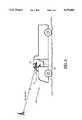
- FIG. 1is a schematic view of use of one embodiment of the invention.
- FIG. 2, 3 and 4illustrate apparatus used to determine the location of a designated object relative to a portable survey station according to three embodiments of the invention.
- FIG. 5illustrates use of a reference line or baseline defined by, or coinciding with, a line segment passing through the centers of the two SATPS antennas in FIG. 1.
- FIG. 6illustrates an alternative to the embodiment shown in FIG. 1.
- FIG. 7illustrates range determination using binocular imaging apparatus with angle readout means.
- FIG. 8illustrates an alternative to the rangefinder approach shown in FIG. 7.
- FIG. 1illustrates one embodiment of this invention, in which a vehicle 11, such as a truck or a railroad car, carries an SATPS mobile station 13.
- the mobile station 13includes first and second SATPS antennas 15 and 17, spaced apart a known distance d, that receive SATPS signals from four or more SATPS satellites 19, 21, 23 and 25. These SATPS signals are passed by the antennas 15 and 17 to an SATPS receiver/processor 27 that computes an SATPS-determined location of each of these antennas.
- the two SATPS antennas 15 and 17can be used to determine the length d and azimuthal angle ⁇ (shown in FIG. 2) for the baseline that extends between the two antennas.
- the SATPS receiver/processor 27can rapidly toggle between the two antennas 15 and 17, when necessary, and can independently compute a location for each of these antennas. When the location of each of these SATPS antennas is independently computed within a short time interval, using the same set of SATPS satellites for each determination, the (common) SATPS signal errors will be substantially identical.
- the unchanging antenna spacing dcan be used to evaluate the quality of the determination of the azimuthal angle ⁇ .
- the azimuth angle informationmay be filtered or otherwise smoothed to stabilize or otherwise improve this information for subsequent use in determination of the azimuthal angle ⁇ of the baseline relative to a selected line that intersects the baseline.
- An SATPS reference station 29, whose location is known with high accuracy,is positioned in the vicinity of the mobile station 13 and also receives SATPS signals from the SATPS satellites 19, 21, 23 and 25 through another SATPS antenna 31 that is connected to another SATPS receiver/processor 33 that (1) measures the SATPS-determined pseudorange values at the reference station 29, (2) compares these pseudorange values with the known pseudorange values for the reference station 29, and (3) computes pseudorange corrections for the reference station that are the differences between these two sets of values.
- the reference station 29has a correction signal transmitter 35 that transmits the SATPS pseudorange corrections. These pseudorange correction signals are received by a correction signal antenna that is connected to the mobile station receiver/processor 27.
- the receiver/processor 27corrects the SATPS-determined location of one or both of the SATPS antennas 15 and 17, using the pseudorange correction information received by the correction signal antenna 37, in real time, or nearly real time.
- the inaccuracies in these location coordinatescan usually be reduced to a meter or less, which is acceptable location accuracy for mapping. If surveying is being performed, other procedures can be used to reduce the location inaccuracy to a few centimeters or less.
- the mobile station 13can be separated from the reference station 29 by distances up to 500 kilometers (km). In practice, this separation distance is likely to be no more than 50 km.
- the two SATPS antennas 15 and 17are positioned at opposite ends of a baseline bar or other structure 39 of known, constant length d.
- the length dis much greater than the smallest carrier wavelength used for the SATPS signals received from the SATPS satellites 19, 21, 23 and 25.
- the SATPS signals received by the mobile station 13 at the SATPS antennas 15 and 17 and SATPS receiver/processor 27may be used for calibration or for determination of the most probable location of the first and second antennas 15 and 17.
- the location of an object 41, spaced apart from and visible from the mobile station 13,may be determined.
- the object 41is simultaneously viewed by one or two angle-measuring and range-measuring ("ARM") devices 43 and 45, such as a single radar-type gun 43 that is pointed and fired at the object, with the round trip time ⁇ t r for the return signal determining the range R from the radar-type gun to the object 41.
- ARMangle-measuring and range-measuring
- one or two coordinated optical, electro-optical or ultrasonic devices 43 and 45can be positioned adjacent to the respective antennas 15 and 17, using the known antenna separation distance d, the SATPS-determined locations of the antennas 15 and 17, and differential corrections for these antennas.
- the offset location of the object 41 relative to the mobile station 13can be determined by triangulation or other techniques.
- one set of these angles, such as the polar angles ⁇ 43 and ⁇ 45may be deleted here.
- the absolute location of the object 41can then be determined by combining the location coordinates of the mobile station 13 and the object 41.
- the SATPS reference station 29, the transmitter/antenna 35 and the receiver/antenna 37 shown in FIG. 1would be used if the SATPS location information for the antennas 15 and 17 and for the object 41 are to be processed in approximately real time. Such processing can occur at the SATPS mobile station receiver/processor 27.
- such processingcan occur at the SATPS reference station receiver/processor 33, if the transmitter 35 and the receiver 37 are exchanged so that the reference station 29 receives the raw or processed SATPS location information from the mobile station 13.
- the SATPS location informationcould be transmitted to the reference station 29 by the transmitter as this information is received from or through the SATPS receiver/processor 27.
- the survey informationcan be stored in the receiver/processor 27 and post-processed together with SATPS location information, contemporaneously measured, from a remote SATPS station such as 29.
- the receiver/processor 27would be provided with a memory of adequate size, but provision of a transmitter or receiver 37 at the mobile station 13 would be unnecessary.
- the location of an object 41 that cannot be easily approached, or that is located in a hostile environmentcan be determined without approaching the object.
- FIG. 2illustrates use of an ARM device that includes a radar-type gun 46 to determine the location of the object 41, using timed electromagnetic signal emissions with a selected frequency and sensing the time of arrival of a return signal that is reflected from the object.
- the radar gun 46measures the range R and the angle coordinates of the object 41 relative to the ARM device.
- the radar gun 46is rotatably mounted on a module 47 that measures the azimuthal angle ⁇ and the polar angle ⁇ of a vector V o (41, 46) extending from the radar gun to the object 41, relative to a selected plane PL passing through the radar gun location.
- this planemay pass through another definable point, such as a point on the Earth directly below the location of the radar gun 46, and the vertical offset of the radar gun relative to this latter point may be accounted for in the measurements.
- the azimuthal angle ⁇ and the polar angle ⁇ for each range measurement made by the radar gun 46may be sensed and stored in a memory unit that is coordinated with or forms part of the receiver/processor 27; or these angle values may be visibly displayed on one or two angle readout panels 48 and 49.
- from the radar gun 46 to the object 41is determined by the relation
- c'is the signal propagation velocity for an electromagnetic wave in the ambient medium for the frequency used by the radar gun
- ⁇ t ris the elapsed time between firing of the radar gun 46 and receipt thereat of a return signal reflected from the object 41.
- the offset Cartesian coordinates of the radar gun 46 relative to a selected point 40(FIG. 1), such as the center of the baseline connected the two SATPS antennas 15 and 17, are known to be ( ⁇ x O , ⁇ y O , ⁇ z O ) in whatever local coordinate system is used.
- the offset Cartesian coordinates of the object 41 relative to the selected reference point 40then become
- ⁇ 0is a suitable reference azimuthal angle in the plane PL in which the azimuthal angle ⁇ is measured.
- the offset computations set forth in Eqs. (2), (3) and (4)apply no matter what ARM device is used to determine the relevant angles and range.
- FIG. 3illustrates another suitable location determination apparatus 51 for determination of the aximuthal angel ⁇ and/or polar angle ⁇ of the object 41 and range R to the object relative to the mobile station 13.
- the apparatus 51includes a plane surface 53 that is approximately parallel to the local tangent plane of the Earth's surface at the mobile station site.
- the plane surface 53has a center 55, a reference line 57 preferably passing through the center 55, and a plurality of straight lines 59a, 59b, 59c, etc. radiating from the center 55 representing various azimuthal angles ⁇ relative to the reference line 57.
- the object 41(or its vertical projection 41h on the local tangent plane) is visually sighted or aligned 60i (or 60h).
- the azimuthal angle ⁇ of a horizontally oriented vector V h (41, 61) extending between the sighting guide 61 and the vertical projection 41h of the object 41 on a local tangent planeis determined and recorded, stored, displayed and/or transmitted for subsequent use.
- this anglecan be determined using a vector V o (41, 61) (or V o (41, 61') for a second alignment configuration) lying in the plane defined by a vertical sighting guide 61 (or 61') and a vector V h (41, 61) (or V h (41, 61')) and pointing directly at the object 41 or a target portion thereof.
- the polar angle ⁇can be defined as the angle between the vertical sighting guide 61 (or the vector V h (41, 61)) and the vector V o (41, 61), as illustrated.
- , from sighting guide 61 to object 41is found by standard rangefinding techniques.
- FIG. 4illustrates another suitable location determination apparatus 71 for determination of the azimuthal angle ⁇ and/or polar angle ⁇ of the object 41 and range R to the object relative to the mobile station 13 in FIG. 1.
- the apparatus 71includes a sighting tool 73 (or two adjacent sighting tools 73 and 73'), having a sighting center, that provides a view of part or all of the object 41 at a center of the sighting tool.
- the target portion of the object 41is centered in the sighting tool 73, and the azimuthal and/or polar angles corresponding to the object are read out on one or two angle display meters 75 and 77 that are part of the apparatus 71.
- the reference line 57 in FIG. 2 or 3 or 4may be taken to coincide with the direction of the baseline 39 in FIG. 1.
- the SATPS-determined location coordinates of the two SATPS antennas 15 and 17determine the reference line 57.
- the reference line 57need not pass through the designated center 55 (or sighting tool 73), if the offset distance and the offset direction between the center 55 and the reference line 57 are known.
- the offset distance d offset between the center 55 and the reference line 57, and the distances D15 and D17 from the perpendicular foot F to the respective SATPS antennas 15 and 17,may be known.
- the offset coordinates of the center 55 with respect to these two antennasbecome
- Any other suitable coordinate systemcan also be used to express the offset coordinates of the center 55 and the SATPS antennas 15 and 17.
- FIG. 1illustrates an embodiment in which the location determination means or ARM devices 43 and/or 45 are mounted on a truck bed or similar site.
- a location determination means 81can be provided within or adjacent to the cab or user-carrying portion 83 of a vehicle 85, illustrated in FIG. 6 with the vehicle door removed for clarity.
- the apparatus userwould stop the vehicle 85 and, without leaving the cab 83, would control the location determination means 81 to "sight" or obtain a visual fix on the object 41.
- the range R, the azimuthal angle ⁇ and the polar angle ⁇ (measured relative to a selected reference line 57) of a vector V o (41, 81) extending between the location determination means 81 and the object 41would be determined.
- the location determination means 81includes a binocular rangefinder 91 having two independently operable optical or ultrasound objectives 93 and 95 that are spaced apart a known distance A and that are separately operable to bring images of the object 41 from the two objectives into coincidence.
- the azimuthal angles ⁇ 93 and ⁇ 95 associated with the orientations of the objectivesare read out and used to determine the distances d(41, 93) and d(41, 95) from the respective objectives 93 and 95 to the object 41, according to the relations ##EQU1##
- ⁇is the angle between a baseline, such as L1, established by the two SATPS antennas and a selected reference line L2 in a horizontal plane.
- the angles ⁇ 93 and ⁇ 95are read out from angular measuring devices 101 and 103 that are part of the rangefinder 91.
- One concern hereis the accuracy of these angle readout values.
- the angular orientations of the two optical objectives 93 and 95may be slaved together so that the aximuthal angles ⁇ 93 and ⁇ 95 satisfy the relation
- the azimuthal angles and/or polar anglemay be read out manually and/or stored in a memory for subsequent use in relations such as Eqs. (1)-(13).
- the two mobile unit GPS antennas 15 and 17 in FIG. 1can be aligned so that the baseline 39 that extends between these antennas: (1) points directly toward the object 41; or (2) is oriented at a selected angle (e.g., 30° or 90°) relative to a horizontal line passing through the vertical projection 41h in FIG. 3.
- the rangefindercan be positioned on the baseline 39 or can be displaced from the baseline.
- FIG. 8illustrates an approach to object location that does not require determination of azimuthal or polar angles.
- a mobile SATPS station 121which may use a single SATPS antenna 123 or more than one such antenna, is sequentially positioned at locations 125A and 125B and determines the ranges R A and R B ; respectively, from a rangefinder 127 to the object 41.
- the usermight use a radar-type gun that determines range to a signal-reflecting object 41 but need not provide angle orientation information for the radar-type gun.
- triangulation using the ranges R A and R B at the respective locations 125A and 125Byields two possible locations, a correct location and a specious location, for the object 41.
- the specious locationcan be deleted by use of one additional information item, such as specification of whether the object lies generally north, generally east, generally south or generally west of one of the locations 125A or 125B.
- the mobile SATPS station 121would also communicate with a reference station, such as 29 in FIG. 1, to utilize differential SATPS corrections in determining the locations 125A and 125B with acceptable accuracy (preferably to within one meter) at the mobile station 121 or at the reference station 29.
- a Satellite Positioning Systemis a system of satellite signal transmitters, with receivers located on the Earth's surface or adjacent to the Earth's surface, that transmits information from which an observer's present location and/or the time of observation can be determined.
- Two operational systems, each of which qualifies as an SATPS,are the Global Positioning System and the Global Orbiting Navigational System.
- GPSGlobal Positioning System
- a fully operational GPSincludes up to 24 satellites approximately uniformly dispersed around six circular orbits with four satellites each, the orbits being inclined at an angle of 55° relative to the equator and being separated from each other by multiples of 60° longitude.
- the orbitshave radii of 26,560 kilometers and are approximately circular.
- the orbitsare non-geosynchoronous, with 0.5 sideral day (11.967 hours) orbital time intervals, so that the satellites move with time relative to the Earth below.
- GPS satelliteswill be visible from most points on the Earth's surface, and visual access to three or more such satellites can be used to determine an observer's position anywhere on the Earth's surface, 24 hours per day.
- Each satellitecarries cesium and/or rubidium atomic clocks to provide timing information for the signals transmitted by the satellites. Internal clock correction is provided for each satellite clock.
- the L1 signal from each satelliteis binary phase shift key (BPSK) modulated by two pseudo-random noise (PRN) codes in phase quadrature, designated as the C/A-code and P-code.
- the L2 signal from each satelliteis BPSK modulated by only the C/A-code.
- the L1 signal, modulated by the P-codecan also be used here. The nature of these PRN codes is described below.
- PRN codesallows use of a plurality of GPS satellite signals for determining an observer's position and for providing navigation information.
- a signal transmitted by a particular GPS signalis selected by generating and matching, or correlating, the PRN code for that particular satellite.
- All PRN codesare known and are generated or stored in GPS satellite signal receivers carried by ground observers.
- the C/A-code for any GPS satellitehas a length of 1023 chips or time increments before this code repeats.
- the full P-codehas a length of 259 days, with each satellite transmitting a unique portion of the full P-code.
- the portion of P-code used for a given GPS satellitehas a length of precisely one week (7.000 days) before this code portion repeats.
- the GPS satellite bit streamincludes navigational information on the ephemeris of the transmitting GPS satellite and an almanac for all GPS satellites, with parameters providing corrections for ionospheric signal propagation delays suitable for single frequency receivers and for an offset time between satellite clock time and true GPS time.
- the navigational informationis transmitted at a rate of 50 Baud.
- An SATPS antennareceives SATPS signals from a plurality (preferably four or more) of SATPS satellites and passes these signals to an SATPS signal receiver/processor, which (1) identified the SATPS satellite source for each SATPS signal, (2) determines the time at which each identified SATPS signal arrives at the antenna, and (3) determines the present location of the SATPS antenna from this information and from information on the ephemerides for each identified SATPS satellite.
- the SATPS signal antenna and signal receiver/processorare part of the user segment of a particular SATPS, the Global Positioning System, as discussed by Tom Logsdon, op. cit.
- GLONASSGlobal Orbiting Navigation Satellite System
- GLONASSGlobal Orbiting Navigation Satellite System
- GLONASSalso uses 24 satellites, distributed approximately uniformly in three orbital planes of eight satellites each. Each orbital plane has a nominal inclination of 64.8° relative to the equator, and the three orbital planes are separated from each other by multiples of 120° longitude.
- the GLONASS circular orbitshave smaller radii, about 25,510 kilometers, and a satellite period of revolution of 8/17 of a sideral day (11.26 hours).
- a GLONASS satellite and a GPS satellite and a GPS satellitewill thus complete 17 and 16 revolutions, respectively, around the Earth every 8 days.
- the L2 codeis presently modulated only by the P-code.
- the GLONASS satellitesalso transmit navigational data at at rate of 50 Baud. Because the channel frequencies are distinguishable from each other, the P-code is the same, and the C/A-code is the same, for each satellite.
- the methods for receiving and analyzing the GLONASS signalsare similar to the methods used for the GPS signals.
- Reference to a Satellite Positioning System or SATPS hereinrefers to a Global Positioning System, to a Global Orbiting Navigation Satellite System, and to any other compatible satellite-based system that provides information by which an observer's position and the time of observation can be determined, all of which meet the requirements of the present invention.
- a Satellite Positioning Systemsuch as the Global Positioning System (GPS) or the Global Orbiting Navigation Satellite System (GLONASS) uses transmission of coded radio signals, with the structure described above, from a plurality of Earth-orbiting satellites.
- GPSGlobal Positioning System
- GLONASSGlobal Orbiting Navigation Satellite System
- a single passive receiver of such signalsis capable of determining receiver absolute position in an Earth-centered, Earth-fixed coordinate reference system utilized by the SATPS.
- a configuration of two or more receiverscan be used to accurately determine the relative positions between the receivers or stations.
- This methodknown as differential positioning, is far more accurate than absolute positioning, provided that the distances between these stations are substantially less than the distances from these stations to the satellites, which is the usual case.
- Differential positioningcan be used for survey or construction work in the field, providing location coordinates and distances that are accurate to within a few centimeters.
Landscapes
- Engineering & Computer Science (AREA)
- Radar, Positioning & Navigation (AREA)
- Remote Sensing (AREA)
- Physics & Mathematics (AREA)
- General Physics & Mathematics (AREA)
- Computer Networks & Wireless Communication (AREA)
- Position Fixing By Use Of Radio Waves (AREA)
Abstract
Description
R=c'Δt.sub.r /2, (1)
Δx=Δx.sub.o +R cos (φ+φ.sub.0) cos θ,(2)
Δy=Δy.sub.o +R sin (φ+φ.sub.0) cos θ,(3)
Δz=Δz.sub.o +R sinθ, (4)
(Δx.sub.15, Δy.sub.15)=(-d.sub.offset, D.sub.15), (5)
(Δx.sub.17, Δy.sub.17)=(-d.sub.offset, D.sub.17), (6)
D.sub.15 +D.sub.17 =d. (7)
θ.sub.93 =π-φ.sub.95. (11)
d(41, 93)=d(41, 95)=(A/2) csc(φ.sub.95 -π/2), (12)
d(41, 97)=(A/2) tan (π-φ.sub.95). (13).
Claims (32)
Priority Applications (2)
| Application Number | Priority Date | Filing Date | Title |
|---|---|---|---|
| US08/115,432US5379045A (en) | 1993-09-01 | 1993-09-01 | SATPS mapping with angle orientation calibrator |
| PCT/US1994/010008WO1995006883A1 (en) | 1993-09-01 | 1994-08-31 | Satps mapping with angle orientation calibrator |
Applications Claiming Priority (1)
| Application Number | Priority Date | Filing Date | Title |
|---|---|---|---|
| US08/115,432US5379045A (en) | 1993-09-01 | 1993-09-01 | SATPS mapping with angle orientation calibrator |
Publications (1)
| Publication Number | Publication Date |
|---|---|
| US5379045Atrue US5379045A (en) | 1995-01-03 |
Family
ID=22361367
Family Applications (1)
| Application Number | Title | Priority Date | Filing Date |
|---|---|---|---|
| US08/115,432Expired - Fee RelatedUS5379045A (en) | 1993-09-01 | 1993-09-01 | SATPS mapping with angle orientation calibrator |
Country Status (2)
| Country | Link |
|---|---|
| US (1) | US5379045A (en) |
| WO (1) | WO1995006883A1 (en) |
Cited By (60)
| Publication number | Priority date | Publication date | Assignee | Title |
|---|---|---|---|---|
| US5502446A (en)* | 1994-05-02 | 1996-03-26 | Trimble Navigation Limited | GPS-based automatic target reporting and finding network and components |
| US5557284A (en)* | 1995-02-03 | 1996-09-17 | Honeywell Inc. | Spoofing detection system for a satellite positioning system |
| US5563607A (en)* | 1994-05-26 | 1996-10-08 | Trimble Navigation Limited | Time and/or location tagging of an event |
| EP0747721A1 (en)* | 1995-06-06 | 1996-12-11 | DASSAULT SERCEL Navigation-Positionnement | Method and device for precisely determining an electromagnetically shielded point by position measuring with satellites |
| US5617317A (en)* | 1995-01-24 | 1997-04-01 | Honeywell Inc. | True north heading estimator utilizing GPS output information and inertial sensor system output information |
| US5621793A (en)* | 1995-05-05 | 1997-04-15 | Rubin, Bednarek & Associates, Inc. | TV set top box using GPS |
| US5734348A (en)* | 1995-08-31 | 1998-03-31 | Nikon Corporation | Surveying system using GPS |
| DE19711357C1 (en)* | 1997-03-19 | 1998-05-14 | Thomson Csf Elektronik Gmbh Ni | Radar direction checking and adjustment method |
| US5784028A (en)* | 1996-06-27 | 1998-07-21 | Motorola, Inc. | Method and apparatus for simplex delivery of signals to obstructed geographical areas |
| US5821900A (en)* | 1996-05-27 | 1998-10-13 | Nikon Corporation | GPS survey instrument |
| US5831573A (en)* | 1996-08-23 | 1998-11-03 | Trimble Navigation Limited | Method and apparatus continously offsetting survey points by half angle calculations in real time in the field |
| US5841392A (en)* | 1995-10-02 | 1998-11-24 | Nikon Corporation | Pulse-echo ranging system with improved target |
| US5852790A (en)* | 1996-04-22 | 1998-12-22 | Westinghouse Savannah River Company | Global positioning system recorder and method government rights |
| US5872539A (en)* | 1996-05-29 | 1999-02-16 | Hughes Electronics Corporation | Method and system for providing a user with precision location information |
| US5949371A (en)* | 1998-07-27 | 1999-09-07 | Trimble Navigation Limited | Laser based reflectors for GPS positioning augmentation |
| US5952958A (en)* | 1996-04-05 | 1999-09-14 | Discovision Associates | Positioning system and method |
| US5978735A (en)* | 1996-11-05 | 1999-11-02 | Nfs Navigations-Und Flugfuhrungs-Systeme Gmbh | Satellite navigation method |
| US5983161A (en) | 1993-08-11 | 1999-11-09 | Lemelson; Jerome H. | GPS vehicle collision avoidance warning and control system and method |
| WO1999060335A1 (en)* | 1998-05-15 | 1999-11-25 | Measurement Devices Limited | Survey apparatus |
| US6021376A (en)* | 1998-07-23 | 2000-02-01 | Trimble Navigation Limited | Method of displaying connections in the field between like geographical features |
| US6052083A (en)* | 1998-03-12 | 2000-04-18 | Trimble Navigation Limited | Method and apparatus for position identification |
| US6108365A (en)* | 1995-05-05 | 2000-08-22 | Philip A. Rubin And Associates, Inc. | GPS data access system |
| US6140957A (en)* | 1998-03-12 | 2000-10-31 | Trimble Navigation Limited | Method and apparatus for navigation guidance |
| US6281970B1 (en) | 1998-03-12 | 2001-08-28 | Synergistix Llc | Airborne IR fire surveillance system providing firespot geopositioning |
| US6369755B1 (en)* | 1995-10-23 | 2002-04-09 | Trimble Navigation Limited | Integrated SATPS total survey station |
| US6401037B1 (en) | 2000-04-10 | 2002-06-04 | Trimble Navigation Limited | Integrated position and direction system for determining position of offset feature |
| US6414629B1 (en) | 2001-04-19 | 2002-07-02 | Tektrack, Llc | Tracking device |
| US6441779B1 (en)* | 1999-07-02 | 2002-08-27 | Kvh Industries, Inc. | System and method of carrier-phase attitude determination |
| US20030103001A1 (en)* | 1991-12-10 | 2003-06-05 | Huston Charles D. | Golf distance measuring system and method |
| US6594007B2 (en) | 2001-02-01 | 2003-07-15 | Snap-On Technologies, Inc. | Method and apparatus for mapping system calibration |
| US20040027278A1 (en)* | 2002-01-07 | 2004-02-12 | Samsung Electronics Co., Ltd. | Apparatus and method for locating user equipment using global positioning system and dead reckoning |
| US20060100816A1 (en)* | 2002-08-09 | 2006-05-11 | Surveylab Group Limited | Mobile instrument, viewing device, and methods of processing and storing information |
| US20070159390A1 (en)* | 2006-01-06 | 2007-07-12 | Lg Electronics Inc. | Method of providing celestial information and a mobile terminal having a function of providing the celestial information |
| US20080252517A1 (en)* | 1999-04-23 | 2008-10-16 | Fuchs Donald L | Method and apparatus for locating position of a gps device |
| US20090210098A1 (en)* | 2007-03-13 | 2009-08-20 | Nielsen Steven E | Marking apparatus and methods for creating an electronic record of marking apparatus operations |
| US20090324815A1 (en)* | 2007-03-13 | 2009-12-31 | Nielsen Steven E | Marking apparatus and marking methods using marking dispenser with machine-readable id mechanism |
| US20100026551A1 (en)* | 2003-10-06 | 2010-02-04 | Marshall University | Railroad surveying and monitoring system |
| US20100085701A1 (en)* | 2008-10-02 | 2010-04-08 | Certusview Technologies, Llc | Marking device docking stations having security features and methods of using same |
| US20100088031A1 (en)* | 2008-10-02 | 2010-04-08 | Certusview Technologies, Llc | Methods and apparatus for generating an electronic record of environmental landmarks based on marking device actuations |
| US20100188407A1 (en)* | 2008-10-02 | 2010-07-29 | Certusview Technologies, Llc | Methods and apparatus for displaying and processing facilities map information and/or other image information on a marking device |
| US20100198663A1 (en)* | 2008-10-02 | 2010-08-05 | Certusview Technologies, Llc | Methods and apparatus for overlaying electronic marking information on facilities map information and/or other image information displayed on a marking device |
| US20100245086A1 (en)* | 2008-10-02 | 2010-09-30 | Certusview Technologies, Llc | Marking apparatus configured to detect out-of-tolerance conditions in connection with underground facility marking operations, and associated methods and systems |
| US20110045175A1 (en)* | 2009-08-20 | 2011-02-24 | Certusview Technologies, Llc | Methods and marking devices with mechanisms for indicating and/or detecting marking material color |
| US20110060549A1 (en)* | 2009-08-20 | 2011-03-10 | Certusview Technologies, Llc | Methods and apparatus for assessing marking operations based on acceleration information |
| US20110117272A1 (en)* | 2009-08-20 | 2011-05-19 | Certusview Technologies, Llc | Marking device with transmitter for triangulating location during locate operations |
| WO2012024434A1 (en)* | 2010-08-17 | 2012-02-23 | Qualcomm Incorporated | Method and apparatus for rf-based ranging with multiple antennas |
| US8217836B1 (en)* | 2010-02-26 | 2012-07-10 | Rockwell Collins, Inc. | Tactical relative navigation using orientation transfer and ranging |
| CN103809190A (en)* | 2012-11-15 | 2014-05-21 | 中国科学院沈阳自动化研究所 | Satellite calibration source detection device and implementation method thereof |
| US8775077B2 (en) | 2007-03-13 | 2014-07-08 | Certusview Technologies, Llc | Systems and methods for using location data to electronically display dispensing of markers by a marking system or marking tool |
| US20140350886A1 (en)* | 2011-09-13 | 2014-11-27 | Hexagon Technology Center Gmbh | Geodetic surveying system and method with multiple target tracking functionality |
| US9004004B2 (en) | 2008-07-10 | 2015-04-14 | Certusview Technologies, Llc | Optical sensing methods and apparatus for detecting a color of a marking substance |
| US20160240910A1 (en)* | 2015-02-18 | 2016-08-18 | Commscope Technologies Llc | Antenna azimuth alignment monitor |
| US9542863B2 (en) | 2008-10-02 | 2017-01-10 | Certusview Technologies, Llc | Methods and apparatus for generating output data streams relating to underground utility marking operations |
| RU2618520C1 (en)* | 2016-04-18 | 2017-05-04 | Федеральное государственное автономное образовательное учреждение высшего образования "Сибирский федеральный университет" (СФУ) | Method for object angular orientation on radio navigation signals of spacecrafts |
| US10288738B1 (en)* | 2014-04-01 | 2019-05-14 | Rockwell Collins, Inc. | Precision mobile baseline determination device and related method |
| US10369451B2 (en) | 2012-07-05 | 2019-08-06 | Golfzondeca, Inc. | Golf GPS device with automatic hole recognition and playing hole selection |
| CN110375786A (en)* | 2019-06-27 | 2019-10-25 | 驭势科技(北京)有限公司 | A kind of scaling method, mobile unit and storage medium that sensor is joined outside |
| US10670688B2 (en)* | 2015-10-13 | 2020-06-02 | Telefonaktiebolaget Lm Ericsson (Publ) | Method and tool for reflector alignment |
| US10876835B2 (en)* | 2017-09-06 | 2020-12-29 | Howell Asset Locator, Llc | Technologies for tracking and locating underground assets |
| US12135381B2 (en) | 2021-08-31 | 2024-11-05 | James DOTAN | Precision positioning and pointing instrument |
Citations (5)
| Publication number | Priority date | Publication date | Assignee | Title |
|---|---|---|---|---|
| US4949089A (en)* | 1989-08-24 | 1990-08-14 | General Dynamics Corporation | Portable target locator system |
| US5185610A (en)* | 1990-08-20 | 1993-02-09 | Texas Instruments Incorporated | GPS system and method for deriving pointing or attitude from a single GPS receiver |
| US5194871A (en)* | 1982-03-01 | 1993-03-16 | Western Atlas International, Inc. | System for simultaneously deriving position information from a plurality of satellite transmissions |
| US5233357A (en)* | 1988-07-06 | 1993-08-03 | Wild Leitz Ag | Surveying system including an electro-optic total station and a portable receiving apparatus comprising a satellite position-measuring system |
| US5252982A (en)* | 1990-08-24 | 1993-10-12 | Leica Heerbrugg A.G. | Method of precise position determination |
Family Cites Families (4)
| Publication number | Priority date | Publication date | Assignee | Title |
|---|---|---|---|---|
| CH677154A5 (en)* | 1988-07-06 | 1991-04-15 | Wild Leitz Ag | |
| US4990922A (en)* | 1990-03-14 | 1991-02-05 | The United States Of America As Represented By The Administrator, National Aeronautics And Space Administration | System and method for measuring ocean surface currents at locations remote from land masses using synthetic aperture radar |
| SE9003500D0 (en)* | 1990-11-02 | 1990-11-02 | Geotronics Ab | HOEGHASTIGHETSMAETNING |
| JP3349510B2 (en)* | 1991-12-16 | 2002-11-25 | ピンレインジャー(オーストラリア)プロプライエタリー リミテッド | Distance measurement method |
- 1993
- 1993-09-01USUS08/115,432patent/US5379045A/ennot_activeExpired - Fee Related
- 1994
- 1994-08-31WOPCT/US1994/010008patent/WO1995006883A1/enactiveApplication Filing
Patent Citations (5)
| Publication number | Priority date | Publication date | Assignee | Title |
|---|---|---|---|---|
| US5194871A (en)* | 1982-03-01 | 1993-03-16 | Western Atlas International, Inc. | System for simultaneously deriving position information from a plurality of satellite transmissions |
| US5233357A (en)* | 1988-07-06 | 1993-08-03 | Wild Leitz Ag | Surveying system including an electro-optic total station and a portable receiving apparatus comprising a satellite position-measuring system |
| US4949089A (en)* | 1989-08-24 | 1990-08-14 | General Dynamics Corporation | Portable target locator system |
| US5185610A (en)* | 1990-08-20 | 1993-02-09 | Texas Instruments Incorporated | GPS system and method for deriving pointing or attitude from a single GPS receiver |
| US5252982A (en)* | 1990-08-24 | 1993-10-12 | Leica Heerbrugg A.G. | Method of precise position determination |
Cited By (104)
| Publication number | Priority date | Publication date | Assignee | Title |
|---|---|---|---|---|
| US20030103001A1 (en)* | 1991-12-10 | 2003-06-05 | Huston Charles D. | Golf distance measuring system and method |
| US6487500B2 (en) | 1993-08-11 | 2002-11-26 | Jerome H. Lemelson | GPS vehicle collision avoidance warning and control system and method |
| US5983161A (en) | 1993-08-11 | 1999-11-09 | Lemelson; Jerome H. | GPS vehicle collision avoidance warning and control system and method |
| US6275773B1 (en) | 1993-08-11 | 2001-08-14 | Jerome H. Lemelson | GPS vehicle collision avoidance warning and control system and method |
| US5502446A (en)* | 1994-05-02 | 1996-03-26 | Trimble Navigation Limited | GPS-based automatic target reporting and finding network and components |
| US5563607A (en)* | 1994-05-26 | 1996-10-08 | Trimble Navigation Limited | Time and/or location tagging of an event |
| US5617317A (en)* | 1995-01-24 | 1997-04-01 | Honeywell Inc. | True north heading estimator utilizing GPS output information and inertial sensor system output information |
| US5557284A (en)* | 1995-02-03 | 1996-09-17 | Honeywell Inc. | Spoofing detection system for a satellite positioning system |
| WO1997047987A1 (en)* | 1995-02-03 | 1997-12-18 | Honeywell Inc. | Spoofing detection system for a satellite positioning system |
| US6009116A (en)* | 1995-05-05 | 1999-12-28 | Philip A Rubin And Associates, Inc. | GPS TV set top box with regional restrictions |
| US5621793A (en)* | 1995-05-05 | 1997-04-15 | Rubin, Bednarek & Associates, Inc. | TV set top box using GPS |
| US6108365A (en)* | 1995-05-05 | 2000-08-22 | Philip A. Rubin And Associates, Inc. | GPS data access system |
| FR2735240A1 (en)* | 1995-06-06 | 1996-12-13 | Soc Et Rech Et Const Electroni | METHOD AND DEVICE FOR THE DETERMINATION OF A MASK POINT BY SATELLITE RADIOLOCATION. |
| US5757314A (en)* | 1995-06-06 | 1998-05-26 | Dassault Sercel Navigation-Positionnement | Method and apparatus for accurately determining the position of a masked point by satellite |
| EP0747721A1 (en)* | 1995-06-06 | 1996-12-11 | DASSAULT SERCEL Navigation-Positionnement | Method and device for precisely determining an electromagnetically shielded point by position measuring with satellites |
| US5734348A (en)* | 1995-08-31 | 1998-03-31 | Nikon Corporation | Surveying system using GPS |
| US5841392A (en)* | 1995-10-02 | 1998-11-24 | Nikon Corporation | Pulse-echo ranging system with improved target |
| US6369755B1 (en)* | 1995-10-23 | 2002-04-09 | Trimble Navigation Limited | Integrated SATPS total survey station |
| US5952958A (en)* | 1996-04-05 | 1999-09-14 | Discovision Associates | Positioning system and method |
| US5852790A (en)* | 1996-04-22 | 1998-12-22 | Westinghouse Savannah River Company | Global positioning system recorder and method government rights |
| US5821900A (en)* | 1996-05-27 | 1998-10-13 | Nikon Corporation | GPS survey instrument |
| US5872539A (en)* | 1996-05-29 | 1999-02-16 | Hughes Electronics Corporation | Method and system for providing a user with precision location information |
| US5784028A (en)* | 1996-06-27 | 1998-07-21 | Motorola, Inc. | Method and apparatus for simplex delivery of signals to obstructed geographical areas |
| US5831573A (en)* | 1996-08-23 | 1998-11-03 | Trimble Navigation Limited | Method and apparatus continously offsetting survey points by half angle calculations in real time in the field |
| US5978735A (en)* | 1996-11-05 | 1999-11-02 | Nfs Navigations-Und Flugfuhrungs-Systeme Gmbh | Satellite navigation method |
| DE19711357C1 (en)* | 1997-03-19 | 1998-05-14 | Thomson Csf Elektronik Gmbh Ni | Radar direction checking and adjustment method |
| US6480148B1 (en) | 1998-03-12 | 2002-11-12 | Trimble Navigation Ltd. | Method and apparatus for navigation guidance |
| US6052083A (en)* | 1998-03-12 | 2000-04-18 | Trimble Navigation Limited | Method and apparatus for position identification |
| US6140957A (en)* | 1998-03-12 | 2000-10-31 | Trimble Navigation Limited | Method and apparatus for navigation guidance |
| US6281970B1 (en) | 1998-03-12 | 2001-08-28 | Synergistix Llc | Airborne IR fire surveillance system providing firespot geopositioning |
| WO1999060335A1 (en)* | 1998-05-15 | 1999-11-25 | Measurement Devices Limited | Survey apparatus |
| US6021376A (en)* | 1998-07-23 | 2000-02-01 | Trimble Navigation Limited | Method of displaying connections in the field between like geographical features |
| US5949371A (en)* | 1998-07-27 | 1999-09-07 | Trimble Navigation Limited | Laser based reflectors for GPS positioning augmentation |
| US20080252517A1 (en)* | 1999-04-23 | 2008-10-16 | Fuchs Donald L | Method and apparatus for locating position of a gps device |
| US8301376B2 (en)* | 1999-04-23 | 2012-10-30 | Global Locate, Inc. | Method and apparatus for locating position of a GPS device |
| US6441779B1 (en)* | 1999-07-02 | 2002-08-27 | Kvh Industries, Inc. | System and method of carrier-phase attitude determination |
| US6401037B1 (en) | 2000-04-10 | 2002-06-04 | Trimble Navigation Limited | Integrated position and direction system for determining position of offset feature |
| US6594007B2 (en) | 2001-02-01 | 2003-07-15 | Snap-On Technologies, Inc. | Method and apparatus for mapping system calibration |
| US6414629B1 (en) | 2001-04-19 | 2002-07-02 | Tektrack, Llc | Tracking device |
| US20040027278A1 (en)* | 2002-01-07 | 2004-02-12 | Samsung Electronics Co., Ltd. | Apparatus and method for locating user equipment using global positioning system and dead reckoning |
| US7298323B2 (en)* | 2002-01-07 | 2007-11-20 | Samsung Electronics Co., Ltd. | Apparatus and method for locating user equipment using global positioning system and dead reckoning |
| US20060100816A1 (en)* | 2002-08-09 | 2006-05-11 | Surveylab Group Limited | Mobile instrument, viewing device, and methods of processing and storing information |
| US7647197B2 (en) | 2002-08-09 | 2010-01-12 | Surveylab Group Limited | Mobile instrument, viewing device, and methods of processing and storing information |
| US8180590B2 (en)* | 2003-10-06 | 2012-05-15 | Marshall University Research Corporation | Railroad surveying and monitoring system |
| US20100026551A1 (en)* | 2003-10-06 | 2010-02-04 | Marshall University | Railroad surveying and monitoring system |
| US7705774B2 (en)* | 2006-01-06 | 2010-04-27 | Lg Electronics Inc. | Method of providing celestial information and a mobile terminal having a function of providing the celestial information |
| US20070159390A1 (en)* | 2006-01-06 | 2007-07-12 | Lg Electronics Inc. | Method of providing celestial information and a mobile terminal having a function of providing the celestial information |
| US20090324815A1 (en)* | 2007-03-13 | 2009-12-31 | Nielsen Steven E | Marking apparatus and marking methods using marking dispenser with machine-readable id mechanism |
| US9086277B2 (en) | 2007-03-13 | 2015-07-21 | Certusview Technologies, Llc | Electronically controlled marking apparatus and methods |
| US8924154B2 (en) | 2007-03-13 | 2014-12-30 | Certusview Technologies, Llc | Methods, apparatus and systems for determining correctness and completeness of locate operations |
| US20090210098A1 (en)* | 2007-03-13 | 2009-08-20 | Nielsen Steven E | Marking apparatus and methods for creating an electronic record of marking apparatus operations |
| US8903643B2 (en) | 2007-03-13 | 2014-12-02 | Certusview Technologies, Llc | Hand-held marking apparatus with location tracking system and methods for logging geographic location of same |
| US8775077B2 (en) | 2007-03-13 | 2014-07-08 | Certusview Technologies, Llc | Systems and methods for using location data to electronically display dispensing of markers by a marking system or marking tool |
| US8700325B2 (en) | 2007-03-13 | 2014-04-15 | Certusview Technologies, Llc | Marking apparatus and methods for creating an electronic record of marking operations |
| US8478523B2 (en) | 2007-03-13 | 2013-07-02 | Certusview Technologies, Llc | Marking apparatus and methods for creating an electronic record of marking apparatus operations |
| US8473209B2 (en) | 2007-03-13 | 2013-06-25 | Certusview Technologies, Llc | Marking apparatus and marking methods using marking dispenser with machine-readable ID mechanism |
| US20090208642A1 (en)* | 2007-03-13 | 2009-08-20 | Nielsen Steven E | Marking apparatus and methods for creating an electronic record of marking operations |
| US9004004B2 (en) | 2008-07-10 | 2015-04-14 | Certusview Technologies, Llc | Optical sensing methods and apparatus for detecting a color of a marking substance |
| US20100198663A1 (en)* | 2008-10-02 | 2010-08-05 | Certusview Technologies, Llc | Methods and apparatus for overlaying electronic marking information on facilities map information and/or other image information displayed on a marking device |
| US8770140B2 (en) | 2008-10-02 | 2014-07-08 | Certusview Technologies, Llc | Marking apparatus having environmental sensors and operations sensors for underground facility marking operations, and associated methods and systems |
| US9542863B2 (en) | 2008-10-02 | 2017-01-10 | Certusview Technologies, Llc | Methods and apparatus for generating output data streams relating to underground utility marking operations |
| US9177403B2 (en) | 2008-10-02 | 2015-11-03 | Certusview Technologies, Llc | Methods and apparatus for overlaying electronic marking information on facilities map information and/or other image information displayed on a marking device |
| US20100085701A1 (en)* | 2008-10-02 | 2010-04-08 | Certusview Technologies, Llc | Marking device docking stations having security features and methods of using same |
| US20100263591A1 (en)* | 2008-10-02 | 2010-10-21 | Certusview Technologies, Llc | Marking apparatus having environmental sensors and operations sensors for underground facility marking operations, and associated methods and systems |
| US20100085694A1 (en)* | 2008-10-02 | 2010-04-08 | Certusview Technologies, Llc | Marking device docking stations and methods of using same |
| US20100262470A1 (en)* | 2008-10-02 | 2010-10-14 | Certusview Technologies, Llc | Methods, apparatus, and systems for analyzing use of a marking device by a technician to perform an underground facility marking operation |
| US8467969B2 (en) | 2008-10-02 | 2013-06-18 | Certusview Technologies, Llc | Marking apparatus having operational sensors for underground facility marking operations, and associated methods and systems |
| US20100256825A1 (en)* | 2008-10-02 | 2010-10-07 | Certusview Technologies, Llc | Marking apparatus for receiving environmental information regarding underground facility marking operations, and associated methods and systems |
| US20100255182A1 (en)* | 2008-10-02 | 2010-10-07 | Certusview Technologies, Llc | Marking apparatus having operational sensors for underground facility marking operations, and associated methods and systems |
| US8478525B2 (en) | 2008-10-02 | 2013-07-02 | Certusview Technologies, Llc | Methods, apparatus, and systems for analyzing use of a marking device by a technician to perform an underground facility marking operation |
| US8478524B2 (en) | 2008-10-02 | 2013-07-02 | Certusview Technologies, Llc | Methods and apparatus for dispensing marking material in connection with underground facility marking operations based on environmental information and/or operational information |
| US8583264B2 (en) | 2008-10-02 | 2013-11-12 | Certusview Technologies, Llc | Marking device docking stations and methods of using same |
| US8589202B2 (en) | 2008-10-02 | 2013-11-19 | Certusview Technologies, Llc | Methods and apparatus for displaying and processing facilities map information and/or other image information on a marking device |
| US8600526B2 (en) | 2008-10-02 | 2013-12-03 | Certusview Technologies, Llc | Marking device docking stations having mechanical docking and methods of using same |
| US8612148B2 (en) | 2008-10-02 | 2013-12-17 | Certusview Technologies, Llc | Marking apparatus configured to detect out-of-tolerance conditions in connection with underground facility marking operations, and associated methods and systems |
| US8965700B2 (en) | 2008-10-02 | 2015-02-24 | Certusview Technologies, Llc | Methods and apparatus for generating an electronic record of environmental landmarks based on marking device actuations |
| US20100088031A1 (en)* | 2008-10-02 | 2010-04-08 | Certusview Technologies, Llc | Methods and apparatus for generating an electronic record of environmental landmarks based on marking device actuations |
| US8644965B2 (en) | 2008-10-02 | 2014-02-04 | Certusview Technologies, Llc | Marking device docking stations having security features and methods of using same |
| US20100247754A1 (en)* | 2008-10-02 | 2010-09-30 | Certusview Technologies, Llc | Methods and apparatus for dispensing marking material in connection with underground facility marking operations based on environmental information and/or operational information |
| US8731830B2 (en) | 2008-10-02 | 2014-05-20 | Certusview Technologies, Llc | Marking apparatus for receiving environmental information regarding underground facility marking operations, and associated methods and systems |
| US20100188407A1 (en)* | 2008-10-02 | 2010-07-29 | Certusview Technologies, Llc | Methods and apparatus for displaying and processing facilities map information and/or other image information on a marking device |
| US20100245086A1 (en)* | 2008-10-02 | 2010-09-30 | Certusview Technologies, Llc | Marking apparatus configured to detect out-of-tolerance conditions in connection with underground facility marking operations, and associated methods and systems |
| US9097522B2 (en) | 2009-08-20 | 2015-08-04 | Certusview Technologies, Llc | Methods and marking devices with mechanisms for indicating and/or detecting marking material color |
| US20110060549A1 (en)* | 2009-08-20 | 2011-03-10 | Certusview Technologies, Llc | Methods and apparatus for assessing marking operations based on acceleration information |
| US20110117272A1 (en)* | 2009-08-20 | 2011-05-19 | Certusview Technologies, Llc | Marking device with transmitter for triangulating location during locate operations |
| US8620572B2 (en)* | 2009-08-20 | 2013-12-31 | Certusview Technologies, Llc | Marking device with transmitter for triangulating location during locate operations |
| US8620616B2 (en) | 2009-08-20 | 2013-12-31 | Certusview Technologies, Llc | Methods and apparatus for assessing marking operations based on acceleration information |
| US20110045175A1 (en)* | 2009-08-20 | 2011-02-24 | Certusview Technologies, Llc | Methods and marking devices with mechanisms for indicating and/or detecting marking material color |
| US8217836B1 (en)* | 2010-02-26 | 2012-07-10 | Rockwell Collins, Inc. | Tactical relative navigation using orientation transfer and ranging |
| WO2012024434A1 (en)* | 2010-08-17 | 2012-02-23 | Qualcomm Incorporated | Method and apparatus for rf-based ranging with multiple antennas |
| US20140350886A1 (en)* | 2011-09-13 | 2014-11-27 | Hexagon Technology Center Gmbh | Geodetic surveying system and method with multiple target tracking functionality |
| US10240924B2 (en)* | 2011-09-13 | 2019-03-26 | Hexagon Technology Center Gmbh | Geodetic surveying system and method with multiple target tracking functionality |
| US10369451B2 (en) | 2012-07-05 | 2019-08-06 | Golfzondeca, Inc. | Golf GPS device with automatic hole recognition and playing hole selection |
| US11590403B2 (en) | 2012-07-05 | 2023-02-28 | GolfzonDeca Inc. | Golf GPS device with hole recognition and hole selection |
| US11045708B2 (en) | 2012-07-05 | 2021-06-29 | Golfzondeca, Inc. | Golf GPS device with hole recognition and hole selection |
| CN103809190A (en)* | 2012-11-15 | 2014-05-21 | 中国科学院沈阳自动化研究所 | Satellite calibration source detection device and implementation method thereof |
| US10288738B1 (en)* | 2014-04-01 | 2019-05-14 | Rockwell Collins, Inc. | Precision mobile baseline determination device and related method |
| US20160240910A1 (en)* | 2015-02-18 | 2016-08-18 | Commscope Technologies Llc | Antenna azimuth alignment monitor |
| US10670688B2 (en)* | 2015-10-13 | 2020-06-02 | Telefonaktiebolaget Lm Ericsson (Publ) | Method and tool for reflector alignment |
| RU2618520C1 (en)* | 2016-04-18 | 2017-05-04 | Федеральное государственное автономное образовательное учреждение высшего образования "Сибирский федеральный университет" (СФУ) | Method for object angular orientation on radio navigation signals of spacecrafts |
| US10876835B2 (en)* | 2017-09-06 | 2020-12-29 | Howell Asset Locator, Llc | Technologies for tracking and locating underground assets |
| CN110375786A (en)* | 2019-06-27 | 2019-10-25 | 驭势科技(北京)有限公司 | A kind of scaling method, mobile unit and storage medium that sensor is joined outside |
| CN110375786B (en)* | 2019-06-27 | 2021-07-02 | 驭势科技(北京)有限公司 | Calibration method of sensor external parameter, vehicle-mounted equipment and storage medium |
| US12135381B2 (en) | 2021-08-31 | 2024-11-05 | James DOTAN | Precision positioning and pointing instrument |
Also Published As
| Publication number | Publication date |
|---|---|
| WO1995006883A1 (en) | 1995-03-09 |
Similar Documents
| Publication | Publication Date | Title |
|---|---|---|
| US5379045A (en) | SATPS mapping with angle orientation calibrator | |
| US5739785A (en) | Location and generation of high accuracy survey control marks using satellites | |
| US5568152A (en) | Integrated image transfer for remote target location | |
| US6369755B1 (en) | Integrated SATPS total survey station | |
| US5471218A (en) | Integrated terrestrial survey and satellite positioning system | |
| US6727849B1 (en) | Seamless surveying system | |
| US6052083A (en) | Method and apparatus for position identification | |
| US5949371A (en) | Laser based reflectors for GPS positioning augmentation | |
| US6732051B1 (en) | Seamless surveying system | |
| US5614913A (en) | Optimization of survey coordinate transformations | |
| US6140957A (en) | Method and apparatus for navigation guidance | |
| US5815118A (en) | Rubber sheeting of a map | |
| US8705022B2 (en) | Navigation system using both GPS and laser reference | |
| US6677938B1 (en) | Generating positional reality using RTK integrated with scanning lasers | |
| EP1774257B1 (en) | Combination laser system and global navigation satellite system | |
| US7978128B2 (en) | Land survey system | |
| WO2007000067A1 (en) | Method and system for acquiring azimuth information using signals provided by satellites | |
| KR20180072914A (en) | Positioning system for gpr data using geographic information system and road surface image | |
| US5835069A (en) | GPS antennas and receivers configured as handles for a surveyor's optical total station | |
| US6259403B1 (en) | GPS positioning utilizing laser based reflectors augmentation | |
| Nebot | Sensors used for autonomous navigation | |
| US6104339A (en) | All-terrain error correction | |
| JP2911363B2 (en) | High-accuracy high-speed surveying method and device using satellite | |
| Golubev | Surveying | |
| Mourad | New techniques for geodetic measurements at sea |
Legal Events
| Date | Code | Title | Description |
|---|---|---|---|
| FEPP | Fee payment procedure | Free format text:PAYOR NUMBER ASSIGNED (ORIGINAL EVENT CODE: ASPN); ENTITY STATUS OF PATENT OWNER: LARGE ENTITY | |
| FPAY | Fee payment | Year of fee payment:4 | |
| AS | Assignment | Owner name:ABN AMRO BANK N.V., AS AGENT, ILLINOIS Free format text:SECURITY AGREEMENT;ASSIGNOR:TRIMBLE NAVIGATION LIMITED;REEL/FRAME:010996/0643 Effective date:20000714 | |
| REMI | Maintenance fee reminder mailed | ||
| FPAY | Fee payment | Year of fee payment:8 | |
| SULP | Surcharge for late payment | Year of fee payment:7 | |
| AS | Assignment | Owner name:TRIMBLE NAVIGATION LIMITED, CALIFORNIA Free format text:RELEASE OF SECURITY INTEREST;ASSIGNOR:ABN AMRO BANK N.V.;REEL/FRAME:016345/0177 Effective date:20050620 | |
| REMI | Maintenance fee reminder mailed | ||
| LAPS | Lapse for failure to pay maintenance fees | ||
| LAPS | Lapse for failure to pay maintenance fees | Free format text:PATENT EXPIRED FOR FAILURE TO PAY MAINTENANCE FEES (ORIGINAL EVENT CODE: EXP.); ENTITY STATUS OF PATENT OWNER: LARGE ENTITY | |
| STCH | Information on status: patent discontinuation | Free format text:PATENT EXPIRED DUE TO NONPAYMENT OF MAINTENANCE FEES UNDER 37 CFR 1.362 | |
| FP | Lapsed due to failure to pay maintenance fee | Effective date:20070103 |