US5378879A - Induction heating of loaded materials - Google Patents
Induction heating of loaded materialsDownload PDFInfo
- Publication number
- US5378879A US5378879AUS08/049,900US4990093AUS5378879AUS 5378879 AUS5378879 AUS 5378879AUS 4990093 AUS4990093 AUS 4990093AUS 5378879 AUS5378879 AUS 5378879A
- Authority
- US
- United States
- Prior art keywords
- article
- particles
- particle
- host material
- heat
- Prior art date
- Legal status (The legal status is an assumption and is not a legal conclusion. Google has not performed a legal analysis and makes no representation as to the accuracy of the status listed.)
- Expired - Lifetime
Links
Images
Classifications
- H—ELECTRICITY
- H05—ELECTRIC TECHNIQUES NOT OTHERWISE PROVIDED FOR
- H05B—ELECTRIC HEATING; ELECTRIC LIGHT SOURCES NOT OTHERWISE PROVIDED FOR; CIRCUIT ARRANGEMENTS FOR ELECTRIC LIGHT SOURCES, IN GENERAL
- H05B6/00—Heating by electric, magnetic or electromagnetic fields
- H05B6/02—Induction heating
- H—ELECTRICITY
- H01—ELECTRIC ELEMENTS
- H01R—ELECTRICALLY-CONDUCTIVE CONNECTIONS; STRUCTURAL ASSOCIATIONS OF A PLURALITY OF MUTUALLY-INSULATED ELECTRICAL CONNECTING ELEMENTS; COUPLING DEVICES; CURRENT COLLECTORS
- H01R43/00—Apparatus or processes specially adapted for manufacturing, assembling, maintaining, or repairing of line connectors or current collectors or for joining electric conductors
- H01R43/02—Apparatus or processes specially adapted for manufacturing, assembling, maintaining, or repairing of line connectors or current collectors or for joining electric conductors for soldered or welded connections
- H01R43/0242—Apparatus or processes specially adapted for manufacturing, assembling, maintaining, or repairing of line connectors or current collectors or for joining electric conductors for soldered or welded connections comprising means for controlling the temperature, e.g. making use of the curie point
- B—PERFORMING OPERATIONS; TRANSPORTING
- B29—WORKING OF PLASTICS; WORKING OF SUBSTANCES IN A PLASTIC STATE IN GENERAL
- B29C—SHAPING OR JOINING OF PLASTICS; SHAPING OF MATERIAL IN A PLASTIC STATE, NOT OTHERWISE PROVIDED FOR; AFTER-TREATMENT OF THE SHAPED PRODUCTS, e.g. REPAIRING
- B29C35/00—Heating, cooling or curing, e.g. crosslinking or vulcanising; Apparatus therefor
- B29C35/02—Heating or curing, e.g. crosslinking or vulcanizing during moulding, e.g. in a mould
- B29C35/08—Heating or curing, e.g. crosslinking or vulcanizing during moulding, e.g. in a mould by wave energy or particle radiation
- B—PERFORMING OPERATIONS; TRANSPORTING
- B29—WORKING OF PLASTICS; WORKING OF SUBSTANCES IN A PLASTIC STATE IN GENERAL
- B29C—SHAPING OR JOINING OF PLASTICS; SHAPING OF MATERIAL IN A PLASTIC STATE, NOT OTHERWISE PROVIDED FOR; AFTER-TREATMENT OF THE SHAPED PRODUCTS, e.g. REPAIRING
- B29C70/00—Shaping composites, i.e. plastics material comprising reinforcements, fillers or preformed parts, e.g. inserts
- B29C70/58—Shaping composites, i.e. plastics material comprising reinforcements, fillers or preformed parts, e.g. inserts comprising fillers only, e.g. particles, powder, beads, flakes, spheres
- H—ELECTRICITY
- H01—ELECTRIC ELEMENTS
- H01R—ELECTRICALLY-CONDUCTIVE CONNECTIONS; STRUCTURAL ASSOCIATIONS OF A PLURALITY OF MUTUALLY-INSULATED ELECTRICAL CONNECTING ELEMENTS; COUPLING DEVICES; CURRENT COLLECTORS
- H01R4/00—Electrically-conductive connections between two or more conductive members in direct contact, i.e. touching one another; Means for effecting or maintaining such contact; Electrically-conductive connections having two or more spaced connecting locations for conductors and using contact members penetrating insulation
- H01R4/70—Insulation of connections
- H01R4/72—Insulation of connections using a heat shrinking insulating sleeve
- H—ELECTRICITY
- H05—ELECTRIC TECHNIQUES NOT OTHERWISE PROVIDED FOR
- H05B—ELECTRIC HEATING; ELECTRIC LIGHT SOURCES NOT OTHERWISE PROVIDED FOR; CIRCUIT ARRANGEMENTS FOR ELECTRIC LIGHT SOURCES, IN GENERAL
- H05B6/00—Heating by electric, magnetic or electromagnetic fields
- H05B6/02—Induction heating
- H05B6/10—Induction heating apparatus, other than furnaces, for specific applications
- H05B6/105—Induction heating apparatus, other than furnaces, for specific applications using a susceptor
- H05B6/106—Induction heating apparatus, other than furnaces, for specific applications using a susceptor in the form of fillings
- B—PERFORMING OPERATIONS; TRANSPORTING
- B29—WORKING OF PLASTICS; WORKING OF SUBSTANCES IN A PLASTIC STATE IN GENERAL
- B29C—SHAPING OR JOINING OF PLASTICS; SHAPING OF MATERIAL IN A PLASTIC STATE, NOT OTHERWISE PROVIDED FOR; AFTER-TREATMENT OF THE SHAPED PRODUCTS, e.g. REPAIRING
- B29C35/00—Heating, cooling or curing, e.g. crosslinking or vulcanising; Apparatus therefor
- B29C35/02—Heating or curing, e.g. crosslinking or vulcanizing during moulding, e.g. in a mould
- B29C35/08—Heating or curing, e.g. crosslinking or vulcanizing during moulding, e.g. in a mould by wave energy or particle radiation
- B29C35/0805—Heating or curing, e.g. crosslinking or vulcanizing during moulding, e.g. in a mould by wave energy or particle radiation using electromagnetic radiation
- B29C2035/0811—Heating or curing, e.g. crosslinking or vulcanizing during moulding, e.g. in a mould by wave energy or particle radiation using electromagnetic radiation using induction
- B29C2035/0816—Heating or curing, e.g. crosslinking or vulcanizing during moulding, e.g. in a mould by wave energy or particle radiation using electromagnetic radiation using induction using eddy currents
- B—PERFORMING OPERATIONS; TRANSPORTING
- B29—WORKING OF PLASTICS; WORKING OF SUBSTANCES IN A PLASTIC STATE IN GENERAL
- B29K—INDEXING SCHEME ASSOCIATED WITH SUBCLASSES B29B, B29C OR B29D, RELATING TO MOULDING MATERIALS OR TO MATERIALS FOR MOULDS, REINFORCEMENTS, FILLERS OR PREFORMED PARTS, e.g. INSERTS
- B29K2705/00—Use of metals, their alloys or their compounds, for preformed parts, e.g. for inserts
- B29K2705/02—Aluminium
- B—PERFORMING OPERATIONS; TRANSPORTING
- B29—WORKING OF PLASTICS; WORKING OF SUBSTANCES IN A PLASTIC STATE IN GENERAL
- B29K—INDEXING SCHEME ASSOCIATED WITH SUBCLASSES B29B, B29C OR B29D, RELATING TO MOULDING MATERIALS OR TO MATERIALS FOR MOULDS, REINFORCEMENTS, FILLERS OR PREFORMED PARTS, e.g. INSERTS
- B29K2705/00—Use of metals, their alloys or their compounds, for preformed parts, e.g. for inserts
- B29K2705/08—Transition metals
Definitions
- This inventionrelates to high frequency magnetic induction heating of materials.
- heatis employed to recover polymeric heat recoverable articles such as heat shrink tubing and molded parts, cure gels, melt or cure adhesives, activate foaming agents, dry inks, cure ceramics, initiate polymerization, initiate or speed up catalytic reactions, or heat treat parts among other applications.
- polymeric heat recoverable articlessuch as heat shrink tubing and molded parts, cure gels, melt or cure adhesives, activate foaming agents, dry inks, cure ceramics, initiate polymerization, initiate or speed up catalytic reactions, or heat treat parts among other applications.
- the speed at which the material is heatedis a significant consideration in the efficiency and effectiveness of the overall process.
- ultraviolet, infrared, hot air, hot liquid, and flame heating methods, or other examples where external heat sources are usedit is often difficult to obtain uniform heat distribution in the material through to its center.
- the center of the materialIn instances where the center of the material is not adequately heated, its transition from the initial state may not fully or uniformly occur.
- excessive heatmay be required to be applied at the surface whereby such excessive temperature conditions can lead to degradation of the material surface.
- the extended time required to apply heat to accomplish the transition to the desired statediminishes the cost-effectiveness of the system.
- thermally conductive fillersare used in the material to improve the heat transfer from the surface of the material to its center, large amounts of filler that may adversely affect the properties of the host material are necessary for a smooth temperature gradient.
- electromagnetic heating techniquessuch as microwave, dielectric and magnetic induction, all provide internal heating of non-conductive articles, such as polymeric heat recoverable articles, gels, adhesives, foams, inks and ceramics.
- the electromagnetic energyis indirectly coupled to the material and heat is generated uniformly within the bulk of the material.
- microwave and dielectric heating techniquesare based primarily on the heat generated in the dielectric material by the "rattling" of electric dipoles as they try to align with a rapidly alternating applied electric field.
- Microwave heatingrequires exposure to fields at frequencies in the high Megahertz or Gigahertz range where water dipoles resonate. The presence of water on the surface of a dielectric material to be heated with microwaves may result in non-uniform heating of the material.
- Dielectric heatingemploys frequencies from about 27 MHz to high Megahertz where the electric dipoles of most dielectrics resonate. The dielectric material being heated in this fashion does not have an inherent temperature control; the oscillating electric dipoles continue to generate heat, thereby causing degradation of the material when the heating is excessive.
- Magnetic induction heatingemploys alternating magnetic fields such as those produced in an induction coil to couple with a work piece situated inside the coil.
- a magnetic or electrically conductive materialcan couple with the applied field and thereby transform the coupled electromagnetic energy into thermal energy.
- a non-magnetic and electrically non-conductive materialis transparent to the magnetic field and therefore cannot couple with the field to generate heat.
- such a materialmay be heated by magnetic induction heating by uniformly distributing ferromagnetic particles within the material and exposing the article to an alternating high frequency electromagnetic field. Small sized ferromagnetic particles are efficient heat generators when exposed to alternating fields of frequency from about 100 kHz to about 50 MHz.
- Materials suitable for induction heatinginclude ferromagnetic and ferromagnetic materials.
- ferromagnetic and ferrimagnetic materialsIn this application, we use the definition of ferromagnetic and ferrimagnetic materials as set forth in a publication by R. M. Bozorth entitled “Ferromagnetism”, Bell Telephone Laboratories, Inc. D. Van Nostrand Company, Inc., 1951, which is hereby incorporated by reference for all purposes.
- Ferrimagnetic materials, or ferritesare a subgroup of ferromagnetic materials. A detailed analysis of ferrimagnetism is set forth by Smit and Wijn in "Ferrites", John Wiley & Son. 1959, which is hereby incorporated by reference for all purposes.
- Ferrimagnetic materialsusually exhibit very low electrical conductivity compared to ferromagnetic metals and metal alloys.
- Ferromagnetic materialssuch as iron, nickel, cobalt, iron alloys, nickel alloys, cobalt alloys, permalloy, and several steels, and ferrimagnetic materials such as magnetite, nickel-zinc ferrite, manganese-zinc ferrite, and copper-zinc ferrite are all suitable as heat generating particles dispersed in a non-magnetic, electrically non-conductive host material exposed to a high frequency alternating magnetic field.
- electrically conductive, non-magnetic metalssuch as copper, aluminum and brass may be used in the form of particles to produce heat, they are less efficient than magnetic materials and are therefore not preferred.
- Ferromagnetic materialsgenerate heat primarily due to combination of induced eddy currents and magnetic hysteresis losses.
- ⁇is the electrical conductivity of the particle in ohm -1 -m -1
- ⁇is the angular frequency of the applied field in sec -1
- ⁇ ris the magnetic permeability of the particle relative to air.
- This distance ⁇is defined as the particle "skin depth" when the particle is exposed to an alternating magnetic field.
- the current densityhas dropped to 1/e, or about 37% of its value at the surface. Therefore, a particle comprising a ferromagnetic material of electrical conductivity ⁇ and relative magnetic permeability ⁇ r exposed to an alternating electromagnetic field of frequency ⁇ , has a skin depth defined by the above equation.
- Electrically conductive ferromagnetic particles of a size several times larger than the particle skin depthmay be efficient generators of heat from eddy currents.
- Small skin depthmay be achieved with particles of high magnetic permeability and high electrical conductivity exposed to a magnetic field of high frequency.
- about 37% of the induced current densitywill be confined in a region of the particle 6.2 ⁇ m from the surface of the particle.
- the magnitude of the induced current densityincreases with the size of the eddy current loop and hence with the size of the particle.
- Eddy current lossesare negligible in electrically less conductive particles due to the large skin depth of such particles.
- a manganese-zinc ferritesuch as ferrite Mn-67 from Ceramic Magnetics, with an electrical conductivity of 0.67 l ohm -1 -m -1 , and a relative magnetic permeability of 4000 exposed to a field of frequency 5 MHz has a skin depth of 435 ⁇ m and particles greater than about a millimeter are necessary for the generation of eddy current losses.
- Such large particleswill adversely alter the properties of the host material and are, hence, undesirable.
- an electrically non-conductive nickel-zinc ferritesuch as CMD 5005 from Ceramic Magnetics, with an electrical conductivity of 1.0 ⁇ 10 -7 ohm -1 -m -1 , a relative permeability of 3000 exposed to a field of frequency 5 MHz has a skin depth of 1.3 ⁇ 10 7 ⁇ m or 13 m.
- Electrode non-conductive ferrimagnetic particlessuch as ferrite particles, or electrically conductive ferromagnetic particles that have all three dimensions smaller than the skin depth heat up primarily due to magnetic hysteresis losses.
- the magnetic dipoles within each magnetic domain of the particletend to align with the rapidly alternating magnetic field thereby resulting in domain wall movement. If the alignment of the dipoles is not in phase with the field, the alignment lags the field and follows a hysteresis loop.
- the hysteresis looprepresents the response of the ferromagnetic material to an applied magnetic field and its size and shape depend on the properties of the ferromagnetic material and on the strength of the applied field.
- the area enclosed by the hysteresis looprepresents the work required to take the material through the hysteresis cycle. When this cycle is repeated, dissipative processes within the material due to realignment of the magnetic domains result in a transformation of the magnetic energy into internal thermal energy which raises the temperature of the material. Hysteresis losses do not depend on the particle size as long as the particle size is equal to at least one magnetic domain.
- the amount of heat generated by particles dispersed in an electrically non-conductive, non-magnetic host materialdepends on several parameters including the following equipment and particle parameters:
- Particles of the present inventionare highly efficient in that they provide fast heating at low particle volume fractions in the host material, thereby having no adverse effect on the host material properties.
- the Curie temperaturea critical temperature
- Curie pointa critical temperature
- its magnetic permeabilitydrops precipitously to a value approaching 1.
- the particlethen loses much of its ability to respond to a magnetic field and heating is significantly diminished.
- the temperature of the particledrops below the Curie point, the particle regains its magnetic properties and heating resumes. Therefore, when the temperature of the particle is less than the Curie point, the particle heats.
- the temperature of the particleis greater than the Curie point, the particle essentially stops increasing in temperature. Therefore, the particle autoregulates.
- the Curie pointis a practical autoregulation means for preventing the host material from being overheated.
- Uniform dispersion of the particles throughout the bulk of the materialfacilitates uniform heating.
- induction heatingalso allows selective and controlled heating. Selective heating can result where the particles are placed in higher concentrations in areas to be heated to a relatively greater extent.
- the temperature of articles loaded with ferromagnetic particles and heated by induction heatingmay be controlled by utilization of particles having a Curie point near the desired temperature.
- induction heatingWith induction heating, it is possible to heat an electrically non-conductive material in situ quickly, uniformly, selectively and in a controlled fashion.
- Particles for induction heatingare added to the electrically non-conductive, non-magnetic host material and exposed to high frequency alternating electromagnetic fields such as those produced in an induction coil. Selection of the particles according to the present invention results in faster, more uniform and more controlled heating.
- These particlesadvantageously have the configuration of a flake, i.e., a thin disk-like configuration. Heat-generating efficiency of these particles permits a smaller percentage volume of particles in the host material such that the desired properties of the host material, remain essentially unchanged. Additionally, temperature regulation is possible to prevent overheating of the host material.
- the inventionprovides a heat generating article, for use in an alternating magnetic field, such as that produced by an induction coil, said article comprising a non-magnetic, electrically non-conductive host material in which particles are dispersed, said particles comprising ferromagnetic material having both high magnetic permeability and high electrical conductivity, said particles having a skin depth and a configuration including first, second and third orthogonal dimensions, wherein;
- said first and second orthogonal dimensionsare greater than the skin depth of the particle
- said first and second orthogonal dimensionsare at least 5 times said third orthogonal dimension.
- the first and second orthogonal dimensions of the particlewhich are the larger of the dimensions, are each preferably between about 1 ⁇ m and about 300 ⁇ m.
- the ferromagnetic materialcomprises a metal or metal alloy.
- the preferred ferromagnetic materialinclude nickel or nickel alloys, such as a nickel aluminum alloy.
- the configuration of the nickel particlespreferably comprises a nickel flake.
- the percentage of particles interspersed in the host materialis preferably between about 0.1% and about 50% by volume, more preferably between about 0.5% and about 10%, and especially less than about 5% by volume, such that the properties of the host materials are essentially unchanged.
- the host materialis electrically non-conductive and non-magnetic, such as a polymer or a ceramic.
- the ferromagnetic particleshave an electrical conductivity of greater than about 10 6 ohm -1 m -1 .
- the preferred initial magnetic permeability of the particles relative to airis greater than about 70.
- the ferromagnetic materialhas a Curie temperature at least about equal to the temperature to which said article is to be heated.
- the particlemay be comprised of a homogeneous material, or may be comprised of a central carrier portion and a coating.
- the carrier materialmay be any of a number of magnetic or non-magnetic materials. Additionally, the carrier material may be any of a number of electrically conductive or non-conductive materials.
- the coatingis preferably of a highly magnetic, highly electrically conductive material, such as the ferromagnetic materials described above. Alternatively, when the central carrier portion comprises a highly magnetic, highly electrically non-conductive material and generates heat, the coating may be non-magnetic and/or electrically non-conductive, such as an oxide layer to prevent oxidation of the central carrier portion, or a coupling agent to aid admixing of the particles with the host material.
- the articlemay undergo a change in shape, volume, or viscosity upon heating.
- the articlemay be a heat recoverable article, a foam, an adhesive or a gel.
- the Curie temperature of the ferromagnetic materialwill be equal to at least about the temperature at which the materials is to be heated.
- the host materialmay also be a fusible material having a melt temperature T m . In this case, the Curie temperature is preferably at least about the melt temperature of the host material.
- the articlemay be oriented such that an axis parallel to the greatest dimension of the article is disposed generally parallel with respect to the magnetic field lines generated by the coil.
- the inventionprovides an arrangement for forming a block in an optic or electric cable against transmission of fluid along the cable comprising:
- a heat activatable blocking constructionpositioned in proximity to the wires of the cable, said blocking construction comprising a host material in which particles are dispersed, said particles comprising ferromagnetic material having high magnetic permeability and high electrical conductivity, said particles having a skin depth and a configuration including first, second and third orthogonal dimensions, wherein said first and second orthogonal dimensions are greater than the skin depth of the particle and said first and second orthogonal dimensions are at least about 5 times said third orthogonal dimension; and
- the blocking constructionmay include a plurality of openings for receiving the wires.
- the covermay comprise a host material in which ferromagnetic particles are dispersed, said particles comprising ferromagnetic material having high magnetic permeability and high electrical conductivity, said particles having a skin depth and a configuration including first, second and third orthogonal dimensions, wherein said first and second orthogonal dimensions are greater than the skin depth of the particle and wherein said first and second orthogonal dimensions are at least 5 times said third orthogonal dimension.
- the covermay advantageously comprise an inner layer and an outer, preferably heat recoverable, layer.
- the inner layercomprises a host material in which ferromagnetic particles are dispersed, said particles comprising ferromagnetic material having high magnetic permeability and high electrical conductivity, said particles having a skin depth and a configuration including first, second and third orthogonal dimensions, wherein said first and second orthogonal dimensions are greater than the skin depth of the particle and wherein said first and second orthogonal dimensions are at least 5 times said third orthogonal dimension.
- the host materialmay advantageously comprise a fusible polymeric sealant or adhesive.
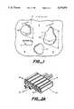
- FIG. 1is a cross-sectional view of flake particles interspersed within a host material.
- FIG. 2Ais a perspective view of an arrangement for forming a fluid block.
- FIG. 2Bis a cross-sectional view of the embodiment of FIG. 2A after installation.
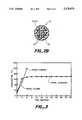
- FIG. 3is a Temperature-Time curve illustrating the effect of temperature regulation.
- the present inventioncomprises an article for use in high frequency alternating magnetic fields where heat is generated to thereby transform the article to a different state or configuration.
- the articlecomprises a host material including ferromagnetic particles dispersed therein.
- the host materialis electrically non-conductive, and non-magnetic and may be a polymeric heat recoverable article, a gel, an adhesive, a foam, an ink or a ceramic.
- the articleis heated to transform the article from its initial state to a new condition.
- induction heatis produced internally by subjecting the article to alternating magnetic fields at high frequencies between about 100 kHz and about 50 MHz and preferably between about 450 kHz and about 10 MHz. Selection of particles to be interspersed in the host material is the key to providing an efficient, autoregulating heating article that heats quickly, internally, uniformly and selectively.
- a primary object of the present inventionis to provide particles which are particularly fast heating in comparison to the prior art.
- the prior arthas utilized large sized metallic spheres or fibers for induction heating.
- the shape of small ferromagnetic particlesis normally somewhat irregular. Nevertheless, for purposes of the present invention, their general configuration can be approximated by more precise geometric shapes and defined by three mutually perpendicular or orthogonal dimensions, x, y, and z. Each particle has its own set of axes in which one of the orthogonal axes is oriented parallel to the smallest dimension of the particle.
- the particlesmay be of any shape: spherical in which all dimensions, x, y and z are equal; rod-like fibers wherein x and y are substantially equal and wherein z is substantially greater than x and y; disk-like flakes in which x and y are approximately the same order of magnitude, and represent generally the length and width of the particle and wherein z represents the smallest dimension and refers generally to the particle thickness.
- the aspect ratio of the flakeis defined as the major dimension, x or y, divided by the minor dimension, z.
- flake particlesare the preferred embodiment. Referring to FIG. 1, flake particles 4 are interspersed within a host material 6.
- the particles of the present inventionheat quickly because they generate heat by both eddy currents and hysteresis losses, as described above.
- the size, shape and orientation of the particles in the magnetic fieldare not critical to the rate of heat generation.
- the preferred orientation of the article containing the particles relative to the direction of the field linesenhances the field strength.
- spherical particles randomly dispersed inside a polymer rodheat faster when the rod is oriented with its major axis parallel to the field lines than when the axis is normal to the field lines. This increased heating is due to the flux concentration effect that each sphere has on its adjacent spheres along the flux lines with the spheres at the end of the rod benefitting from the cumulative flux concentration effect of a number of spheres that lie before it.
- each field linepenetrates only a small number of spheres, the flux concentration effect is reduced and the rate of heat generation is also reduced.
- ferrite Mn-67 sphereswere mixed at 5% by volume in low density polyethylene. Extruded rods 7 mm in length by 1 mm in diameter were positioned in a cylindrical induction coil at 5 MHz where it was found that the rods positioned with their major axis parallel to the field lines heated about twice as fast as the rods positioned normal to the field lines.
- the particles according to the present inventionheat faster than the particles mentioned in the prior art because in addition to hysteresis losses they also generate heat due to eddy current losses. This is because they are electrically conductive and also because, for a given desired particle volume and particle surface area, at a particular frequency, they have two orthogonal dimensions greater than the skin depth such that the flow of eddy currents is possible. Fibers, on the other hand, have only one dimension greater than the skin depth and spheres have none of the three dimensions greater than the skin depth. In these latter cases, eddy current losses and hence heating rate and efficiency is greatly reduced.
- the ratio of particle surface area to particle volumeaids in obtaining rapid uniform heating of the article.
- One important considerationis that of heat transfer from the ferromagnetic particle to the surrounding host material. Particles having relatively high surface area per unit volume are able to more readily conduct heat to the surrounding host material. Surface area-to-volume ratio varies with particle shape. A comparison of a sphere, a fiber and a flake shows dramatic differences in the ratio S/V, for a given particle volume.
- Flux concentration between particlesis improved with high surface area-to-volume ratio particles, such as flakes, compared to fibers and spheres for a given volume of particles.
- particlessuch as flakes
- small particle sizeis necessary, much smaller than the skin depth and therefore, they will not generate heat due to eddy currents.
- the smallest length that the fiber can haveis twice the skin depth or 14 ⁇ m which gives a fiber diameter of 0.4 ⁇ m.
- the fiber lengthis greater than 14 ⁇ m, the fiber diameter must be less than 0.4 ⁇ m.
- the fiberhas only one dimension greater than twice the skin depth and, therefore, will not generate significant heat due to eddy current losses.
- magnetic stainless steel fibers6 ⁇ m in diameter and 1000 ⁇ m long, supplied by Memcor Corporation, were added at 2% by volume to low density polyethylene.
- the loaded polyethylene rodswere exposed to an alternating magnetic field at 5 MHz and coil current of about 20 amperes rms, where it was observed that the heating rate was about 10 times slower than that of the larger, 20 ⁇ m in diameter and 1000 ⁇ m long, magnetic stainless steel fibers also supplied by Memcor Corporation.
- particles having two orthogonal dimensions larger than the third orthogonal dimensionalso allows the particles at the surface of the article to align with the surface of the article during shearing, as for example, during the extrusion and expansion of heat shrink tubing loaded with flakes.
- processing of the article containing flakesresults in a smooth, opaque surface with uniform color.
- the surfaceis not smooth and individual fibers can be easily detected visually. This is because flakes of the preferred embodiment have a greater surface area per given particle volume than spheres or fibers.
- orientation of the particles within the article and relative to the magnetic flux linesis expected to have some effect on the heating rate. To enhance this effect, increased alignment of the particles relative to each other within the article may be obtained by exposing such particles to strong permanent magnetic fields.
- an article in accordance with the present inventionremains electrically non-conductive, as is the host material of the article, even after addition of electrically conductive particles. Because of the highly efficient heat generating nature of the particles employed in the present invention, it is possible to use a low volume fraction of particles, thereby maintaining the non-conductive nature of the article. An additional benefit of using a low volume fraction of particles is lowered costs, based upon a smaller mass of particles required for inclusion in the article.
- the particle Curie pointmay be used to control the temperature of the particle and thereby the temperature of the article. It is possible to select different particles having different Curie points and also maintain high particle electrical conductivity and magnetic permeability.
- the rapidly heating particles of the present inventionraise in temperature to their Curie point extremely fast at which point the particles autoregulate. Therefore it is possible with the particles of the present invention to achieve extremely fast heating and also extremely precise temperature regulation. With the present particles it is possible to autoregulate both the heat generated by eddy currents and hysteresis losses, an improvement over the prior art.
- materials for inclusion into the host materialmay be selected based upon their Curie points and made into particles having high aspect ratios and high surface area-to-volume ratios.
- the selected materialhas a Curie temperature equal to or greater than the temperature to which the article is to be heated. In this way, heating of the article may be closely controlled, while heating remains rapid. It is still possible to accomplish this with a low volume fraction of particles, thereby maintaining the properties of the host material.
- the preferred particles of the present inventionare ferromagnetic particles, having high electrical conductivity and high magnetic permeability.
- Magnetic permeabilityrefers to the initial magnetic permeability as defined in detail on page 6 in Bozorth, referred to above.
- Appendix 4 of Bozorthillustrates initial permeabilities relative to air for several ferromagnetic materials.
- high magnetic permeabilityis defined as an initial magnetic permeability relative to air of greater than about 20, preferably greater than about 70, and more preferably greater than about 100.
- high electrically conductivityis defined as an electrical conductivity having a value of greater than about 10 4 ohm -1 m -1 , and preferably more than about 10 6 ohm -1 m -1 , and most preferably greater than about 10 7 ohm -1 m -1 .
- Suitable ferromagnetic materials for use in the current inventioninclude nickel, iron, cobalt, some nickel alloys, some iron alloys, some cobalt alloys, steel, permalloy or supermalloy.
- Preferred materialshave high electrical conductivity, high magnetic permeability and Curie point at least about equal to the temperature to which the article is to be heated.
- Theseinclude binary nickel alloys comprising only a small percentage of another element such as aluminum, copper, and chromium to lower the Curie point.
- the Curie points of binary alloys of cobalt and iron including only a small percentage of another elementare generally much higher than the Curie points of the binary nickel alloys containing the same elements.
- Nickel alloys, including multiple elementsmay be made to have extremely high magnetic permeabilities and still maintain high electrical conductivity.
- supermalloyan alloy containing nickel, molybdenum, iron and manganese
- the magnetic, electrically conductive particles of the present inventionmay include a coating.
- the coatingmay be non-magnetic, and electrically non-conductive such as coupling agents to facilitate homogeneous admixing of the particles with the host material.
- the coatingmay be a magnetic, electrically non-conductive material, such as a ferrite, to maintain the magnetic properties of the particle/coating system and provide the particle with an electrically non-conductive surface such that oxidation of the surface is avoided. Oxidation may also be avoided when the coating is an oxide.
- the particles of the present inventionmay consist of a central carrier portion, or core, and a surface layer, or coating.
- the central carrier portionmay be magnetic and electrically non-conductive, such as a ferrite; it may be non-magnetic and electrically conductive such as copper or aluminum; or it may be non-magnetic and electrically non-conductive such as mica, graphite, a polymer, a glass, or a ceramic.
- the coatingis preferably highly magnetic and highly electrically conductive.
- the coated particlemay also include a further coating, as discussed above, to avoid oxidation of the particle surface or to improve mixing with the host polymer.
- This volume fractionis preferably between about 0.1% and 50%, more preferably between about 0.5% and about 10%, and most preferably equal to about 2% by volume.
- Articles loaded with particle percentages above 15%are generally not preferred, and, in fact, are achievable only by using particles having relatively lower aspect ratios.
- the host material propertiesare not adversely affected.
- the mechanical and electrical properties of the host materialare essentially unchanged.
- the articlemay include flux concentrating particles interspersed with the heat-generating ferromagnetic particles, as described in PCT International Publication WO91/11082, Jul. 25, 1991, entitled “System for Producing Heat in Alternating Magnetic Fields” by Metcal, which is hereby incorporated by reference for all purposes.
- the flux concentrating particlesare preferably more highly magnetic than the heat-generating ferromagnetic particles so as to concentrate the magnetic flux lines to the heat-generating particles.
- the flux concentrating particlesare ferromagnetic, can be non-heat-generating, or, alternatively, can be less heat-generating than the heat-generating particles.
- the Curie temperature of the flux concentrating particlesmay be different from the Curie temperature of the heat-generating particles.
- the preferred embodimentis directed to interspersing highly magnetic and highly electrically conductive ferromagnetic particles of the preferred flake-like configuration into a host material which is heat activatable so as to inductively heat the host material
- particles having high surface area-to-volume ratiowith beneficial effects on uniform heat transfer throughout the host material.
- Particles having high aspect ratio and surface area-to-volume ratio that are within the scope of this inventioninclude ferrite flakes, ferrite fibers, or high aspect ratio and high surface area-to-volume ratio mica and/or graphite particles coated with ferrite.
- the present inventionmay be employed in any application using a heat activated material, such as a "Blocking Arrangement for Suppressing Fluid Transmission in Cables" as described in U.S. Pat. No. 4,972,042, to Seabourne et al. and assigned to Raychem Limited, or "Cable Sleeve with a Device Cross-Shaped in Cross-Section for Support of Cable Ends Entering the Cable Sleeves" as described in U.S. Pat. No. 4,693,767 to Grzanna et al. and assigned to Walter Rose GmbH & Co., which are both hereby incorporated by reference for all purposes.
- a heat activated materialsuch as a "Blocking Arrangement for Suppressing Fluid Transmission in Cables" as described in U.S. Pat. No. 4,972,042, to Seabourne et al. and assigned to Raychem Limited, or "Cable Sleeve with a Device Cross-Shaped in Cross-Section for Support of Cable Ends Entering the Cable Sleeves” as described in U.S. Pat. No
- a cable blocking assembly 8comprises a generally fiat body construction 10 having five open-ended passageways 12 extending therethrough. Each passageway 12 has associated with it a slot 14 which enables an electrical wire 16 to be inserted into passageway 12 simply by positioning the wire along slot 14 and pressing the wire into the passageway. It is possible for any number of wires to be inserted into each passageway, depending on the relative dimensions of the wires and passageways. As shown in FIG. 2A, all slots 14 are located on the same side of construction 10.
- body construction 10is illustrated as being a fiat body, any type of body construction which may be disposed in proximity to the wires, either surrounding the wires of the wire bundle or positioned within the wire bundle, or any construction including openings for receiving the wires, is within the scope of the present invention.
- Heat shrinkable coveringseither in the form of a sleeve 18 that had previously been positioned on construction 10, or in the form of a tape 20, is applied onto the blocking construction 10 and also onto the adjacent regions of the wires.
- Blocking construction 10is heat activatable and preferably constructed having a host material including ferromagnetic particles dispersed therein, as described above.
- Cover 18 or 20may also be constructed in accordance with the present invention by incorporating ferromagnetic particles within a host material.
- Body construction 10is capable of being activated by heat, and transforms into resolidified sealant 22.
- construction 10may be a fusible polymeric sealant.
- wires 16are completely encapsulated in fused and resolidified sealant 22, and wires 16 and sealant 22 are enclosed in the heat recoverable sleeve 18 or tape 20.
- cover 18 or 20may include an outer layer and an inner layer, wherein the inner layer comprises a host material including ferromagnetic particles dispersed therein, as described above.
- the outer layermay be heat recoverable.
- Other applicationsmay include activation of foaming agents whereby the volume of the article increases; curing of thermoset adhesives or gels, or melting of thermoplastic adhesives, whereby the viscosity of the article changes; or heat recoverable articles, whereby the shape of the article changes.
- particles of various geometries, sizes, electrical conductivities, and magnetic propertieswere mixed at 5% by volume with a host material comprising low density polyethylene.
- the articles thus preparedwere formed into rods of diameter 7.9 mm and length 58 mm. Particle orientation was mostly random throughout the rod with some alignment near the walls observed with flakes and fibers.
- the volume resistivity and dielectric strength of the loaded rodsremained substantially unchanged, being essentially equal to the volume resistivity and dielectric strength of the host material.
- the rodswere inserted into a 14-turn solenoidal induction coil of diameter of 11.2 mm and length 73.0 mm operated at 4 MHz with a 30 amperes rms current.
- the particles exposed to this electromagnetic fieldcoupled to the field to generate heat thereby raising the temperature of the article.
- the temperature of the articlewas measured with an infrared pyrometer positioned 6 mm away from the surface of the article.
- the Temperature-Time curveswere plotted on a chart recorder attached to the pyrometer. The heating rates were calculated as the temperature increase over time in an 8-second interval.
- the article heating rates in °C./secare listed together with the particle major and minor dimensions, aspect ratio, and surface area-to-volume ratio for several particles tested.
- the particleswere assumed to be defined by precise geometric shapes. Flakes were assumed to have a disk-like geometry with the diameter of the disk as the major dimension and the thickness of the disk as the minor dimension. The aspect ratio of the flake is thereby defined as the major dimension divided by the minor dimension.
- the aspect ratio of the fiberis thereby defined as the major dimension divided by the minor dimension.
- the heating rates shown in Table Idemonstrate the much improved heating rates obtained with the particles of the present invention.
- Particles #1 through #9have high electrical conductivity, high initial permeability and high aspect ratio.
- the nickel fibers, particles #2 and #3heated very fast because they have all three dimensions greater than the skin depth of nickel particles which is approximately equal to 7.0 ⁇ m at 4 MHz and an assumed relative permeability of 100.
- these fibersmade the surface of the article rough, and adversely altered some of the properties of the host material including its elongation and tensile modulus.
- the flakes, however, included in the present inventionmaintained a very smooth article surface, and also maintained the elongation and tensile modulus of the host material.
- Hysteresis lossesdo not depend on the particle size and therefore the heat generated due to hysteresis losses is about the same for nickel flakes, fibers and spheres.
- the much faster heating rates observed with large nickel spheres, fibers and flakes compared to the 5 ⁇ m nickel spheresare therefore primarily due to eddy current losses.
- Two sets of rods of diameter 7.9 mm and length 58 mm comprising a host material of a thermoplastic polyamide adhesive and 2% by volume of ferromagnetic flakeswere prepared.
- the first setcomprised nickel flakes 30 ⁇ m33 0.4 ⁇ m, particles #1 in Table I, and the second set of nickel aluminum alloy flakes 40 ⁇ m ⁇ 0.5 ⁇ m where the weight percentage of nickel in the alloy was about 97% and the weight percentage of aluminum was about 3%.
- the rodswere placed inside the coil of Example 1 operating at 5 MHz with a coil current of 30 amperes rms.
- Temperature-Time curveswere obtained as described in Example 1.
- FIG. 3shows the Temperature-Time curves.
- the rods comprising nickel flakesreached 200° C. in 10 seconds at which temperature the adhesive was greatly overheated.
- the rods comprising nickel aluminum alloy flakesheated somewhat faster but autoregulated at 140° C. at which temperature the adhesive exhibited the desired viscosity. This temperature was maintained for about 55 seconds
- Sample 1A host material of low density polyethylene was mixed with nickel flakes, 30 ⁇ m ⁇ 0.4 ⁇ m, particles #1 in Table I, at 2% by volume and extruded to form rods of diameter 1.0 mm and length 7 mm.
- Sample 2A host material of a thermoplastic polyamide adhesive was mixed with nickel fibers, 50 ⁇ m ⁇ 500 ⁇ m, particles #3 in Table I, at 5% by volume and extruded into sleeves of length 7.0 mm, inner diameter 12.2 mm and wall thickness 0.3 mm. An alignment of the fibers was observed parallel to each other and parallel to the walls of the sleeve.
- Sample 3A host material of low density polyethylene comprised of 2% by volume nickel flakes, 30 ⁇ m ⁇ 0.4 ⁇ m, particles #1 in Table I, was extruded, irradiated and expanded into a heat recoverable tubing of length 25.0 mm, inner diameter of 12.2 mm and wall thickness of 1.0 mm.
- the induction coil used for all three sampleswas a 6-turn solenoid, 57.0 mm long and 38.0 mm in diameter. It was operated at a frequency of 4 MHz with a coil current of 30 amperes rms.
- Table IIlists the time to swelling for the rods of sample 1, the time to melt for the adhesive sleeves of sample 2 and the time to recovery for the tubing of sample 3, as these articles were positioned parallel and perpendicular to the magnetic field lines.
- the heat shrinkable tubing of Example 4comprised a host material of low density polyethylene mixed with nickel flakes, particles #1 in Table I, at by volume.
- the tubingwas extruded with an inner diameter of 4.1 mm, beamed at 11 Mrads and expanded to 12.2 mm inner diameter.
- the heat shrinkable tubinghad a length of 25.4 mm.
- the induction coil usedwas a 6-turn solenoid, 57.0 mm long and 38.0 mm in diameter operated at a frequency of 4 MHz with coil current 60 amperes rms.
- the tubingwas exposed to the field of the induction coil where it recovered in 6.5 seconds.
- the volume resistivity of the loaded tubingremained essentially unchanged due to the low volume fraction of particles.
- the dielectric strengthdecreased but it is still higher than the dielectric strength required in most applications where the tubing is used.
- the ultimate elongation of the loaded tubingremained essentially the same as the ultimate elongation of the unloaded tubing even after heat aging for 288 hours at 150° C.
- a Unirez dimer polyamide thermoplastic adhesive from Union Camp Co.was mixed with 2% by volume of nickel flakes, particles #1 in Table I, and pressed into square slabs.
- the slabshad dimensions 25.4 mm ⁇ 25.4 mm ⁇ 1.9 mm.
- the induction coil usedwas a 6-turn solenoid, 57.0 mm long and 38.0 mm in diameter operated at a frequency of 4 MHz with coil current 60 amperes rms. The slabs were exposed to the field of the induction coil where they melted in 4 seconds.
- Sample 1Part A and part B of a silicone gel were mixed with 0.5% by volume nickel flakes, particles #1 in Table I, in a 19 mm ⁇ 25.4 mm glass vial and exposed to the field of an induction coil where it cured in 17 seconds.
- the induction coil usedwas a 6-turn solenoid, 57.0 mm long and 38.0 mm in diameter, operated at a frequency of 4 MHz with coil current 60 amperes rms.
- Comparative gel sample 2was prepared in the same way as sample 1. However, instead of exposure to the electromagnetic field of the induction coil, this sample was cured in a convection oven at 115° C. for 30 minutes.
- Comparative gel sample 3was prepared in the same way as samples 1 and 2 without the addition of nickel flakes. This sample was cured in a convection oven at 115° C. for 30 minutes.
- sample 1 and comparative samples 2 and 3are shown in Table V, below.
- the results of Table Vdemonstrate that the properties of the gel remain essentially unchanged by the presence of the nickel flakes and by the exposure of the nickel containing gel to the electromagnetic field of the induction coil where it cures extremely fast (17 seconds) compared to conventional curing techniques (30 minutes).
Landscapes
- Physics & Mathematics (AREA)
- Electromagnetism (AREA)
- Health & Medical Sciences (AREA)
- Engineering & Computer Science (AREA)
- Toxicology (AREA)
- Composite Materials (AREA)
- Mechanical Engineering (AREA)
- Chemical & Material Sciences (AREA)
- Manufacturing & Machinery (AREA)
- Oral & Maxillofacial Surgery (AREA)
- Thermal Sciences (AREA)
- General Induction Heating (AREA)
- Heating, Cooling, Or Curing Plastics Or The Like In General (AREA)
- Compositions Of Macromolecular Compounds (AREA)
- Pigments, Carbon Blacks, Or Wood Stains (AREA)
- Cable Accessories (AREA)
- Thermotherapy And Cooling Therapy Devices (AREA)
- Soft Magnetic Materials (AREA)
Abstract
Description
δ=(2/ωσμ.sub.r).sup.1/2
S/V=6/d.
S/V=2/l+4/d.
S/V=4/d+2/t.
TABLE I __________________________________________________________________________Heating Rates Major Dimension Minor Dimension Surface Area-to-Volume Heat Rate Particle (μm) (μm) Aspect Ratio (μm.sup.-1) (°C./sec) __________________________________________________________________________ 1Nickel flakes 30 0.4 75 5.1 41.5 2 Nickel fibers 1000 60 16.7 0.1 28 3 Nickel fibers 500 50 10 0.1 27.5 4 Stainless steel 410flakes 80 2 40 1.1 27 5 Permalloy 2-81flakes 80 2 40 1.1 23 6 Metglas 2605SC flakes 1000 17 58.8 0.1 20 7 Stainless steel 316 flakes 75 1.2 62.5 1.7 16 8 Stainless steel 316flakes 30 0.5 60 4.1 16 9Nickel flakes 25 1.1 22.7 2.0 14 10Cast iron powder 30 30 1 0.2 8 11Nickel spheres 120 120 1 0.1 7 12Iron 50/Nickel 50 powder 75 75 1 0.1 5 13Alnico powder 120 120 1 0.1 5 14Magnetite spheres 20 20 1 0.3 4 15 Cobalt-Samarium powder 75 75 1 0.1 4 16 Mn--ZnFerrite FLN spheres 15 15 1 0.4 4 17 Ni--ZnFerrite CMD5005 spheres 15 15 1 0.4 2.5 18 Mn--Zn Ferrite Mn-67spheres 15 15 1 0.4 1.5 19Nickel spheres 5 5 1 1.2 1 20Iron silicide powder 20 20 1 0.3 1 21 Aluminum spheres 75 75 1 0.1 0.7 22Aluminum flakes 40 0.5 80 4.1 0.1 __________________________________________________________________________
TABLE II ______________________________________ Article Orientation Sample position relative to the Time coil field lines (sec) ______________________________________ 1 LDPE rods with 2% Ni flakes Parallel 7.6 Normal 37.6 2 Adhesive sleeve with 5% Ni fibers Parallel 2.9 Normal 32.9 3 Heat shrink tubing with 2% Ni flakes Parallel 6.3 Normal 42.6 ______________________________________
TABLE III ______________________________________ Heat Shrinkable Tubing Tubing with Tubing control 2% nickel Property (no nickel) flakes ______________________________________ Volume resistivity (Ohm-m) .sup. 10.sup.14 .sup. 10.sup.14 Dielectric strength (Volts/mil) 1000 600 Ultimate elongation after heat aging at 150° C. (%) 72 hours 630 763 168 hours 653 708 288 hours 490 533 ______________________________________
TABLE IV ______________________________________ Thermoplastic Adhesive Adhesive control Adhesive with 2% Property (no nickel) nickel flakes ______________________________________ TMA softening point (°C.) 155.6 156.5 RDA melt viscosity at 1.8 × 10.sup.5 1.8 × 10.sup.5 150° C. (poise) RDA melt viscosity at 100 200 200° C. (poise) ______________________________________
TABLE V ______________________________________ Silicone Gel Silicone Gel Sample Hardness (g) Tack (g) ______________________________________ 1 Unloaded-oven cured 24 15 2 Loaded-oven cured 32 15 3 Loaded-induction cured 29 14 ______________________________________
Claims (28)
Priority Applications (14)
| Application Number | Priority Date | Filing Date | Title |
|---|---|---|---|
| US08/049,900US5378879A (en) | 1993-04-20 | 1993-04-20 | Induction heating of loaded materials |
| AU65511/94AAU6551194A (en) | 1993-04-20 | 1994-03-21 | Induction heating of loaded materials |
| JP52319894AJP3538427B2 (en) | 1993-04-20 | 1994-03-21 | Induction heating of added material |
| DE69430914TDE69430914T2 (en) | 1993-04-20 | 1994-03-21 | INDUCTION HEATING OF FILLED MATERIALS |
| AT94913292TATE220285T1 (en) | 1993-04-20 | 1994-03-21 | INDUCTION HEATING OF FILLED MATERIALS |
| EP94913292AEP0695493B1 (en) | 1993-04-20 | 1994-03-21 | Induction heating of loaded materials |
| CN94191845ACN1121385A (en) | 1993-04-20 | 1994-03-21 | Induction heating of loaded materials |
| ES94913292TES2176242T3 (en) | 1993-04-20 | 1994-03-21 | INDUCTION WARMING OF LOADED MATERIALS. |
| BR9406568ABR9406568A (en) | 1993-04-20 | 1994-03-21 | Induction heating of charged materials |
| CA002160990ACA2160990A1 (en) | 1993-04-20 | 1994-03-21 | Induction heating of loaded materials |
| KR1019950704592AKR100322164B1 (en) | 1993-04-20 | 1994-03-21 | Induction Heating of Magnetized Material |
| PCT/US1994/003091WO1994024837A1 (en) | 1993-04-20 | 1994-03-21 | Induction heating of loaded materials |
| TW083102882ATW249882B (en) | 1993-04-20 | 1994-04-01 | |
| JP2003172021AJP2004055547A (en) | 1993-04-20 | 2003-06-17 | Induction heating to added material |
Applications Claiming Priority (1)
| Application Number | Priority Date | Filing Date | Title |
|---|---|---|---|
| US08/049,900US5378879A (en) | 1993-04-20 | 1993-04-20 | Induction heating of loaded materials |
Publications (1)
| Publication Number | Publication Date |
|---|---|
| US5378879Atrue US5378879A (en) | 1995-01-03 |
Family
ID=21962345
Family Applications (1)
| Application Number | Title | Priority Date | Filing Date |
|---|---|---|---|
| US08/049,900Expired - LifetimeUS5378879A (en) | 1993-04-20 | 1993-04-20 | Induction heating of loaded materials |
Country Status (13)
| Country | Link |
|---|---|
| US (1) | US5378879A (en) |
| EP (1) | EP0695493B1 (en) |
| JP (2) | JP3538427B2 (en) |
| KR (1) | KR100322164B1 (en) |
| CN (1) | CN1121385A (en) |
| AT (1) | ATE220285T1 (en) |
| AU (1) | AU6551194A (en) |
| BR (1) | BR9406568A (en) |
| CA (1) | CA2160990A1 (en) |
| DE (1) | DE69430914T2 (en) |
| ES (1) | ES2176242T3 (en) |
| TW (1) | TW249882B (en) |
| WO (1) | WO1994024837A1 (en) |
Cited By (88)
| Publication number | Priority date | Publication date | Assignee | Title |
|---|---|---|---|---|
| WO1996016415A1 (en)* | 1994-11-22 | 1996-05-30 | Dsg Schrumpfschlauch Gmbh | Process and device for providing sections of a multi-conductor wiring system with a plastic sheath |
| US5672290A (en)* | 1995-03-13 | 1997-09-30 | Raychem Corporation | Power source and method for induction heating of articles |
| US5739463A (en)* | 1994-04-11 | 1998-04-14 | Raychem Corporation | Sealed electronic packaging for environmental protection of active electronics |
| US5786575A (en)* | 1995-12-20 | 1998-07-28 | Gas Research Institute | Wrap tool for magnetic field-responsive heat-fusible pipe couplings |
| WO1998037608A1 (en)* | 1997-02-25 | 1998-08-27 | Raychem Corporation | Arrangement for holding elongate substrates |
| US5824954A (en)* | 1995-07-10 | 1998-10-20 | Raychem Corporation | Sealed interconnection device |
| WO1999003307A1 (en)* | 1997-07-08 | 1999-01-21 | Tyco Electronics Corporation | Single turn induction heating coil |
| US5925455A (en)* | 1995-03-29 | 1999-07-20 | 3M Innovative Properties Company | Electromagnetic-power-absorbing composite comprising a crystalline ferromagnetic layer and a dielectric layer, each having a specific thickness |
| US6023054A (en)* | 1997-02-28 | 2000-02-08 | Johnson, Jr.; Robert Harlan | High efficiency heating agents |
| US6056844A (en)* | 1997-06-06 | 2000-05-02 | Triton Systems, Inc. | Temperature-controlled induction heating of polymeric materials |
| US6107574A (en)* | 1998-02-24 | 2000-08-22 | Chang; Rong J. | Sealing article |
| US6177146B1 (en)* | 1996-06-20 | 2001-01-23 | Dunlop Limited | Densification of a porous structure (III) |
| US6180932B1 (en) | 1998-12-30 | 2001-01-30 | The Boeing Company | Brazing honeycomb panels with controlled net tooling pressure |
| US6188043B1 (en) | 1998-11-24 | 2001-02-13 | Cryovac, Inc. | Method for making permeable film |
| US6255634B1 (en) | 2000-05-15 | 2001-07-03 | Pillar Industries | Transverse flux heating coil and method of use |
| US6271507B2 (en) | 1999-10-08 | 2001-08-07 | Molex Incorporated | Apparatus and method for bonding conductors |
| US6302980B1 (en)* | 1999-06-24 | 2001-10-16 | Dsg Schrumpfschlauch Gmbh | Method for forming a water-tight section in a predetermined area of a multi-conductor wiring system |
| US6403889B1 (en) | 2000-05-31 | 2002-06-11 | Tyco Electronics Corporation | Bi-layer covering sheath |
| US20020113066A1 (en)* | 1997-06-06 | 2002-08-22 | Philip Stark | Temperature-controlled induction heating of polymeric materials |
| US6509555B1 (en) | 1999-11-03 | 2003-01-21 | Nexicor Llc | Hand held induction tool |
| US6600142B2 (en) | 1998-03-17 | 2003-07-29 | Codaco, Inc. | RF active compositions for use in adhesion, bonding and coating |
| US6649888B2 (en) | 1999-09-23 | 2003-11-18 | Codaco, Inc. | Radio frequency (RF) heating system |
| US20040122494A1 (en)* | 2002-01-18 | 2004-06-24 | Eggers Philip E. | System, method and apparatus evaluating tissue temperature |
| US20040129924A1 (en)* | 2002-06-28 | 2004-07-08 | Philip Stark | Induction heating using dual susceptors |
| US20040182855A1 (en)* | 2002-06-12 | 2004-09-23 | Steris Inc. | Heating apparatus for vaporizer |
| US6850804B2 (en) | 2002-01-18 | 2005-02-01 | Calfacior Corporation | System method and apparatus for localized heating of tissue |
| US6967315B2 (en) | 2002-06-12 | 2005-11-22 | Steris Inc. | Method for vaporizing a fluid using an electromagnetically responsive heating apparatus |
| WO2005122205A1 (en)* | 2004-06-10 | 2005-12-22 | Koninklijke Philips Electronics N.V. | Foamable element for mutually coupling of multiple components of a lamp, and lamp assembly |
| US20060008603A1 (en)* | 2002-01-25 | 2006-01-12 | The Glad Products Company | Shirred elastic sheet material |
| US6993394B2 (en) | 2002-01-18 | 2006-01-31 | Calfacion Corporation | System method and apparatus for localized heating of tissue |
| US20060109328A1 (en)* | 2004-11-01 | 2006-05-25 | Gorbold Jonathan M | Fast-drying, radiofrequency-activatable inkjet inks and methods and systems for their use |
| US7141768B2 (en) | 2000-04-28 | 2006-11-28 | Nexicor, Llc | Fastening device |
| US20080128078A1 (en)* | 2006-12-01 | 2008-06-05 | The Boeing Company | Curie temperature controlled induction heating |
| US20090056865A1 (en)* | 2005-08-29 | 2009-03-05 | Masanori Kubota | Adhesive and process for attaching and detaching articles |
| US20090127253A1 (en)* | 1997-06-06 | 2009-05-21 | Philip Stark | Temperature-controlled induction heating of polymeric materials |
| US20100219182A1 (en)* | 2009-03-02 | 2010-09-02 | Harris Corporation | Apparatus and method for heating material by adjustable mode rf heating antenna array |
| US20100219105A1 (en)* | 2009-03-02 | 2010-09-02 | Harris Corporation | Rf heating to reduce the use of supplemental water added in the recovery of unconventional oil |
| US20100219843A1 (en)* | 2009-03-02 | 2010-09-02 | Harris Corporation | Dielectric characterization of bituminous froth |
| US20100218940A1 (en)* | 2009-03-02 | 2010-09-02 | Harris Corporation | In situ loop antenna arrays for subsurface hydrocarbon heating |
| US20100219107A1 (en)* | 2009-03-02 | 2010-09-02 | Harris Corporation | Radio frequency heating of petroleum ore by particle susceptors |
| US20100219184A1 (en)* | 2009-03-02 | 2010-09-02 | Harris Corporation | Applicator and method for rf heating of material |
| US20100219106A1 (en)* | 2009-03-02 | 2010-09-02 | Harris Corporation | Constant specific gravity heat minimization |
| US20110224479A1 (en)* | 2010-03-11 | 2011-09-15 | Empire Technology Development, Llc | Eddy current induced hyperthermia using conductive particles |
| US8133384B2 (en) | 2009-03-02 | 2012-03-13 | Harris Corporation | Carbon strand radio frequency heating susceptor |
| US8293349B1 (en) | 2003-07-18 | 2012-10-23 | Boston Scientific Scimed, Inc. | Balloon forming process and balloons made therefrom |
| US20120305547A1 (en)* | 2009-12-14 | 2012-12-06 | Kazuhiko Fukutani | Control unit of induction heating unit, induction heating system, and method of controlling induction heating unit |
| US8373516B2 (en) | 2010-10-13 | 2013-02-12 | Harris Corporation | Waveguide matching unit having gyrator |
| US8382834B2 (en) | 2010-04-12 | 2013-02-26 | Enteroptyx | Induction heater system for shape memory medical implants and method of activating shape memory medical implants within the mammalian body |
| US8443887B2 (en) | 2010-11-19 | 2013-05-21 | Harris Corporation | Twinaxial linear induction antenna array for increased heavy oil recovery |
| US8450664B2 (en) | 2010-07-13 | 2013-05-28 | Harris Corporation | Radio frequency heating fork |
| US8453739B2 (en) | 2010-11-19 | 2013-06-04 | Harris Corporation | Triaxial linear induction antenna array for increased heavy oil recovery |
| US8494775B2 (en) | 2009-03-02 | 2013-07-23 | Harris Corporation | Reflectometry real time remote sensing for in situ hydrocarbon processing |
| US8511378B2 (en) | 2010-09-29 | 2013-08-20 | Harris Corporation | Control system for extraction of hydrocarbons from underground deposits |
| US8616273B2 (en) | 2010-11-17 | 2013-12-31 | Harris Corporation | Effective solvent extraction system incorporating electromagnetic heating |
| US8648760B2 (en) | 2010-06-22 | 2014-02-11 | Harris Corporation | Continuous dipole antenna |
| US8646527B2 (en) | 2010-09-20 | 2014-02-11 | Harris Corporation | Radio frequency enhanced steam assisted gravity drainage method for recovery of hydrocarbons |
| US20140048305A1 (en)* | 2011-01-21 | 2014-02-20 | E2V Technologies (Uk) Limited | Switching arrangement |
| US8692170B2 (en) | 2010-09-15 | 2014-04-08 | Harris Corporation | Litz heating antenna |
| US8695702B2 (en) | 2010-06-22 | 2014-04-15 | Harris Corporation | Diaxial power transmission line for continuous dipole antenna |
| US8763691B2 (en) | 2010-07-20 | 2014-07-01 | Harris Corporation | Apparatus and method for heating of hydrocarbon deposits by axial RF coupler |
| US8763692B2 (en) | 2010-11-19 | 2014-07-01 | Harris Corporation | Parallel fed well antenna array for increased heavy oil recovery |
| US8772683B2 (en) | 2010-09-09 | 2014-07-08 | Harris Corporation | Apparatus and method for heating of hydrocarbon deposits by RF driven coaxial sleeve |
| US8789599B2 (en) | 2010-09-20 | 2014-07-29 | Harris Corporation | Radio frequency heat applicator for increased heavy oil recovery |
| US8807220B2 (en) | 2010-09-15 | 2014-08-19 | Conocophillips Company | Simultaneous conversion and recovery of bitumen using RF |
| US8877041B2 (en) | 2011-04-04 | 2014-11-04 | Harris Corporation | Hydrocarbon cracking antenna |
| US9044902B2 (en) | 2010-11-29 | 2015-06-02 | The Regents Of The University Of Colorado, A Body Corporate | Radio frequency magnetic field responsive polymer composites |
| US20150183164A1 (en)* | 2013-12-30 | 2015-07-02 | Chad E. Duty | Rapid electro-magnetic heating of nozzle in polymer extrusion based deposition for additive manufacturing |
| US20150183138A1 (en)* | 2013-12-30 | 2015-07-02 | Chad E. Duty | Rapid non-contact energy transfer for additive manufacturing driven high intensity electromagnetic fields |
| US9650537B2 (en) | 2014-04-14 | 2017-05-16 | Ut-Battelle, Llc | Reactive polymer fused deposition manufacturing |
| DE102016006320A1 (en)* | 2016-05-25 | 2017-11-30 | Carl Freudenberg Kg | Fixable fabrics |
| US10103458B2 (en) | 2017-02-07 | 2018-10-16 | Te Connectivity Corporation | System and method for sealing electrical terminals |
| US10109947B2 (en) | 2017-02-07 | 2018-10-23 | Te Connectivity Corporation | System and method for sealing electrical terminals |
| EP3460077A1 (en) | 2017-09-20 | 2019-03-27 | Altratech Limited | Diagnostic device and system |
| WO2019057515A1 (en) | 2017-09-20 | 2019-03-28 | Altratech Limited | Diagnostic device and system |
| US10247474B2 (en) | 2012-05-29 | 2019-04-02 | Corning Incorporated | Microwave drying of ceramic honeycomb logs using a customizable cover |
| US10297946B1 (en) | 2018-04-19 | 2019-05-21 | Te Connectivity Corporation | Apparatus and methods for sealing electrical connections |
| US10370949B2 (en) | 2015-09-23 | 2019-08-06 | Conocophillips Company | Thermal conditioning of fishbone well configurations |
| US10483661B2 (en) | 2017-02-07 | 2019-11-19 | Te Connectivity Corporation | System and method for sealing electrical terminals |
| US10986702B2 (en) | 2017-03-23 | 2021-04-20 | The Boeing Company | Apparatus, system, and method for induction heating |
| US11116048B2 (en)* | 2016-07-18 | 2021-09-07 | E-Wenco S.R.L. | Heating device, its use and kit |
| US20210321672A1 (en)* | 2015-08-31 | 2021-10-21 | Nicoventures Trading Limited | Material for use with apparatus for heating smokable material |
| US11239639B2 (en)* | 2016-09-30 | 2022-02-01 | TE Connectivity Services Gmbh | Assembly and method for sealing a bundle of wires |
| US11257612B2 (en)* | 2018-07-26 | 2022-02-22 | TE Connectivity Services Gmbh | Assembly and method for sealing a bundle of wires |
| US11540361B2 (en)* | 2017-04-27 | 2022-12-27 | E-Wenco S.R.L. | Wireless amagnetic heating module |
| US11936028B1 (en) | 2020-07-13 | 2024-03-19 | Ampcera Inc. | Systems and methods for heating electrochemical systems |
| US12016375B2 (en) | 2014-05-21 | 2024-06-25 | Philip Morris Products S.A. | Aerosol-forming article comprising magnetic particles |
| US12057561B1 (en) | 2019-07-12 | 2024-08-06 | Ampcera Inc. | Systems and methods for induction heating of electrolytes |
| US12272809B1 (en) | 2019-11-16 | 2025-04-08 | Ampcera Inc. | Battery cell, battery module, battery pack, electric vehicle, and method of heating |
Families Citing this family (25)
| Publication number | Priority date | Publication date | Assignee | Title |
|---|---|---|---|---|
| GB9500361D0 (en)* | 1995-01-09 | 1995-03-01 | Raychem Ltd | Adhering a sleeve to an elongate article |
| ES2153102T3 (en)* | 1995-05-18 | 2001-02-16 | Raychem Ltd | METHOD FOR BLOCKING A CABLE OR A DRIVER BEAM. |
| WO1997031415A2 (en)* | 1996-02-21 | 1997-08-28 | Raychem Limited | Wall or bulkhead feedthrough for wiring bundles |
| WO1997036355A1 (en)* | 1996-03-27 | 1997-10-02 | Raychem Limited | Sealing wall or bulkhead wiring feedthrough |
| US6048599A (en)* | 1997-01-17 | 2000-04-11 | 3M Innovative Properties Company | Susceptor composite material patterned in neat polymer |
| DE19753821A1 (en)* | 1997-12-04 | 1999-06-10 | Rohr Lukas Dr Phil | Plastic-based composite material, process for its production and use of the composite material |
| WO2011104442A1 (en)* | 2010-02-23 | 2011-09-01 | Arcelormittal Investigación Y Desarrollo Sl | Mold, method for making a mold and method for making a plastic-material or composite product using said mold |
| US20140202476A1 (en) | 2011-09-06 | 2014-07-24 | British American Tobacco (Investments) Limited | Heating smokeable material |
| GB201217067D0 (en) | 2012-09-25 | 2012-11-07 | British American Tobacco Co | Heating smokable material |
| CN103331855B (en)* | 2013-07-08 | 2015-10-28 | 江苏天辰新材料股份有限公司 | The hot rubber vulcanization processes of a kind of magnetic |
| TWI664920B (en)* | 2014-05-21 | 2019-07-11 | 瑞士商菲利浦莫里斯製品股份有限公司 | Aerosol-forming substrate and aerosol-delivery system |
| US11924930B2 (en) | 2015-08-31 | 2024-03-05 | Nicoventures Trading Limited | Article for use with apparatus for heating smokable material |
| US20170055584A1 (en) | 2015-08-31 | 2017-03-02 | British American Tobacco (Investments) Limited | Article for use with apparatus for heating smokable material |
| TW201714534A (en) | 2015-10-22 | 2017-05-01 | 菲利浦莫里斯製品股份有限公司 | Aerosol delivery system and method of operating the aerosol delivery system |
| US20170119047A1 (en) | 2015-10-30 | 2017-05-04 | British American Tobacco (Investments) Limited | Article for Use with Apparatus for Heating Smokable Material |
| US20170119046A1 (en) | 2015-10-30 | 2017-05-04 | British American Tobacco (Investments) Limited | Apparatus for Heating Smokable Material |
| DE202015106142U1 (en)* | 2015-11-13 | 2017-02-15 | Rehau Ag + Co. | bonding |
| CN106213586B (en)* | 2016-08-25 | 2023-06-16 | 上海烟草集团有限责任公司 | Aerosol generating device and aerosol generating method |
| CN106409492B (en)* | 2016-08-26 | 2019-03-05 | 昆山磁通新材料科技有限公司 | A kind of inductance warm compaction molding method and the inductance using this method preparation |
| US20190022961A1 (en)* | 2017-07-18 | 2019-01-24 | GM Global Technology Operations LLC | Method for fused filament fabrication of a thermoplastic part including induction heating |
| CN109046079A (en)* | 2018-10-09 | 2018-12-21 | 廊坊艾格玛新立材料科技有限公司 | A kind of novel powdery paints bonding equipment and its bonding process |
| JP2023501116A (en)* | 2019-11-18 | 2023-01-18 | ジェイティー インターナショナル エス.エイ. | Aerosol-generating articles and aerosol-generating systems |
| EP4061161B1 (en)* | 2019-11-18 | 2025-01-01 | JT International SA | An aerosol generating article and an aerosol generating system |
| RU2750897C1 (en)* | 2020-07-20 | 2021-07-05 | Бритиш Америкэн Тобэкко (Инвестментс) Лимитед | Smoking material heating |
| JP2023131861A (en)* | 2022-03-10 | 2023-09-22 | 三菱ケミカル株式会社 | resin composite |
Citations (42)
| Publication number | Priority date | Publication date | Assignee | Title |
|---|---|---|---|---|
| US2393541A (en)* | 1943-05-21 | 1946-01-22 | Induction Heating Corp | Composition adapted for inductive heating and method for using same |
| GB588609A (en)* | 1943-05-21 | 1947-05-29 | Induction Heating Corp | Improvements in and relating to methods of indirectly heating non-conductive materials by electromagnetic induction |
| US3391846A (en)* | 1963-08-08 | 1968-07-09 | Du Pont | Heating with antiferromagnetic particles in a high frequency magnetic field |
| GB1123266A (en)* | 1965-10-19 | 1968-08-14 | William C Heller | Apparatus and process for induction heating |
| DE1906003A1 (en)* | 1968-02-09 | 1969-09-04 | Grace W R & Co | Process for producing seals in container closures made of plastic |
| GB1167193A (en)* | 1965-10-21 | 1969-10-15 | Heller William C Jun | Apparatus and Process for Induction Heating. |
| US3620876A (en)* | 1969-07-28 | 1971-11-16 | Richard J Guglielmo Sr | Liquid electromagnetic adhesive and method of joining materials thereby |
| US3620875A (en)* | 1964-12-11 | 1971-11-16 | Ema Corp | Electromagnetic adhesive and method of joining material thereby |
| GB1339912A (en)* | 1969-12-08 | 1973-12-05 | Heller W C | Heat-shrinkable film and methods of effecting and controlling the shrinking thereof |
| US3902940A (en)* | 1969-12-08 | 1975-09-02 | Heller William C Jun | Art of joining foamed members |
| US4035547A (en)* | 1974-02-26 | 1977-07-12 | William C. Heller | Bonding element having separate heating and agitating particles |
| JPS5655474A (en)* | 1979-10-12 | 1981-05-16 | Sekisui Chem Co Ltd | Radiofrequency heating curable adhesive |
| US4369345A (en)* | 1977-11-11 | 1983-01-18 | Czerlinski George H | Method of and apparatus for selective localized differential hyperthermia of a medium |
| US4474676A (en)* | 1983-02-28 | 1984-10-02 | Tdk Corporation | Electromagnetic interference shielding material |
| US4490283A (en)* | 1981-02-27 | 1984-12-25 | Mitech Corporation | Flame retardant thermoplastic molding compounds of high electroconductivity |
| US4503284A (en)* | 1983-11-09 | 1985-03-05 | Essex Group, Inc. | RF Suppressing magnet wire |
| US4538151A (en)* | 1982-03-31 | 1985-08-27 | Nippon Electric Co., Ltd. | Electro-magnetic wave absorbing material |
| US4555422A (en)* | 1983-01-15 | 1985-11-26 | Fujikura Ltd | Heat shrinkable magnetic shielding article |
| US4610808A (en)* | 1982-07-19 | 1986-09-09 | Mitech Corporation | Conductive resinous composites |
| US4693767A (en)* | 1985-01-16 | 1987-09-15 | Walter Rose Gmbh & Co. Kg | Cable sleeve with a device cross-shaped in cross-section for support of cable ends entering the cable sleeves |
| US4715989A (en)* | 1986-01-22 | 1987-12-29 | The B.F. Goodrich Company | Coating for EMI shielding |
| JPS644331A (en)* | 1987-06-26 | 1989-01-09 | Tokyo Printing Ink Mfg Co Ltd | Adhesive method |
| WO1990003090A1 (en)* | 1988-09-09 | 1990-03-22 | Metcal, Inc. | Temperature auto-regulating, self-heating recoverable articles |
| US4969968A (en)* | 1988-07-22 | 1990-11-13 | William C. Heller, Jr. | Method of inductive heating with an integrated multiple particle agent |
| US4972042A (en)* | 1986-06-12 | 1990-11-20 | Raychem Limited | Blocking arrangement for suppressing fluid transmission in cables |
| US4972058A (en)* | 1989-12-07 | 1990-11-20 | E. I. Du Pont De Nemours And Company | Surface heating food wrap with variable microwave transmission |
| JPH0345683A (en)* | 1989-07-14 | 1991-02-27 | Nippon Telegr & Teleph Corp <Ntt> | Induction heating curing type adhesive |
| US5003142A (en)* | 1988-06-03 | 1991-03-26 | E. I. Du Pont De Nemours And Company | Easy opening microwave pouch |
| US5009712A (en)* | 1988-12-23 | 1991-04-23 | Toda Kogyo Corp. | Non-magnetic pigments |
| WO1991011082A1 (en)* | 1990-01-16 | 1991-07-25 | Metcal, Inc. | System for producing heat in alternating magnetic fields |
| WO1991011081A1 (en)* | 1990-01-16 | 1991-07-25 | Metcal, Inc. | Method, system and composition for soldering by induction heating |
| US5049714A (en)* | 1989-08-03 | 1991-09-17 | E. I. Du Pont De Nemours & Company | Non-melting microwave susceptor films |
| US5106437A (en)* | 1987-11-25 | 1992-04-21 | Minnesota Mining And Manufacturing Company | Electromagnetic radiation suppression cover |
| US5112229A (en)* | 1989-11-16 | 1992-05-12 | The Ohio Art Company | Magnetic visual display |
| US5118575A (en)* | 1989-04-22 | 1992-06-02 | Toda Kogyo Corp. | Plate-like composite ferrite fine particles for magnetic recording and a process for producing the same |
| US5123989A (en)* | 1989-06-14 | 1992-06-23 | Toda Kogyo Corporation | Resin-bonding method |
| US5128504A (en)* | 1990-04-20 | 1992-07-07 | Metcal, Inc. | Removable heating article for use in alternating magnetic field |
| JPH04213803A (en)* | 1990-11-30 | 1992-08-04 | Riken Corp | Radio wave absorbing material |
| EP0498993A2 (en)* | 1990-11-28 | 1992-08-19 | Mitsubishi Denki Kabushiki Kaisha | Field effect transistor and production method therefor |
| JPH04247930A (en)* | 1991-01-25 | 1992-09-03 | Sumitomo Electric Ind Ltd | Method for shrinking tubular heat-shrinkable articles |
| JPH05137802A (en)* | 1991-11-20 | 1993-06-01 | Riken Corp | Thermotherapy element to be infused in living body |
| US5245151A (en)* | 1989-04-07 | 1993-09-14 | Minnesota Mining And Manufacturing Company | Method and article for microwave bonding of splice closure |
Family Cites Families (1)
| Publication number | Priority date | Publication date | Assignee | Title |
|---|---|---|---|---|
| US5272216A (en)* | 1990-12-28 | 1993-12-21 | Westinghouse Electric Corp. | System and method for remotely heating a polymeric material to a selected temperature |
- 1993
- 1993-04-20USUS08/049,900patent/US5378879A/ennot_activeExpired - Lifetime
- 1994
- 1994-03-21WOPCT/US1994/003091patent/WO1994024837A1/enactiveIP Right Grant
- 1994-03-21AUAU65511/94Apatent/AU6551194A/ennot_activeAbandoned
- 1994-03-21CACA002160990Apatent/CA2160990A1/ennot_activeAbandoned
- 1994-03-21CNCN94191845Apatent/CN1121385A/enactivePending
- 1994-03-21EPEP94913292Apatent/EP0695493B1/ennot_activeExpired - Lifetime
- 1994-03-21KRKR1019950704592Apatent/KR100322164B1/ennot_activeExpired - Lifetime
- 1994-03-21ATAT94913292Tpatent/ATE220285T1/ennot_activeIP Right Cessation
- 1994-03-21JPJP52319894Apatent/JP3538427B2/ennot_activeExpired - Lifetime
- 1994-03-21BRBR9406568Apatent/BR9406568A/ennot_activeApplication Discontinuation
- 1994-03-21DEDE69430914Tpatent/DE69430914T2/ennot_activeExpired - Lifetime
- 1994-03-21ESES94913292Tpatent/ES2176242T3/ennot_activeExpired - Lifetime
- 1994-04-01TWTW083102882Apatent/TW249882B/zhnot_activeIP Right Cessation
- 2003
- 2003-06-17JPJP2003172021Apatent/JP2004055547A/enactivePending
Patent Citations (44)
| Publication number | Priority date | Publication date | Assignee | Title |
|---|---|---|---|---|
| US2393541A (en)* | 1943-05-21 | 1946-01-22 | Induction Heating Corp | Composition adapted for inductive heating and method for using same |
| GB588609A (en)* | 1943-05-21 | 1947-05-29 | Induction Heating Corp | Improvements in and relating to methods of indirectly heating non-conductive materials by electromagnetic induction |
| US3391846A (en)* | 1963-08-08 | 1968-07-09 | Du Pont | Heating with antiferromagnetic particles in a high frequency magnetic field |
| US3620875A (en)* | 1964-12-11 | 1971-11-16 | Ema Corp | Electromagnetic adhesive and method of joining material thereby |
| GB1123266A (en)* | 1965-10-19 | 1968-08-14 | William C Heller | Apparatus and process for induction heating |
| GB1167193A (en)* | 1965-10-21 | 1969-10-15 | Heller William C Jun | Apparatus and Process for Induction Heating. |
| DE1906003A1 (en)* | 1968-02-09 | 1969-09-04 | Grace W R & Co | Process for producing seals in container closures made of plastic |
| US3620876A (en)* | 1969-07-28 | 1971-11-16 | Richard J Guglielmo Sr | Liquid electromagnetic adhesive and method of joining materials thereby |
| GB1339912A (en)* | 1969-12-08 | 1973-12-05 | Heller W C | Heat-shrinkable film and methods of effecting and controlling the shrinking thereof |
| US3902940A (en)* | 1969-12-08 | 1975-09-02 | Heller William C Jun | Art of joining foamed members |
| US4035547A (en)* | 1974-02-26 | 1977-07-12 | William C. Heller | Bonding element having separate heating and agitating particles |
| US4369345A (en)* | 1977-11-11 | 1983-01-18 | Czerlinski George H | Method of and apparatus for selective localized differential hyperthermia of a medium |
| JPS5655474A (en)* | 1979-10-12 | 1981-05-16 | Sekisui Chem Co Ltd | Radiofrequency heating curable adhesive |
| US4490283A (en)* | 1981-02-27 | 1984-12-25 | Mitech Corporation | Flame retardant thermoplastic molding compounds of high electroconductivity |
| US4538151A (en)* | 1982-03-31 | 1985-08-27 | Nippon Electric Co., Ltd. | Electro-magnetic wave absorbing material |
| US4610808A (en)* | 1982-07-19 | 1986-09-09 | Mitech Corporation | Conductive resinous composites |
| US4555422A (en)* | 1983-01-15 | 1985-11-26 | Fujikura Ltd | Heat shrinkable magnetic shielding article |
| US4474676A (en)* | 1983-02-28 | 1984-10-02 | Tdk Corporation | Electromagnetic interference shielding material |
| US4503284A (en)* | 1983-11-09 | 1985-03-05 | Essex Group, Inc. | RF Suppressing magnet wire |
| US4693767A (en)* | 1985-01-16 | 1987-09-15 | Walter Rose Gmbh & Co. Kg | Cable sleeve with a device cross-shaped in cross-section for support of cable ends entering the cable sleeves |
| US4715989A (en)* | 1986-01-22 | 1987-12-29 | The B.F. Goodrich Company | Coating for EMI shielding |
| US4972042A (en)* | 1986-06-12 | 1990-11-20 | Raychem Limited | Blocking arrangement for suppressing fluid transmission in cables |
| JPS644331A (en)* | 1987-06-26 | 1989-01-09 | Tokyo Printing Ink Mfg Co Ltd | Adhesive method |
| US5106437A (en)* | 1987-11-25 | 1992-04-21 | Minnesota Mining And Manufacturing Company | Electromagnetic radiation suppression cover |
| US5003142A (en)* | 1988-06-03 | 1991-03-26 | E. I. Du Pont De Nemours And Company | Easy opening microwave pouch |
| US4969968A (en)* | 1988-07-22 | 1990-11-13 | William C. Heller, Jr. | Method of inductive heating with an integrated multiple particle agent |
| WO1990003090A1 (en)* | 1988-09-09 | 1990-03-22 | Metcal, Inc. | Temperature auto-regulating, self-heating recoverable articles |
| US5093545A (en)* | 1988-09-09 | 1992-03-03 | Metcal, Inc. | Method, system and composition for soldering by induction heating |
| US5126521A (en)* | 1988-09-09 | 1992-06-30 | Metcal, Inc. | System for producing heat in alternating magnetic fields |
| US5009712A (en)* | 1988-12-23 | 1991-04-23 | Toda Kogyo Corp. | Non-magnetic pigments |
| US5245151A (en)* | 1989-04-07 | 1993-09-14 | Minnesota Mining And Manufacturing Company | Method and article for microwave bonding of splice closure |
| US5118575A (en)* | 1989-04-22 | 1992-06-02 | Toda Kogyo Corp. | Plate-like composite ferrite fine particles for magnetic recording and a process for producing the same |
| US5123989A (en)* | 1989-06-14 | 1992-06-23 | Toda Kogyo Corporation | Resin-bonding method |
| JPH0345683A (en)* | 1989-07-14 | 1991-02-27 | Nippon Telegr & Teleph Corp <Ntt> | Induction heating curing type adhesive |
| US5049714A (en)* | 1989-08-03 | 1991-09-17 | E. I. Du Pont De Nemours & Company | Non-melting microwave susceptor films |
| US5112229A (en)* | 1989-11-16 | 1992-05-12 | The Ohio Art Company | Magnetic visual display |
| US4972058A (en)* | 1989-12-07 | 1990-11-20 | E. I. Du Pont De Nemours And Company | Surface heating food wrap with variable microwave transmission |
| WO1991011082A1 (en)* | 1990-01-16 | 1991-07-25 | Metcal, Inc. | System for producing heat in alternating magnetic fields |
| WO1991011081A1 (en)* | 1990-01-16 | 1991-07-25 | Metcal, Inc. | Method, system and composition for soldering by induction heating |
| US5128504A (en)* | 1990-04-20 | 1992-07-07 | Metcal, Inc. | Removable heating article for use in alternating magnetic field |
| EP0498993A2 (en)* | 1990-11-28 | 1992-08-19 | Mitsubishi Denki Kabushiki Kaisha | Field effect transistor and production method therefor |
| JPH04213803A (en)* | 1990-11-30 | 1992-08-04 | Riken Corp | Radio wave absorbing material |
| JPH04247930A (en)* | 1991-01-25 | 1992-09-03 | Sumitomo Electric Ind Ltd | Method for shrinking tubular heat-shrinkable articles |
| JPH05137802A (en)* | 1991-11-20 | 1993-06-01 | Riken Corp | Thermotherapy element to be infused in living body |
Non-Patent Citations (3)
| Title |
|---|
| Defensive Publication & US,I,T905001 (du Pont)* |
| Patent Abstracts of Japan, Vol. 16, No. 558 (E-1294) 27 November 1992 & JP,A,04 213 803 (Riken) 4 August 1992.* |
| Patent Abstracts of Japan, Vol. 17, No. 506 (C-1110) 13 September 1993 & JP,A,05 137 802 (Riken) 1 June 1993.* |
Cited By (143)
| Publication number | Priority date | Publication date | Assignee | Title |
|---|---|---|---|---|
| US5739463A (en)* | 1994-04-11 | 1998-04-14 | Raychem Corporation | Sealed electronic packaging for environmental protection of active electronics |
| WO1996016415A1 (en)* | 1994-11-22 | 1996-05-30 | Dsg Schrumpfschlauch Gmbh | Process and device for providing sections of a multi-conductor wiring system with a plastic sheath |
| US5672290A (en)* | 1995-03-13 | 1997-09-30 | Raychem Corporation | Power source and method for induction heating of articles |
| US5925455A (en)* | 1995-03-29 | 1999-07-20 | 3M Innovative Properties Company | Electromagnetic-power-absorbing composite comprising a crystalline ferromagnetic layer and a dielectric layer, each having a specific thickness |
| US5824954A (en)* | 1995-07-10 | 1998-10-20 | Raychem Corporation | Sealed interconnection device |
| US5786575A (en)* | 1995-12-20 | 1998-07-28 | Gas Research Institute | Wrap tool for magnetic field-responsive heat-fusible pipe couplings |
| US6177146B1 (en)* | 1996-06-20 | 2001-01-23 | Dunlop Limited | Densification of a porous structure (III) |
| WO1998037608A1 (en)* | 1997-02-25 | 1998-08-27 | Raychem Corporation | Arrangement for holding elongate substrates |
| US20040099659A1 (en)* | 1997-02-28 | 2004-05-27 | Johnson Robert H. | Adhesive or sealant composition including high efficiency heating agents and methods of use |
| US6023054A (en)* | 1997-02-28 | 2000-02-08 | Johnson, Jr.; Robert Harlan | High efficiency heating agents |
| US6930291B2 (en) | 1997-02-28 | 2005-08-16 | Robert H. Johnson, Jr. | Adhesive or sealant composition including high efficiency heating agents and methods of use |
| US6423953B1 (en) | 1997-02-28 | 2002-07-23 | Robert H. Johnson, Jr. | Plastic heating composition including high efficiency heating agents and methods of use |
| US6137093A (en)* | 1997-02-28 | 2000-10-24 | Johnson, Jr.; Robert Harlan | High efficiency heating agents |
| US6677559B2 (en) | 1997-02-28 | 2004-01-13 | Robert H. Johnson, Jr. | Thermoset heating composition including high efficiency heating agents and methods of use |
| US20050184060A1 (en)* | 1997-06-06 | 2005-08-25 | Philip Stark | Temperature-controlled induction heating of polymeric materials |
| US6056844A (en)* | 1997-06-06 | 2000-05-02 | Triton Systems, Inc. | Temperature-controlled induction heating of polymeric materials |
| US20090127253A1 (en)* | 1997-06-06 | 2009-05-21 | Philip Stark | Temperature-controlled induction heating of polymeric materials |
| US20020113066A1 (en)* | 1997-06-06 | 2002-08-22 | Philip Stark | Temperature-controlled induction heating of polymeric materials |
| US6939477B2 (en)* | 1997-06-06 | 2005-09-06 | Ashland, Inc. | Temperature-controlled induction heating of polymeric materials |
| US5874713A (en)* | 1997-07-08 | 1999-02-23 | Raychem Corporation | Single turn induction heating coil |
| WO1999003307A1 (en)* | 1997-07-08 | 1999-01-21 | Tyco Electronics Corporation | Single turn induction heating coil |
| US6107574A (en)* | 1998-02-24 | 2000-08-22 | Chang; Rong J. | Sealing article |
| US20040159654A1 (en)* | 1998-03-17 | 2004-08-19 | Codaco, Inc. | RF active compositions for use in adhesion, bonding and coating |
| US6617557B1 (en) | 1998-03-17 | 2003-09-09 | Codaco, Inc. | Apparatus for RF active compositions used in adhesion, bonding, and coating |
| US6600142B2 (en) | 1998-03-17 | 2003-07-29 | Codaco, Inc. | RF active compositions for use in adhesion, bonding and coating |
| US6427419B2 (en) | 1998-11-24 | 2002-08-06 | Cryovac, Inc. | Method for making permeable film |
| US6188043B1 (en) | 1998-11-24 | 2001-02-13 | Cryovac, Inc. | Method for making permeable film |
| US6180932B1 (en) | 1998-12-30 | 2001-01-30 | The Boeing Company | Brazing honeycomb panels with controlled net tooling pressure |
| US6302980B1 (en)* | 1999-06-24 | 2001-10-16 | Dsg Schrumpfschlauch Gmbh | Method for forming a water-tight section in a predetermined area of a multi-conductor wiring system |
| US6649888B2 (en) | 1999-09-23 | 2003-11-18 | Codaco, Inc. | Radio frequency (RF) heating system |
| US6271507B2 (en) | 1999-10-08 | 2001-08-07 | Molex Incorporated | Apparatus and method for bonding conductors |
| US20040050839A1 (en)* | 1999-11-03 | 2004-03-18 | Riess Edward A. | Method of adhesive bonding by induction heating |
| US6710314B2 (en) | 1999-11-03 | 2004-03-23 | Nexicor Llc | Integral hand-held induction heating tool |
| US6849837B2 (en) | 1999-11-03 | 2005-02-01 | Nexicor Llc | Method of adhesive bonding by induction heating |
| US6639198B2 (en) | 1999-11-03 | 2003-10-28 | Nexicor Llc | Hand held induction tool with energy delivery scheme |
| US6639197B2 (en) | 1999-11-03 | 2003-10-28 | Nexicor Llc | Method of adhesive bonding by induction heating |
| US6509555B1 (en) | 1999-11-03 | 2003-01-21 | Nexicor Llc | Hand held induction tool |
| US7141768B2 (en) | 2000-04-28 | 2006-11-28 | Nexicor, Llc | Fastening device |
| US6255634B1 (en) | 2000-05-15 | 2001-07-03 | Pillar Industries | Transverse flux heating coil and method of use |
| US6403889B1 (en) | 2000-05-31 | 2002-06-11 | Tyco Electronics Corporation | Bi-layer covering sheath |
| US6993394B2 (en) | 2002-01-18 | 2006-01-31 | Calfacion Corporation | System method and apparatus for localized heating of tissue |
| US20040122494A1 (en)* | 2002-01-18 | 2004-06-24 | Eggers Philip E. | System, method and apparatus evaluating tissue temperature |
| US6850804B2 (en) | 2002-01-18 | 2005-02-01 | Calfacior Corporation | System method and apparatus for localized heating of tissue |
| US7048756B2 (en) | 2002-01-18 | 2006-05-23 | Apasara Medical Corporation | System, method and apparatus for evaluating tissue temperature |
| US7459191B2 (en)* | 2002-01-25 | 2008-12-02 | The Glad Products Company | Shirred elastic sheet material |
| US20060008603A1 (en)* | 2002-01-25 | 2006-01-12 | The Glad Products Company | Shirred elastic sheet material |
| US20040182855A1 (en)* | 2002-06-12 | 2004-09-23 | Steris Inc. | Heating apparatus for vaporizer |
| US6967315B2 (en) | 2002-06-12 | 2005-11-22 | Steris Inc. | Method for vaporizing a fluid using an electromagnetically responsive heating apparatus |
| US6906296B2 (en)* | 2002-06-12 | 2005-06-14 | Steris Inc. | Electromagnetically responsive heating apparatus for vaporizer |
| US20040129924A1 (en)* | 2002-06-28 | 2004-07-08 | Philip Stark | Induction heating using dual susceptors |
| US8293349B1 (en) | 2003-07-18 | 2012-10-23 | Boston Scientific Scimed, Inc. | Balloon forming process and balloons made therefrom |
| WO2006101467A1 (en)* | 2004-04-01 | 2006-09-28 | Steris Inc. | Heating apparatus for vaporizer |
| WO2005122205A1 (en)* | 2004-06-10 | 2005-12-22 | Koninklijke Philips Electronics N.V. | Foamable element for mutually coupling of multiple components of a lamp, and lamp assembly |
| US20060109328A1 (en)* | 2004-11-01 | 2006-05-25 | Gorbold Jonathan M | Fast-drying, radiofrequency-activatable inkjet inks and methods and systems for their use |
| US7520600B2 (en) | 2004-11-01 | 2009-04-21 | Basf Corporation | Fast-drying, radiofrequency-activatable inkjet inks and methods and systems for their use |
| US8061832B2 (en) | 2004-11-01 | 2011-11-22 | Basf Corporation | Fast-drying, radiofrequency-activatable inkjet inks and methods and systems for their use |
| US20060109327A1 (en)* | 2004-11-01 | 2006-05-25 | Diamond Arthur S | Radiofrequency activated inkjet inks and apparatus for inkjet printing |
| US20090056865A1 (en)* | 2005-08-29 | 2009-03-05 | Masanori Kubota | Adhesive and process for attaching and detaching articles |
| US8293828B2 (en)* | 2005-08-29 | 2012-10-23 | Kubota Research Associates, Inc. | Adhesive and process for attaching and detaching articles |
| US20080128078A1 (en)* | 2006-12-01 | 2008-06-05 | The Boeing Company | Curie temperature controlled induction heating |
| US8128786B2 (en) | 2009-03-02 | 2012-03-06 | Harris Corporation | RF heating to reduce the use of supplemental water added in the recovery of unconventional oil |
| US8674274B2 (en) | 2009-03-02 | 2014-03-18 | Harris Corporation | Apparatus and method for heating material by adjustable mode RF heating antenna array |
| US20100219184A1 (en)* | 2009-03-02 | 2010-09-02 | Harris Corporation | Applicator and method for rf heating of material |
| US20100219106A1 (en)* | 2009-03-02 | 2010-09-02 | Harris Corporation | Constant specific gravity heat minimization |
| WO2010101826A1 (en) | 2009-03-02 | 2010-09-10 | Harris Corporation | Radio frequency heating of petroleum ore by particle susceptors |
| US9872343B2 (en) | 2009-03-02 | 2018-01-16 | Harris Corporation | Radio frequency heating of petroleum ore by particle susceptors |
| US20100218940A1 (en)* | 2009-03-02 | 2010-09-02 | Harris Corporation | In situ loop antenna arrays for subsurface hydrocarbon heating |
| US8101068B2 (en) | 2009-03-02 | 2012-01-24 | Harris Corporation | Constant specific gravity heat minimization |
| US8120369B2 (en) | 2009-03-02 | 2012-02-21 | Harris Corporation | Dielectric characterization of bituminous froth |
| US20100219843A1 (en)* | 2009-03-02 | 2010-09-02 | Harris Corporation | Dielectric characterization of bituminous froth |
| US8133384B2 (en) | 2009-03-02 | 2012-03-13 | Harris Corporation | Carbon strand radio frequency heating susceptor |
| US20100219105A1 (en)* | 2009-03-02 | 2010-09-02 | Harris Corporation | Rf heating to reduce the use of supplemental water added in the recovery of unconventional oil |
| US20100219182A1 (en)* | 2009-03-02 | 2010-09-02 | Harris Corporation | Apparatus and method for heating material by adjustable mode rf heating antenna array |
| US10517147B2 (en) | 2009-03-02 | 2019-12-24 | Harris Corporation | Radio frequency heating of petroleum ore by particle susceptors |
| US8337769B2 (en) | 2009-03-02 | 2012-12-25 | Harris Corporation | Carbon strand radio frequency heating susceptor |
| US9328243B2 (en) | 2009-03-02 | 2016-05-03 | Harris Corporation | Carbon strand radio frequency heating susceptor |
| US9273251B2 (en) | 2009-03-02 | 2016-03-01 | Harris Corporation | RF heating to reduce the use of supplemental water added in the recovery of unconventional oil |
| US10772162B2 (en) | 2009-03-02 | 2020-09-08 | Harris Corporation | Radio frequency heating of petroleum ore by particle susceptors |
| US20100219107A1 (en)* | 2009-03-02 | 2010-09-02 | Harris Corporation | Radio frequency heating of petroleum ore by particle susceptors |
| US9034176B2 (en) | 2009-03-02 | 2015-05-19 | Harris Corporation | Radio frequency heating of petroleum ore by particle susceptors |
| US8494775B2 (en) | 2009-03-02 | 2013-07-23 | Harris Corporation | Reflectometry real time remote sensing for in situ hydrocarbon processing |
| US8887810B2 (en) | 2009-03-02 | 2014-11-18 | Harris Corporation | In situ loop antenna arrays for subsurface hydrocarbon heating |
| US8729440B2 (en) | 2009-03-02 | 2014-05-20 | Harris Corporation | Applicator and method for RF heating of material |
| US20120305547A1 (en)* | 2009-12-14 | 2012-12-06 | Kazuhiko Fukutani | Control unit of induction heating unit, induction heating system, and method of controlling induction heating unit |
| US9942949B2 (en) | 2009-12-14 | 2018-04-10 | Nippon Steel & Sumitomo Metal Corporation | Control unit of induction heating unit, induction heating system, and method of controlling induction heating unit |
| US9247590B2 (en)* | 2009-12-14 | 2016-01-26 | Nippon Steel & Sumitomo Metal Corporation | Control unit of induction heating unit, induction heating system, and method of controlling induction heating unit |
| US9907120B2 (en) | 2009-12-14 | 2018-02-27 | Nippon Steel & Sumitomo Metal Corporation | Control unit of induction heating unit, induction heating system, and method of controlling induction heating unit |
| US20110224479A1 (en)* | 2010-03-11 | 2011-09-15 | Empire Technology Development, Llc | Eddy current induced hyperthermia using conductive particles |
| US8382834B2 (en) | 2010-04-12 | 2013-02-26 | Enteroptyx | Induction heater system for shape memory medical implants and method of activating shape memory medical implants within the mammalian body |
| US8648760B2 (en) | 2010-06-22 | 2014-02-11 | Harris Corporation | Continuous dipole antenna |
| US8695702B2 (en) | 2010-06-22 | 2014-04-15 | Harris Corporation | Diaxial power transmission line for continuous dipole antenna |
| US8450664B2 (en) | 2010-07-13 | 2013-05-28 | Harris Corporation | Radio frequency heating fork |
| US8763691B2 (en) | 2010-07-20 | 2014-07-01 | Harris Corporation | Apparatus and method for heating of hydrocarbon deposits by axial RF coupler |
| US8772683B2 (en) | 2010-09-09 | 2014-07-08 | Harris Corporation | Apparatus and method for heating of hydrocarbon deposits by RF driven coaxial sleeve |
| US8807220B2 (en) | 2010-09-15 | 2014-08-19 | Conocophillips Company | Simultaneous conversion and recovery of bitumen using RF |
| US8692170B2 (en) | 2010-09-15 | 2014-04-08 | Harris Corporation | Litz heating antenna |
| US8783347B2 (en) | 2010-09-20 | 2014-07-22 | Harris Corporation | Radio frequency enhanced steam assisted gravity drainage method for recovery of hydrocarbons |
| US8789599B2 (en) | 2010-09-20 | 2014-07-29 | Harris Corporation | Radio frequency heat applicator for increased heavy oil recovery |
| US9322257B2 (en) | 2010-09-20 | 2016-04-26 | Harris Corporation | Radio frequency heat applicator for increased heavy oil recovery |
| US8646527B2 (en) | 2010-09-20 | 2014-02-11 | Harris Corporation | Radio frequency enhanced steam assisted gravity drainage method for recovery of hydrocarbons |
| US8511378B2 (en) | 2010-09-29 | 2013-08-20 | Harris Corporation | Control system for extraction of hydrocarbons from underground deposits |
| US10083256B2 (en) | 2010-09-29 | 2018-09-25 | Harris Corporation | Control system for extraction of hydrocarbons from underground deposits |
| US8373516B2 (en) | 2010-10-13 | 2013-02-12 | Harris Corporation | Waveguide matching unit having gyrator |
| US8616273B2 (en) | 2010-11-17 | 2013-12-31 | Harris Corporation | Effective solvent extraction system incorporating electromagnetic heating |
| US10082009B2 (en) | 2010-11-17 | 2018-09-25 | Harris Corporation | Effective solvent extraction system incorporating electromagnetic heating |
| US8776877B2 (en) | 2010-11-17 | 2014-07-15 | Harris Corporation | Effective solvent extraction system incorporating electromagnetic heating |
| US9739126B2 (en) | 2010-11-17 | 2017-08-22 | Harris Corporation | Effective solvent extraction system incorporating electromagnetic heating |
| US8443887B2 (en) | 2010-11-19 | 2013-05-21 | Harris Corporation | Twinaxial linear induction antenna array for increased heavy oil recovery |
| US8453739B2 (en) | 2010-11-19 | 2013-06-04 | Harris Corporation | Triaxial linear induction antenna array for increased heavy oil recovery |
| US8763692B2 (en) | 2010-11-19 | 2014-07-01 | Harris Corporation | Parallel fed well antenna array for increased heavy oil recovery |
| US9044902B2 (en) | 2010-11-29 | 2015-06-02 | The Regents Of The University Of Colorado, A Body Corporate | Radio frequency magnetic field responsive polymer composites |
| US20140048305A1 (en)* | 2011-01-21 | 2014-02-20 | E2V Technologies (Uk) Limited | Switching arrangement |
| US9375700B2 (en) | 2011-04-04 | 2016-06-28 | Harris Corporation | Hydrocarbon cracking antenna |
| US8877041B2 (en) | 2011-04-04 | 2014-11-04 | Harris Corporation | Hydrocarbon cracking antenna |
| US10247474B2 (en) | 2012-05-29 | 2019-04-02 | Corning Incorporated | Microwave drying of ceramic honeycomb logs using a customizable cover |
| US20150183164A1 (en)* | 2013-12-30 | 2015-07-02 | Chad E. Duty | Rapid electro-magnetic heating of nozzle in polymer extrusion based deposition for additive manufacturing |
| US10124531B2 (en)* | 2013-12-30 | 2018-11-13 | Ut-Battelle, Llc | Rapid non-contact energy transfer for additive manufacturing driven high intensity electromagnetic fields |
| US20150183138A1 (en)* | 2013-12-30 | 2015-07-02 | Chad E. Duty | Rapid non-contact energy transfer for additive manufacturing driven high intensity electromagnetic fields |
| US9650537B2 (en) | 2014-04-14 | 2017-05-16 | Ut-Battelle, Llc | Reactive polymer fused deposition manufacturing |
| US12396478B2 (en) | 2014-05-21 | 2025-08-26 | Philip Morris Products S.A. | Aerosol-forming article comprising magnetic particles |
| US12016375B2 (en) | 2014-05-21 | 2024-06-25 | Philip Morris Products S.A. | Aerosol-forming article comprising magnetic particles |
| US20210321672A1 (en)* | 2015-08-31 | 2021-10-21 | Nicoventures Trading Limited | Material for use with apparatus for heating smokable material |
| US10370949B2 (en) | 2015-09-23 | 2019-08-06 | Conocophillips Company | Thermal conditioning of fishbone well configurations |
| DE102016006320A1 (en)* | 2016-05-25 | 2017-11-30 | Carl Freudenberg Kg | Fixable fabrics |
| US11116048B2 (en)* | 2016-07-18 | 2021-09-07 | E-Wenco S.R.L. | Heating device, its use and kit |
| US11843232B2 (en)* | 2016-09-30 | 2023-12-12 | TE Connectivity Services Gmbh | Assembly and method for sealing a bundle of wires |
| US20220115848A1 (en)* | 2016-09-30 | 2022-04-14 | TE Connectivity Services Gmbh | Assembly and method for sealing a bundle of wires |
| US11239639B2 (en)* | 2016-09-30 | 2022-02-01 | TE Connectivity Services Gmbh | Assembly and method for sealing a bundle of wires |
| US10483661B2 (en) | 2017-02-07 | 2019-11-19 | Te Connectivity Corporation | System and method for sealing electrical terminals |
| US10109947B2 (en) | 2017-02-07 | 2018-10-23 | Te Connectivity Corporation | System and method for sealing electrical terminals |
| US10103458B2 (en) | 2017-02-07 | 2018-10-16 | Te Connectivity Corporation | System and method for sealing electrical terminals |
| US10986702B2 (en) | 2017-03-23 | 2021-04-20 | The Boeing Company | Apparatus, system, and method for induction heating |
| US11540361B2 (en)* | 2017-04-27 | 2022-12-27 | E-Wenco S.R.L. | Wireless amagnetic heating module |
| EP4219751A1 (en) | 2017-09-20 | 2023-08-02 | Altratech Limited | Diagnostic device and system |
| WO2019057515A1 (en) | 2017-09-20 | 2019-03-28 | Altratech Limited | Diagnostic device and system |
| EP3460077A1 (en) | 2017-09-20 | 2019-03-27 | Altratech Limited | Diagnostic device and system |
| US10297946B1 (en) | 2018-04-19 | 2019-05-21 | Te Connectivity Corporation | Apparatus and methods for sealing electrical connections |
| US20220139597A1 (en)* | 2018-07-26 | 2022-05-05 | TE Connectivity Services Gmbh | Assembly and method for sealing a bundle of wires |
| US11257612B2 (en)* | 2018-07-26 | 2022-02-22 | TE Connectivity Services Gmbh | Assembly and method for sealing a bundle of wires |
| US11670437B2 (en)* | 2018-07-26 | 2023-06-06 | Te Connectivity Solutions Gmbh | Assembly and method for sealing a bundle of wires |
| US12057561B1 (en) | 2019-07-12 | 2024-08-06 | Ampcera Inc. | Systems and methods for induction heating of electrolytes |
| US12272809B1 (en) | 2019-11-16 | 2025-04-08 | Ampcera Inc. | Battery cell, battery module, battery pack, electric vehicle, and method of heating |
| US11936028B1 (en) | 2020-07-13 | 2024-03-19 | Ampcera Inc. | Systems and methods for heating electrochemical systems |
Also Published As
| Publication number | Publication date |
|---|---|
| KR960702257A (en) | 1996-03-28 |
| ATE220285T1 (en) | 2002-07-15 |
| CN1121385A (en) | 1996-04-24 |
| ES2176242T3 (en) | 2002-12-01 |
| AU6551194A (en) | 1994-11-08 |
| DE69430914T2 (en) | 2003-02-20 |
| DE69430914D1 (en) | 2002-08-08 |
| EP0695493B1 (en) | 2002-07-03 |
| WO1994024837A1 (en) | 1994-10-27 |
| BR9406568A (en) | 1995-06-02 |
| JPH08509097A (en) | 1996-09-24 |
| JP2004055547A (en) | 2004-02-19 |
| TW249882B (en) | 1995-06-21 |
| EP0695493A1 (en) | 1996-02-07 |
| JP3538427B2 (en) | 2004-06-14 |
| CA2160990A1 (en) | 1994-10-27 |
| KR100322164B1 (en) | 2002-06-20 |
Similar Documents
| Publication | Publication Date | Title |
|---|---|---|
| US5378879A (en) | Induction heating of loaded materials | |
| US5427846A (en) | System for producing heat in alternating magnetic fields | |
| US5126521A (en) | System for producing heat in alternating magnetic fields | |
| US5123989A (en) | Resin-bonding method | |
| CA2055638C (en) | Self-regulating heater with integral induction coil and method of manufacture thereof | |
| US4969968A (en) | Method of inductive heating with an integrated multiple particle agent | |
| US5278377A (en) | Electromagnetic radiation susceptor material employing ferromagnetic amorphous alloy particles | |
| US10124531B2 (en) | Rapid non-contact energy transfer for additive manufacturing driven high intensity electromagnetic fields | |
| US20150183164A1 (en) | Rapid electro-magnetic heating of nozzle in polymer extrusion based deposition for additive manufacturing | |
| US5447592A (en) | Process for glueing two non-metallic substrates by means of an adhesive | |
| US3535481A (en) | High frequency induction heating of semiconductive plastics | |
| US20160318246A1 (en) | Electromagnetic blunting of defects within fused deposition modeling (fdm)components | |
| EP0815708B1 (en) | Power source and method for induction heating of articles | |
| EP0511283B1 (en) | System for producing heat in alternating magnetic fields | |
| EP0696156B1 (en) | Magnetic particles | |
| JPH07117147A (en) | Bend pipe making pipe and bend pipe making method |
Legal Events
| Date | Code | Title | Description |
|---|---|---|---|
| AS | Assignment | Owner name:RAYCHEM CORPORATION, CALIFORNIA Free format text:ASSIGNMENT OF ASSIGNORS INTEREST.;ASSIGNOR:MONOVOUKAS, YIANNIS A.;REEL/FRAME:006521/0984 Effective date:19930420 | |
| STPP | Information on status: patent application and granting procedure in general | Free format text:APPLICATION UNDERGOING PREEXAM PROCESSING | |
| CC | Certificate of correction | ||
| FPAY | Fee payment | Year of fee payment:4 | |
| AS | Assignment | Owner name:TYCO INTERNATIONAL LTD., A CORPORATION OF BERMUDA, Free format text:MERGER & REORGANIZATION;ASSIGNOR:RAYCHEM CORPORATION, A CORPORATION OF DELAWARE;REEL/FRAME:011682/0001 Effective date:19990812 Owner name:AMP INCORPORATED, A CORPORATION OF PENNSYLVANIA, P Free format text:MERGER & REORGANIZATION;ASSIGNOR:RAYCHEM CORPORATION, A CORPORATION OF DELAWARE;REEL/FRAME:011682/0001 Effective date:19990812 Owner name:TYCO INTERNATIONAL (PA), INC., A CORPORATION OF NE Free format text:MERGER & REORGANIZATION;ASSIGNOR:RAYCHEM CORPORATION, A CORPORATION OF DELAWARE;REEL/FRAME:011682/0001 Effective date:19990812 | |
| AS | Assignment | Owner name:TYCO ELECTRONICS CORPORATION, A CORPORATION OF PEN Free format text:CHANGE OF NAME;ASSIGNOR:AMP INCORPORATED, A CORPORATION OF PENNSYLVANIA;REEL/FRAME:011675/0436 Effective date:19990913 | |
| FPAY | Fee payment | Year of fee payment:8 | |
| FPAY | Fee payment | Year of fee payment:12 |