US5378122A - Air driven diaphragm pump - Google Patents
Air driven diaphragm pumpDownload PDFInfo
- Publication number
- US5378122A US5378122AUS08/017,822US1782293AUS5378122AUS 5378122 AUS5378122 AUS 5378122AUS 1782293 AUS1782293 AUS 1782293AUS 5378122 AUS5378122 AUS 5378122A
- Authority
- US
- United States
- Prior art keywords
- pump
- chamber housing
- air chamber
- diaphragms
- control rod
- Prior art date
- Legal status (The legal status is an assumption and is not a legal conclusion. Google has not performed a legal analysis and makes no representation as to the accuracy of the status listed.)
- Ceased
Links
Images


Classifications
- F—MECHANICAL ENGINEERING; LIGHTING; HEATING; WEAPONS; BLASTING
- F04—POSITIVE - DISPLACEMENT MACHINES FOR LIQUIDS; PUMPS FOR LIQUIDS OR ELASTIC FLUIDS
- F04B—POSITIVE-DISPLACEMENT MACHINES FOR LIQUIDS; PUMPS
- F04B43/00—Machines, pumps, or pumping installations having flexible working members
- F04B43/02—Machines, pumps, or pumping installations having flexible working members having plate-like flexible members, e.g. diaphragms
- F04B43/06—Pumps having fluid drive
- F04B43/073—Pumps having fluid drive the actuating fluid being controlled by at least one valve
- F04B43/0736—Pumps having fluid drive the actuating fluid being controlled by at least one valve with two or more pumping chambers in parallel
Definitions
- the field of the present inventionis control mechanisms for air driven diaphragm pumps.
- Such pumpsinclude an air chamber housing having a center section and two concave discs facing outwardly from the center section. Opposing the two concave discs are pump chamber housings.
- the pump chamber housingsare coupled with an inlet manifold and an outlet manifold through ball check valves positioned in the inlet passageways and outlet passageways from and to the inlet and outlet manifolds, respectively.
- Diaphragmsextend outwardly to mating surfaces between the concave discs and the pump chamber housings.
- the diaphragms with the concave discs and with the pump chamber housingseach define an air chamber and a pump chamber to either side thereof. At the centers thereof, the diaphragms are fixed to a control rod which slidably extends through the air chamber housing.
- actuator valves associated with such pumpshave included feedback control mechanisms including a valve piston and airways on the control rod attached to the diaphragms. Air pressure is alternately generated in each air chamber according to control rod location, driving the diaphragms back and forth. In turn, the pump chambers alternately expand and contract to pump material therethrough.
- Such pumpsare capable of pumping a wide variety of materials of widely varying consistency.
- the present inventionis directed to an air driven double diaphragm pump employing an actuator valve which provides alternating pressure to the diaphragms independently of the stroke position of the pump.
- actuator valvewhich provides alternating pressure to the diaphragms independently of the stroke position of the pump.
- pistonsact to limit the stroke of the double diaphragms to accomplish desired pumping characteristics.
- FIG. 1is a front view of a pump of the present invention.
- FIG. 2is a side view of a pump of the present invention.
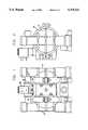
- FIG. 3is a cross-sectional elevation taken along the centerline of the pump.
- FIG. 4is a cross-sectional view taken centrally through the pump center section and actuator valve.
- FIG. 5is a plan view of an inner piston of the pump.
- an air driven double diaphragm pumpis illustrated.
- the pumpitself is found to be in three principal structural pieces, an air chamber housing 10 and two pump chamber housings 12 and 14. Clamp bands 16 and 18 hold these components together.
- the air chamber housing 10is shown to include two outwardly facing concave discs 20 and 22 which are integrally formed with a center section 24.
- the discs 20 and 22extend outwardly to a circular periphery having a form compatible with one of the clamp bands 16 and 18.
- a circular recess 26accommodates the periphery of a diaphragm.
- the center section 24includes a bushing 28.
- the bushing 28includes artifacts of an air driven reciprocating control valve.
- a plain bushing with a single 0-ring 30would suffice. Additional 0-rings and passages are illustrated which are unnecessary in this embodiment. Exhaust passages 32 and 34 vent air from the air chambers.
- control rod 36Located in the bushing 28 is a control rod 36.
- the control rod 36is slidably arranged and need not include the central passage 38 for purposes of this embodiment.
- the center section 24is shown to include supply passages 40 and 42.
- the supply passage 40extends through the concave disc 20 while the supply passage 42 extends through the concave disc 22 in the opposite direction.
- the two pump chamber housings 12 and 14may be identical. Each housing 12 and 14 includes a pump chamber shell 44 defining a pump chamber 46. Extending from the pump chamber shell 44 is an inlet passage 48 and an inlet check valve chamber 50. The inlet passages, in association with a T-coupling, form an inlet manifold.
- a spacer 52Contained within the inlet passage 48 and the inlet check valve chamber 50 is a spacer 52 threadably attached to one of the housings 12 and 14 with the junction sealed by an 0-ring 54.
- the spacer 52positions a valve seat 56 with an 0-ring 58 preventing bypass of the controlled passage.
- a ball valve 60cooperates with the valve seat 56 to form a one-way valve.
- a stop 62retains the ball valve 60 in position.
- outlet passage 64Also extending from the pump chamber shell 44 is an outlet passage 64 and an outlet check valve chamber 66.
- the outlet passagesin association with another T-coupling, form an outlet manifold.
- the outlet check valve chamber 66includes a seat 68.
- a ball valve 70cooperates with the seat 68 to provide a one-way check valve.
- a stop 72extends into the outlet check valve chamber 66 to retain position of the ball valve 70.
- the stop 72is threadably fixed within the outlet passage 64 and includes an 0-ring 74 to insure proper sealing.
- the two pump chamber housings 12 and 14also include a circular recess 76 to receive the periphery of the diaphragms.
- the outer portion of the pump chamber shell 44is circular and adapted to cooperate with one of the clamp bands 16 and 18.
- the diaphragmsmay be of conventional construction for air driven diaphragm pumps, defining with the concave discs 20 and 22 and the pump chamber shells 44 and air chamber and a pump chamber on either side of each diaphragm 78 and 80.
- Each diaphragm 78 and 80includes a center opening 82 for anchoring to the control rod 36.
- the control rod 36includes a threaded portion 84 at each end thereof. At each end, an inner piston 86 and an outer piston 88 cooperate to retain each of the diaphragms 78 and 80.
- a nut 90is threaded onto the control rod 36 at each end to retain the pistons 86 and 88.
- the inner pistons 86each include a stop surface 92 which is positioned to abut against the center section 24 to define the limits of the stroke of the control rod 36.
- the inner pistons 86may be available in varying thicknesses to accommodate different pump characteristics.
- an actuator valve 94Associated with the air driven diaphragm pump is an actuator valve 94.
- the actuator valve 94operates independently of the stroke position of the control rod 36.
- a solenoid 96controls the valve 94.
- Conventional electronic controlmay be employed to reciprocate the valve 94 through the solenoid 96 on a timed basis, on a pump flow basis, on a flow pressure basis or on external controls and circumstances.
- the actuator valve 94is shown to include a piston 98 having a central land 100 and two circumferential passages 102 and 104.
- a spring 106biases the piston 98 in a first direction to cooperate with the solenoid 96.
- Spacers 108 with 0-rings 110 therebetweenprevent communication axially along the valve.
- An inlet 112receives a constant pressurized source of air.
- Supply passages 40 and 42are alternately communicated with the inlet 112 depending on the position of the piston 98.
- the supply passage of the supply passages 40 and 42 which is not in communication with the inlet 112is in communication with its respective exhaust passage of the exhaust passages 32 and 34.
- the pumpis alternately driven in one direction or the other until it stalls against a stop surface 92 of one of the inner pistons 86.
- the thickness of the inner pistons 86may be selected to provide varying pump performance characteristics. For example, thick inner pistons 86 would act to minimize pressure surges. The thinner inner pistons 86 would maximize flow. Where each side is intended for a different pumping function, the inner pistons 86 may be of different thicknesses to accomplish different results. Finally, empirical selection of the thickness for each inner piston 86 would define a specific quantity of flow per stroke such that the pump itself may be used to accurately measure volumes.
Landscapes
- Engineering & Computer Science (AREA)
- Mechanical Engineering (AREA)
- General Engineering & Computer Science (AREA)
- Reciprocating Pumps (AREA)
Abstract
Description
Claims (3)
Priority Applications (2)
| Application Number | Priority Date | Filing Date | Title |
|---|---|---|---|
| US08/017,822US5378122A (en) | 1993-02-16 | 1993-02-16 | Air driven diaphragm pump |
| US09/566,416USRE38239E1 (en) | 1993-02-16 | 2000-05-05 | Air driven diaphragm pump |
Applications Claiming Priority (1)
| Application Number | Priority Date | Filing Date | Title |
|---|---|---|---|
| US08/017,822US5378122A (en) | 1993-02-16 | 1993-02-16 | Air driven diaphragm pump |
Related Child Applications (1)
| Application Number | Title | Priority Date | Filing Date |
|---|---|---|---|
| US09/566,416ReissueUSRE38239E1 (en) | 1993-02-16 | 2000-05-05 | Air driven diaphragm pump |
Publications (1)
| Publication Number | Publication Date |
|---|---|
| US5378122Atrue US5378122A (en) | 1995-01-03 |
Family
ID=21784729
Family Applications (2)
| Application Number | Title | Priority Date | Filing Date |
|---|---|---|---|
| US08/017,822CeasedUS5378122A (en) | 1993-02-16 | 1993-02-16 | Air driven diaphragm pump |
| US09/566,416Expired - LifetimeUSRE38239E1 (en) | 1993-02-16 | 2000-05-05 | Air driven diaphragm pump |
Family Applications After (1)
| Application Number | Title | Priority Date | Filing Date |
|---|---|---|---|
| US09/566,416Expired - LifetimeUSRE38239E1 (en) | 1993-02-16 | 2000-05-05 | Air driven diaphragm pump |
Country Status (1)
| Country | Link |
|---|---|
| US (2) | US5378122A (en) |
Cited By (33)
| Publication number | Priority date | Publication date | Assignee | Title |
|---|---|---|---|---|
| US5709536A (en)* | 1995-01-30 | 1998-01-20 | Titan Tool, Inc. | Hydro mechanical packingless pump and liquid spray system |
| US5894784A (en)* | 1998-08-10 | 1999-04-20 | Ingersoll-Rand Company | Backup washers for diaphragms and diaphragm pump incorporating same |
| US5957670A (en)* | 1997-08-26 | 1999-09-28 | Wilden Pump & Engineering Co. | Air driven diaphragm pump |
| US6071090A (en)* | 1996-08-12 | 2000-06-06 | Smc Corporation | Process pump |
| US6126403A (en)* | 1997-09-18 | 2000-10-03 | Yamada T.S. Co., Ltd. | Diaphragm pump |
| US6168394B1 (en)* | 1999-06-18 | 2001-01-02 | Wilden Pump & Engineering Co. | Air driven double diaphragm pump |
| US6168387B1 (en) | 1999-10-28 | 2001-01-02 | Ingersoll-Rand Company | Reciprocating pump with linear displacement sensor |
| US6280149B1 (en) | 1999-10-28 | 2001-08-28 | Ingersoll-Rand Company | Active feedback apparatus and air driven diaphragm pumps incorporating same |
| US6488641B2 (en) | 1998-03-12 | 2002-12-03 | Electromed, Inc. | Body pulsating apparatus |
| US20060104829A1 (en)* | 2004-11-17 | 2006-05-18 | Reed David A | Control system for an air operated diaphragm pump |
| US20070092386A1 (en)* | 2005-10-24 | 2007-04-26 | Reed David A | Method and control system for a pump |
| US20080000477A1 (en)* | 2006-03-15 | 2008-01-03 | Huster Keith A | High frequency chest wall oscillation system |
| US7399168B1 (en)* | 2005-12-19 | 2008-07-15 | Wilden Pump And Engineering Llc | Air driven diaphragm pump |
| US7527483B1 (en)* | 2004-11-18 | 2009-05-05 | Carl J Glauber | Expansible chamber pneumatic system |
| USRE40814E1 (en) | 1996-06-11 | 2009-06-30 | Hill-Rom Services, Inc. | Oscillatory chest compression device |
| US20090202361A1 (en)* | 2004-11-17 | 2009-08-13 | Proportion, Inc. | Control system for an air operated diaphragm pump |
| WO2010069321A2 (en) | 2008-12-19 | 2010-06-24 | Stobbe Tech A/S | Electronically controlled diaphragm pump |
| CN102410182A (en)* | 2011-11-28 | 2012-04-11 | 陈昌金 | Controllable pneumatic double-membrane diaphragm pump |
| CN103047128A (en)* | 2013-01-08 | 2013-04-17 | 曹雷钢 | Reversing valve for pneumatic diaphragm pump |
| US20150226206A1 (en)* | 2014-02-07 | 2015-08-13 | Graco Minnesota Inc. | Pulseless positive displacement pump and method of pulselessly displacing fluid |
| US9976545B2 (en) | 2014-01-31 | 2018-05-22 | Wilden Pump And Engineering Llc | Air operated pump |
| US10077763B2 (en) | 2015-03-25 | 2018-09-18 | Wilden Pump And Engineering Llc | Air operated pump |
| US10919060B2 (en) | 2008-10-22 | 2021-02-16 | Graco Minnesota Inc. | Portable airless sprayer |
| US10926275B1 (en) | 2020-06-25 | 2021-02-23 | Graco Minnesota Inc. | Electrostatic handheld sprayer |
| US10968903B1 (en) | 2020-06-04 | 2021-04-06 | Graco Minnesota Inc. | Handheld sanitary fluid sprayer having resilient polymer pump cylinder |
| US11007545B2 (en) | 2017-01-15 | 2021-05-18 | Graco Minnesota Inc. | Handheld airless paint sprayer repair |
| US11022106B2 (en) | 2018-01-09 | 2021-06-01 | Graco Minnesota Inc. | High-pressure positive displacement plunger pump |
| US11174854B2 (en) | 2020-03-31 | 2021-11-16 | Graco Minnesota Inc. | Electrically operated displacement pump control system and method |
| US11707753B2 (en) | 2019-05-31 | 2023-07-25 | Graco Minnesota Inc. | Handheld fluid sprayer |
| US11986850B2 (en) | 2018-04-10 | 2024-05-21 | Graco Minnesota Inc. | Handheld airless sprayer for paints and other coatings |
| US12116994B2 (en) | 2018-10-11 | 2024-10-15 | Psg Germany Gmbh | Diaphragm pump |
| US12345248B2 (en) | 2019-03-13 | 2025-07-01 | Psg Germany Gmbh | Valve assemblies for a diaphragm pump |
| US12366233B2 (en) | 2020-03-31 | 2025-07-22 | Graco Minnesota Inc. | Electrically operated pump for a plural component spray system |
Families Citing this family (15)
| Publication number | Priority date | Publication date | Assignee | Title |
|---|---|---|---|---|
| US7168928B1 (en) | 2004-02-17 | 2007-01-30 | Wilden Pump And Engineering Llc | Air driven hydraulic pump |
| US7063516B2 (en) | 2004-05-04 | 2006-06-20 | Wilden Pump And Engineering Llc | One-way valve |
| US7125229B2 (en) | 2004-05-10 | 2006-10-24 | Wilden Pump And Engineering Llc | Reciprocating air distribution system |
| JP4723218B2 (en)* | 2004-09-10 | 2011-07-13 | シーケーディ株式会社 | Chemical liquid supply pump unit |
| US8047222B2 (en)* | 2004-10-18 | 2011-11-01 | Wilden Pump And Engineering Llc | Air valve for an air driven reciprocating device |
| US7811067B2 (en) | 2006-04-19 | 2010-10-12 | Wilden Pump And Engineering Llc | Air driven pump with performance control |
| US7600532B2 (en)* | 2006-11-01 | 2009-10-13 | Ingersoll Rand Company | Check valve having integrally formed seat and seal body |
| US20100089456A1 (en)* | 2008-10-14 | 2010-04-15 | Circor Instrumentation Technologies, Inc. | Method and apparatus for low powered and/or high pressure flow control |
| BRPI1007538A2 (en) | 2009-01-23 | 2016-02-16 | Rupp Warren Inc | method, device, and method for detecting an optimum setpoint position of a pump diaphragm unit |
| ES2611209T3 (en)* | 2009-05-08 | 2017-05-05 | Warren Rupp, Inc. | Air operated diaphragm pump with electric generator |
| US8382445B2 (en)* | 2009-12-16 | 2013-02-26 | Warren Rupp, Inc. | Air logic controller |
| USD782541S1 (en)* | 2015-10-06 | 2017-03-28 | Graco Minnesota Inc. | Diaphragm pump |
| USD822067S1 (en)* | 2017-06-01 | 2018-07-03 | Graco Minnesota Inc. | Diaphragm pump |
| USD822720S1 (en)* | 2017-06-01 | 2018-07-10 | Graco Minnesota Inc. | Diaphragm pump |
| USD822719S1 (en)* | 2017-06-01 | 2018-07-10 | Graco Minnesota Inc. | Diaphragm pump |
Citations (1)
| Publication number | Priority date | Publication date | Assignee | Title |
|---|---|---|---|---|
| US4367140A (en)* | 1979-11-05 | 1983-01-04 | Sykes Ocean Water Ltd. | Reverse osmosis liquid purification apparatus |
Family Cites Families (38)
| Publication number | Priority date | Publication date | Assignee | Title |
|---|---|---|---|---|
| US1920014A (en) | 1931-06-26 | 1933-07-25 | Trico Products Corp | Multiple diaphragm pump |
| US2307566A (en) | 1940-07-31 | 1943-01-05 | Wright Aeronautical Corp | Pneumatic drive fuel pump |
| US2383193A (en) | 1943-11-01 | 1945-08-21 | Oliver United Felters Inc | Diaphragm pump |
| US2576747A (en) | 1946-01-24 | 1951-11-27 | Austin U Bryant | Liquid dispenser with means to vary a measured discharge |
| US2673522A (en) | 1951-04-10 | 1954-03-30 | Bendix Aviat Corp | Diaphragm pump |
| US2653552A (en) | 1951-08-15 | 1953-09-29 | Geeraert Corp | High-pressure pump |
| US2955539A (en) | 1959-05-28 | 1960-10-11 | Lawrence H Gardner | Positive displacement pump |
| US3071118A (en) | 1960-05-03 | 1963-01-01 | James K Wilden | Actuator valve means |
| US3250226A (en) | 1964-09-08 | 1966-05-10 | Allied Chem | Hydraulic actuated pumping system |
| US3288071A (en) | 1964-12-16 | 1966-11-29 | Herbert E Anderson | Chemical ratio feed pump |
| US3304126A (en) | 1965-02-15 | 1967-02-14 | Gorman Rupp Co | Material handling apparatus and methods |
| GB1117516A (en) | 1966-07-08 | 1968-06-19 | Thomas Henry Baggaley | Improvements in diaphragm pumps |
| GB1234921A (en) | 1969-01-06 | 1971-06-09 | Thomas Henry Baggaley | Improvements in diaphragm pumps |
| US3816034A (en) | 1971-03-12 | 1974-06-11 | Dorr Oliver Inc | Diaphragm pumps and actuating system therefor |
| US3814548A (en)* | 1971-08-05 | 1974-06-04 | Rupp Co Warren | Diaphragm pump apparatus |
| US3756456A (en) | 1972-05-22 | 1973-09-04 | Graco Inc | Apparatus and method for a metering system |
| US3913314A (en) | 1972-06-09 | 1975-10-21 | Westinghouse Electric Corp | System and method for operating a gas turbine electric power plant with bypass flow fueling operation to provide improved reliability and extended apparatus life |
| US4247264A (en)* | 1979-04-13 | 1981-01-27 | Wilden Pump & Engineering Co. | Air driven diaphragm pump |
| US4241602A (en) | 1979-04-20 | 1980-12-30 | Seismograph Service Corporation | Rheometer |
| DE2933327A1 (en) | 1979-08-17 | 1981-03-26 | Bayer Ag, 51373 Leverkusen | METHOD AND DEVICE FOR PRODUCING A FLOWABLE REACTION MIXTURE MAKING SOLID OR FOAM |
| US4315523A (en) | 1980-03-06 | 1982-02-16 | American Flow Systems, Inc. | Electronically controlled flow meter and flow control system |
| DE8107889U1 (en) | 1981-03-18 | 1981-10-22 | Festo-Maschinenfabrik Gottlieb Stoll, 7300 Esslingen | PNEUMATIC VALVE ARRANGEMENT |
| US4474309A (en) | 1981-10-22 | 1984-10-02 | Oximetrix, Inc. | Stepping motor control procedure for achieving variable rate, quasi-continuous fluid infusion |
| DE3203087A1 (en) | 1982-01-30 | 1983-08-04 | Gebrüder Sucker, 4050 Mönchengladbach | METHOD AND DEVICE FOR COATING OR IMRAEGNING A SUBSTRATE GUIDED IN A TRAIN |
| DE3204050C1 (en) | 1982-02-06 | 1983-07-21 | Chemie Und Filter Gmbh, Verfahrenstechnik Kg, 6900 Heidelberg | Electromagnetically operated axial piston pump, especially diaphragm pump |
| USD275858S (en)* | 1982-06-01 | 1984-10-09 | Wilden Pump & Engineering Co. | Double diaphragm pump |
| US4472115A (en) | 1982-09-07 | 1984-09-18 | The Warren Rupp Company | Fluid-operated reciprocating pump |
| US4549467A (en) | 1983-08-03 | 1985-10-29 | Wilden Pump & Engineering Co. | Actuator valve |
| USD294946S (en)* | 1984-08-06 | 1988-03-29 | Wilden Pump & Engineering Co. | Air driven diaphragm pump |
| USD294947S (en)* | 1984-08-06 | 1988-03-29 | Wilden Pump & Engineering Co. | Air driven diaphragm pump |
| US4778356A (en) | 1985-06-11 | 1988-10-18 | Hicks Cecil T | Diaphragm pump |
| US4597721A (en) | 1985-10-04 | 1986-07-01 | Valco Cincinnati, Inc. | Double acting diaphragm pump with improved disassembly means |
| US4796782A (en) | 1985-10-30 | 1989-01-10 | Automation, Inc. | Ink monitor system |
| DE3706338A1 (en) | 1987-02-27 | 1988-09-08 | Wagner Gmbh J | DIAPHRAGM PUMP DEVICE |
| US4897797A (en) | 1988-04-25 | 1990-01-30 | Betz Laboratories, Inc. | Proportional chemical feeding system |
| US5169296A (en) | 1989-03-10 | 1992-12-08 | Wilden James K | Air driven double diaphragm pump |
| US5056036A (en) | 1989-10-20 | 1991-10-08 | Pulsafeeder, Inc. | Computer controlled metering pump |
| US5326234A (en) | 1993-02-17 | 1994-07-05 | Versa-Matic Tool, Inc. | Fluid driven pump |
- 1993
- 1993-02-16USUS08/017,822patent/US5378122A/ennot_activeCeased
- 2000
- 2000-05-05USUS09/566,416patent/USRE38239E1/ennot_activeExpired - Lifetime
Patent Citations (1)
| Publication number | Priority date | Publication date | Assignee | Title |
|---|---|---|---|---|
| US4367140A (en)* | 1979-11-05 | 1983-01-04 | Sykes Ocean Water Ltd. | Reverse osmosis liquid purification apparatus |
Non-Patent Citations (2)
| Title |
|---|
| Valco s Electronically Controlled Diaphragm Pumps, 4 page publication.* |
| Valco's Electronically Controlled Diaphragm Pumps, 4-page publication. |
Cited By (70)
| Publication number | Priority date | Publication date | Assignee | Title |
|---|---|---|---|---|
| US5709536A (en)* | 1995-01-30 | 1998-01-20 | Titan Tool, Inc. | Hydro mechanical packingless pump and liquid spray system |
| USRE40814E1 (en) | 1996-06-11 | 2009-06-30 | Hill-Rom Services, Inc. | Oscillatory chest compression device |
| US6071090A (en)* | 1996-08-12 | 2000-06-06 | Smc Corporation | Process pump |
| US5957670A (en)* | 1997-08-26 | 1999-09-28 | Wilden Pump & Engineering Co. | Air driven diaphragm pump |
| US6126403A (en)* | 1997-09-18 | 2000-10-03 | Yamada T.S. Co., Ltd. | Diaphragm pump |
| US6488641B2 (en) | 1998-03-12 | 2002-12-03 | Electromed, Inc. | Body pulsating apparatus |
| US5894784A (en)* | 1998-08-10 | 1999-04-20 | Ingersoll-Rand Company | Backup washers for diaphragms and diaphragm pump incorporating same |
| US6168394B1 (en)* | 1999-06-18 | 2001-01-02 | Wilden Pump & Engineering Co. | Air driven double diaphragm pump |
| US6168387B1 (en) | 1999-10-28 | 2001-01-02 | Ingersoll-Rand Company | Reciprocating pump with linear displacement sensor |
| US6280149B1 (en) | 1999-10-28 | 2001-08-28 | Ingersoll-Rand Company | Active feedback apparatus and air driven diaphragm pumps incorporating same |
| US20060104829A1 (en)* | 2004-11-17 | 2006-05-18 | Reed David A | Control system for an air operated diaphragm pump |
| US8292600B2 (en) | 2004-11-17 | 2012-10-23 | Proportion-Air, Incorporated | Control system for an air operated diaphragm pump |
| US20090202361A1 (en)* | 2004-11-17 | 2009-08-13 | Proportion, Inc. | Control system for an air operated diaphragm pump |
| US7517199B2 (en) | 2004-11-17 | 2009-04-14 | Proportion Air Incorporated | Control system for an air operated diaphragm pump |
| US7527483B1 (en)* | 2004-11-18 | 2009-05-05 | Carl J Glauber | Expansible chamber pneumatic system |
| US7658598B2 (en) | 2005-10-24 | 2010-02-09 | Proportionair, Incorporated | Method and control system for a pump |
| US20070092386A1 (en)* | 2005-10-24 | 2007-04-26 | Reed David A | Method and control system for a pump |
| US7399168B1 (en)* | 2005-12-19 | 2008-07-15 | Wilden Pump And Engineering Llc | Air driven diaphragm pump |
| US20080000477A1 (en)* | 2006-03-15 | 2008-01-03 | Huster Keith A | High frequency chest wall oscillation system |
| US9968511B2 (en) | 2006-03-15 | 2018-05-15 | Hill-Rom Services Pte. Ltd. | High frequency chest wall oscillation system |
| US8460223B2 (en) | 2006-03-15 | 2013-06-11 | Hill-Rom Services Pte. Ltd. | High frequency chest wall oscillation system |
| US11110028B2 (en) | 2006-03-15 | 2021-09-07 | Hill-Rom Services Pte. Ltd. | High frequency chest wall oscillation system |
| US11759808B1 (en) | 2008-10-22 | 2023-09-19 | Graco Minnesota Inc. | Portable airless sprayer |
| US11446690B2 (en) | 2008-10-22 | 2022-09-20 | Graco Minnesota Inc. | Portable airless sprayer |
| US10919060B2 (en) | 2008-10-22 | 2021-02-16 | Graco Minnesota Inc. | Portable airless sprayer |
| US12145169B2 (en) | 2008-10-22 | 2024-11-19 | Graco Minnesota Inc. | Portable airless sprayer |
| US11779945B2 (en) | 2008-10-22 | 2023-10-10 | Graco Minnesota Inc. | Portable airless sprayer |
| US11446689B2 (en) | 2008-10-22 | 2022-09-20 | Graco Minnesota Inc. | Portable airless sprayer |
| US11623234B2 (en) | 2008-10-22 | 2023-04-11 | Graco Minnesota Inc. | Portable airless sprayer |
| US10508647B2 (en) | 2008-12-19 | 2019-12-17 | Stobbe Pharma Tech Gmbh | Electronically controlled diaphragm pump |
| US10288060B2 (en) | 2008-12-19 | 2019-05-14 | Stobbe Pharma Tech Gmbh | Electronically controlled diaphragm pump |
| WO2010069321A2 (en) | 2008-12-19 | 2010-06-24 | Stobbe Tech A/S | Electronically controlled diaphragm pump |
| CN102410182B (en)* | 2011-11-28 | 2014-03-19 | 陈昌金 | Controllable pneumatic double diaphragm pump |
| CN102410182A (en)* | 2011-11-28 | 2012-04-11 | 陈昌金 | Controllable pneumatic double-membrane diaphragm pump |
| CN103047128A (en)* | 2013-01-08 | 2013-04-17 | 曹雷钢 | Reversing valve for pneumatic diaphragm pump |
| CN103047128B (en)* | 2013-01-08 | 2015-07-01 | 曹雷钢 | Reversing valve for pneumatic diaphragm pump |
| US9976545B2 (en) | 2014-01-31 | 2018-05-22 | Wilden Pump And Engineering Llc | Air operated pump |
| US9784265B2 (en)* | 2014-02-07 | 2017-10-10 | Graco Minnesota Inc. | Electric drive system for a pulseless positive displacement pump |
| US20160108904A1 (en)* | 2014-02-07 | 2016-04-21 | Graco Minnesota Inc. | Pulseless positive displacement pump and method of pulselessly displacing fluid |
| US20150226207A1 (en)* | 2014-02-07 | 2015-08-13 | Graco Minnesota Inc. | Hydraulic drive system for a pulseless positive displacement pump |
| US10161393B2 (en)* | 2014-02-07 | 2018-12-25 | Graco Minnesota Inc. | Mechanical drive system for a pulseless positive displacement pump |
| US20190093651A1 (en)* | 2014-02-07 | 2019-03-28 | Graco Minnesota Inc. | Drive system for a positive displacement pump |
| CN105992873B (en)* | 2014-02-07 | 2018-01-19 | 固瑞克明尼苏达有限公司 | Drive system for pulsation-free positive displacement pumps |
| US9777721B2 (en)* | 2014-02-07 | 2017-10-03 | Graco Minnesota Inc. | Hydraulic drive system for a pulseless positive displacement pump |
| US9638185B2 (en)* | 2014-02-07 | 2017-05-02 | Graco Minnesota Inc. | Pulseless positive displacement pump and method of pulselessly displacing fluid |
| US20150226192A1 (en)* | 2014-02-07 | 2015-08-13 | Graco Minnesota Inc. | Electric drive system for a pulseless positive displacement pump |
| US12253071B2 (en) | 2014-02-07 | 2025-03-18 | Graco Minnesota Inc. | Drive system for a positive displacement pump |
| US11867165B2 (en) | 2014-02-07 | 2024-01-09 | Graco Minnesota Inc. | Drive system for a positive displacement pump |
| US20150226206A1 (en)* | 2014-02-07 | 2015-08-13 | Graco Minnesota Inc. | Pulseless positive displacement pump and method of pulselessly displacing fluid |
| US9777722B2 (en)* | 2014-02-07 | 2017-10-03 | Graco Minnesota Inc. | Pulseless positive displacement pump and method of pulselessly displacing fluid |
| US10072650B2 (en) | 2014-02-07 | 2018-09-11 | Graco Minnesota, Inc. | Method of pulselessly displacing fluid |
| US20150226205A1 (en)* | 2014-02-07 | 2015-08-13 | Graco Minnesota Inc. | Mechanical drive system for a pulseless positive displacement pump |
| CN105992873A (en)* | 2014-02-07 | 2016-10-05 | 固瑞克明尼苏达有限公司 | Drive system for a pulseless positive displacement pump |
| US10077763B2 (en) | 2015-03-25 | 2018-09-18 | Wilden Pump And Engineering Llc | Air operated pump |
| US11007545B2 (en) | 2017-01-15 | 2021-05-18 | Graco Minnesota Inc. | Handheld airless paint sprayer repair |
| US12172181B2 (en) | 2017-01-15 | 2024-12-24 | Graco Minnesota Inc. | Airless handheld sprayer repair |
| US11022106B2 (en) | 2018-01-09 | 2021-06-01 | Graco Minnesota Inc. | High-pressure positive displacement plunger pump |
| US11986850B2 (en) | 2018-04-10 | 2024-05-21 | Graco Minnesota Inc. | Handheld airless sprayer for paints and other coatings |
| US12116994B2 (en) | 2018-10-11 | 2024-10-15 | Psg Germany Gmbh | Diaphragm pump |
| US12345248B2 (en) | 2019-03-13 | 2025-07-01 | Psg Germany Gmbh | Valve assemblies for a diaphragm pump |
| US12208411B2 (en) | 2019-05-31 | 2025-01-28 | Graco Minnesota Inc. | Handheld fluid sprayer |
| US11707753B2 (en) | 2019-05-31 | 2023-07-25 | Graco Minnesota Inc. | Handheld fluid sprayer |
| US12092090B2 (en) | 2020-03-31 | 2024-09-17 | Graco Minnesota Inc. | Electrically operated displacement pump control system and method |
| US11655810B2 (en) | 2020-03-31 | 2023-05-23 | Graco Minnesota Inc. | Electrically operated displacement pump control system and method |
| US11434892B2 (en) | 2020-03-31 | 2022-09-06 | Graco Minnesota Inc. | Electrically operated displacement pump assembly |
| US11174854B2 (en) | 2020-03-31 | 2021-11-16 | Graco Minnesota Inc. | Electrically operated displacement pump control system and method |
| US12366233B2 (en) | 2020-03-31 | 2025-07-22 | Graco Minnesota Inc. | Electrically operated pump for a plural component spray system |
| US10968903B1 (en) | 2020-06-04 | 2021-04-06 | Graco Minnesota Inc. | Handheld sanitary fluid sprayer having resilient polymer pump cylinder |
| US11738358B2 (en) | 2020-06-25 | 2023-08-29 | Graco Minnesota Inc. | Electrostatic handheld sprayer |
| US10926275B1 (en) | 2020-06-25 | 2021-02-23 | Graco Minnesota Inc. | Electrostatic handheld sprayer |
Also Published As
| Publication number | Publication date |
|---|---|
| USRE38239E1 (en) | 2003-08-26 |
Similar Documents
| Publication | Publication Date | Title |
|---|---|---|
| US5378122A (en) | Air driven diaphragm pump | |
| US5213485A (en) | Air driven double diaphragm pump | |
| US5169296A (en) | Air driven double diaphragm pump | |
| EP0304210B1 (en) | Double diaphragm pumps | |
| US5362212A (en) | Air driven diaphragm pump | |
| US5564911A (en) | Pump, control valve and diaphragm | |
| US7399168B1 (en) | Air driven diaphragm pump | |
| US4830586A (en) | Double acting diaphragm pump | |
| US7168928B1 (en) | Air driven hydraulic pump | |
| EP0711905B1 (en) | Improved mechanical shift, pneumatic assist pilot valve | |
| WO2002040863A2 (en) | Pump and diaphragm for use therein | |
| US5441281A (en) | Shaft seal | |
| AU2002225077A1 (en) | Electronic micro-pump | |
| US4271989A (en) | Micro-metering system | |
| CA1122479A (en) | Double-acting differential piston supply pump | |
| GB1409412A (en) | Tubular diaphragm liquid pump | |
| CA2213194A1 (en) | Multiple piston pump | |
| US5433240A (en) | Low-ratio proportioner | |
| AU665916B2 (en) | Pneumatically actuated lubricant pump | |
| US7367785B2 (en) | Reduced icing valves and gas-driven motor and reciprocating pump incorporating same | |
| US4827832A (en) | Valve system for a reciprocating device | |
| US4721444A (en) | Fluid pump incorporating pulsation dampener surrounding its shaft | |
| US3583832A (en) | Booster | |
| EP0167274A2 (en) | Pump | |
| JPH0319916B2 (en) |
Legal Events
| Date | Code | Title | Description |
|---|---|---|---|
| AS | Assignment | Owner name:WILDEN PUMP & ENGINEERING CO., CALIFORNIA Free format text:ASSIGNMENT OF ASSIGNORS INTEREST.;ASSIGNOR:DUNCAN, GREG S.;REEL/FRAME:006439/0965 Effective date:19930119 | |
| STCF | Information on status: patent grant | Free format text:PATENTED CASE | |
| FPAY | Fee payment | Year of fee payment:4 | |
| RF | Reissue application filed | Effective date:20000505 | |
| CC | Certificate of correction | ||
| FEPP | Fee payment procedure | Free format text:PAT HOLDER NO LONGER CLAIMS SMALL ENTITY STATUS, ENTITY STATUS SET TO UNDISCOUNTED (ORIGINAL EVENT CODE: STOL); ENTITY STATUS OF PATENT OWNER: LARGE ENTITY | |
| REFU | Refund | Free format text:REFUND - PAYMENT OF MAINTENANCE FEE, 8TH YR, SMALL ENTITY (ORIGINAL EVENT CODE: R284); ENTITY STATUS OF PATENT OWNER: LARGE ENTITY | |
| FPAY | Fee payment | Year of fee payment:8 | |
| FEPP | Fee payment procedure | Free format text:PAYOR NUMBER ASSIGNED (ORIGINAL EVENT CODE: ASPN); ENTITY STATUS OF PATENT OWNER: LARGE ENTITY Free format text:PAYER NUMBER DE-ASSIGNED (ORIGINAL EVENT CODE: RMPN); ENTITY STATUS OF PATENT OWNER: LARGE ENTITY | |
| AS | Assignment | Owner name:DOVER RESOURCES PUMP ENGINEERING COMPANY, CALIFORN Free format text:ARTICLES OF INCORPORATION;ASSIGNOR:WILDEN PUMP AND ENGINEERING COMPANY;REEL/FRAME:014373/0038 Effective date:19980806 Owner name:WILDEN PUMP AND ENGINEERING COMPANY, DELAWARE Free format text:MERGER;ASSIGNOR:DOVER RESOURCES PUMP ENGINEERING COMPANY;REEL/FRAME:014373/0001 Effective date:19980806 Owner name:WILDEN PUMP AND ENGINEERING LLC, DELAWARE Free format text:ASSIGNMENT OF ASSIGNORS INTEREST;ASSIGNOR:WILDEN PUMP AND ENGINEERING COMPANY;REEL/FRAME:014373/0102 Effective date:20021223 |