US5377685A - Ultrasound catheter with mechanically steerable beam - Google Patents
Ultrasound catheter with mechanically steerable beamDownload PDFInfo
- Publication number
- US5377685A US5377685AUS08/169,306US16930693AUS5377685AUS 5377685 AUS5377685 AUS 5377685AUS 16930693 AUS16930693 AUS 16930693AUS 5377685 AUS5377685 AUS 5377685A
- Authority
- US
- United States
- Prior art keywords
- head
- catheter
- base
- tip member
- shaft
- Prior art date
- Legal status (The legal status is an assumption and is not a legal conclusion. Google has not performed a legal analysis and makes no representation as to the accuracy of the status listed.)
- Expired - Lifetime
Links
- 238000002604ultrasonographyMethods0.000titleclaimsdescription31
- 238000010438heat treatmentMethods0.000claimsabstractdescription10
- 239000003550markerSubstances0.000claimsabstractdescription9
- 239000004020conductorSubstances0.000claimsdescription14
- 239000000463materialSubstances0.000claimsdescription9
- 229920003023plasticPolymers0.000claimsdescription5
- 230000008054signal transmissionEffects0.000claimsdescription5
- 239000012781shape memory materialSubstances0.000claimsdescription3
- 239000002775capsuleSubstances0.000abstractdescription5
- 229910001285shape-memory alloyInorganic materials0.000abstractdescription5
- 210000004204blood vesselAnatomy0.000description16
- 239000000523sampleSubstances0.000description7
- 210000005242cardiac chamberAnatomy0.000description4
- 238000003384imaging methodMethods0.000description3
- 239000013078crystalSubstances0.000description2
- 238000001514detection methodMethods0.000description2
- 238000010586diagramMethods0.000description2
- 230000007246mechanismEffects0.000description2
- HZEWFHLRYVTOIW-UHFFFAOYSA-N[Ti].[Ni]Chemical group[Ti].[Ni]HZEWFHLRYVTOIW-UHFFFAOYSA-N0.000description1
- 229910045601alloyInorganic materials0.000description1
- 239000000956alloySubstances0.000description1
- 208000021328arterial occlusionDiseases0.000description1
- 210000001367arteryAnatomy0.000description1
- 230000003247decreasing effectEffects0.000description1
- 229920002457flexible plasticPolymers0.000description1
- 239000011810insulating materialSubstances0.000description1
- 238000002608intravascular ultrasoundMethods0.000description1
- 238000005259measurementMethods0.000description1
- 229910001000nickel titaniumInorganic materials0.000description1
- 238000005476solderingMethods0.000description1
- 210000003462veinAnatomy0.000description1
Images


Classifications
- A—HUMAN NECESSITIES
- A61—MEDICAL OR VETERINARY SCIENCE; HYGIENE
- A61B—DIAGNOSIS; SURGERY; IDENTIFICATION
- A61B8/00—Diagnosis using ultrasonic, sonic or infrasonic waves
- A61B8/12—Diagnosis using ultrasonic, sonic or infrasonic waves in body cavities or body tracts, e.g. by using catheters
- A—HUMAN NECESSITIES
- A61—MEDICAL OR VETERINARY SCIENCE; HYGIENE
- A61B—DIAGNOSIS; SURGERY; IDENTIFICATION
- A61B8/00—Diagnosis using ultrasonic, sonic or infrasonic waves
- A61B8/44—Constructional features of the ultrasonic, sonic or infrasonic diagnostic device
- A61B8/4444—Constructional features of the ultrasonic, sonic or infrasonic diagnostic device related to the probe
- A61B8/445—Details of catheter construction
- A—HUMAN NECESSITIES
- A61—MEDICAL OR VETERINARY SCIENCE; HYGIENE
- A61B—DIAGNOSIS; SURGERY; IDENTIFICATION
- A61B8/00—Diagnosis using ultrasonic, sonic or infrasonic waves
- A61B8/44—Constructional features of the ultrasonic, sonic or infrasonic diagnostic device
- A61B8/4444—Constructional features of the ultrasonic, sonic or infrasonic diagnostic device related to the probe
- A61B8/4461—Features of the scanning mechanism, e.g. for moving the transducer within the housing of the probe
- G—PHYSICS
- G01—MEASURING; TESTING
- G01S—RADIO DIRECTION-FINDING; RADIO NAVIGATION; DETERMINING DISTANCE OR VELOCITY BY USE OF RADIO WAVES; LOCATING OR PRESENCE-DETECTING BY USE OF THE REFLECTION OR RERADIATION OF RADIO WAVES; ANALOGOUS ARRANGEMENTS USING OTHER WAVES
- G01S15/00—Systems using the reflection or reradiation of acoustic waves, e.g. sonar systems
- G01S15/88—Sonar systems specially adapted for specific applications
- G01S15/89—Sonar systems specially adapted for specific applications for mapping or imaging
- G01S15/8906—Short-range imaging systems; Acoustic microscope systems using pulse-echo techniques
- G01S15/8934—Short-range imaging systems; Acoustic microscope systems using pulse-echo techniques using a dynamic transducer configuration
- G01S15/8936—Short-range imaging systems; Acoustic microscope systems using pulse-echo techniques using a dynamic transducer configuration using transducers mounted for mechanical movement in three dimensions
- G—PHYSICS
- G01—MEASURING; TESTING
- G01S—RADIO DIRECTION-FINDING; RADIO NAVIGATION; DETERMINING DISTANCE OR VELOCITY BY USE OF RADIO WAVES; LOCATING OR PRESENCE-DETECTING BY USE OF THE REFLECTION OR RERADIATION OF RADIO WAVES; ANALOGOUS ARRANGEMENTS USING OTHER WAVES
- G01S15/00—Systems using the reflection or reradiation of acoustic waves, e.g. sonar systems
- G01S15/88—Sonar systems specially adapted for specific applications
- G01S15/89—Sonar systems specially adapted for specific applications for mapping or imaging
- G01S15/8906—Short-range imaging systems; Acoustic microscope systems using pulse-echo techniques
- G01S15/8934—Short-range imaging systems; Acoustic microscope systems using pulse-echo techniques using a dynamic transducer configuration
- G01S15/8938—Short-range imaging systems; Acoustic microscope systems using pulse-echo techniques using a dynamic transducer configuration using transducers mounted for mechanical movement in two dimensions
- G01S15/894—Short-range imaging systems; Acoustic microscope systems using pulse-echo techniques using a dynamic transducer configuration using transducers mounted for mechanical movement in two dimensions by rotation about a single axis
- G—PHYSICS
- G01—MEASURING; TESTING
- G01S—RADIO DIRECTION-FINDING; RADIO NAVIGATION; DETERMINING DISTANCE OR VELOCITY BY USE OF RADIO WAVES; LOCATING OR PRESENCE-DETECTING BY USE OF THE REFLECTION OR RERADIATION OF RADIO WAVES; ANALOGOUS ARRANGEMENTS USING OTHER WAVES
- G01S15/00—Systems using the reflection or reradiation of acoustic waves, e.g. sonar systems
- G01S15/88—Sonar systems specially adapted for specific applications
- G01S15/89—Sonar systems specially adapted for specific applications for mapping or imaging
- G01S15/8906—Short-range imaging systems; Acoustic microscope systems using pulse-echo techniques
- G01S15/899—Combination of imaging systems with ancillary equipment
Definitions
- the present inventionrelates to an intravascular or intra-cardiac ultrasound catheter of the type which is rotated within a heart chamber, an artery or vein to produce an ultrasound image of the interior of the blood vessel or heart.
- the inventionrelates further to such a catheter which is able to produce an image at a desired position forward of the catheter tip by controlling the angle of the ultrasound beam with respect to its rotation axis through a range.
- Miniature ultrasound probes for imaging blood vesselsare well known in the art (for example, see U.S. Pat. No. 4,576,177 to Webster, Jr.).
- the catheterhas an outer tube containing a rotatable flexible shaft connected to an ultrasound transducer tip (see U.S. Pat. No. 4,794,931).
- an ultrasound transducer tipBy rotating the transducer tip, a two dimensional image slice of the blood vessel can be obtained.
- By linearly moving the ultrasound transducer inside the outer tube, or by moving the outer tube within the blood vesselimages of the blood vessel at various points can be obtained.
- the ability to image forward of the catheter tip at a controllable distance and angle in front of the tiphas been either difficult or not possible.
- an ultrasound cathetercomprising an outer tube having a lumen, a sonolucent closed distal end and a proximal end, a rotatable drive shaft provided in the lumen, the shaft including an electric signal transmission cable, a tip member connected to the shaft and provided at the distal end, the tip member having a lengthwise axis of rotation when rotated by the shaft, an ultrasound transducer mounted in the tip member and connected to the cable for generating an ultrasound beam, and beam directing means for directing the ultrasound beam radially outward with respect to the lengthwise axis at a variable angle thereto and for controllably adjusting the angle.
- an ultrasonograph forward of the tip at a desired distance and anglecan be obtained by rotation of the drive shaft and adjustment of the angle.
- the beam anglecan be controllably adjusted according to the invention by pivoting the transducer, reflecting the beam emitted by a fixed transducer off a pivoting planar mirror, or reflecting the beam emitted by a fixed transducer off a curved linearly translatable mirror.
- the transducerWhen the transducer is designed to pivot, it can be mounted in a ball-and-socket mount or a pivot/hinge mount.
- the beam directing meanscan be provided by one of a variety of actuator mechanisms to cause the pivoting or translation required to adjust the beam angle.
- Shape memory alloy wires electrically heated to controllably contractare one possibility for making a suitable actuator.
- the forward-reverse action of the actuationcan be provided by a pair of actuators working in opposite directions or by a single actuator acting against an opposed spring member. Whatever the mechanism chosen, it is important that the beam angle does not fluctuate as the beam is rotated. It is also desirable to be able to control the exact beam angle.
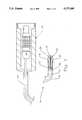
- FIG. 1is a break-away side view of the catheter according to the preferred embodiment
- FIG. 2is a block diagram of the system according to the preferred embodiment
- FIG. 3is a detailed side view of the catheter tip according to the preferred embodiment
- FIG. 4is a break-away end view of the catheter tip showing the tip connector contacts
- FIG. 5is a detailed front view of the catheter tip according to the preferred embodiment.
- FIG. 6is a detailed break-away side view of the catheter tip and pivoting head according to the preferred embodiment.
- FIG. 7is a detailed side cut-away view of the tip-to-shaft connector.
- a thin flexible plastic outer tube (12)has one end connected to a base connector unit (60) and another end connected to a sonolucent chamber capsule (16).
- a flexible drive shaft (50)is provided in the lumen of tube (12) and is driven by a rotatable member (62) inside connector (60) at the proximal end and is connected to a connector (40) at its distal end.
- a catheter tip (20)is connected to connector (40) and electrical wires passing through a hollow core in flexible drive shaft (50) connect shape memory alloy wires (30) and transducer (28) to rotatable member (62) which transfers the electrical signals through slip rings to the external circuitry.
- transducer (28)also rotates inside sonolucent chamber capsule (16).
- Lumen (14)is in practice filled with a sonolucent solution, and a thin marker wire (18) is embedded into the surface of capsule (16) to give a reference marker to transducer (28).
- the diameter of plastic tube (12)is about 3 mm, however, smaller dimensions are possible and are desirable in order to be able to image blood vessels with a smaller diameter.
- FIG. 2a block diagram of the control system for the catheter system (10) is illustrated.
- An ultrasound signal generator and processor (72)is connected via rotatable member (62) and a coax (96) provided inside drive shaft (50) to piezoelectric crystal (28).
- the crystalWhen the crystal is stimulated to produce ultrasonic waves, the echo or reflected waves from the sidewall of the blood vessel or heart chamber stimulates an electric signal in the transducer (28) and produces a return signal which can be processed by the signal processor (72) to provide a measurement of the distance between transducer (28) and the blood vessel sidewall.
- the amplitude or intensity of the reflected ultrasound beamis indicative of the nature of the material reflecting the beam. For example, a softer material will absorb more and reflect less of the beam than a harder material. Thus, the amplitude of the reflected beam is used to characterize and/or identify the material of the blood vessel sidewall or heart chamber.
- An image beam control unit (78)specifies the speed of rotation to motor controller (82) which controls motor (84) to turn drive shaft (50) at a specified rotational speed.
- a marker feedback detector unit (80)distinguishes detection of marker (18) from detection of the blood vessel sidewall. Based on the distance detected and the duration of the marker echo signal, unit (80) determines the angle of transducer (28) with respect to the axis of rotation.
- Control unit (78)signals the shape memory alloy wire heating control unit (74) which direction of movement of transducer (28) is desired in order that the control unit (74) may respond by increasing or decreasing current to one of the wires (30). Current from the control unit (74) is fed to wires (30) through connector (62) and conductors contained in drive shaft (50).
- Unit (74)may comprise a pulse width modulated constant voltage source as is well known in the art.
- Image beam control unit (78)also informs the image generator as to the transducer angle in order that image generator (76) may display image position data along with the image.
- transducer (28)can be used to control the image position, as well as the kind of image, i.e. cross-section, longitudinal section or even a 3-D surface image.
- tip member (20)has a base (22) and a head (24) connected to the base (22) by an integral or living hinge portion (26).
- Two shape memory material wires (30)extend along the surface of body (22) and through holes (34) as shown in FIGS. 3, 4 and 5.
- the free ends of wires (30)wrap around the rear edge of body (22) into a socket (36) which receives connector plug (42) of connector (40) and then pass through holes (32).
- the wires (30)are threaded to loop through socket (36) to keep the wires taut.
- the connector plug (42)is divided by insulating portions (44) and provides electrical contact between wires (30) and conductors in drive shaft (50). The plug (42) also keeps the wires (30) tightly connected. As detailed in FIG.
- the plug (42)has a socket (90) for receiving shaft (50), and three channels (91), (91') and (92) for guiding three small coaxial conductors (95), (95') and (96) from shaft (50).
- Plug (42) and connector (40)comprise four conductive segments connected together by an insulating material. Each conductor (95) and (95') has one wire soldered at neck (93) to opposite "live” segments, while the other two conducting segments are grounded (by the ground wires of conductors (95), not shown). Thus, soldering directly to the shaped memory alloy wires is avoided.
- a deformation (shrinking) of about 4% to 6% of the length of the wirecan be repeatedly created which results in flexing of head (24) in the direction of the heated wire (while the non-heated wire is stretched).
- head (24)When current through the wire is stopped, it returns to ambient temperature within a short time and head (24) returns to its initial position.
- head (24)By balancing current between the two wires (30), head (24) may be pivoted about hinge (26) to flex 45° in either direction resulting in transducer (28) being substantially directed along the axis of rotation of body (22) or perpendicular to the lengthwise axis of rotation.
- the shape memory material in the preferred embodimentis a nickel-titanium (50:50) alloy wire having a diameter of 75 ⁇ m. It is important to operate the wires within their elastic limits.
- An axial bore (25) shown in FIGS. 3, 4 and 5provides a passageway for electrical conductor (96) to lead from shaft (50) to transducer (28).
- a pair of diodes (46)may be provided to direct positive current from a single electrical line (48) to one of the wires (30) and negative current to the other wire (30). This arrangement also prevents heating of both wires (30) simultaneously, which may not be desirable.
- FIG. 6shows a detailed view of tip (20) inside tube (12) and sonolucent chamber (16).
- the reference marker strip (18)is a thin wire embedded in an outside of capsule (16) in a plane parallel to the axis of rotation.
- marker strip (18)provides a reference signal in order that the beam angle of the ultrasound beam may be determined as well as the zero position of the tip (20) as it is rotated.
- Head (24)is shown to be somewhat symmetrical in shape, and is able to be flexed 45° in either direction in order to sweep the beam angle of transducer (28) from parallel to the axis of rotation to being perpendicular to the lengthwise axis.
- the beam anglecan be calculated by the distance between the transducer (28) and the wire (18) as well as the fraction of the time the wire echo signal is present with respect to the cycle period, that is the time between consecutive appearances of the wire echo signal.
Landscapes
- Health & Medical Sciences (AREA)
- Engineering & Computer Science (AREA)
- Physics & Mathematics (AREA)
- Life Sciences & Earth Sciences (AREA)
- Radar, Positioning & Navigation (AREA)
- Remote Sensing (AREA)
- Acoustics & Sound (AREA)
- Animal Behavior & Ethology (AREA)
- Molecular Biology (AREA)
- Biophysics (AREA)
- Nuclear Medicine, Radiotherapy & Molecular Imaging (AREA)
- Pathology (AREA)
- Radiology & Medical Imaging (AREA)
- Biomedical Technology (AREA)
- Heart & Thoracic Surgery (AREA)
- Medical Informatics (AREA)
- Veterinary Medicine (AREA)
- Surgery (AREA)
- Public Health (AREA)
- General Health & Medical Sciences (AREA)
- Computer Networks & Wireless Communication (AREA)
- General Physics & Mathematics (AREA)
- Ultra Sonic Daignosis Equipment (AREA)
- Media Introduction/Drainage Providing Device (AREA)
Abstract
Description
The present invention relates to an intravascular or intra-cardiac ultrasound catheter of the type which is rotated within a heart chamber, an artery or vein to produce an ultrasound image of the interior of the blood vessel or heart. The invention relates further to such a catheter which is able to produce an image at a desired position forward of the catheter tip by controlling the angle of the ultrasound beam with respect to its rotation axis through a range.
Miniature ultrasound probes for imaging blood vessels are well known in the art (for example, see U.S. Pat. No. 4,576,177 to Webster, Jr.). In conventional imaging systems, the catheter has an outer tube containing a rotatable flexible shaft connected to an ultrasound transducer tip (see U.S. Pat. No. 4,794,931). By rotating the transducer tip, a two dimensional image slice of the blood vessel can be obtained. By linearly moving the ultrasound transducer inside the outer tube, or by moving the outer tube within the blood vessel, images of the blood vessel at various points can be obtained. The ability to image forward of the catheter tip at a controllable distance and angle in front of the tip has been either difficult or not possible.
In U.S. Pat. No. 5,174,296, an ultrasound probe is described which looks forward into a blood vessel with a pie segmented piezoelectric transducer facing forward with each segment at a different angle with respect to the rotation axis. While such a probe can produce images at different forward positions without requiring linear movement, and in a forward direction (this allows an arterial obstruction to be imaged before reaching it), the very small piezoelectric segments have limited imaging power, and therefore the ability to image clearly is reduced.
It is an object of the invention to provide an ultrasound catheter probe which is able to generate an image of a blood vessel inside section or the heart by rotation of the ultrasound beam about a lengthwise axis of the catheter and by adjusting an angle of the beam with respect to the lengthwise axis.
It is also an object of the invention to provide an intravascular ultrasound catheter probe which is able to generate an image of a blood vessel at a controllable point forward of the catheter tip. Similarly, it is an object of the invention to provide an intra-cardiac ultrasound catheter probe which is able to generate an image within the various chambers of the heart at a controllable point forward of the catheter tip.
It is a further object of the invention to provide an intravascular or intra-cardiac ultrasound catheter probe which is able to vary its beam angle to view a blood vessel wall or heart chamber at different angles resulting in different image characteristics.
According to the invention, there is provided an ultrasound catheter comprising an outer tube having a lumen, a sonolucent closed distal end and a proximal end, a rotatable drive shaft provided in the lumen, the shaft including an electric signal transmission cable, a tip member connected to the shaft and provided at the distal end, the tip member having a lengthwise axis of rotation when rotated by the shaft, an ultrasound transducer mounted in the tip member and connected to the cable for generating an ultrasound beam, and beam directing means for directing the ultrasound beam radially outward with respect to the lengthwise axis at a variable angle thereto and for controllably adjusting the angle. In this way, an ultrasonograph forward of the tip at a desired distance and angle can be obtained by rotation of the drive shaft and adjustment of the angle.
The beam angle can be controllably adjusted according to the invention by pivoting the transducer, reflecting the beam emitted by a fixed transducer off a pivoting planar mirror, or reflecting the beam emitted by a fixed transducer off a curved linearly translatable mirror. When the transducer is designed to pivot, it can be mounted in a ball-and-socket mount or a pivot/hinge mount. The beam directing means can be provided by one of a variety of actuator mechanisms to cause the pivoting or translation required to adjust the beam angle. Shape memory alloy wires electrically heated to controllably contract are one possibility for making a suitable actuator. The forward-reverse action of the actuation can be provided by a pair of actuators working in opposite directions or by a single actuator acting against an opposed spring member. Whatever the mechanism chosen, it is important that the beam angle does not fluctuate as the beam is rotated. It is also desirable to be able to control the exact beam angle.
Further features of the invention will be better understood by way of the following non-limiting detailed description of a preferred embodiment with reference to the appended drawings, in which:
FIG. 1 is a break-away side view of the catheter according to the preferred embodiment;
FIG. 2 is a block diagram of the system according to the preferred embodiment;
FIG. 3 is a detailed side view of the catheter tip according to the preferred embodiment;
FIG. 4 is a break-away end view of the catheter tip showing the tip connector contacts;
FIG. 5 is a detailed front view of the catheter tip according to the preferred embodiment;
FIG. 6 is a detailed break-away side view of the catheter tip and pivoting head according to the preferred embodiment; and
FIG. 7 is a detailed side cut-away view of the tip-to-shaft connector.
With reference to FIG. 1, the catheter system (10) according to the preferred embodiment will be described. A thin flexible plastic outer tube (12) has one end connected to a base connector unit (60) and another end connected to a sonolucent chamber capsule (16). A flexible drive shaft (50) is provided in the lumen of tube (12) and is driven by a rotatable member (62) inside connector (60) at the proximal end and is connected to a connector (40) at its distal end. A catheter tip (20) is connected to connector (40) and electrical wires passing through a hollow core in flexible drive shaft (50) connect shape memory alloy wires (30) and transducer (28) to rotatable member (62) which transfers the electrical signals through slip rings to the external circuitry. As rotatable member (62) is rotated, drive shaft (50) is also rotated resulting in rotation of tip (20) inside lumen (14) such that transducer (28) also rotates inside sonolucent chamber capsule (16). Lumen (14) is in practice filled with a sonolucent solution, and a thin marker wire (18) is embedded into the surface of capsule (16) to give a reference marker to transducer (28). The diameter of plastic tube (12) is about 3 mm, however, smaller dimensions are possible and are desirable in order to be able to image blood vessels with a smaller diameter.
With reference to FIG. 2, a block diagram of the control system for the catheter system (10) is illustrated. An ultrasound signal generator and processor (72) is connected via rotatable member (62) and a coax (96) provided inside drive shaft (50) to piezoelectric crystal (28). When the crystal is stimulated to produce ultrasonic waves, the echo or reflected waves from the sidewall of the blood vessel or heart chamber stimulates an electric signal in the transducer (28) and produces a return signal which can be processed by the signal processor (72) to provide a measurement of the distance between transducer (28) and the blood vessel sidewall. The amplitude or intensity of the reflected ultrasound beam is indicative of the nature of the material reflecting the beam. For example, a softer material will absorb more and reflect less of the beam than a harder material. Thus, the amplitude of the reflected beam is used to characterize and/or identify the material of the blood vessel sidewall or heart chamber.
An image beam control unit (78) specifies the speed of rotation to motor controller (82) which controls motor (84) to turn drive shaft (50) at a specified rotational speed. A marker feedback detector unit (80) distinguishes detection of marker (18) from detection of the blood vessel sidewall. Based on the distance detected and the duration of the marker echo signal, unit (80) determines the angle of transducer (28) with respect to the axis of rotation. Control unit (78) signals the shape memory alloy wire heating control unit (74) which direction of movement of transducer (28) is desired in order that the control unit (74) may respond by increasing or decreasing current to one of the wires (30). Current from the control unit (74) is fed to wires (30) through connector (62) and conductors contained in drive shaft (50). Unit (74) may comprise a pulse width modulated constant voltage source as is well known in the art. Image beam control unit (78) also informs the image generator as to the transducer angle in order that image generator (76) may display image position data along with the image.
Although a conventional ultrasonograph shows the interior cross-sectional of the blood vessel at a fixed view angle, it is also possible according to the invention to cause transducer (28) to "sweep" through a range of angles, i.e. forward positions, and display a longitudinal section of the blood vessel about a plane co-extensive with the rotational axis of the tip (20). A user input, such as keypad (86) can be used to control the image position, as well as the kind of image, i.e. cross-section, longitudinal section or even a 3-D surface image.
As shown in FIG. 3, tip member (20) has a base (22) and a head (24) connected to the base (22) by an integral or living hinge portion (26). Two shape memory material wires (30) extend along the surface of body (22) and through holes (34) as shown in FIGS. 3, 4 and 5. The free ends of wires (30) wrap around the rear edge of body (22) into a socket (36) which receives connector plug (42) of connector (40) and then pass through holes (32). The wires (30) are threaded to loop through socket (36) to keep the wires taut. The connector plug (42) is divided by insulating portions (44) and provides electrical contact between wires (30) and conductors in drive shaft (50). The plug (42) also keeps the wires (30) tightly connected. As detailed in FIG. 7, the plug (42) has a socket (90) for receiving shaft (50), and three channels (91), (91') and (92) for guiding three small coaxial conductors (95), (95') and (96) from shaft (50). Plug (42) and connector (40) comprise four conductive segments connected together by an insulating material. Each conductor (95) and (95') has one wire soldered at neck (93) to opposite "live" segments, while the other two conducting segments are grounded (by the ground wires of conductors (95), not shown). Thus, soldering directly to the shaped memory alloy wires is avoided.
By providing an ohmic heating current source to one of wires (30), a deformation (shrinking) of about 4% to 6% of the length of the wire can be repeatedly created which results in flexing of head (24) in the direction of the heated wire (while the non-heated wire is stretched). When current through the wire is stopped, it returns to ambient temperature within a short time and head (24) returns to its initial position. By balancing current between the two wires (30), head (24) may be pivoted about hinge (26) to flex 45° in either direction resulting in transducer (28) being substantially directed along the axis of rotation of body (22) or perpendicular to the lengthwise axis of rotation. The shape memory material in the preferred embodiment is a nickel-titanium (50:50) alloy wire having a diameter of 75 μm. It is important to operate the wires within their elastic limits. An axial bore (25) shown in FIGS. 3, 4 and 5 provides a passageway for electrical conductor (96) to lead from shaft (50) to transducer (28).
In order to reduce the overall size and number of conductors in drive shaft (50), a pair of diodes (46) may be provided to direct positive current from a single electrical line (48) to one of the wires (30) and negative current to the other wire (30). This arrangement also prevents heating of both wires (30) simultaneously, which may not be desirable.
FIG. 6 shows a detailed view of tip (20) inside tube (12) and sonolucent chamber (16). The reference marker strip (18) is a thin wire embedded in an outside of capsule (16) in a plane parallel to the axis of rotation. As described above, marker strip (18) provides a reference signal in order that the beam angle of the ultrasound beam may be determined as well as the zero position of the tip (20) as it is rotated. Head (24) is shown to be somewhat symmetrical in shape, and is able to be flexed 45° in either direction in order to sweep the beam angle of transducer (28) from parallel to the axis of rotation to being perpendicular to the lengthwise axis. The beam angle can be calculated by the distance between the transducer (28) and the wire (18) as well as the fraction of the time the wire echo signal is present with respect to the cycle period, that is the time between consecutive appearances of the wire echo signal.
Claims (16)
1. An ultrasound catheter comprising:
an outer tube having a lumen, a sonolucent closed distal end and a proximal end;
a flexible rotatable drive shaft provided in said lumen, said shaft including an electric signal transmission cable;
a tip member connected to said shaft and provided at said distal end, said tip member having a lengthwise axis of rotation when rotated by said shaft, said tip member having a substantially rigid base and a head pivotally connected to a distal end of said base to pivot about a transverse axis perpendicular to said longitudinal axis;
an ultrasound transducer mounted in said head and connected to said cable for generating an ultrasound beam; and
beam directing means for directing said beam radially outward with respect to said lengthwise axis at a variable angle thereto and for controllably adjusting said angle, said beam directing means comprising a thermally deformable conductive member connected between said base and said head for controllably pivoting said head with respect to said base as said member expands and contracts.
2. Catheter as claimed in claim 1, wherein said conductive member comprises a shape memory material wire threaded through a through hole in said head.
3. Catheter as claimed in claim 2, wherein a body of said head and a body of said base are integrally molded from a plastic material interconnected by an integral living hinge.
4. Catheter as claimed in claim 1, wherein two said wires are provided, one connected to each side of said head to pull in said opposite directions about said transverse axis, said wires having free ends connected to said base.
5. Catheter as claimed in claim 4, wherein a body of said head and a body of said base are integrally molded from a plastic material interconnected by an integral living hinge.
6. Catheter as claimed in claim 1, wherein said transducer is mounted in said head at about 45° with respect to said lengthwise axis when said head is in a zero position, said head being displaceable about 45° in either direction from said zero position by said beam directing means, whereby said angle can be adjusted from about 90° to about 0° from said lengthwise axis.
7. Catheter as claimed in claim 6, wherein a body of said head and a body of said base are integrally molded from a plastic material interconnected by an integral living hinge.
8. Catheter as claimed in claim 1, wherein a body of said head and a body of said base are integrally molded from a plastic material interconnected by an integral living hinge.
9. An ultrasound catheter comprising:
an outer tube having a lumen, a sonolucent closed distal end and a proximal end;
a rotatable drive shaft provided in said lumen, said shaft including an electrical signal transmission cable;
a tip member connected to said shaft and provided at said distal end, said tip member having a lengthwise axis of rotation when rotated by said shaft;
an ultrasound transducer mounted in said tip member and connected to said cable for generating an ultrasound beam; and
beam directing means for directing said beam radially outward with respect to said lengthwise axis at a variable angle thereto and for controllably adjusting said angle, further comprising an ultrasonically reflective marker strip provided in said sonolucent end, wherein said beam directing means include means to measure a distance between said strip and said transducer and means to determine a value for said angle, said angle being adjusted to be set to a desired value.
10. Catheter as claimed in claim 9, wherein said actuator means comprise a thermally deformable conductive member connected between said base and said head, said deformable member being connected to a variable current source for causing controlled deformation of said deformable member.
11. Catheter as claimed in claim 9, wherein an integral living hinge interconnects said head and said base, and said transducer is mounted in said head at about 45° with respect to said lengthwise axis when said living hinge is in an unflexed position, said head being displaceable about 45° in either direction from said unflexed position, whereby said angle can be adjusted from about 90° to about 0° from said lengthwise axis, said head being displaceable in one direction by ohmic heating of one of said deformable members and said head being displaceable in another direction by ohmic heating of another of said deformable members.
12. An ultrasound catheter comprising:
an outer tube having a lumen, a sonolucent closed distal end and a proximal end;
a rotatable drive shaft provided in said lumen, said shaft including an electrical signal transmission cable;
a tip member connected to said shaft and provided at said distal end, said tip member having a lengthwise axis of rotation when rotated by said shaft;
an ultrasound transducer mounted in said tip member and connected to said cable for generating an ultrasound beam; and
beam directing means for directing said beam radially outward with respect to said lengthwise axis at a variable angle thereto and for controllably adjusting said angle, said tip member comprising a base and a head pivotally connected to a distal end of said base to pivot about a transverse axis perpendicular to said longitudinal axis, said transducer being mounted in said head, and said beam directing means including actuator means connected to said base and said head, said actuator means comprising two thermally deformable conductive members connected between said base and said head on opposite sides of said transverse axis, said deformable members being connected to a variable current source for causing controlled deformation of said deformable members, further comprising a diode connected at one end to each one of said deformable conductors, each said diode being connected together at an opposite end and to conduct in a different direction, whereby each said diode can be connected to a single electrical conductor in which when current flows in one direction, only one of said deformable conductors will experience ohmic heating, and when current flows in an opposite direction, only another of said deformable conductors will experience ohmic heating.
13. Catheter as claimed in claim 12, wherein an integral living hinge interconnects said head and said base, and said transducer is mounted in said head at about 45° with respect to said lengthwise axis when said living hinge is in an unflexed position, said head being displaceable about 45° in either direction from said unflexed position, whereby said angle can be adjusted from about 90° to about 0° from said lengthwise axis, said head being displaceable in one direction by ohmic heating of one of said deformable members and said head being displaceable in another direction by ohmic heating of another of said deformable members.
14. An ultrasound catheter comprising:
an outer tube having a lumen, a sonolucent closed distal end and a proximal end;
a rotatable drive shaft provided in said lumen, said shaft including an electrical signal transmission cable;
a tip member connected to said shaft and provided at said distal end, said tip member having a lengthwise axis of rotation when rotated by said shaft;
an ultrasound transducer mounted in said tip member and connected to said cable for generating an ultrasound beam; and
beam directing means for directing said beam radially outward with respect to said lengthwise axis at a variable angle thereto and for controllably adjusting said angle, said beam directing means comprise a shaped memory material wire segment having free ends at a proximal end of said tip member, further comprising press fit means for connecting said wire to conductors coextensive with said shaft, said press fit means including first conductive portions to which said conductors are connected and second conductive portions which said free ends contact by press fit.
15. Catheter as claimed in claim 14, wherein said tip member is non-conductive and provided with a socket at said proximal end of said tip member and a pair of throughholes passing through a side of said tip member into said socket, said free ends extending over said tip member from a distal end thereof into said socket and through said throughholes with one of said free ends passing through only one of said throughholes, said press fit means including a plug member for inserting into said socket, said plug member being connected to said shaft, and including said first conductive portions to which said conductors are connected and said second conductive portions for contacting and securing said free ends.
16. Catheter as claimed in claim 15, wherein said tip member comprises a base and a head pivotally connected to a distal end of said base to pivot about a transverse axis perpendicular to said longitudinal axis, said transducer being mounted in said head, and wherein said catheter comprises two said wire segments each having a middle portion connected to opposite sides of said head to pull said head in opposite directions about said transverse axis.
Priority Applications (1)
| Application Number | Priority Date | Filing Date | Title |
|---|---|---|---|
| US08/169,306US5377685A (en) | 1993-12-17 | 1993-12-17 | Ultrasound catheter with mechanically steerable beam |
Applications Claiming Priority (1)
| Application Number | Priority Date | Filing Date | Title |
|---|---|---|---|
| US08/169,306US5377685A (en) | 1993-12-17 | 1993-12-17 | Ultrasound catheter with mechanically steerable beam |
Publications (1)
| Publication Number | Publication Date |
|---|---|
| US5377685Atrue US5377685A (en) | 1995-01-03 |
Family
ID=22615109
Family Applications (1)
| Application Number | Title | Priority Date | Filing Date |
|---|---|---|---|
| US08/169,306Expired - LifetimeUS5377685A (en) | 1993-12-17 | 1993-12-17 | Ultrasound catheter with mechanically steerable beam |
Country Status (1)
| Country | Link |
|---|---|
| US (1) | US5377685A (en) |
Cited By (57)
| Publication number | Priority date | Publication date | Assignee | Title |
|---|---|---|---|---|
| US5606975A (en)* | 1994-09-19 | 1997-03-04 | The Board Of Trustees Of The Leland Stanford Junior University | Forward viewing ultrasonic imaging catheter |
| US5662116A (en)* | 1995-09-12 | 1997-09-02 | Fuji Photo Optical Co., Ltd. | Multi-plane electronic scan ultrasound probe |
| US5733281A (en)* | 1996-03-19 | 1998-03-31 | American Ablation Co., Inc. | Ultrasound and impedance feedback system for use with electrosurgical instruments |
| US5779643A (en)* | 1996-11-26 | 1998-07-14 | Hewlett-Packard Company | Imaging guidewire with back and forth sweeping ultrasonic source |
| US5997526A (en)* | 1996-03-25 | 1999-12-07 | The Uab Research Foundation | Shape memory catheter |
| US6039693A (en)* | 1991-11-08 | 2000-03-21 | Mayo Foundation For Medical Education And Research | Volumetric image ultrasound transducer underfluid catheter system |
| US6059731A (en)* | 1998-08-19 | 2000-05-09 | Mayo Foundation For Medical Education And Research | Simultaneous side-and-end viewing underfluid catheter |
| US6110121A (en)* | 1999-01-25 | 2000-08-29 | Lenker; Jay Alan | Method and apparatus for obtaining improved resolution from intraluminal ultrasound |
| US6171247B1 (en) | 1997-06-13 | 2001-01-09 | Mayo Foundation For Medical Education And Research | Underfluid catheter system and method having a rotatable multiplane transducer |
| US6200269B1 (en)* | 1998-05-28 | 2001-03-13 | Diasonics, Ultrasound, Inc. | Forward-scanning ultrasound catheter probe |
| US6208044B1 (en)* | 1993-08-13 | 2001-03-27 | Apple Computer, Inc. | Removable media ejection system |
| US6306096B1 (en) | 1991-11-08 | 2001-10-23 | Mayo Foundation For Medical Education And Research | Volumetric image ultrasound transducer underfluid catheter system |
| US6395016B1 (en) | 1996-07-28 | 2002-05-28 | Biosense, Inc. | Method of treating a heart using cells irradiated in vitro with biostimulatory irradiation |
| US6398736B1 (en) | 1999-03-31 | 2002-06-04 | Mayo Foundation For Medical Education And Research | Parametric imaging ultrasound catheter |
| US20020107447A1 (en)* | 1999-07-20 | 2002-08-08 | Scimed Life Systems, Inc. | Imaging catheter and methods of use for ultrasound-guided ablation |
| US6592526B1 (en) | 1999-01-25 | 2003-07-15 | Jay Alan Lenker | Resolution ultrasound devices for imaging and treatment of body lumens |
| US20030229286A1 (en)* | 1999-01-25 | 2003-12-11 | Lenker Jay A. | Resolution optical and ultrasound devices for imaging and treatment of body lumens |
| US20040015084A1 (en)* | 2002-07-17 | 2004-01-22 | Aime Flesch | Ultrasound array transducer for catheter use |
| US20040056751A1 (en)* | 2002-09-18 | 2004-03-25 | Byong-Ho Park | Tubular compliant mechanisms for ultrasonic imaging systems and intravascular interventional devices |
| US20050027198A1 (en)* | 2003-07-31 | 2005-02-03 | Couvillon Lucien Alfred | Ultrasonic imaging catheter |
| WO2006104568A1 (en)* | 2005-03-29 | 2006-10-05 | Boston Scientific Scimed, Inc. | Apparatus and method for stiffening tissue |
| US20070016063A1 (en)* | 2005-05-04 | 2007-01-18 | Byong-Ho Park | Miniature actuator mechanism for intravascular imaging |
| US20070106155A1 (en)* | 2005-10-31 | 2007-05-10 | Novelis, Inc. | System and method for reducing angular geometric distortion in an imaging device |
| US20070167804A1 (en)* | 2002-09-18 | 2007-07-19 | Byong-Ho Park | Tubular compliant mechanisms for ultrasonic imaging systems and intravascular interventional devices |
| US20070250000A1 (en)* | 2006-03-30 | 2007-10-25 | Novelis, Inc. | Method and system for imaging, diagnosing, and/or treating an area of interest in a patient's body |
| US20070268287A1 (en)* | 2006-05-22 | 2007-11-22 | Magnin Paul A | Apparatus and method for rendering for display forward-looking image data |
| US20080287801A1 (en)* | 2006-08-14 | 2008-11-20 | Novelis, Inc. | Imaging device, imaging system, and methods of imaging |
| US20090088631A1 (en)* | 2007-06-28 | 2009-04-02 | W.L. Gore & Associates - Englewood Group (Emd) | Catheter |
| US20090306518A1 (en)* | 2008-06-06 | 2009-12-10 | Boston Scientific Scimed, Inc. | Transducers, devices and systems containing the transducers, and methods of manufacture |
| US7762955B2 (en) | 2001-01-04 | 2010-07-27 | Boston Scientific Scimed, Inc. | Method of mounting a transducer to a driveshaft |
| US20100280316A1 (en)* | 2007-06-28 | 2010-11-04 | Dietz Dennis R | Catheter |
| US20110213356A1 (en)* | 2009-11-05 | 2011-09-01 | Wright Robert E | Methods and systems for spinal radio frequency neurotomy |
| US20110237955A1 (en)* | 2008-05-30 | 2011-09-29 | Dietz Dennis R | Real Time Ultrasound Catheter Probe |
| US20120089021A1 (en)* | 2010-05-05 | 2012-04-12 | Gholam Peyman | Method and system for three-dimensional (3D) imaging of biological structures |
| CN103347448A (en)* | 2010-10-22 | 2013-10-09 | 戈尔企业控股股份有限公司 | Catheter with shape memory alloy actuator |
| US8632467B2 (en) | 2011-10-12 | 2014-01-21 | Volcano Corporation | Rotational shape-memory actuators and associated devices, systems, and methods |
| US20140081262A1 (en)* | 2012-09-20 | 2014-03-20 | Boston Scientific Scimed Inc. | Nearfield ultrasound echography mapping |
| WO2014006579A3 (en)* | 2012-07-03 | 2014-05-15 | Eric Chevalier | Dental tool comprising a versatile tip |
| US8801617B2 (en) | 2011-03-22 | 2014-08-12 | Boston Scientific Scimed Inc. | Far-field and near-field ultrasound imaging device |
| US8852112B2 (en) | 2007-06-28 | 2014-10-07 | W. L. Gore & Associates, Inc. | Catheter with deflectable imaging device and bendable electrical conductor |
| WO2015050860A1 (en)* | 2013-10-01 | 2015-04-09 | Muffin Incorporated | Over-the-wire ultrasound system |
| US20150105654A1 (en)* | 2013-10-14 | 2015-04-16 | Volcano Corporation | Intravascular devices, systems, and methods |
| CN104853681A (en)* | 2012-10-12 | 2015-08-19 | 玛芬股份有限公司 | Substantially acoustically transparent and conductive window |
| EP2906126A4 (en)* | 2012-10-12 | 2016-07-13 | Muffin Inc | Devices and methods for three-dimensional internal ultrasound usage |
| US9603659B2 (en) | 2011-09-14 | 2017-03-28 | Boston Scientific Scimed Inc. | Ablation device with ionically conductive balloon |
| US9743854B2 (en) | 2014-12-18 | 2017-08-29 | Boston Scientific Scimed, Inc. | Real-time morphology analysis for lesion assessment |
| US9757191B2 (en) | 2012-01-10 | 2017-09-12 | Boston Scientific Scimed, Inc. | Electrophysiology system and methods |
| US10420605B2 (en) | 2012-01-31 | 2019-09-24 | Koninklijke Philips N.V. | Ablation probe with fluid-based acoustic coupling for ultrasonic tissue imaging |
| US10524684B2 (en) | 2014-10-13 | 2020-01-07 | Boston Scientific Scimed Inc | Tissue diagnosis and treatment using mini-electrodes |
| US10595823B2 (en) | 2013-03-15 | 2020-03-24 | Muffin Incorporated | Internal ultrasound assembly fluid seal |
| US10603105B2 (en) | 2014-10-24 | 2020-03-31 | Boston Scientific Scimed Inc | Medical devices with a flexible electrode assembly coupled to an ablation tip |
| US10695026B2 (en) | 2015-08-12 | 2020-06-30 | Muffin Incorporated | Device for three-dimensional, internal ultrasound with rotating transducer and rotating reflector |
| US10716618B2 (en) | 2010-05-21 | 2020-07-21 | Stratus Medical, LLC | Systems and methods for tissue ablation |
| US11071521B2 (en) | 2013-03-15 | 2021-07-27 | Muffin Incorporated | Internal ultrasound assembly with port for fluid injection |
| US11317892B2 (en) | 2015-08-12 | 2022-05-03 | Muffin Incorporated | Over-the-wire ultrasound system with torque-cable driven rotary transducer |
| US11684416B2 (en) | 2009-02-11 | 2023-06-27 | Boston Scientific Scimed, Inc. | Insulated ablation catheter devices and methods of use |
| CN116999672A (en)* | 2022-04-29 | 2023-11-07 | 上海鸿电医疗科技有限公司 | medical catheter |
Citations (18)
| Publication number | Priority date | Publication date | Assignee | Title |
|---|---|---|---|---|
| US4576177A (en)* | 1983-02-18 | 1986-03-18 | Webster Wilton W Jr | Catheter for removing arteriosclerotic plaque |
| US4794931A (en)* | 1986-02-28 | 1989-01-03 | Cardiovascular Imaging Systems, Inc. | Catheter apparatus, system and method for intravascular two-dimensional ultrasonography |
| GB2212267A (en)* | 1987-11-11 | 1989-07-19 | Circulation Res Ltd | Three dimensional ultrasonic imaging apparatus |
| US4887605A (en)* | 1988-02-18 | 1989-12-19 | Angelsen Bjorn A J | Laser catheter delivery system for controlled atheroma ablation combining laser angioplasty and intra-arterial ultrasonic imagining |
| US4893628A (en)* | 1988-04-04 | 1990-01-16 | Bjorn Angelsen | Dual element ultrasonic transducer probe for combined imaging of tissue structures and blood flow in real time |
| US4899757A (en)* | 1988-02-22 | 1990-02-13 | Intertherapy, Inc. | Ultrasound imaging probe with zero dead space |
| US4911170A (en)* | 1988-08-22 | 1990-03-27 | General Electric Company | High frequency focused ultrasonic transducer for invasive tissue characterization |
| US4917097A (en)* | 1987-10-27 | 1990-04-17 | Endosonics Corporation | Apparatus and method for imaging small cavities |
| US4930515A (en)* | 1988-10-04 | 1990-06-05 | Diasonics, Inc. | Ultrasound probe with multi-orientation tip-mounted transducer |
| US4951677A (en)* | 1988-03-21 | 1990-08-28 | Prutech Research And Development Partnership Ii | Acoustic imaging catheter and the like |
| US5000185A (en)* | 1986-02-28 | 1991-03-19 | Cardiovascular Imaging Systems, Inc. | Method for intravascular two-dimensional ultrasonography and recanalization |
| US5002059A (en)* | 1989-07-26 | 1991-03-26 | Boston Scientific Corporation | Tip filled ultrasound catheter |
| US5048529A (en)* | 1988-09-01 | 1991-09-17 | Elscint Ltd. | Ultrasonic transducer probe |
| US5109859A (en)* | 1989-10-04 | 1992-05-05 | Beth Israel Hospital Association | Ultrasound guided laser angioplasty |
| US5131397A (en)* | 1990-09-07 | 1992-07-21 | Boston Scientific Corp. | Imaging system for producing ultrasonic images and insonifier for such systems |
| US5168864A (en)* | 1991-09-26 | 1992-12-08 | Clarus Medical Systems, Inc. | Deflectable endoscope |
| US5174296A (en)* | 1990-03-29 | 1992-12-29 | Fujitsu Limited | Ultrasonic probe having a piezoelectrical element |
| US5188111A (en)* | 1991-01-18 | 1993-02-23 | Catheter Research, Inc. | Device for seeking an area of interest within a body |
- 1993
- 1993-12-17USUS08/169,306patent/US5377685A/ennot_activeExpired - Lifetime
Patent Citations (18)
| Publication number | Priority date | Publication date | Assignee | Title |
|---|---|---|---|---|
| US4576177A (en)* | 1983-02-18 | 1986-03-18 | Webster Wilton W Jr | Catheter for removing arteriosclerotic plaque |
| US5000185A (en)* | 1986-02-28 | 1991-03-19 | Cardiovascular Imaging Systems, Inc. | Method for intravascular two-dimensional ultrasonography and recanalization |
| US4794931A (en)* | 1986-02-28 | 1989-01-03 | Cardiovascular Imaging Systems, Inc. | Catheter apparatus, system and method for intravascular two-dimensional ultrasonography |
| US4917097A (en)* | 1987-10-27 | 1990-04-17 | Endosonics Corporation | Apparatus and method for imaging small cavities |
| GB2212267A (en)* | 1987-11-11 | 1989-07-19 | Circulation Res Ltd | Three dimensional ultrasonic imaging apparatus |
| US4887605A (en)* | 1988-02-18 | 1989-12-19 | Angelsen Bjorn A J | Laser catheter delivery system for controlled atheroma ablation combining laser angioplasty and intra-arterial ultrasonic imagining |
| US4899757A (en)* | 1988-02-22 | 1990-02-13 | Intertherapy, Inc. | Ultrasound imaging probe with zero dead space |
| US4951677A (en)* | 1988-03-21 | 1990-08-28 | Prutech Research And Development Partnership Ii | Acoustic imaging catheter and the like |
| US4893628A (en)* | 1988-04-04 | 1990-01-16 | Bjorn Angelsen | Dual element ultrasonic transducer probe for combined imaging of tissue structures and blood flow in real time |
| US4911170A (en)* | 1988-08-22 | 1990-03-27 | General Electric Company | High frequency focused ultrasonic transducer for invasive tissue characterization |
| US5048529A (en)* | 1988-09-01 | 1991-09-17 | Elscint Ltd. | Ultrasonic transducer probe |
| US4930515A (en)* | 1988-10-04 | 1990-06-05 | Diasonics, Inc. | Ultrasound probe with multi-orientation tip-mounted transducer |
| US5002059A (en)* | 1989-07-26 | 1991-03-26 | Boston Scientific Corporation | Tip filled ultrasound catheter |
| US5109859A (en)* | 1989-10-04 | 1992-05-05 | Beth Israel Hospital Association | Ultrasound guided laser angioplasty |
| US5174296A (en)* | 1990-03-29 | 1992-12-29 | Fujitsu Limited | Ultrasonic probe having a piezoelectrical element |
| US5131397A (en)* | 1990-09-07 | 1992-07-21 | Boston Scientific Corp. | Imaging system for producing ultrasonic images and insonifier for such systems |
| US5188111A (en)* | 1991-01-18 | 1993-02-23 | Catheter Research, Inc. | Device for seeking an area of interest within a body |
| US5168864A (en)* | 1991-09-26 | 1992-12-08 | Clarus Medical Systems, Inc. | Deflectable endoscope |
Non-Patent Citations (2)
| Title |
|---|
| Transvascular Intracardiac Applications of a Miniaturized Phased Array Ultrasonic Endoscope by Lilliam M. Valdes Cruz, MD, et al. Division of Pediatric Cardiology, 225 Dickinson Street, (H 814 A), San Diego, Ca. 92103 Circulation vol. 83, No. 3, Mar. 1991, pp. 1023 1027.* |
| Transvascular Intracardiac Applications of a Miniaturized Phased-Array Ultrasonic Endoscope--by Lilliam M. Valdes-Cruz, MD, et al. Division of Pediatric Cardiology, 225 Dickinson Street, (H-814-A), San Diego, Ca. 92103-Circulation-vol. 83, No. 3, Mar. 1991, pp. 1023-1027. |
Cited By (116)
| Publication number | Priority date | Publication date | Assignee | Title |
|---|---|---|---|---|
| US6129672A (en)* | 1991-11-08 | 2000-10-10 | Mayo Foundation For Medical Education And Research | Volumetric image ultrasound transducer underfluid catheter system |
| US6306096B1 (en) | 1991-11-08 | 2001-10-23 | Mayo Foundation For Medical Education And Research | Volumetric image ultrasound transducer underfluid catheter system |
| US6039693A (en)* | 1991-11-08 | 2000-03-21 | Mayo Foundation For Medical Education And Research | Volumetric image ultrasound transducer underfluid catheter system |
| US6099475A (en)* | 1991-11-08 | 2000-08-08 | Mayo Foundation For Medical Education And Research | Volumetric image ultrasound transducer underfluid catheter system |
| US6208044B1 (en)* | 1993-08-13 | 2001-03-27 | Apple Computer, Inc. | Removable media ejection system |
| US5606975A (en)* | 1994-09-19 | 1997-03-04 | The Board Of Trustees Of The Leland Stanford Junior University | Forward viewing ultrasonic imaging catheter |
| US5662116A (en)* | 1995-09-12 | 1997-09-02 | Fuji Photo Optical Co., Ltd. | Multi-plane electronic scan ultrasound probe |
| US5733281A (en)* | 1996-03-19 | 1998-03-31 | American Ablation Co., Inc. | Ultrasound and impedance feedback system for use with electrosurgical instruments |
| US5997526A (en)* | 1996-03-25 | 1999-12-07 | The Uab Research Foundation | Shape memory catheter |
| US6598280B1 (en) | 1996-03-25 | 2003-07-29 | The Uab Research Foundation | Method of making a catheter |
| US7051738B2 (en) | 1996-07-28 | 2006-05-30 | Uri Oron | Apparatus for providing electromagnetic biostimulation of tissue using optics and echo imaging |
| US6443974B1 (en) | 1996-07-28 | 2002-09-03 | Biosense, Inc. | Electromagnetic cardiac biostimulation |
| US6395016B1 (en) | 1996-07-28 | 2002-05-28 | Biosense, Inc. | Method of treating a heart using cells irradiated in vitro with biostimulatory irradiation |
| US5779643A (en)* | 1996-11-26 | 1998-07-14 | Hewlett-Packard Company | Imaging guidewire with back and forth sweeping ultrasonic source |
| US6171247B1 (en) | 1997-06-13 | 2001-01-09 | Mayo Foundation For Medical Education And Research | Underfluid catheter system and method having a rotatable multiplane transducer |
| US6200269B1 (en)* | 1998-05-28 | 2001-03-13 | Diasonics, Ultrasound, Inc. | Forward-scanning ultrasound catheter probe |
| US6059731A (en)* | 1998-08-19 | 2000-05-09 | Mayo Foundation For Medical Education And Research | Simultaneous side-and-end viewing underfluid catheter |
| US7524289B2 (en) | 1999-01-25 | 2009-04-28 | Lenker Jay A | Resolution optical and ultrasound devices for imaging and treatment of body lumens |
| US6592526B1 (en) | 1999-01-25 | 2003-07-15 | Jay Alan Lenker | Resolution ultrasound devices for imaging and treatment of body lumens |
| US20030229286A1 (en)* | 1999-01-25 | 2003-12-11 | Lenker Jay A. | Resolution optical and ultrasound devices for imaging and treatment of body lumens |
| US20090216125A1 (en)* | 1999-01-25 | 2009-08-27 | Lenker Jay A | Reslution optical & ultrasound devices for imaging and treatment of body lumens |
| US8057395B2 (en) | 1999-01-25 | 2011-11-15 | Lenker Jay A | Resolution optical and ultrasound devices for imaging and treatment of body lumens |
| US6110121A (en)* | 1999-01-25 | 2000-08-29 | Lenker; Jay Alan | Method and apparatus for obtaining improved resolution from intraluminal ultrasound |
| US6544187B2 (en) | 1999-03-31 | 2003-04-08 | Mayo Foundation For Medical Education And Research | Parametric imaging ultrasound catheter |
| US6398736B1 (en) | 1999-03-31 | 2002-06-04 | Mayo Foundation For Medical Education And Research | Parametric imaging ultrasound catheter |
| US20020107447A1 (en)* | 1999-07-20 | 2002-08-08 | Scimed Life Systems, Inc. | Imaging catheter and methods of use for ultrasound-guided ablation |
| US7488289B2 (en)* | 1999-07-20 | 2009-02-10 | Boston Scientific Scimed, Inc. | Imaging catheter and methods of use for ultrasound-guided ablation |
| US8187194B2 (en) | 2001-01-04 | 2012-05-29 | Boston Scientific Scimed, Inc. | Method of mounting a transducer to a driveshaft |
| US20100274140A1 (en)* | 2001-01-04 | 2010-10-28 | Scimed Life Systems, Inc. | Method of mounting a transducer to a driveshaft |
| US7762955B2 (en) | 2001-01-04 | 2010-07-27 | Boston Scientific Scimed, Inc. | Method of mounting a transducer to a driveshaft |
| US6709396B2 (en)* | 2002-07-17 | 2004-03-23 | Vermon | Ultrasound array transducer for catheter use |
| US20040015084A1 (en)* | 2002-07-17 | 2004-01-22 | Aime Flesch | Ultrasound array transducer for catheter use |
| US20040056751A1 (en)* | 2002-09-18 | 2004-03-25 | Byong-Ho Park | Tubular compliant mechanisms for ultrasonic imaging systems and intravascular interventional devices |
| US7115092B2 (en) | 2002-09-18 | 2006-10-03 | The Board Of Trustees Of The Leland Stanford Junior University | Tubular compliant mechanisms for ultrasonic imaging systems and intravascular interventional devices |
| US20070167804A1 (en)* | 2002-09-18 | 2007-07-19 | Byong-Ho Park | Tubular compliant mechanisms for ultrasonic imaging systems and intravascular interventional devices |
| US8092391B2 (en) | 2003-07-31 | 2012-01-10 | Boston Scientific Scimed, Inc. | Ultrasonic imaging catheter |
| US20070038114A1 (en)* | 2003-07-31 | 2007-02-15 | Couvillon Lucien A Jr | Ultrasonic imaging catheter |
| US20050027198A1 (en)* | 2003-07-31 | 2005-02-03 | Couvillon Lucien Alfred | Ultrasonic imaging catheter |
| WO2005011504A1 (en)* | 2003-07-31 | 2005-02-10 | Scimed Life Systems, Inc. | Ultrasonic imaging catheter |
| US7077808B2 (en) | 2003-07-31 | 2006-07-18 | Boston Scientific Scimed. Inc. | Ultrasonic imaging catheter |
| WO2006104568A1 (en)* | 2005-03-29 | 2006-10-05 | Boston Scientific Scimed, Inc. | Apparatus and method for stiffening tissue |
| US20060224090A1 (en)* | 2005-03-29 | 2006-10-05 | Isaac Ostrovsky | Apparatus and method for stiffening tissue |
| US8652050B2 (en) | 2005-05-04 | 2014-02-18 | Volcano Corporation | Miniature actuator mechanism for intravascular imaging |
| US20070016063A1 (en)* | 2005-05-04 | 2007-01-18 | Byong-Ho Park | Miniature actuator mechanism for intravascular imaging |
| US8187193B2 (en) | 2005-05-04 | 2012-05-29 | Volcano Corporation | Miniature actuator mechanism for intravascular imaging |
| US20080287810A1 (en)* | 2005-05-04 | 2008-11-20 | Byong-Ho Park | Miniature actuator mechanism for intravascular optical imaging |
| US7658715B2 (en) | 2005-05-04 | 2010-02-09 | Fluid Medical | Miniature actuator mechanism for intravascular imaging |
| US20100113938A1 (en)* | 2005-05-04 | 2010-05-06 | Fluid Medical | Miniature actuator mechanism for intravascular imaging |
| WO2006119416A3 (en)* | 2005-05-04 | 2007-03-08 | Fluid Medical Inc | Miniature actuator mechanism for intravascular imaging |
| EP2461180A1 (en) | 2005-05-04 | 2012-06-06 | Volcano Corporation | Miniature actuator mechanism for intravascular imaging |
| US20070106155A1 (en)* | 2005-10-31 | 2007-05-10 | Novelis, Inc. | System and method for reducing angular geometric distortion in an imaging device |
| US8414496B2 (en) | 2005-10-31 | 2013-04-09 | Volcano Corporation | System and method for reducing angular geometric distortion in an imaging device |
| US8047996B2 (en) | 2005-10-31 | 2011-11-01 | Volcano Corporation | System and method for reducing angular geometric distortion in an imaging device |
| US7785286B2 (en) | 2006-03-30 | 2010-08-31 | Volcano Corporation | Method and system for imaging, diagnosing, and/or treating an area of interest in a patient's body |
| US8491567B2 (en) | 2006-03-30 | 2013-07-23 | Volcano Corporation | Method and system for imaging, diagnosing, and/or treating an area of interest in a patient's body |
| US10512446B2 (en) | 2006-03-30 | 2019-12-24 | Volcano Corporation | Method and system for imaging, diagnosing, and/or treating an area of interest in a patient's body |
| US10039522B2 (en) | 2006-03-30 | 2018-08-07 | Volcano Corporation | Method and system for imaging, diagnosing, and/or treating an area of interest in a patient's body |
| US20070250000A1 (en)* | 2006-03-30 | 2007-10-25 | Novelis, Inc. | Method and system for imaging, diagnosing, and/or treating an area of interest in a patient's body |
| US20070268287A1 (en)* | 2006-05-22 | 2007-11-22 | Magnin Paul A | Apparatus and method for rendering for display forward-looking image data |
| US7612773B2 (en) | 2006-05-22 | 2009-11-03 | Magnin Paul A | Apparatus and method for rendering for display forward-looking image data |
| US20080287801A1 (en)* | 2006-08-14 | 2008-11-20 | Novelis, Inc. | Imaging device, imaging system, and methods of imaging |
| EP2056713A4 (en)* | 2006-08-14 | 2009-12-02 | Novelis Inc | IMAGING DEVICE, IMAGING SYSTEM, AND IMAGING METHODS |
| US8864675B2 (en)* | 2007-06-28 | 2014-10-21 | W. L. Gore & Associates, Inc. | Catheter |
| US8285362B2 (en) | 2007-06-28 | 2012-10-09 | W. L. Gore & Associates, Inc. | Catheter with deflectable imaging device |
| US20100280316A1 (en)* | 2007-06-28 | 2010-11-04 | Dietz Dennis R | Catheter |
| US8852112B2 (en) | 2007-06-28 | 2014-10-07 | W. L. Gore & Associates, Inc. | Catheter with deflectable imaging device and bendable electrical conductor |
| US20090088631A1 (en)* | 2007-06-28 | 2009-04-02 | W.L. Gore & Associates - Englewood Group (Emd) | Catheter |
| US20110237955A1 (en)* | 2008-05-30 | 2011-09-29 | Dietz Dennis R | Real Time Ultrasound Catheter Probe |
| US8535232B2 (en) | 2008-05-30 | 2013-09-17 | W. L. Gore & Associates, Inc. | Real time ultrasound catheter probe |
| US8197413B2 (en) | 2008-06-06 | 2012-06-12 | Boston Scientific Scimed, Inc. | Transducers, devices and systems containing the transducers, and methods of manufacture |
| US20090306518A1 (en)* | 2008-06-06 | 2009-12-10 | Boston Scientific Scimed, Inc. | Transducers, devices and systems containing the transducers, and methods of manufacture |
| US11684416B2 (en) | 2009-02-11 | 2023-06-27 | Boston Scientific Scimed, Inc. | Insulated ablation catheter devices and methods of use |
| US20110213356A1 (en)* | 2009-11-05 | 2011-09-01 | Wright Robert E | Methods and systems for spinal radio frequency neurotomy |
| US11806070B2 (en) | 2009-11-05 | 2023-11-07 | Stratus Medical, LLC | Methods and systems for spinal radio frequency neurotomy |
| US10736688B2 (en) | 2009-11-05 | 2020-08-11 | Stratus Medical, LLC | Methods and systems for spinal radio frequency neurotomy |
| US10925664B2 (en) | 2009-11-05 | 2021-02-23 | Stratus Medical, LLC | Methods for radio frequency neurotomy |
| AU2011204319B2 (en)* | 2010-01-07 | 2014-06-12 | W. L. Gore & Associates, Inc. | Improved catheter |
| US8517944B2 (en)* | 2010-05-05 | 2013-08-27 | Gholam Peyman | Method and system for three-dimensional (3D) imaging of biological structures |
| US20120089021A1 (en)* | 2010-05-05 | 2012-04-12 | Gholam Peyman | Method and system for three-dimensional (3D) imaging of biological structures |
| US10716618B2 (en) | 2010-05-21 | 2020-07-21 | Stratus Medical, LLC | Systems and methods for tissue ablation |
| US10966782B2 (en) | 2010-05-21 | 2021-04-06 | Stratus Medical, LLC | Needles and systems for radiofrequency neurotomy |
| EP2629674A4 (en)* | 2010-10-22 | 2015-07-29 | Gore Enterprise Holdings Inc | Catheter with shape memory alloy actuator |
| JP2015163198A (en)* | 2010-10-22 | 2015-09-10 | ゴア エンタープライズ ホールディングス,インコーポレイティド | Catheter having shape memory alloy operation device |
| RU2544368C2 (en)* | 2010-10-22 | 2015-03-20 | Гор Энтерпрайз Холдингс, Инк. | Catheter with actuating element from shape-memory alloy |
| CN103347448A (en)* | 2010-10-22 | 2013-10-09 | 戈尔企业控股股份有限公司 | Catheter with shape memory alloy actuator |
| US8801617B2 (en) | 2011-03-22 | 2014-08-12 | Boston Scientific Scimed Inc. | Far-field and near-field ultrasound imaging device |
| US9603659B2 (en) | 2011-09-14 | 2017-03-28 | Boston Scientific Scimed Inc. | Ablation device with ionically conductive balloon |
| US8632467B2 (en) | 2011-10-12 | 2014-01-21 | Volcano Corporation | Rotational shape-memory actuators and associated devices, systems, and methods |
| US9757191B2 (en) | 2012-01-10 | 2017-09-12 | Boston Scientific Scimed, Inc. | Electrophysiology system and methods |
| US10420605B2 (en) | 2012-01-31 | 2019-09-24 | Koninklijke Philips N.V. | Ablation probe with fluid-based acoustic coupling for ultrasonic tissue imaging |
| WO2014006579A3 (en)* | 2012-07-03 | 2014-05-15 | Eric Chevalier | Dental tool comprising a versatile tip |
| US20140081262A1 (en)* | 2012-09-20 | 2014-03-20 | Boston Scientific Scimed Inc. | Nearfield ultrasound echography mapping |
| US10653391B2 (en) | 2012-10-12 | 2020-05-19 | Muffin Incorporated | Substantially acoustically transparent and conductive window |
| EP2906126A4 (en)* | 2012-10-12 | 2016-07-13 | Muffin Inc | Devices and methods for three-dimensional internal ultrasound usage |
| US9814444B2 (en) | 2012-10-12 | 2017-11-14 | Muffin Incorporated | Feedback/registration mechanism for ultrasound devices |
| AU2013329050B2 (en)* | 2012-10-12 | 2017-12-21 | Muffin Incorporated | Substantially acoustically transparent and conductive window |
| AU2013329043B2 (en)* | 2012-10-12 | 2018-01-18 | Muffin Incorporated | Devices and methods for three-dimensional internal ultrasound usage |
| CN104853681B (en)* | 2012-10-12 | 2018-06-22 | 玛芬股份有限公司 | The window of basic acoustics transparent and electrically conductive |
| CN104853681A (en)* | 2012-10-12 | 2015-08-19 | 玛芬股份有限公司 | Substantially acoustically transparent and conductive window |
| EP2906124A4 (en)* | 2012-10-12 | 2016-06-29 | Muffin Inc | Substantially acoustically transparent and conductive window |
| JP2016501558A (en)* | 2012-10-12 | 2016-01-21 | マフィン・インコーポレイテッドMuffin Incorporated | Substantially acoustically transparent conductive window |
| US10595823B2 (en) | 2013-03-15 | 2020-03-24 | Muffin Incorporated | Internal ultrasound assembly fluid seal |
| US11071521B2 (en) | 2013-03-15 | 2021-07-27 | Muffin Incorporated | Internal ultrasound assembly with port for fluid injection |
| CN105744894B (en)* | 2013-10-01 | 2020-06-09 | 玛芬股份有限公司 | Warp Ultrasonic System |
| US10314560B2 (en) | 2013-10-01 | 2019-06-11 | Muffin Incorporated | Over-the-wire ultrasound system |
| WO2015050860A1 (en)* | 2013-10-01 | 2015-04-09 | Muffin Incorporated | Over-the-wire ultrasound system |
| CN105744894A (en)* | 2013-10-01 | 2016-07-06 | 玛芬股份有限公司 | Meridian Ultrasound System |
| US10080501B2 (en)* | 2013-10-14 | 2018-09-25 | Volcano Corporation | Intravascular devices, systems, and methods |
| US20150105654A1 (en)* | 2013-10-14 | 2015-04-16 | Volcano Corporation | Intravascular devices, systems, and methods |
| US10524684B2 (en) | 2014-10-13 | 2020-01-07 | Boston Scientific Scimed Inc | Tissue diagnosis and treatment using mini-electrodes |
| US11589768B2 (en) | 2014-10-13 | 2023-02-28 | Boston Scientific Scimed Inc. | Tissue diagnosis and treatment using mini-electrodes |
| US10603105B2 (en) | 2014-10-24 | 2020-03-31 | Boston Scientific Scimed Inc | Medical devices with a flexible electrode assembly coupled to an ablation tip |
| US9743854B2 (en) | 2014-12-18 | 2017-08-29 | Boston Scientific Scimed, Inc. | Real-time morphology analysis for lesion assessment |
| US10695026B2 (en) | 2015-08-12 | 2020-06-30 | Muffin Incorporated | Device for three-dimensional, internal ultrasound with rotating transducer and rotating reflector |
| US11317892B2 (en) | 2015-08-12 | 2022-05-03 | Muffin Incorporated | Over-the-wire ultrasound system with torque-cable driven rotary transducer |
| CN116999672A (en)* | 2022-04-29 | 2023-11-07 | 上海鸿电医疗科技有限公司 | medical catheter |
Similar Documents
| Publication | Publication Date | Title |
|---|---|---|
| US5377685A (en) | Ultrasound catheter with mechanically steerable beam | |
| CN104837412B (en) | Devices and methods for use in three-dimensional in vivo ultrasound | |
| US5379772A (en) | Flexible elongate device having forward looking ultrasonic imaging | |
| US4972839A (en) | Miniaturized mechanically-steerable ultrasonic probe | |
| JP6445076B2 (en) | Ultrasonic probe with an ultrasonic transducer that can be processed on a common electrical channel | |
| US6190323B1 (en) | Direct contact scanner and related method | |
| US5598846A (en) | Rotatable ultrasound transducer finger probe | |
| US5351692A (en) | Laparoscopic ultrasonic probe | |
| CA1304493C (en) | Endoscopically deliverable ultrasound imaging system | |
| US4374525A (en) | Ultrasonic diagnostic apparatus for endoscope | |
| US20050085731A1 (en) | Ultrasound transducer finger probe | |
| WO2008084455A1 (en) | Catheter for three-dimensional intracardiac echocardiography and system including the same | |
| WO1995005775A1 (en) | Ultrasound microscope for imaging living tissues | |
| US20160113633A1 (en) | Device for ablating arterial plaque | |
| US20160008067A1 (en) | Device for Ablating Arterial Plaque | |
| EP0184337B1 (en) | Steerable doppler transducer probes | |
| JP3859296B2 (en) | Tubular insert | |
| US8758255B2 (en) | Methods for field of view control in imaging systems | |
| US6264608B1 (en) | Acoustic therapy apparatus comprising a source of therapeutic acoustic waves and an ultrasound locating means | |
| JPH0355132B2 (en) | ||
| JP2719992B2 (en) | In-vivo diagnostic device | |
| JPH04354943A (en) | Ultrasonic diagnostic system | |
| US10383598B2 (en) | Ultrasound imaging probe | |
| JPH05176929A (en) | Ultrasonic probe | |
| JPH04266746A (en) | Ultrasonic diagnostic device |
Legal Events
| Date | Code | Title | Description |
|---|---|---|---|
| AS | Assignment | Owner name:BAYLIS MEDICAL COMPANY INC., CANADA Free format text:ASSIGNMENT OF ASSIGNORS INTEREST;ASSIGNORS:KAZI, ARIF;ROUGEOT, JEANNE;LI, LYNN LINJING;AND OTHERS;REEL/FRAME:006832/0056;SIGNING DATES FROM 19931202 TO 19931213 | |
| STCF | Information on status: patent grant | Free format text:PATENTED CASE | |
| FPAY | Fee payment | Year of fee payment:4 | |
| FPAY | Fee payment | Year of fee payment:8 | |
| FPAY | Fee payment | Year of fee payment:12 |