US5377592A - Impulse signal delay unit - Google Patents
Impulse signal delay unitDownload PDFInfo
- Publication number
- US5377592A US5377592AUS07/949,466US94946692AUS5377592AUS 5377592 AUS5377592 AUS 5377592AUS 94946692 AUS94946692 AUS 94946692AUS 5377592 AUS5377592 AUS 5377592A
- Authority
- US
- United States
- Prior art keywords
- output
- signal
- delay
- delay unit
- input
- Prior art date
- Legal status (The legal status is an assumption and is not a legal conclusion. Google has not performed a legal analysis and makes no representation as to the accuracy of the status listed.)
- Expired - Lifetime
Links
Images


Classifications
- F—MECHANICAL ENGINEERING; LIGHTING; HEATING; WEAPONS; BLASTING
- F42—AMMUNITION; BLASTING
- F42D—BLASTING
- F42D1/00—Blasting methods or apparatus, e.g. loading or tamping
- F42D1/04—Arrangements for ignition
- F42D1/045—Arrangements for electric ignition
- F—MECHANICAL ENGINEERING; LIGHTING; HEATING; WEAPONS; BLASTING
- F42—AMMUNITION; BLASTING
- F42B—EXPLOSIVE CHARGES, e.g. FOR BLASTING, FIREWORKS, AMMUNITION
- F42B3/00—Blasting cartridges, i.e. case and explosive
- F42B3/10—Initiators therefor
- F42B3/12—Bridge initiators
- F42B3/121—Initiators with incorporated integrated circuit
- F42B3/122—Programmable electronic delay initiators
- F—MECHANICAL ENGINEERING; LIGHTING; HEATING; WEAPONS; BLASTING
- F42—AMMUNITION; BLASTING
- F42B—EXPLOSIVE CHARGES, e.g. FOR BLASTING, FIREWORKS, AMMUNITION
- F42B3/00—Blasting cartridges, i.e. case and explosive
- F42B3/10—Initiators therefor
- F42B3/16—Pyrotechnic delay initiators
- F—MECHANICAL ENGINEERING; LIGHTING; HEATING; WEAPONS; BLASTING
- F42—AMMUNITION; BLASTING
- F42C—AMMUNITION FUZES; ARMING OR SAFETY MEANS THEREFOR
- F42C11/00—Electric fuzes
- F42C11/02—Electric fuzes with piezo-crystal
- F—MECHANICAL ENGINEERING; LIGHTING; HEATING; WEAPONS; BLASTING
- F42—AMMUNITION; BLASTING
- F42C—AMMUNITION FUZES; ARMING OR SAFETY MEANS THEREFOR
- F42C15/00—Arming-means in fuzes; Safety means for preventing premature detonation of fuzes or charges
- F42C15/28—Arming-means in fuzes; Safety means for preventing premature detonation of fuzes or charges operated by flow of fluent material, e.g. shot, fluids
- F42C15/31—Arming-means in fuzes; Safety means for preventing premature detonation of fuzes or charges operated by flow of fluent material, e.g. shot, fluids generated by the combustion of a pyrotechnic or explosive charge within the fuze
Definitions
- This inventionrelates to delay devices for use with non-electric signal transmission lines of the type used in blasting operations, and more specifically to electronically controlled delay devices.
- Blasting operationsnormally involve sequentially-timed detonations of explosive charges placed within bore-holes drilled into, for example, a rock or an ore mass to be fragmented.
- one or more transmission linesare deployed from a central initiating point to send a signal to detonate the individual blasting charges located within the respective boreholes.
- These transmission linesmay consist of one or more main trunklines connected to a plurality of "downlines" leading from the trunklines into the boreholes to transmit the initiating signal to a detonator cap, sometimes referred to as a blasting cap, which, upon detonation, detonates the main explosive charge within the borehole.
- the timing of sequential detonations within each boreholemust be closely controlled to achieve the desired fragmentation and movement of ore and/or rock and to reduce noise and vibration.
- the desired time intervals between detonationsare usually measured in milliseconds to achieve the desired results. Generally, at least an eight millisecond delay is employed between adjacent boreholes but significantly longer delays, e.g., 25, 50, 250 or 500 milliseconds, are often used.
- the desired timing of sequential detonationsmay be at least in part obtained by the use of blasting caps and, in some cases, signal transmission caps, which provide preselected delay periods between the receipt of the incoming signal and detonation of the caps. The provision of selected delays within blasting and signal transmission caps is well illustrated in Spraggs et al U.S. Pat. No. 3,987,732.
- the transmission linesmay comprise conventional combustible fuses, explosive detonating cords, non-destructive signal transmission tubes, or combinations thereof, sometimes with supplementary charges utilized to ensure transmission of the signal between transmission lines at connection points.
- a supplementary charge deviceis disclosed in U.S. Pat. No. 4,481,884.
- LVST tubeShock tube and low velocity signal transmission tube
- LVST tubeShock tube and low velocity signal transmission tube
- shock tubeShock tube and low velocity signal transmission tube
- LVST tubeShock tube and low velocity signal transmission tube
- shock tubeUpon initiation of the explosive or deflagrating composition within such signal transmission tubes, a shock wave, flame front or other such impulse signal is transmitted through the tube.
- This impulse signalmay be utilized to detonate signal transmitting and blasting caps in order to initiate timed detonation of the main charges.
- pyrotechnic delay devicesin signal transmission lines is known in the art.
- a pyrotechnic delay unit for a signal transmission tubeis shown in U.S. Pat. No. 4,742,773, issued to Bartholomew et al, on May 10, 1988.
- This Patentcalls for using, in a signal transmission tube, a delay assembly comprising a delay element which contains a shaped pyrotechnic delay composition having a preselected combustion time.
- signal transmission tubesare received in the opposite ends of the delay assembly and connected to opposite ends of the delay element.
- An incoming impulse signal from one of the transmission tubes connected to the assemblyinitiates the timed combustion of the delay element, starting at one end thereof.
- the combustion time of the delay elementmay range from nine milliseconds to ten seconds or longer, depending on the delay composition utilized (column 4, lines 11-15).
- the preselected delay periodwill have elapsed and the burning delay element ignites the other, outgoing signal transmission tube. Consequently, a selected delay in timing of transmission of the signal through the transmission tube connected by the delay unit is attained.
- the pyrotechnic delay assembly of the Bartholomew Patentemploys transition and delay chemical compositions comprising various reactive chemical compounds, as explained beginning at column 4, line 38.
- Pyrotechnic delayssuch as those utilized in the Bartholomew Patent exhibit inherent variations in combustion time and hence in the desired delay interval. Consequently, the actual delay period of a given delay unit varies within a range of deviation from the nominal delay period of the unit. These variations are caused by compositional and manufacturing tolerances which are unavoidable as a practical matter in mass-produced pyrotechnic delay units and result in deviations sometimes referred to as "time scatter" in the planned timing of the sequence of detonations, and consequent poor blasting results. If the planned time interval between sequential detonations is very short, the time scatter may approach or even exceed the planned intervals, thus resulting in out-of-sequence detonations.
- Electric blasting systemsin which sequential blasting machines are electronically controlled to deliver closely timed electrical signals to electrically activated instantaneous blasting caps do not have such time scatter problems.
- electrical meansas the sole source for timing the detonations makes it impossible to apply all of the signal pulses to a large number of charges prior to the detonation of the first charge, and this poses the danger that one or more electrical connections will be broken by the earlier explosions before the signal is delivered to the remaining charges.
- electrical blasting systemspresent electrocution hazards and the possibility of premature or unintended detonations caused by static electricity and induced currents caused by power lines, ground currents or other sources.
- U.S. patent application Ser. No. 07/730,275describes the attainment of delayed detonation of a charge in response to the arrival of an incoming pressure pulse from a shock tube through the use of an electronically timed delay within a blasting cap.
- the parent applicationnow U.S. Pat. No. 5,173,569, details the use of a piezoelectric element responsive to pressure wave from an incoming signal transmission tube to power an electronic circuit providing a single, specific, solid state controlled time delay for the detonation of the blasting cap.
- the detonation time for the blasting cap in each individual boreholecan be controlled in response to an initiating pressure pulse.
- the delay units of the present inventionprovide electronically controlled delay periods of great accuracy, e.g., as great as plus or minus one millisecond, depending on the duration of the delay period. Such accuracy is far superior to that of pyrotechnic type delays.
- the present inventionprovides a delay unit in which the timing and generation of a non-electrical output signal is initiated by electrical energy from a transducer which is actuated by a non-electrical input impulse signal, such as a shock wave or explosion.
- a delay unitcomprising a housing having the following components: (i) an input line retainer means for retaining an input transmission line capable of transmitting an input impulse signal; (ii) a coupling means for coupling the input transmission line to a signal conversion means (e.g., to a transducer such as a piezoelectric generator connected to an energy storage means) for converting an impulse signal from the input transmission line to electrical energy and releasing the electrical energy as a first electric signal and a subsequent second electric signal; (iii) a first conductor means connecting the signal conversion means to a delay circuit for transmitting thereto the first electric signal to activate the delay circuit to start counting a selected time interval; (iv) a second conductor means connecting the signal conversion means via the delay circuit to an electrically detonatable output charge for transmitting, upon lapse of the selected time interval, the second electric signal to detonate the output charge; and (v) one or more output line retainer means for retaining one or more output
- One aspect of the present inventionprovides a transducer within the signal conversion means for converting the input impulse signal to electrical energy, and energy storage means connected to the transducer to receive electrical energy for release as the first electrical signal and the second electrical signal.
- the coupling meansmay comprise the booster charge and the transducer may be pressurized by detonation of the booster charge.
- the coupling meansincludes a booster charge which is positioned to be detonated by the input impulse signal received from the input transmission line to pressurize the transducer and thereby generate the electrical energy.
- the delay circuitcomprises a battery connected to provide power to an oscillator for generating cycles, a counter operatively connected to the oscillator for counting the cycles, and a means for preloading the counter with an initial value.
- the delay circuitmay comprise a voltage regulator connected to the energy storage means to receive power therefrom, an oscillator for generating cycles connected to the voltage regulator to receive power therefrom, a counter connected to the oscillator for counting the cycles, and a means for preloading the counter with an initial value.
- the delay circuitcomprises a battery means to supply power to the delay circuit upon activation thereof by the first electric signal.
- the delay circuitmay comprise the battery means, connected to an oscillator to provide power thereto for generating cycles, a counter connected to the oscillator for counting the cycles, and means for preloading the counter with an initial valve.
- Yet another aspect of the present inventionincludes the provision of programming means carried by the housing and effective to program the duration of the time interval of the delay circuit.
- the programming meansmay be accessible from the exterior of the housing and the delay unit may include an interface connector connecting the programming means to the delay circuit so that the duration of the time interval of the delay circuit may be programmed.
- the interface connectormay comprise an inductive pick-up means or an optical coupling means.
- the delay unitmay include an input transmission line, e.g., a transmission tube such as a shock tube, or a detonating cord, which is retained by the input line retainer means.
- the delay unitmay also include one or more output transmission tubes retained by one or more of the output line retainer means.
- the methodcomprises the following steps:
- the input impulse signalis converted to a first electric signal, e.g., by using it to pressurize a piezoelectric generator, and the first electric signal is transmitted to an oscillator.
- the input impulse signalmay optionally be amplified by using it to detonate a booster charge which pressurizes the piezoelectric generator.
- the number of cycles generated by the oscillator in response to the first electric signalis counted and a second electric signal is generated upon the completion of a preprogrammed count of the number of the cycles.
- the second electric signalis then transmitted to an electrically operable output charge to detonate the output charge.
- the detonator of the output chargeignites one or more output transmission tubes with the energy generated by the detonation to transmit one or more output impulse signals through the output transmission tubes.
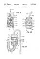
- FIG. 1is a schematic cross-sectional view showing one embodiment of a delay unit of the present invention including an input transmission line and an output transmission tube attached thereto;
- FIG. 1Ais a view, enlarged relative to FIG. 1, of the low energy booster detonator of the delay unit of FIG. 1 and certain connections thereto;
- FIG. 1Bis a view, enlarged relative to FIG. 1, of the output detonator of the delay unit of FIG. 1 and certain connections thereto;
- FIG. 2is a schematic block diagram representing the structure of the embodiment of FIG. 1;
- FIG. 3is a schematic cross-sectional view corresponding to that of FIG. 1 but with parts broken away, showing another embodiment of the delay unit of the present invention including an input transmission line attached thereto;
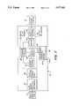
- FIG. 4is a schematic block diagram of one embodiment of a delay circuit utilizeable in accordance with the present invention, e.g., in the embodiments of FIGS. 1, 2 and 3;
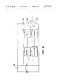
- FIG. 5is a schematic block diagram of another embodiment of a delay circuit utilizeable in accordance with the present invention, e.g., in the embodiments of FIGS. 1, 2 and 3.
- the signal delay units of the present inventionprovide accurate, electronically controlled delay periods. Although sometimes referred to as "in-line delay units", alluding to their use in blasting signal transmission lines, the signal delay units of the present invention may also be employed in conjunction with an instantaneous blasting cap to serve as a delay blasting cap, for example, in systems such as that of the aforementioned Spraggs et al U.S. Pat. No. 3,987,732. Thus, the signal delay units of the present invention find utility both as in-line delay units and as delay units for individual detonation caps. In certain embodiments of the present invention the delay period may be selected by the user by simple programming of the delay unit.
- a single delay unitmay be carried in stock to replace an entire inventory of preset in-line delay units provided by conventional pyrotechnic delay units.
- the provision of an electronic delay means by the delay units of the present inventioneliminates the need for pyrotechnic delay elements, and significantly reduces the amount of lead and delay chemical compounds .(which include suspected carcinogens) dispersed at blasting sites by the use of pyrotechnic delay units.
- FIG. 1shows one embodiment of an in-line delay unit 10 of the present invention.
- a housing 12which may be made of any suitable dielectric material such as a synthetic organic polymer (plastic), for example, polyethylene or other thermoplastic material, contains the other components of the in-line delay unit in suitable cavities formed in housing 12.
- Housing 12also serves to receive and connect the input and output transmission lines.
- the input transmission lineis provided by an input shock tube 14 and the output transmission line is provided by an output shock tube 16.
- a suitable inlet bore(unnumbered) is formed in housing 12 and receives and securely retains the input transmission shock tube 14, as described in more detail below.
- Input shock tube 14comprises a hollow plastic tube, the inner surface of which is coated by an explosive powder layer 14a (FIG. 1A). Input shock tube 14 terminates within housing 12 adjacent to a booster charge 26.
- Low energy booster detonator 18(FIGS. 1 and 1A) comprises a detonator shell 20, within which are disposed an anti-static cup 22, a first cushion element 24, and a booster charge 26.
- a transducerwhich, in the illustrated embodiment, comprises a piezoelectric generator 28, and a first conductor means which, in the illustrated embodiment, comprises a pair of leads 30a, 30b are mounted within housing 12 adjacent to low energy booster detonator 12.
- Detonator shell 20is crimped around a bushing 31 within which input shock tube 14 is received to help retain the end of the shock tube securely in place within low energy booster detonator 18.
- the one hundred eighty-degree return bend configuration of the inlet bore(FIG.
- booster charge 26is separated from anti-static cup 22 by first cushion element 24, the function of which is to distribute, during factory assembly of booster detonator 18, the pressure of a steel pin used to insert booster charge 26 into detonator shell 20. This distribution of pressure reduces the chance of detonation of booster charge 26 during the manufacturing process.
- First cushion element 24has a central aperture 24a formed therein and closed by a thin, rupturable membrane (unnumbered) to seal booster charge 26. Central aperture 24a provides a low-resistance path to booster charge 26 for the impulse signal delivered by input shock tube 14.
- Anti-static cup 22is made of a semi-conductive material such as a carbon-filled polymeric material and is in the shape of a truncated cone with a thin, rupturable membrane 22a extending across its midsection and against which the end of input shock tube 14 is seated, providing an air-gap "stand-off" between the end of input shock tube 14 and booster charge 26.
- Anti-static cup 22contacts the sides of detonator shell 20 and serves to ground any electrostatic discharge traveling through input shock tube 14 against shell 20 to eliminate the possibility of an electrostatic charge prematurely detonating booster charge 26.
- the use of such anti-static cup devicesis known in the art (see Gladden U.S. Pat. No. 3,981,240).
- a buffer 25is provided between the booster detonator shell 20 and piezoelectric generator 28.
- Buffer 25is a dielectric material and serves to electrically isolate piezoelectric generator 28 from detonator shell 20. Piezoelectric generator 28 is thus located in close proximity to booster charge 26 with only shell 20 and buffer 25 intervening between them.
- Piezoelectric generator 28comprises multiple alternating layers of a conductor and a piezoelectric ceramic wherein the metal layers are interconnected in parallel to form the output terminals (not shown) of piezoelectric generator 28.
- Leads 30a, 30bconnect the output terminals of piezoelectric generator 28 to a delay module provided in the illustrated embodiment by digital delay module 32 (FIGS. 1 and 2). Referring to FIG.
- digital delay module 32includes an energy storage capacitor 34, a trigger circuit 36, a delay circuit 38, and a programming interface means 42 mounted thereon.
- Energy storage capacitor 34is, in the illustrated embodiment, about a 3 micro-farad unit rated at 35 volts. Its series impedance is preferably low to accommodate the fast rise time of the 1 to 2 microsecond pulses generated by piezoelectric generator 28.
- the output of digital delay module 32is electrically connected by second conductor means to igniter element 46 of output detonator 48.
- the second conductor meanscomprise a pair of leads 44a, 44b, the ends of which are connected by a bridge wire 45 embedded within an igniter element 46 (FIG. 1B).
- output detonator 48comprises the igniter element 46 contained within an igniter cup 47 positioned within output detonator shell 50 in close proximity to an output charge 54. Leads 44a, 44b are retained within output detonator shell 50 by a bushing 51 held in place by the necked-down portion (unnumbered) of shell 50.
- a second cushion element 52 identical to first cushion element 24abuts and separates igniter element 46 from output charge 54.
- Cushion element 52contains a central aperture 52a which serves the same function as central aperture 24a of first cushion element 24 and is similarly closed with a thin, rupturable membrane (unnumbered) to seal output charge 54.
- the end of housing 12 adjacent to output detonator 48is configured to provide a plurality of output line retainer means for retaining one or more output transmission lines in proximity to output detonator 48.
- these output line retainer meansare provided by a combination of output line bores 56 and cleats 58.
- Output line bores 56have entry mouths 56a and exit mouths 56b.
- Cleats 58are generally hook-shaped, terminate in flexible lips 58a, and are located adjacent to and aligned with the exit mouths 56b of output line bores 56.
- Output line bores 56 and cleats 58thus cooperate to provide the output line retainer means in the illustrated embodiment.
- FIG. 1Only two such output line retainer means are illustrated in FIG. 1, it will be appreciated that more than two such output line retainer means could be provided. For example, in the illustrated embodiment, four or even six such output line retainer means could be evenly spaced about the periphery of housing 12.
- shock tube 16may be secured to housing 12 in close proximity to output detonator 48 by means of the output line retainer means provided by output line bores 56 and cleats 58.
- shock tube 16has a terminal end 16a which is closed and sealed against the environment by seal 16b which flattens and seals shock tube 16.
- a suitable detonator cap(not shown) is crimped onto the remote end (not shown) of shock tube 16 and may be emplaced within an explosive charge or may be utilized as a signal amplifying and transmitting cap to ignite another signal transmission tube to which it is connected.
- any suitable length of output shock tube 16may be employed and delay unit 10 may remain on the surface whether output shock tube 16 comprises a surface transmission line or a downhole line.
- delay unit 10may be placed within a borehole, e.g., when it is used in conjunction with an instantaneous blasting cap to provide an accurate delay period for a downhole blasting cap.
- a period tag 16cis attached near the terminal end 16a of shock tube 16 to indicate the delay period of the detonator cap (not shown) attached to the remote end (not shown) of shock tube 16.
- the legend "Period Zero" on period tag 16cindicates that the detonator cap attached to the remote end of shock tube 16 has no delay period, i.e., it is a zero period or instantaneous detonating cap.
- the detonator cap at the remote end of shock tube 16may, if desired, have an electronically controlled time delay period and such would be reflected in period tag 16c.
- a digital delay detonator cap of the type described in parent application Ser. No. 07/730,275would provide an accurate cap delay period.
- Shock tube 16is easily and securely attached to housing 12 by bending the tube back on itself a short distance away from terminal end 16a so as to form a loop or bight in shock tube 16, and forcing the bight of the tube upwardly into entry mouth 56a of bore 56 and out through exit mouth 56b to protrude beyond mouth 56b.
- the bightis advanced to protrude a distance sufficient to enable folding over of the shock tube to bring the bight thereof beneath the associated cleat 58 in the vicinity of the lip 58a thereof.
- the overlapping lengths of the shock tubeare then pulled downwardly in the direction of the unnumbered arrow in FIG.
- a programming interface means 42which may comprise any suitable electrical, optical or other programming interface means 42 is programmable from exteriorly of housing 12 and may be connected to digital delay module 32 by any suitable means represented by interface connector 62.
- a programming window 68is formed in housing 12 against which a suitable programming interface means 42 (not shown), such as a hand-held programmer, may be placed to carry out programming of delay unit 10 to provide a selected delay period for it.
- a guide-ridge 68ais formed about the periphery of programming window 68 to guide placement and retention of the programming interface means 42 in proper alignment with programming window 68.
- Interface connector 62may comprise any suitable connector means, e.g., soldered electrical wires, which, in the illustrated embodiment, serve to connect programming interface means 42 to digital delay module 32 to enable the entry of a specific time delay into delay module 32.
- the power necessary to perform this function and the programming signalcan be transferred by induction in a pick-up coil comprising part of programming interface means 42, in a well-known manner.
- programming interface means 42need not have any external pins or metallic conductive means requiring one or more physical openings in housing 12. This helps to assure the integrity of housing 12 and the contents thereof against environmental and stray electric field effects.
- a small battery having a long shelf lifesuch as a lithium battery, is provided to supply the power necessary for performing the programming function.
- the voltage and capacity of the batteryis chosen to ensure that the energy available from the battery is not sufficient to trigger igniter element 46 in case of a malfunction.
- housing 12is made of a nonconductive polymer that shields the internal components against both electrical signals and mechanical shocks that could inadvertently activate low energy booster detonator 18 or output detonator 48.
- conductive membersmay be encased within the walls of housing 12 to provide a high degree of attenuation of magnetic or electrical fields thereby protecting the internal circuitry, including the programming circuits, by forming a Faraday cage around the electrically sensitive components.
- housing 12may comprise a semi-conductive material to provide shielding for the circuitry components.
- Assembly of the componentsmay be carried out by encapsulating the components with potting compound within suitable recesses formed in housing 12, which may be generally cylindrical in configuration.
- the input transmission linesuch as shock tube 14 will be factory-installed and sealed within housing 12.
- the delay unit of the present inventionmay thus be provided with only a suitable length of shock tube 14 (or other suitable input transmission line) attached thereto.
- the connections to output transmission tubes, such as illustrated output shock tube 16may be made in the field as required.
- both input and output transmission linesmay be factory-installed or field-assembled.
- a cover(not shown in the drawings) may be provided for housing 12 to cover and seal the installed components.
- the covermay be secured in place by integral clips, ultrasonic welding, solvent bonding, ultrasonic staking, or an adhesive in order to provide a moisture-tight enclosure protected from the environment.
- FIGS. 1, 2 and 4the latter Figure showing details of one embodiment of the circuitry of delay module 32.
- Ignition of the input shock tube 14delivers an impulse signal which ruptures the membrane of anti-static cup 22 and first cushion element 24 to impact upon booster charge 26 and detonate it.
- Piezoelectric generator 28converts the shock energy delivered to it by the detonation of booster charge 26 into electrical energy which is delivered to digital delay module 32 via leads 30a, 30b.
- Digital delay module 32stores the electrical energy delivered to it from piezoelectric generator 28 in capacitor 34.
- piezoelectric generator 28 and energy storage capacitor 34respectively, comprise the transducer and energy storage means which together comprise the signal conversion means of the present invention.
- the electrical energy stored in capacitor 34is used in one embodiment for two purposes: the powering of the electronic timing of the digital delay module 32 and, after the preset time delay, the ignition of igniter element 46. More specifically, when the voltage of the electrical energy stored in capacitor 34 is above a selected threshhold, the logic and timer portion of the delay module 32 (FIG. 2) is energized.
- the first electric signal generated by piezoelectric generator 28is transmitted through steering diode 66 to capacitor 34, which stores the electrical energy.
- voltage regulator 77is activated to apply a portion only of the power generated by piezoelectric generator 28 to the timing circuits of oscillator 78, counter 80, and power-on reset circuit 82.
- a silicon controlled rectifier (“SCR") 84is activated by counter 80 at the conclusion of the timing interval, thereby supplying the remaining energy in capacitor 34 to the second conductor means provided, in the illustrated embodiment, by leads 44a, 44b.
- the power-on reset circuit 82preloads the counter 80 with count information from interface connector 62 (FIGS. 1 and 2) or, in an embodiment of the invention (not illustrated) which does not include a programming interface means such as programming interface means 42, preloads the counter with an initial preset count value. This preloading occurs at the time capacitor 34 receives the electrical signal from piezoelectric generator 28. Concurrently, oscillator 78 starts generating pulses (or cycles) that are counted by counter 80. As the counter 80, activated by the pulses from oscillator 78, reaches a preselected count as, for example, 1, the preprogrammed delay period expires and an activation signal is sent to SCR 84.
- the activation signalputs SCR 84 in a conducting state which allows it to conduct the electrical energy in capacitor 34 to leads 44a, 44b and bridge wire 45 which, in the illustrated embodiment, provide the second conductor means which serve to detonate igniter element 46 and thereby detonate output charge 54 (FIG. 1B) which, in turn, ignites the shock tube(s) 16 retained in proximity to detonator 48.
- the arrival at SCR 84 from capacitor 34 of the energy needed to detonate output charge 54is seen to be delayed by an interval essentially equal to the time required for the counter 80 to count the pulses from oscillator 78 from the initially preset amount from power-on reset circuit 82, to some value, for example, 1.
- a batterymay be included in the circuit to supply energy for programming the time delay.
- the battery energymay also be used not only for programming the time delay, but also for powering the delay circuits.
- ignition of the output charge(item 54 in the embodiment illustrated in FIG. 1B) is powered by energy emitted from the transducer (piezoelectric generator 28 in the embodiment illustrated in FIG. 1A) and not by battery or other stored energy sources.
- the battery or other stored energy source utilizedis of insufficient power to detonate the output charge.
- the piezoelectric generatoris designed to be actuated substantially only by the impulse signal imposed upon it by detonation of the booster charge (item 26 in the embodiment illustrated in FIG. 1A) or the detonating cord, described below in connection with the embodiment of FIG. 3.
- the transducere.g., the piezoelectric generator 28
- the transducerwill generate electric power sufficient to ignite the igniter element (item 46 in the embodiment illustrated in FIG. 1B) and thereby ignite the output charge (item 54 in the embodiment of FIG. 1B) to generate the outgoing signal substantially only by the input impulse signal or the amplification thereof by the booster charge (item 26 in the embodiment of FIG. 1A).
- the delay circuitsare powered by a source, e.g., a battery, connected therethrough through a silicon controlled rectifier (SCR) switch which is activated by a signal derived from the energy output of the piezoelectric generator.
- SCRsilicon controlled rectifier
- FIG. 5An embodiment of the invention illustrating the utilization of battery power for both programming the time delay and powering the delay circuits is illustrated in FIG. 5. The utilization of battery power enables the provision of a much longer delay period than that which could be attained if the piezoelectric generator were the sole source of power.
- FIG. 5wherein items identical or substantially the same as those of the embodiment of FIG. 4 are identically numbered as in FIG. 4, except for the addition of a prime indicator thereto.
- the first electric signal generated by piezoelectric generator 28'is transmitted through steering diode 66 to capacitor 34', which stores the electrical energy.
- the voltage reached by capacitor 34'is divided by resistors 70 and 72 to activate a silicon controlled rectifier (SCR) 74.
- SCR 74causes the power from a battery 76 to be applied to the timing circuits of oscillator 78', counter 80', and power-on reset circuit 82'.
- SCR 84'is activated by counter 80' at the conclusion of the timing interval, thereby supplying energy to the second conductor means provided, in the illustrated embodiment, by leads 44a, 44b.
- Operation of the circuit of FIG. 5is substantially the same as that described above with respect to the circuit of FIG. 4 except that, as noted above, the power for programming the time delay and powering the delay circuits is provided by the battery 76 and the power output of piezoelectric generator 28' is needed only to initiate the timing and detonate the output charge 54.
- FIG. 2diagramatically shows input shock tube 14 for delivering a pressure input pulse to low energy booster detonator 18 which detonates to provide the amplified signal used to generate a pressure pulse on piezoelectric generator 28.
- Energy storage capacitor 34, trigger circuit 36 and delay circuit 38are part of digital delay module 32.
- Piezoelectric generator 28generates the first electric signal pulse in response to the pressure imposed on it from low energy booster detonator 18. This first electric signal is stored in an energy storage capacitor 34 to be subsequently used by trigger circuit 36 and delay circuit 38.
- Delay circuit 38activates trigger circuit 36 after the time interval programmed into delay circuit 38 has elapsed.
- Trigger circuit 36allows electrical energy stored in energy storage capacitor 34 to flow to igniter element 46, thereby triggering output charge 54 to generate a pressure output pulse large enough to initiate one or more output transmission lines such as shock tube(s) 16 which are retained in close proximity to output charge 54.
- Delay circuit 38communicates through interface connector 62 and programming interface means 42 with any suitable external means (not shown) placed against programming window 68 and oriented thereagainst by guideridge 68a (FIGS. 1 and 2).
- the signals from the external programmer meansare encoded by any suitable well-known techniques to both power and pass delay information to delay circuit 38 via interface means 42 and interface connector 62.
- an infra red emitter 60a and receiver 60bare shown in FIG. 1 as the means to provide communication between the external programmer means and interface means 42.
- FIG. 3shows another embodiment of the present invention in which items similar to those of the embodiment of FIGS. 1 and 2 are identically numbered to those of FIG. 1 but with the addition of a prime indicator. Identical components are identically numbered.
- the input transmission line connected to delay unit 10'is provided by a low energy detonating cord 14', which is used in lieu of input shock tube 14 and booster charge 26 of the embodiment of FIGS. 1 and 2.
- detonating cord 14'is mounted in housing 12 in the same manner as shock tube 14 of the FIG. 1 embodiment, but terminates in opposite-facing proximity to piezoelectric generator 28 within a chamber 15 defined by detonator shell 20'.
- the impulse input signal required to activate the piezoelectric generatoris provided in this embodiment directly by low power detonating cord 14'.
- the low power detonating cordhas a solid explosive core 14a' of sufficiently low explosive power to ensure the preservation of the integrity of the housing 12 of the in-line delay unit 10'. Nonetheless, detonating cord 14' has sufficient explosive power to directly excite the piezoelectric generator 28 to produce electrical energy sufficient to generate the electric signal needed to detonate the output charge (not shown in FIG. 3).
- Piezoelectric generator 28responds to the input impulse signal provided by the explosion shock wave generated by detonation of low power detonating cord 14' by generating electrical energy that is stored in energy storage capacitor 34 (not shown in FIG. 3). All the components of the embodiment of FIG. 3 other than as specifically set forth above, are identical to those illustrated in FIG. 1 and function in exactly the same manner. Therefore, it is not necessary to illustrate them in FIG. 3 or to repeat the description of their function.
- the present inventionthus provides an accurate time delay between an impulse input signal (flame front, pressure wave, explosion, etc.), i.e., a non-electric signal, carried by an input transmission line and an output impulse signal transmitted by one or more output transmission lines to, e.g., each borehole in a group of multiple boreholes.
- an impulse input signalflame front, pressure wave, explosion, etc.
- a non-electric signalcarried by an input transmission line
- an output impulse signal transmitted by one or more output transmission linesto, e.g., each borehole in a group of multiple boreholes.
- the present inventionprovides for a field programmable delay detonator, adjustable in small time increments, thereby requiring only a single type of in-line delay unit to be kept in stock and used for the implementation of different in-line delays at a blasting site.
Landscapes
- Engineering & Computer Science (AREA)
- General Engineering & Computer Science (AREA)
- Chemical & Material Sciences (AREA)
- Crystallography & Structural Chemistry (AREA)
- Computer Hardware Design (AREA)
- Microelectronics & Electronic Packaging (AREA)
- Air Bags (AREA)
Abstract
Description
Claims (29)
Priority Applications (2)
| Application Number | Priority Date | Filing Date | Title |
|---|---|---|---|
| US07/949,466US5377592A (en) | 1991-07-09 | 1992-09-22 | Impulse signal delay unit |
| US07/994,676US5435248A (en) | 1991-07-09 | 1992-12-22 | Extended range digital delay detonator |
Applications Claiming Priority (2)
| Application Number | Priority Date | Filing Date | Title |
|---|---|---|---|
| US07/730,275US5173569A (en) | 1991-07-09 | 1991-07-09 | Digital delay detonator |
| US07/949,466US5377592A (en) | 1991-07-09 | 1992-09-22 | Impulse signal delay unit |
Related Parent Applications (1)
| Application Number | Title | Priority Date | Filing Date |
|---|---|---|---|
| US07/730,275Continuation-In-PartUS5173569A (en) | 1991-07-09 | 1991-07-09 | Digital delay detonator |
Related Child Applications (1)
| Application Number | Title | Priority Date | Filing Date |
|---|---|---|---|
| US07/994,676Continuation-In-PartUS5435248A (en) | 1991-07-09 | 1992-12-22 | Extended range digital delay detonator |
Publications (1)
| Publication Number | Publication Date |
|---|---|
| US5377592Atrue US5377592A (en) | 1995-01-03 |
Family
ID=24934662
Family Applications (2)
| Application Number | Title | Priority Date | Filing Date |
|---|---|---|---|
| US07/730,275Expired - LifetimeUS5173569A (en) | 1991-07-09 | 1991-07-09 | Digital delay detonator |
| US07/949,466Expired - LifetimeUS5377592A (en) | 1991-07-09 | 1992-09-22 | Impulse signal delay unit |
Family Applications Before (1)
| Application Number | Title | Priority Date | Filing Date |
|---|---|---|---|
| US07/730,275Expired - LifetimeUS5173569A (en) | 1991-07-09 | 1991-07-09 | Digital delay detonator |
Country Status (10)
| Country | Link |
|---|---|
| US (2) | US5173569A (en) |
| JP (1) | JP2541727B2 (en) |
| AU (1) | AU645731B2 (en) |
| BR (1) | BR9202520A (en) |
| CA (1) | CA2067661C (en) |
| DE (1) | DE4218881C2 (en) |
| GB (1) | GB2257776B (en) |
| MX (1) | MX9202887A (en) |
| SE (1) | SE511798C2 (en) |
| ZA (1) | ZA923389B (en) |
Cited By (42)
| Publication number | Priority date | Publication date | Assignee | Title |
|---|---|---|---|---|
| WO1995020746A1 (en)* | 1994-01-27 | 1995-08-03 | Tpp Technological Industries Ltd. | Autonomous electric detonator |
| EP0677164A4 (en)* | 1992-12-22 | 1996-04-10 | Ensign Bickford Co | Digital delay unit. |
| US5507230A (en)* | 1993-10-22 | 1996-04-16 | Universal Propulsion Company, Inc. | Self-powered delayed ordnance |
| US5614693A (en)* | 1996-01-11 | 1997-03-25 | The Ensign-Bickford Company | Accessory charges for booster explosive devices |
| WO1997025298A1 (en)* | 1996-01-11 | 1997-07-17 | The Ensign-Bickford Company | Detonators having multiple-line input leads |
| WO1997026232A1 (en)* | 1996-01-16 | 1997-07-24 | The Ensign-Bickford Company | Slider member for booster explosive charges |
| US5703320A (en)* | 1996-01-18 | 1997-12-30 | The Ensign Bickford Company | Connector for blast initiation system |
| US5708228A (en)* | 1996-01-11 | 1998-01-13 | The Ensign-Bickford Company | Method and apparatus for transfer of initiation signals |
| WO1998022774A2 (en) | 1996-11-01 | 1998-05-28 | The Ensign-Bickford Company | Shock-resistant electronic circuit assembly |
| WO1998026248A1 (en) | 1996-12-09 | 1998-06-18 | The Ensign-Bickford Company | Hybrid electronic detonator delay circuit assembly |
| US5780764A (en)* | 1996-01-11 | 1998-07-14 | The Ensign-Bickford Company | Booster explosive devices and combinations thereof with explosive accessory charges |
| WO1998058228A1 (en) | 1997-06-19 | 1998-12-23 | The Ensign-Bickford Company | Electronic circuitry for timing and delay circuits |
| US6082264A (en)* | 1996-12-19 | 2000-07-04 | Sasol Mining Initiators (Proprietary) Limited | Connectors for wired networks for detonators |
| EP1106956A1 (en) | 1999-12-06 | 2001-06-13 | The Ensign Bickford Company | Shock-resistant electronic circuit assembly |
| US6386085B1 (en)* | 1998-12-24 | 2002-05-14 | Betty A. Garrett | Method and apparatus for explosives assembly |
| US20040031411A1 (en)* | 2002-06-12 | 2004-02-19 | Novotney David B. | Signal transfer device |
| US20060124018A1 (en)* | 2002-11-08 | 2006-06-15 | Graham John A | Explosive-activated safe-arm device |
| US20080245254A1 (en)* | 2004-06-22 | 2008-10-09 | Orica Explosives Technology Pty Ltd | Method Of Blasting |
| US20080282925A1 (en)* | 2007-05-15 | 2008-11-20 | Orica Explosives Technology Pty Ltd | Electronic blasting with high accuracy |
| US20110155012A1 (en)* | 2009-12-30 | 2011-06-30 | Pio Francisco Perez Cordova | Detonator system with high precision delay |
| US8161877B1 (en)* | 2005-12-07 | 2012-04-24 | The United States Of America As Represented By The United States Department Of Energy | Electronic firing systems and methods for firing a device |
| US20120180681A1 (en)* | 2007-07-10 | 2012-07-19 | Omnitek Partners Llc | Inertially Operated Electrical Initiation Methods |
| US20120180682A1 (en)* | 2007-07-10 | 2012-07-19 | Omnitek Partners Llc | Inertially Operated Electrical Initiation Devices |
| US20120180680A1 (en)* | 2007-07-10 | 2012-07-19 | Omnitek Partners Llc | Inertially Operated Electrical Initiation Devices |
| US20120210896A1 (en)* | 2007-07-10 | 2012-08-23 | Omnitek Partners Llc | Electrically Initiated Inertial Igniters for Thermal Batteries and the Like |
| US8286554B2 (en)* | 2007-07-10 | 2012-10-16 | Omnitek Partners Llc | Electrically initiated inertial igniters for thermal batteries and the like |
| US20130174754A1 (en)* | 2007-07-10 | 2013-07-11 | Omnitek Partners Llc | Inertially Operated Electrical Initiation Devices |
| US20130174756A1 (en)* | 2007-07-10 | 2013-07-11 | Omnitek Partners Llc | Inertially Operated Electrical Initiation Devices |
| US20130180423A1 (en)* | 2007-07-10 | 2013-07-18 | Omnitek Partners Llc | Shock Detection Circuit and Method of Shock Detection |
| US20130277108A1 (en)* | 2012-04-24 | 2013-10-24 | Fike Corporation | Energy transfer device |
| US20140060366A1 (en)* | 2007-07-10 | 2014-03-06 | Omnitek Partners Llc | Inertially Operated Electrical Initiation Devices |
| US8701560B2 (en) | 2010-11-22 | 2014-04-22 | Battelle Energy Alliance, Llc | Apparatus, system, and method for synchronizing a timer key |
| US20140202350A1 (en)* | 2007-07-10 | 2014-07-24 | Omnitek Partners Llc | Inertially Operated Piezoelectric Energy Harvesting Electronic Circuitry |
| US8919253B2 (en) | 2011-05-26 | 2014-12-30 | Baker Hughes Incorporated | Perforating string with magnetohydrodynamic initiation transfer |
| US20150331008A1 (en)* | 2007-07-10 | 2015-11-19 | Omnitek Partners Llc | Piezoelectric-Based Multiple Impact Sensors and Their Electronic Circuitry |
| CN105403112A (en)* | 2015-11-05 | 2016-03-16 | 张国荣 | Detonating tube electronic delay detonator and method for detonating detonator under double control of light and shock waves |
| US20170133954A1 (en)* | 2007-07-10 | 2017-05-11 | Omnitek Partners Llc | Manually Operated Piezoelectric Energy Harvesting Electronic Circuitry |
| US9921041B1 (en) | 2015-09-29 | 2018-03-20 | The United States Of America As Represented By The Secretary Of The Navy | Primerless digital time-delay initiator system |
| US20190003810A1 (en)* | 2008-06-29 | 2019-01-03 | Omnitek Partners Llc | Inertially Operated Piezoelectric Energy Harvesting Electronic Circuitry |
| US10447179B2 (en)* | 2007-07-10 | 2019-10-15 | Omnitek Partners Llc | Inertially operated piezoelectric energy harvesting electronic circuitry |
| US11248893B2 (en)* | 2008-06-29 | 2022-02-15 | Omnitek Partners Llc | Inertially operated piezoelectric energy harvesting electronic circuitry |
| RU2818963C1 (en)* | 2023-11-17 | 2024-05-08 | Акционерное общество "Концерн воздушно-космической обороны "Алмаз - Антей" | Self-contained generator of powerful pulses of microwave oscillations |
Families Citing this family (35)
| Publication number | Priority date | Publication date | Assignee | Title |
|---|---|---|---|---|
| US5173569A (en)* | 1991-07-09 | 1992-12-22 | The Ensign-Bickford Company | Digital delay detonator |
| US5440990A (en)* | 1993-09-16 | 1995-08-15 | The Walt Disney Company | Electronic time fuze |
| DE4427296A1 (en)* | 1994-08-02 | 1996-02-08 | Dynamit Nobel Ag | Non-electric detonator |
| US5621184A (en) | 1995-04-10 | 1997-04-15 | The Ensign-Bickford Company | Programmable electronic timer circuit |
| BR9502995A (en)* | 1995-06-23 | 1997-09-23 | Ibq Ind Quimicas Ltda | Electronic delay detonator |
| US5831203A (en)* | 1997-03-07 | 1998-11-03 | The Ensign-Bickford Company | High impedance semiconductor bridge detonator |
| US5889228A (en)* | 1997-04-09 | 1999-03-30 | The Ensign-Bickford Company | Detonator with loosely packed ignition charge and method of assembly |
| AU2285900A (en)* | 1999-01-08 | 2000-07-24 | Dynamit Nobel Gmbh Explosivstoff- Und Systemtechnik | Control module for triggering units for initiating pyrotechnical elements |
| US20100251879A1 (en)* | 2006-01-17 | 2010-10-07 | Rastegar Jahangir S | Energy harvesting power sources for assisting in the recovery/detonation of unexploded munitions governmental rights |
| US7778006B2 (en)* | 2006-04-28 | 2010-08-17 | Orica Explosives Technology Pty Ltd. | Wireless electronic booster, and methods of blasting |
| ES2566534T3 (en)* | 2008-11-05 | 2016-04-13 | Saab Ab | A power and delay circuit |
| FR2959809B1 (en)* | 2010-05-10 | 2013-07-05 | Saint Louis Inst | FIRING DEVICE FOR AN INITIATOR |
| AU2011278960B2 (en)* | 2010-07-12 | 2015-02-05 | Detnet South Africa (Pty) Ltd | Timing module |
| AU2015201933B2 (en)* | 2010-07-12 | 2016-08-04 | Detnet South Africa (Pty) Ltd | Timing module |
| US10527395B2 (en) | 2010-07-12 | 2020-01-07 | Detnet South Africa (Pty) Ltd | Detonator |
| PE20130595A1 (en)* | 2011-10-14 | 2013-05-09 | Famesa Explosivos S A C | SIGNAL TRANSMISSION TUBE WITH REVERSE INITIATION RETENTION SEAL |
| RU2497797C2 (en)* | 2011-12-30 | 2013-11-10 | Открытое акционерное общество Новосибирский механический завод "Искра" | Detonator with electronic delay for shock-wave tube (swt) |
| US20130205888A1 (en)* | 2012-02-10 | 2013-08-15 | Austin Powder Company | Method and apparatus to measure borehole pressure during blasting |
| US10006281B2 (en) | 2012-02-10 | 2018-06-26 | Austin Star Detonator Company | Calibration of molded piezoelectric longitudinal charge coefficient of a pressure sensor for blasting operation |
| CN104481469B (en)* | 2014-09-29 | 2017-08-25 | 殷婷 | Multi-stage ignition exploding perforating hole system based on the digital electric detonator using single-core cable |
| CN104501666B (en)* | 2014-11-27 | 2017-01-18 | 安徽理工大学 | High-precision safe-type delay element |
| EP3076120A1 (en)* | 2015-03-30 | 2016-10-05 | Maxamcorp Holding, S.L. | Protection circuit in blasting systems |
| WO2016171581A1 (en)* | 2015-04-24 | 2016-10-27 | САЯПИН, Виталий Викторович | Blasting cap |
| ES2794097T3 (en)* | 2015-12-02 | 2020-11-17 | Mas Zengrange Nz Ltd | Maritime flotation device |
| WO2017210442A1 (en)* | 2016-06-03 | 2017-12-07 | Fike Corporation | Floating oil spill ignition device |
| RU2642696C1 (en)* | 2016-10-10 | 2018-01-25 | Владимир Викторович Черниченко | Contact target sensor |
| RU2689357C1 (en)* | 2018-07-02 | 2019-05-27 | Федеральное государственное унитарное предприятие "Российский федеральный ядерный центр - Всероссийский научно-исследовательский институт технической физики имени академика Е.И. Забабахина" | Programmable detonator |
| US10816311B2 (en) | 2018-11-07 | 2020-10-27 | DynaEnergetics Europe GmbH | Electronic time delay fuse |
| AU2020216554B2 (en)* | 2019-01-28 | 2024-12-19 | Detnet South Africa (Pty) Ltd | Detonator construction |
| RU195248U1 (en)* | 2019-03-29 | 2020-01-21 | ООО КТБ "Интервал" | DETONATOR CAPSULE |
| CN111559502B (en)* | 2020-05-26 | 2022-01-28 | 中国人民解放军32181部队 | Unmanned aerial vehicle throwing type energy-gathering destroying equipment and destroying method |
| WO2022203528A1 (en)* | 2021-03-25 | 2022-09-29 | Arancibia Vasquez Arnaldo Ignacio | Electronic adapter with programmed delay for igniting a primer |
| US20240209704A1 (en)* | 2022-12-22 | 2024-06-27 | Dbk Industries, Llc | Direct-to-Gun Setting Tool |
| US20240218755A1 (en)* | 2022-12-28 | 2024-07-04 | Dbk Industries, Llc | Electric Igniter for Downhole Settings Tools |
| CN116518802B (en)* | 2023-05-15 | 2025-10-03 | 武汉理工大学 | A device and method for quasi-explosive firing of a nonel electronic detonator |
Citations (27)
| Publication number | Priority date | Publication date | Assignee | Title |
|---|---|---|---|---|
| US3340811A (en)* | 1966-05-20 | 1967-09-12 | Avco Corp | Piezoelectric delayed squib initiator |
| US3610153A (en)* | 1969-01-08 | 1971-10-05 | Us Army | Self-contained delay squib |
| DE2206640A1 (en)* | 1971-02-15 | 1972-08-24 | Etablissements Boubiela, Saint-Quentin (Frankreich) | Device for automatic loading of pallets with sacks |
| US3741124A (en)* | 1971-05-11 | 1973-06-26 | Us Navy | Demolition firing device |
| US3885501A (en)* | 1973-11-16 | 1975-05-27 | Calspan Corp | Fail-safe electrical timer |
| US3981240A (en)* | 1975-07-30 | 1976-09-21 | The Ensign-Bickford Company | Detonating cap assembly and connecting bushing |
| US3987729A (en)* | 1973-10-31 | 1976-10-26 | Imperial Chemical Industries Limited | Device for firing an electric detonator |
| US3987732A (en)* | 1975-02-10 | 1976-10-26 | The Ensign-Bickford Company | Non-electric double delay borehole downline unit for blasting operations |
| US4328751A (en)* | 1980-05-05 | 1982-05-11 | Atlas Powder Company | Electronic delay blasting circuit |
| US4393779A (en)* | 1977-10-20 | 1983-07-19 | Dynamit Nobel Aktiengesellschaft | Electric detonator element |
| US4395950A (en)* | 1980-05-05 | 1983-08-02 | Atlas Powder Company | Electronic delay blasting circuit |
| ZA836416B (en)* | 1982-09-21 | 1984-04-25 | Continental Gummi Werke Ag | Pneumatic vehicle tyre |
| US4445435A (en)* | 1980-05-05 | 1984-05-01 | Atlas Powder Company | Electronic delay blasting circuit |
| US4481884A (en)* | 1981-12-28 | 1984-11-13 | E. I. Du Pont De Nemours And Company | Field-connected explosive booster for initiating low-energy explosive connecting cords |
| US4607573A (en)* | 1984-04-03 | 1986-08-26 | Ensign-Bickford Industries, Inc. | Laminated fuse and manufacturing process therefor |
| US4617866A (en)* | 1983-05-18 | 1986-10-21 | Haley & Weller Limited | Pyrotechnic or explosive device |
| US4632031A (en)* | 1983-04-11 | 1986-12-30 | The Commonwealth Of Australia | Programmable electronic delay fuse |
| US4674047A (en)* | 1984-01-31 | 1987-06-16 | The Curators Of The University Of Missouri | Integrated detonator delay circuits and firing console |
| US4730556A (en)* | 1985-10-28 | 1988-03-15 | Nordson Corporation | Method of screen printing with hot melt foam compositions |
| US4742773A (en)* | 1986-10-03 | 1988-05-10 | The Ensign-Bickford Company | Blasting signal transmission tube delay unit |
| US4757764A (en)* | 1985-12-20 | 1988-07-19 | The Ensign-Bickford Company | Nonelectric blasting initiation signal control system, method and transmission device therefor |
| WO1989001601A1 (en)* | 1987-08-14 | 1989-02-23 | Bert Jonsson | An ignition system and a method for the initiation thereof |
| ZA896936B (en)* | 1988-09-12 | 1990-05-30 | Plessey South Africa | Timing of a multi-shot blast |
| ZA896536B (en)* | 1988-08-29 | 1990-05-30 | Expert Explosives | Detonator |
| AU6708090A (en)* | 1989-12-14 | 1991-06-20 | Arthur George Yarrington | Electrical optical detonator |
| WO1992000498A1 (en)* | 1990-07-02 | 1992-01-09 | Explodet Ab | Piezoelectrical igniter |
| US5173569A (en)* | 1991-07-09 | 1992-12-22 | The Ensign-Bickford Company | Digital delay detonator |
Family Cites Families (12)
| Publication number | Priority date | Publication date | Assignee | Title |
|---|---|---|---|---|
| US3320890A (en)* | 1965-05-06 | 1967-05-23 | Thomas Q Ciccone | Piezo-electric detonation initiator system |
| FR2142634B2 (en)* | 1971-02-11 | 1973-05-25 | Lacroix | |
| JPS49120499A (en)* | 1973-03-20 | 1974-11-18 | ||
| DE2314709A1 (en)* | 1973-03-24 | 1974-09-26 | Dynamit Nobel Ag | ELECTRIC IGNITION DEVICE |
| CH628423A5 (en)* | 1978-09-05 | 1982-02-26 | Prb Sa | ELECTRICAL CIRCUIT FOR THE IGNITION OF A DETONATOR. |
| US4311096A (en)* | 1980-05-05 | 1982-01-19 | Atlas Powder Company | Electronic blasting cap |
| US4586437A (en)* | 1984-04-18 | 1986-05-06 | Asahi Kasei Kogyo Kabushiki Kaisha | Electronic delay detonator |
| DE8432097U1 (en)* | 1984-11-02 | 1986-07-17 | Dynamit Nobel Ag, 5210 Troisdorf | Electronic time detonator |
| ZA872933B (en)* | 1986-04-26 | 1987-10-19 | Dynamit Nobel Aktiengesellschaft | Explosive delay detonator |
| IT1191814B (en)* | 1986-06-27 | 1988-03-23 | Brown Boveri Tecnomasio Ital | SWITCHING CIRCUIT OF THE NUMBER OF POLES ON THE SYNCHRONOUS MACHINE ROTOR USING ROTARY DIODES |
| US5031538A (en)* | 1990-02-07 | 1991-07-16 | The Ensign-Bickford Company | Delay train ignition buffer |
| US5293821A (en)* | 1990-06-22 | 1994-03-15 | Ici Canada Inc. | Delay initiator for blasting |
- 1991
- 1991-07-09USUS07/730,275patent/US5173569A/ennot_activeExpired - Lifetime
- 1992
- 1992-04-23AUAU15098/92Apatent/AU645731B2/ennot_activeExpired
- 1992-04-30CACA002067661Apatent/CA2067661C/ennot_activeExpired - Lifetime
- 1992-05-11ZAZA923389Apatent/ZA923389B/enunknown
- 1992-05-21GBGB9210836Apatent/GB2257776B/ennot_activeExpired - Fee Related
- 1992-06-09DEDE4218881Apatent/DE4218881C2/ennot_activeExpired - Fee Related
- 1992-06-15MXMX9202887Apatent/MX9202887A/enunknown
- 1992-06-25JPJP4167825Apatent/JP2541727B2/ennot_activeExpired - Fee Related
- 1992-07-08BRBR929202520Apatent/BR9202520A/ennot_activeIP Right Cessation
- 1992-07-08SESE9202119Apatent/SE511798C2/ennot_activeIP Right Cessation
- 1992-09-22USUS07/949,466patent/US5377592A/ennot_activeExpired - Lifetime
Patent Citations (27)
| Publication number | Priority date | Publication date | Assignee | Title |
|---|---|---|---|---|
| US3340811A (en)* | 1966-05-20 | 1967-09-12 | Avco Corp | Piezoelectric delayed squib initiator |
| US3610153A (en)* | 1969-01-08 | 1971-10-05 | Us Army | Self-contained delay squib |
| DE2206640A1 (en)* | 1971-02-15 | 1972-08-24 | Etablissements Boubiela, Saint-Quentin (Frankreich) | Device for automatic loading of pallets with sacks |
| US3741124A (en)* | 1971-05-11 | 1973-06-26 | Us Navy | Demolition firing device |
| US3987729A (en)* | 1973-10-31 | 1976-10-26 | Imperial Chemical Industries Limited | Device for firing an electric detonator |
| US3885501A (en)* | 1973-11-16 | 1975-05-27 | Calspan Corp | Fail-safe electrical timer |
| US3987732A (en)* | 1975-02-10 | 1976-10-26 | The Ensign-Bickford Company | Non-electric double delay borehole downline unit for blasting operations |
| US3981240A (en)* | 1975-07-30 | 1976-09-21 | The Ensign-Bickford Company | Detonating cap assembly and connecting bushing |
| US4393779A (en)* | 1977-10-20 | 1983-07-19 | Dynamit Nobel Aktiengesellschaft | Electric detonator element |
| US4445435A (en)* | 1980-05-05 | 1984-05-01 | Atlas Powder Company | Electronic delay blasting circuit |
| US4395950A (en)* | 1980-05-05 | 1983-08-02 | Atlas Powder Company | Electronic delay blasting circuit |
| US4328751A (en)* | 1980-05-05 | 1982-05-11 | Atlas Powder Company | Electronic delay blasting circuit |
| US4481884A (en)* | 1981-12-28 | 1984-11-13 | E. I. Du Pont De Nemours And Company | Field-connected explosive booster for initiating low-energy explosive connecting cords |
| ZA836416B (en)* | 1982-09-21 | 1984-04-25 | Continental Gummi Werke Ag | Pneumatic vehicle tyre |
| US4632031A (en)* | 1983-04-11 | 1986-12-30 | The Commonwealth Of Australia | Programmable electronic delay fuse |
| US4617866A (en)* | 1983-05-18 | 1986-10-21 | Haley & Weller Limited | Pyrotechnic or explosive device |
| US4674047A (en)* | 1984-01-31 | 1987-06-16 | The Curators Of The University Of Missouri | Integrated detonator delay circuits and firing console |
| US4607573A (en)* | 1984-04-03 | 1986-08-26 | Ensign-Bickford Industries, Inc. | Laminated fuse and manufacturing process therefor |
| US4730556A (en)* | 1985-10-28 | 1988-03-15 | Nordson Corporation | Method of screen printing with hot melt foam compositions |
| US4757764A (en)* | 1985-12-20 | 1988-07-19 | The Ensign-Bickford Company | Nonelectric blasting initiation signal control system, method and transmission device therefor |
| US4742773A (en)* | 1986-10-03 | 1988-05-10 | The Ensign-Bickford Company | Blasting signal transmission tube delay unit |
| WO1989001601A1 (en)* | 1987-08-14 | 1989-02-23 | Bert Jonsson | An ignition system and a method for the initiation thereof |
| ZA896536B (en)* | 1988-08-29 | 1990-05-30 | Expert Explosives | Detonator |
| ZA896936B (en)* | 1988-09-12 | 1990-05-30 | Plessey South Africa | Timing of a multi-shot blast |
| AU6708090A (en)* | 1989-12-14 | 1991-06-20 | Arthur George Yarrington | Electrical optical detonator |
| WO1992000498A1 (en)* | 1990-07-02 | 1992-01-09 | Explodet Ab | Piezoelectrical igniter |
| US5173569A (en)* | 1991-07-09 | 1992-12-22 | The Ensign-Bickford Company | Digital delay detonator |
Cited By (71)
| Publication number | Priority date | Publication date | Assignee | Title |
|---|---|---|---|---|
| EP0677164A4 (en)* | 1992-12-22 | 1996-04-10 | Ensign Bickford Co | Digital delay unit. |
| US5507230A (en)* | 1993-10-22 | 1996-04-16 | Universal Propulsion Company, Inc. | Self-powered delayed ordnance |
| WO1995020746A1 (en)* | 1994-01-27 | 1995-08-03 | Tpp Technological Industries Ltd. | Autonomous electric detonator |
| US5708228A (en)* | 1996-01-11 | 1998-01-13 | The Ensign-Bickford Company | Method and apparatus for transfer of initiation signals |
| US5780764A (en)* | 1996-01-11 | 1998-07-14 | The Ensign-Bickford Company | Booster explosive devices and combinations thereof with explosive accessory charges |
| WO1997025298A1 (en)* | 1996-01-11 | 1997-07-17 | The Ensign-Bickford Company | Detonators having multiple-line input leads |
| US5614693A (en)* | 1996-01-11 | 1997-03-25 | The Ensign-Bickford Company | Accessory charges for booster explosive devices |
| US5747722A (en)* | 1996-01-11 | 1998-05-05 | The Ensign-Bickford Company | Detonators having multiple-line input leads |
| WO1997026232A1 (en)* | 1996-01-16 | 1997-07-24 | The Ensign-Bickford Company | Slider member for booster explosive charges |
| US5661256A (en)* | 1996-01-16 | 1997-08-26 | The Ensign-Bickford Company | Slider member for booster explosive charges |
| US5703320A (en)* | 1996-01-18 | 1997-12-30 | The Ensign Bickford Company | Connector for blast initiation system |
| WO1998022774A2 (en) | 1996-11-01 | 1998-05-28 | The Ensign-Bickford Company | Shock-resistant electronic circuit assembly |
| US6311621B1 (en)* | 1996-11-01 | 2001-11-06 | The Ensign-Bickford Company | Shock-resistant electronic circuit assembly |
| US6079332A (en)* | 1996-11-01 | 2000-06-27 | The Ensign-Bickford Company | Shock-resistant electronic circuit assembly |
| WO1998026248A1 (en) | 1996-12-09 | 1998-06-18 | The Ensign-Bickford Company | Hybrid electronic detonator delay circuit assembly |
| US5929368A (en)* | 1996-12-09 | 1999-07-27 | The Ensign-Bickford Company | Hybrid electronic detonator delay circuit assembly |
| US6082264A (en)* | 1996-12-19 | 2000-07-04 | Sasol Mining Initiators (Proprietary) Limited | Connectors for wired networks for detonators |
| US5912428A (en)* | 1997-06-19 | 1999-06-15 | The Ensign-Bickford Company | Electronic circuitry for timing and delay circuits |
| WO1998058228A1 (en) | 1997-06-19 | 1998-12-23 | The Ensign-Bickford Company | Electronic circuitry for timing and delay circuits |
| US6386085B1 (en)* | 1998-12-24 | 2002-05-14 | Betty A. Garrett | Method and apparatus for explosives assembly |
| EP1106956A1 (en) | 1999-12-06 | 2001-06-13 | The Ensign Bickford Company | Shock-resistant electronic circuit assembly |
| US20040031411A1 (en)* | 2002-06-12 | 2004-02-19 | Novotney David B. | Signal transfer device |
| WO2003107542A3 (en)* | 2002-06-12 | 2004-10-21 | Ensign Bickford Aerospace & De | Signal transfer device |
| US20060124018A1 (en)* | 2002-11-08 | 2006-06-15 | Graham John A | Explosive-activated safe-arm device |
| US20080245254A1 (en)* | 2004-06-22 | 2008-10-09 | Orica Explosives Technology Pty Ltd | Method Of Blasting |
| US7707939B2 (en)* | 2004-06-22 | 2010-05-04 | Orica Explosives Technology Pty Ltd | Method of blasting |
| US8161877B1 (en)* | 2005-12-07 | 2012-04-24 | The United States Of America As Represented By The United States Department Of Energy | Electronic firing systems and methods for firing a device |
| US9046268B2 (en) | 2005-12-07 | 2015-06-02 | Battelle Energy Alliance | Methods for synchronizing a countdown routine of a timer key and electronic device |
| US20080282925A1 (en)* | 2007-05-15 | 2008-11-20 | Orica Explosives Technology Pty Ltd | Electronic blasting with high accuracy |
| US8286554B2 (en)* | 2007-07-10 | 2012-10-16 | Omnitek Partners Llc | Electrically initiated inertial igniters for thermal batteries and the like |
| US9021955B2 (en)* | 2007-07-10 | 2015-05-05 | Omnitek Partners Llc | Inertially operated electrical initiation devices |
| US20120180682A1 (en)* | 2007-07-10 | 2012-07-19 | Omnitek Partners Llc | Inertially Operated Electrical Initiation Devices |
| US20120180680A1 (en)* | 2007-07-10 | 2012-07-19 | Omnitek Partners Llc | Inertially Operated Electrical Initiation Devices |
| US20120210896A1 (en)* | 2007-07-10 | 2012-08-23 | Omnitek Partners Llc | Electrically Initiated Inertial Igniters for Thermal Batteries and the Like |
| US10581347B2 (en)* | 2007-07-10 | 2020-03-03 | Omnitek Partners Llc | Manually operated piezoelectric energy harvesting electronic circuitry |
| US10447179B2 (en)* | 2007-07-10 | 2019-10-15 | Omnitek Partners Llc | Inertially operated piezoelectric energy harvesting electronic circuitry |
| US20130174754A1 (en)* | 2007-07-10 | 2013-07-11 | Omnitek Partners Llc | Inertially Operated Electrical Initiation Devices |
| US20130174756A1 (en)* | 2007-07-10 | 2013-07-11 | Omnitek Partners Llc | Inertially Operated Electrical Initiation Devices |
| US20130180423A1 (en)* | 2007-07-10 | 2013-07-18 | Omnitek Partners Llc | Shock Detection Circuit and Method of Shock Detection |
| US9910060B2 (en)* | 2007-07-10 | 2018-03-06 | Omnitek Partners Llc | Piezoelectric-based multiple impact sensors and their electronic circuitry |
| US8596198B2 (en)* | 2007-07-10 | 2013-12-03 | Omnitek Partners Llc | Inertially operated electrical initiation methods |
| US8601949B2 (en)* | 2007-07-10 | 2013-12-10 | Omnitek Partners Llc | Inertially operated electrical initiation devices |
| US20140060366A1 (en)* | 2007-07-10 | 2014-03-06 | Omnitek Partners Llc | Inertially Operated Electrical Initiation Devices |
| US8677900B2 (en)* | 2007-07-10 | 2014-03-25 | Omnitek Partners Llc | Inertially operated electrical initiation devices |
| US20170133954A1 (en)* | 2007-07-10 | 2017-05-11 | Omnitek Partners Llc | Manually Operated Piezoelectric Energy Harvesting Electronic Circuitry |
| US8776688B2 (en)* | 2007-07-10 | 2014-07-15 | Omnitek Partners Llc | Electrically initiated inertial igniters for thermal batteries and the like |
| US20140202350A1 (en)* | 2007-07-10 | 2014-07-24 | Omnitek Partners Llc | Inertially Operated Piezoelectric Energy Harvesting Electronic Circuitry |
| US9587924B2 (en)* | 2007-07-10 | 2017-03-07 | Omnitek Partners Llc | Shock detection circuit and method of shock detection |
| US9470497B2 (en)* | 2007-07-10 | 2016-10-18 | Omnitek Partners Llc | Inertially operated piezoelectric energy harvesting electronic circuitry |
| US9194681B2 (en)* | 2007-07-10 | 2015-11-24 | Omnitek Partners Llc | Inertially operated electrical initiation devices |
| US20120180681A1 (en)* | 2007-07-10 | 2012-07-19 | Omnitek Partners Llc | Inertially Operated Electrical Initiation Methods |
| US20150331008A1 (en)* | 2007-07-10 | 2015-11-19 | Omnitek Partners Llc | Piezoelectric-Based Multiple Impact Sensors and Their Electronic Circuitry |
| US9097502B2 (en)* | 2007-07-10 | 2015-08-04 | Omnitek Partners Llc | Inertially operated electrical initiation devices |
| US11248893B2 (en)* | 2008-06-29 | 2022-02-15 | Omnitek Partners Llc | Inertially operated piezoelectric energy harvesting electronic circuitry |
| US10598473B2 (en)* | 2008-06-29 | 2020-03-24 | Omnitek Partners Llc | Inertially operated piezoelectric energy harvesting electronic circuitry |
| US20190003810A1 (en)* | 2008-06-29 | 2019-01-03 | Omnitek Partners Llc | Inertially Operated Piezoelectric Energy Harvesting Electronic Circuitry |
| US20110155012A1 (en)* | 2009-12-30 | 2011-06-30 | Pio Francisco Perez Cordova | Detonator system with high precision delay |
| US8261663B2 (en)* | 2009-12-30 | 2012-09-11 | Pio Francisco Perez Cordova | Detonator system with high precision delay |
| CN102141360A (en)* | 2009-12-30 | 2011-08-03 | 鸣科工业有限公司 | Delay system with high precision |
| AU2010249245B2 (en)* | 2009-12-30 | 2014-10-30 | Industrias Minco S.A.C. | High precision delay system |
| US8701560B2 (en) | 2010-11-22 | 2014-04-22 | Battelle Energy Alliance, Llc | Apparatus, system, and method for synchronizing a timer key |
| US8919253B2 (en) | 2011-05-26 | 2014-12-30 | Baker Hughes Incorporated | Perforating string with magnetohydrodynamic initiation transfer |
| US20130277108A1 (en)* | 2012-04-24 | 2013-10-24 | Fike Corporation | Energy transfer device |
| US9963398B2 (en)* | 2012-04-24 | 2018-05-08 | Fike Corporation | Energy transfer device |
| US20170008819A1 (en)* | 2012-04-24 | 2017-01-12 | Fike Corporation | Energy transfer device |
| US9476686B2 (en) | 2012-04-24 | 2016-10-25 | Fike Corporation | Device for transferring energy output from one pyrotechnic device to another |
| US8943970B2 (en)* | 2012-04-24 | 2015-02-03 | Fike Corporation | Energy transfer device |
| US9921041B1 (en) | 2015-09-29 | 2018-03-20 | The United States Of America As Represented By The Secretary Of The Navy | Primerless digital time-delay initiator system |
| CN105403112B (en)* | 2015-11-05 | 2017-03-08 | 张国荣 | The method that nonel electronic delay detonator and light and shock wave dual control lead this detonator quick-fried |
| CN105403112A (en)* | 2015-11-05 | 2016-03-16 | 张国荣 | Detonating tube electronic delay detonator and method for detonating detonator under double control of light and shock waves |
| RU2818963C1 (en)* | 2023-11-17 | 2024-05-08 | Акционерное общество "Концерн воздушно-космической обороны "Алмаз - Антей" | Self-contained generator of powerful pulses of microwave oscillations |
Also Published As
| Publication number | Publication date |
|---|---|
| GB2257776B (en) | 1994-05-25 |
| MX9202887A (en) | 1993-01-01 |
| DE4218881C2 (en) | 1994-07-07 |
| SE9202119L (en) | 1993-01-10 |
| US5173569A (en) | 1992-12-22 |
| AU645731B2 (en) | 1994-01-20 |
| DE4218881A1 (en) | 1993-01-14 |
| GB2257776A (en) | 1993-01-20 |
| JPH05215499A (en) | 1993-08-24 |
| AU1509892A (en) | 1993-01-14 |
| SE9202119D0 (en) | 1992-07-08 |
| JP2541727B2 (en) | 1996-10-09 |
| GB9210836D0 (en) | 1992-07-08 |
| ZA923389B (en) | 1993-08-06 |
| SE511798C2 (en) | 1999-11-29 |
| CA2067661C (en) | 1995-04-18 |
| BR9202520A (en) | 1993-03-16 |
Similar Documents
| Publication | Publication Date | Title |
|---|---|---|
| US5377592A (en) | Impulse signal delay unit | |
| AU677391B2 (en) | Digital delay unit | |
| EP0208480B1 (en) | Detonator actuator | |
| CA2580911C (en) | Seismic explosive system | |
| EP2583052B1 (en) | Non-energetics based detonator | |
| US4730558A (en) | Electronic delayed-action explosive detonator | |
| EP2350560B1 (en) | Electronic detonator system | |
| CA1299017C (en) | Detonator | |
| JP3027611B2 (en) | Electronics for programmable timer | |
| JP2707250B2 (en) | Detonator firing device | |
| CA1152377A (en) | Blasting cap including an electronic module for storing and supplying electrical energy to an ignition assembly | |
| EP0679859A2 (en) | Electrical detonator | |
| US4699241A (en) | Method and apparatus for detonation of distributed charges | |
| AU577706B2 (en) | Detonator actuator | |
| US12235089B1 (en) | Shock initiation of non-electric shock tube | |
| US4674406A (en) | Explosively activated impact switch with interlocking contacts | |
| CA1272783A (en) | Detonator actuator | |
| AU622871B2 (en) | An ignition system and a method for the initiation thereof | |
| WO1995020746A1 (en) | Autonomous electric detonator |
Legal Events
| Date | Code | Title | Description |
|---|---|---|---|
| AS | Assignment | Owner name:ENSIGN-BICKFORD COMPANY, THE, A CT CORP., CONNECTI Free format text:ASSIGNMENT OF ASSIGNORS INTEREST;ASSIGNORS:RODE, KENNETH A.;PALLANCK, ROBERT G.;DORMAN, MARK D.;AND OTHERS;REEL/FRAME:006611/0823 Effective date:19920922 | |
| STCF | Information on status: patent grant | Free format text:PATENTED CASE | |
| CC | Certificate of correction | ||
| FPAY | Fee payment | Year of fee payment:4 | |
| FPAY | Fee payment | Year of fee payment:8 | |
| AS | Assignment | Owner name:NORDEA BANK NORGE ASA, NORWAY Free format text:SECURITY INTEREST;ASSIGNOR:DYNO NOBEL INC.;REEL/FRAME:014033/0633 Effective date:20030502 | |
| AS | Assignment | Owner name:DYNO NOBEL HOLDING AS, NORWAY Free format text:ASSIGNMENT OF ASSIGNORS INTEREST;ASSIGNOR:ENSIGN BICKFORD COMPANY, THE;REEL/FRAME:014033/0848 Effective date:20030502 Owner name:DYNO NOBEL INC, UTAH Free format text:ASSIGNMENT OF ASSIGNORS INTEREST;ASSIGNOR:DYNO NOBEL HOLDING AS;REEL/FRAME:014033/0960 Effective date:20030502 | |
| AS | Assignment | Owner name:DYNO NOBEL INC., UTAH Free format text:RELEASE BY SECURED PARTY;ASSIGNOR:NORDEA BANK NORGE ASA;REEL/FRAME:016844/0424 Effective date:20051130 | |
| AS | Assignment | Owner name:DYNO NOBEL INC., UTAH Free format text:RELEASE OF SECURITY AGREEMENT;ASSIGNOR:NORDEA BANK NORGE ASA;REEL/FRAME:017089/0373 Effective date:20051130 | |
| AS | Assignment | Owner name:DYNO NOBEL ASA, NORWAY Free format text:ASSIGNMENT OF ASSIGNORS INTEREST;ASSIGNOR:DYNO NOBEL INC.;REEL/FRAME:017262/0024 Effective date:20051011 | |
| AS | Assignment | Owner name:DETNET INTERNATIONAL LIMITED, IRELAND Free format text:ASSIGNMENT OF ASSIGNORS INTEREST;ASSIGNOR:DYNO NOBEL ASA;REEL/FRAME:017325/0875 Effective date:20051130 | |
| FPAY | Fee payment | Year of fee payment:12 | |
| AS | Assignment | Owner name:DETNET SOUTH AFRICA (PTY) LTD., SOUTH AFRICA Free format text:ASSIGNMENT OF ASSIGNORS INTEREST;ASSIGNOR:DETNET INTERNATIONAL LIMITED;REEL/FRAME:021794/0623 Effective date:20080618 |