US5377382A - Floor cleaning machine including squeegee assembly - Google Patents
Floor cleaning machine including squeegee assemblyDownload PDFInfo
- Publication number
- US5377382A US5377382AUS08/060,874US6087493AUS5377382AUS 5377382 AUS5377382 AUS 5377382AUS 6087493 AUS6087493 AUS 6087493AUS 5377382 AUS5377382 AUS 5377382A
- Authority
- US
- United States
- Prior art keywords
- squeegee
- blade
- assembly
- machine
- holding subassembly
- Prior art date
- Legal status (The legal status is an assumption and is not a legal conclusion. Google has not performed a legal analysis and makes no representation as to the accuracy of the status listed.)
- Expired - Lifetime
Links
- 238000004140cleaningMethods0.000titleclaimsabstractdescription45
- 239000007788liquidSubstances0.000claimsdescription28
- 239000000463materialSubstances0.000claimsdescription3
- 230000009977dual effectEffects0.000abstractdescription7
- 230000009471actionEffects0.000description4
- 238000005201scrubbingMethods0.000description4
- 230000007246mechanismEffects0.000description3
- 230000004048modificationEffects0.000description2
- 238000012986modificationMethods0.000description2
- 230000008859changeEffects0.000description1
- 238000010276constructionMethods0.000description1
- 239000000203mixtureSubstances0.000description1
- 239000010409thin filmSubstances0.000description1
- 238000003466weldingMethods0.000description1
Images


Classifications
- A—HUMAN NECESSITIES
- A47—FURNITURE; DOMESTIC ARTICLES OR APPLIANCES; COFFEE MILLS; SPICE MILLS; SUCTION CLEANERS IN GENERAL
- A47L—DOMESTIC WASHING OR CLEANING; SUCTION CLEANERS IN GENERAL
- A47L11/00—Machines for cleaning floors, carpets, furniture, walls, or wall coverings
- A47L11/40—Parts or details of machines not provided for in groups A47L11/02 - A47L11/38, or not restricted to one of these groups, e.g. handles, arrangements of switches, skirts, buffers, levers
- A47L11/4036—Parts or details of the surface treating tools
- A47L11/4044—Vacuuming or pick-up tools; Squeegees
Definitions
- the present inventionrelates to a floor cleaning machine and, in particular, to a squeegee assembly used in wiping up liquid from a floor surface being cleaned.
- the scrubbing unittypically includes a number of brushes that are located at the front of the cleaning machine. After the cleaning step involving the scrubbing brushes, it is desirable to wipe up liquid that remains on the surface, as well as remove the imprint of cleaning machine wheel tracks. These operations are commonly performed by a squeegee assembly that is located at the back of the cleaning machine. The squeegee assembly can be raised and lowered relative to the body or main frame of the cleaning machine using a linking unit.
- the squeegee assemblyincludes squeegee blades that engage the floor surface in a wiping action to assist in picking up liquid on the floor. It is common for the squeegee blades to wear out as a result of their use in wiping against the floor surface. It becomes necessary therefore to replace the blades that are used in picking up the liquid. In order to connect squeegee blades to a squeegee assembly, it is common to use a number of connectors that are disposed perpendicular to the lengths of the squeegee blades. In this configuration, a significant number of bolts or screws must be removed in order to replace the squeegee blade or blades.
- connection arrangementsare in addition to fasteners that are required to connect other parts to the squeegee assembly. Furthermore, this connection arrangement can cause the length of the squeegee blade not to be straight or to be undulated when it is connected to the squeegee frame. This results in a less effective wiping action.
- Squeegee assembly designshave been advanced related to facilitating the removal of squeegee blades. Notwithstanding these efforts, it remains worthwhile to provide a squeegee assembly that overcomes drawbacks found in squeegee assembly designs, particularly related to the connection of squeegee blades.
- a squeegee assemblyis disclosed that is connected to a housing unit of a cleaning machine.
- the squeegee assemblyis used in wiping up liquid that remains on a floor surface that is being cleaned.
- the squeegee assemblyis connected to the housing unit by means of a squeegee mounting assembly in making the connection between the squeegee assembly and the squeegee mounting assembly, a plurality of mounting connectors are utilized.
- the mounting connectorsare also employed in connecting squeegee blades to the remaining parts of the squeegee assembly. Additionally, roller connectors and caster connectors are used to provide dual connection functions.
- the squeegee assemblyincludes a holding subassembly that includes the plurality of connectors.
- the holding subassemblyalso comprises a first contacting shoe and a second contacting shoe.
- the two squeegee bladesare held between the first and second contacting shoes.
- each squeegee bladeis characterized as having an upper section and a lower section.
- Each squeegee blade upper sectionis disposed between surfaces of the first and second contacting shoes, with the second contacting shoe being located inwardly of the first contacting shoe.
- the upper section of each squeegee bladeis characterized by having a cross-section that is L-shaped.
- the first contacting shoehas a base plate and first and second legs that extend downwardly normal to the plane of the base plate along opposite edges thereof.
- the second contacting shoehas a center section with first and second arms extending downwardly in a direction normal to the center section along edges thereof.
- a horizontal member of the L-shaped configuration for each squeegee blade upper sectionis located between an inner surface of the base plate and an outer surface of the center section.
- the vertical member of the L-shaped upper sectionis disposed between an inner surface of a lea of the first contacting shoe and an outer surface of an arm of the second contacting shoe. Accordingly, a space is created between the base plate and the center section of the two contacting shoes, as well as between the arms and legs thereof, which space is occupied by squeegee blade portions.
- the base plate of the first contacting shoehas a number of holes, with the number of holes corresponding to the number of aforesaid connectors for achieving the dual connection.
- the second contacting shoehas a number of bores formed therethrough. Each bore is aligned with one of the holes of the first contacting shoe.
- Each of the mounting connectorshas a length that extends from the squeegee mounting assembly, which connects to the housing unit, through an aligned hole and bore. Tightening of the mounting connectors not only connects the squeegee assembly to the squeegee mounting assembly, but also causes the squeegee blades to be tightly held between the first contacting shoe and the second contacting shoe.
- roller connectors to attach the rollers to the holding subassemblyalso acts to hold the squeegee blades in place and tightening of the caster connectors to attach the caster assembly to the holding subassembly also acts to hold the squeegee blades in place.
- the rollersare used to contact wall surfaces so that other parts of the squeegee assembly do not contact them, while the caster assembly is necessary in order to pick up liquid while the cleaning machine is moving in a reverse direction.
- each connectorcauses a first compressive force to be applied in a direction substantially parallel to its length. This causes the horizontal member of the L-shaped squeegee blade upper section to be maintained in place and not be pulled from out between the first and second contacting shoes. Because there is some degree of flexibility in the vertical member of the squeegee blade upper section, as well as a desired dimensional relationship between the thickness of the vertical member and the spacing between the legs and arms of the contacting shoes, a second compressive force is also provided against the squeegee blade, when the first and second contacting shoes are joined together with the squeegee blade upper section located therebetween.
- each of the two squeegee bladesis a single, integral one-piece member.
- the squeegee blade upper sectionis relatively harder, for example, being made of a shore A 90 material.
- the durometer value of the lower section of the squeegee bladeis about less than half that of the upper section and is made of a shore A 40 material.
- the relatively harder upper sectionenables it to be better clamped or held by the holding subassembly while the less hard squeegee blade lower section allows it to have sufficient resiliency as it engages the floor surface in picking up liquid.
- a squeegee assemblyis provided for wiping up liquid having a design that reduces parts.
- Connectorsare utilized for dual purposes.
- Mounting connectors that attach the squeegee assembly to the cleaning machine, by means of the squeegee mounting assembly,are also used to hold the squeegee blades in place.
- Roller connectorsjoin rollers to the squeegee assembly and simultaneously act to maintain the squeegee blades in place.
- Caster connectorsattach a caster assembly to the squeegee assembly, as well as connecting the squeegee blades to the holding subassembly.
- each squeegee bladeis held in place by relying on a L-shaped cross-sectional design in which a force in a direction parallel to the length of the connectors maintains the squeegee blade in place without being pulled from the holding assembly.
- Each squeegee bladeis a one-piece construction, but parts thereof have different durometer values.
- each squeegee bladehas a greater hardness than the lower section to assist in achieving the tight connection between the squeegee blades and the holding subassembly, while the desired resiliency is maintained in the lower section of each squeegee blade.
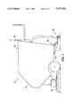
- FIG. 1is a side elevational abbreviated view of a cleaning machine having the squeegee blade assembly of the present invention
- FIG. 2is a perspective view of the squeegee blade assembly showing its connection to the squeegee mounting assembly;
- FIG. 3is an exploded view of the squeegee blade assembly and portions of the squeegee mounting assembly
- FIG. 4is a lateral, cross-sectional view illustrating the interconnection and arrangement among the holding subassembly and the squeegee blades including use of the same mounting connectors to connect the squeegee blade assembly to the squeegee mounting assembly and to connect the squeegee blades to the holding subassembly.
- a floor cleaning machine 10is generally represented, which is useful in cleaning the surface of a floor as the machine 10 moves thereacross.
- the machine 10includes a housing unit 14 comprising a body 18 and a frame 22 with a scrubbing assembly 24 connected to the housing unit 14.
- the housing unit 14contains a number of components (not shown) that are necessary for the operation of the machine 10 and are common to various floor cleaning machines.
- These componentsmay include, among other items, a clean solution tank for containing the liquid used in cleaning the floor surface, a spent solution tank that receives the liquid from the floor surface that remains after the cleaning step and is picked up by the machine 10, a vacuum motor for drawing the spent liquid into the machine, hoses and/or conduits for carrying liquid, and electrical controls involved in the cleaning operation and movement of the cleaning machine 10.
- the cleaning machine 10also has a squeegee mounting assembly 26 that is used to connect a squeegee assembly 30 to the housing unit 14.
- the mounting assembly 26comprises a linking member 34 that is joined to a bracket assembly 38 by means of a tongue 42.
- the bracket assembly 38is connected to the squeegee assembly 30.
- the linking member 34is connected to the housing unit 14 and is used in raising/lowering the squeegee assembly 30.
- portions of a squeegee lifting mechanism 46are illustrated, with this mechanism including a lifting wire 50 and a pulley 54 along which the lifting wire 50 rides.
- the free end of the lifting wire 50is attached to an end terminator 58.
- the opposite end of the lifting wire 50is connected to a control lever or handle 62, which is schematically illustrated in FIG. 1.
- the lifting mechanism 46also includes a spring member 66.
- the handle 62In lifting the squeegee assembly 30 upwardly away from the floor surface, the handle 62 is moved to cause the lifting wire 50 to raise the linking member 34 against the force of the spring member 66.
- the lifting wire 50Conversely, when the handle 62 is a moved in a different direction, the lifting wire 50 is released so that the force of the spring member 66 causes the linking member 34 to move downwardly and thereby move the squeegee assembly 30 against the floor surface.
- the bracket assembly 38includes a bracket body 70 having a flange 74 located at one end of the bracket body 70 and a web 78 located at the opposite end.
- the flange 74is connected to an angle member 82.
- Each of the flange 74 and the angle member 82has an aperture aligned with each other.
- a first mounting connector 86is located through these two apertures for connecting the angle member 82 and the flange 74 to the squeegee assembly 30.
- these partsare also used to achieve a desired position of squeegee blades of the squeegee assembly 30.
- an adjusting washer 90is threadably connected to a shaft 94.
- a pair of stop members 98, 102are spaced from each other a sufficient distance so that the upper end of the first mounting connector 86 is located therebetween.
- a cotter pin 106prevents unwanted outward/upward movement of the angle member 82.
- the securing washer 90is rotatable along the threaded shaft 94 so that the shaft 94, together with the stop members 98,102 affixed thereto, are movable whereby the top end of the first mounting connector 86 can be caused to tilt off vertical to some slight amount or degree.
- the web 78has a guide channel 110 for receiving a second mounting connector 114.
- the head of the second mounting connector 114has a greater width or diameter than that of the guide channel 110.
- the second mounting connector 114is also used in holding the squeegee blades in place.
- the squeegee assembly 30includes a squeegee holding subassembly 122 and a squeegee blade subassembly 126.
- the holding subassembly 122comprises a first contacting shoe 130 and a second contacting shoe 134.
- the squeegee blade subassembly 126comprises a first squeegee blade 138 and a second squeegee blade 142.
- the second contacting shoe 134is disposed inwardly relative to the first contacting shoe 130, with the first and second squeegee blades 138,142 positioned therebetween for use in holding the squeegee blade subassembly 126 to the holding subassembly 122, as seen in FIG. 4.
- the first contacting shoe 130includes an elongated base plate 146 and first and second legs 150, 154.
- Each of the legs 150, 154extends downwardly away from the base plate 146 in a direction substantially normal thereto.
- the combination of the base plate 146 and the first and second legs 150, 154results in a substantially U-shaped cross-section.
- the legs 150, 154are integrally joined to opposite longitudinal extending edges of the base section 146.
- First and second wing pairsare formed at opposite ends of the length or longitudinal extent of the first and second legs 150, 154.
- a first wing member 158is integrally part of the first leg 150 at a first end thereof and a second wing member 162 is integrally part of the second leg 154.
- the wing members 158, 162converge towards each other at their free ends.
- a third wing member 166is integrally part of the first leg 150 and a fourth wing member 170 is integrally part of the second leg 154. The free ends of the wing members 166, 170 also converge toward each other.
- the base section 146also has a number of holes 174. Each of the holes 174 is located at predetermined positions. In the embodiment illustrated, there are six holes 174a-174f provided in the base section 146. The holes 174b, 174e are in alignment with the apertures in the angle member 82 and the guide channel 110, respectively. The holes 174a, 174f at opposite ends of the length of the base section 146 each receives a roller connector 178 to which a roller 180 is joined. The rollers 180a, 180b are used in preventing contact between wall surfaces and the squeegee assembly 30 since the rollers 180a, 180b come in contact with these surfaces first and prevent contact with other parts of the squeegee assembly 30.
- a slotover which a hose connector 182 is positioned.
- the hose connector 182has opened ends, with the end connected to the base section 146 communicating with the slot and the opposite opened end for connection to a hose 184 or the like.
- the hose 184communicates with a vacuum source for drawing up spent liquid that is found on the floor surface over which the cleaning machine 10 moves through the hose connector 182.
- a caster assembly 186is connected to the holding subassembly 122.
- the caster assembly 186includes a plate 188 to which a caster wheel 190 is attached using a caster shaft 192 and nut 194.
- the caster plate 188is connected to the holding subassembly 122 using caster connectors 196a, 196b.
- the caster connectors 196a, 196bare also used in connecting the squeegee blades 138, 142 to the holding subassembly 122.
- the shafts of the connectors 196a, 196bextend through the holes 174c, 174d formed in the base section 146.
- the second contacting shoe 134comprises an elongated center section 200, together with first and second arms 204, 208 that extend along the length of the center section 200.
- the first and second arms 204, 208extend downwardly in a direction substantially normal to the plane of the center section 200.
- This configurationresults in a substantially U-shaped cross-section along the lengths of the integral combination of the first and second legs 204, 208 and center section 200.
- the center section 200has bores 212 formed therethrough and spaced from each other along the length of the center section 200. Each of the bores 212 is aligned with one of the holes 174 in the first contacting shoe 130. There are six bores 212a-212f spaced from each other along the length of the center section 200.
- the connectors 178a, 86, 196a, 196b, 114, 178bare located through the holes 174a-174f, respectively, and also through the bores 212a-212f, respectively.
- a slot 220is also formed through the center section 200 at about the midportion of the length thereof. The slot 220 is aligned with the hose connector 182 and is provided to receive spent liquid during operation of the squeegee assembly 30.
- fasteners 224a-224fin the form of nuts, are joined by welding or the like to the center section 200.
- the fasteners 224a-224fare threaded for receiving the threaded connectors 178a, 86, 196a, 196b, 114, 178b.
- each squeegee blade 138, 142is characterized as having an upper section 230 and a lower section 234.
- Each upper section 230is the part of the squeegee blade 138, 142 that is held between the first and second contacting shoes 130, 134.
- Each of the upper sections 230comprises a first or horizontal member 238 and a second or vertical member 242.
- the horizontal and vertical members 238, 242define an angle therebetween, which is about 90°.
- each squeegee blade 138, 142is integrally formed with the upper sections 230, with the free ends of the lower sections 234 for contacting the floor surface during operation of the squeegee assembly 30.
- the lower sections 234preferably include a number of slits 246 located along the length thereof to provide a passage for the air and liquid mixture, which passage is necessary in order to pick up the liquid on the floor surface.
- the squeegee blades 138,142are dual durometer blades in which the upper sections 230 have a greater hardness than the lower sections 234.
- the hardness of the upper sections 230are greater than about twice the hardness of the lower sections 234.
- the upper sections 230have a durometer value of shore A 90 and the lower sections 234 have a durometer value of shore A 40.
- the harder upper sections 230enhance and contribute to holding the squeegee blades 138, 142 between the first and second contacting shoes 130, 134 while the less hard lower portions 234 enhance and contribute to the desired resiliency of those portions of the squeegee blades 138, 142 that contact the floor surface in connection with the wiping up of spent liquid and removal of thin films of liquid as the cleaning machine 10 moves across the floor surface.
- the upper sections 230are located between the first and second contacting shoes 130, 134. More particularly, the first or horizontal members 238 of the upper sections 230 occupy a space between the inner surface of the base plate and the outer surface of the center section 200. The lengths or extents of the first or horizontal members 238 are sufficient so that they butt up against the outer diameters of the fasteners 224.
- the lengths of the horizontal members 238are less than a length that would overlie the bores 212 and prevent the connectors 86, 114, 178a, 178b, 196a, 196b from being received therethrough.
- the vertical members 242 of the upper sections 230extend between the inner surface of the legs 150, 154 and the outer surfaces of the arms 294, 298.
- the lower sections 234 of the blades 138, 142are not positioned between the legs and the arms, but extend outwardly therefrom.
- the connectors 86, 114, 178a, 178b, 196a, 196bare threadably located through the base plate holes 174 and center section bores 212. This arrangement tightly interconnects the first and second contacting shoes 130, 134 by creating a compressive force in a direction substantially parallel to the length of the connectors 86, 114, 178a, 178b, 196a, 196b.
- a second compressive forceis provided along the second or vertical members 242 of the upper sections 230 due to the interconnection between the first and second contacting shoes 130, 134 together with the tight or close fitting achieved by the dimensions and arrangement among the legs and arms of the contacting shoes, as well as that of the vertical members 242.
- the bracket assembly 38is disconnected from the squeegee assembly 30 by removing the cotter pin 106 from the first mounting connector 86 and then lifting the flange 74 upwardly away from the holding subassembly 122.
- the web 78is then moved in a leftward direction, with reference to FIG. 2, so that the guide channel 110 is moved by and away from the second mounting connector 114. This disconnection results in the squeegee blade assembly 30 being detached from the housing unit 14.
- each of the connectors 86, 114,178a, 178b, 196a, 196bis untightened.
- the user or operator of the cleaning machine 10is then able to separate the first and second contacting shoes 130, 134 from each other and also remove the squeegee blades 138, 142.
- the squeegee blades 138, 142can be replaced with new squeegee blades or interchanged or, perhaps, only one of the two squeegee blades needs to be replaced.
- the upper sections 230 thereofcan be positioned adjacent the inner surfaces of the first contacting shoe 130 and then the second contacting shoe 74 can be located inwardly.
- the holding subassembly 122 and the squeegee blade subassembly 126are then connected together by means of the connectors, with these connectors also connecting the squeegee mounting assembly 26, rollers 178a, 178b and caster assembly 186 to the squeegee assembly 30.
Landscapes
- Screen Printers (AREA)
Abstract
Description
Claims (16)
Priority Applications (1)
| Application Number | Priority Date | Filing Date | Title |
|---|---|---|---|
| US08/060,874US5377382A (en) | 1993-05-13 | 1993-05-13 | Floor cleaning machine including squeegee assembly |
Applications Claiming Priority (1)
| Application Number | Priority Date | Filing Date | Title |
|---|---|---|---|
| US08/060,874US5377382A (en) | 1993-05-13 | 1993-05-13 | Floor cleaning machine including squeegee assembly |
Publications (1)
| Publication Number | Publication Date |
|---|---|
| US5377382Atrue US5377382A (en) | 1995-01-03 |
Family
ID=22032285
Family Applications (1)
| Application Number | Title | Priority Date | Filing Date |
|---|---|---|---|
| US08/060,874Expired - LifetimeUS5377382A (en) | 1993-05-13 | 1993-05-13 | Floor cleaning machine including squeegee assembly |
Country Status (1)
| Country | Link |
|---|---|
| US (1) | US5377382A (en) |
Cited By (50)
| Publication number | Priority date | Publication date | Assignee | Title |
|---|---|---|---|---|
| US5454138A (en)* | 1994-10-17 | 1995-10-03 | Minuteman International, Inc. | Squegee mounting for floor scrubber |
| US5555597A (en)* | 1994-12-29 | 1996-09-17 | Shop Vac Corporation | Apparatus for converting a vacuum cleaning device into a liquid dispensing and suctioning system |
| US5579555A (en)* | 1995-10-10 | 1996-12-03 | The National Super Service Company | Squeegee assembly for floor cleaning machine |
| US5600866A (en)* | 1995-12-12 | 1997-02-11 | Shop Vac Corporation | Cleaning fluid tank assembly |
| US5611108A (en)* | 1994-04-25 | 1997-03-18 | Windsor Industries, Inc. | Floor cleaning apparatus with slidable flap |
| FR2740023A1 (en)* | 1995-10-23 | 1997-04-25 | Gansow Maschbau Gmbh Co Kg | SUCTION FOOT FOR A SOIL CLEANER ON WHEELS |
| EP0800783A3 (en)* | 1996-03-01 | 1997-10-22 | Unilever Nv | |
| US5809605A (en)* | 1997-04-15 | 1998-09-22 | Allway Tools, Inc. | Squeegee assembly |
| US5881417A (en)* | 1994-04-25 | 1999-03-16 | Windsor Industries, Inc. | Floor cleaning apparatus with contouring broom |
| US5911260A (en)* | 1996-05-17 | 1999-06-15 | Amano Corporation | Squeegee assembly for floor surface cleaning machine |
| US5918346A (en)* | 1996-05-17 | 1999-07-06 | Amano Corporation | Squeegee assembly for floor surface cleaning machine |
| US6108859A (en)* | 1998-07-29 | 2000-08-29 | Alto U. S. Inc. | High efficiency squeegee |
| EP1197606A1 (en)* | 2000-10-13 | 2002-04-17 | Mathieu Yno | Apparatus for the suction of waste water from areas covered with paving elements or concrete |
| FR2815363A1 (en)* | 2000-10-13 | 2002-04-19 | Mathieu Yno S A | Cleaning-brushing vehicle residual rinsing water suction unit comprises two horizontal scraper arms in front of suction nozzle intake |
| US6397429B1 (en) | 2000-06-30 | 2002-06-04 | Nilfisk-Advance, Inc. | Riding floor scrubber |
| US6442789B1 (en) | 1999-06-30 | 2002-09-03 | Nilfisk-Advance, Inc. | Riding floor scrubber |
| US6591448B1 (en) | 2000-11-20 | 2003-07-15 | Alto Us Inc. | Carpet extraction machine recovery tool |
| US6602018B2 (en) | 2000-04-17 | 2003-08-05 | Tennant Company | Squeegee assembly having a non-destructive release mode |
| US6647585B1 (en)* | 2000-11-06 | 2003-11-18 | Kaivac, Inc. | Multi-functional floor-cleaning tool |
| US20030233729A1 (en)* | 2002-06-20 | 2003-12-25 | Tucker Alan Wayne | Squeegee with clog reduction structure |
| US20040025288A1 (en)* | 2002-03-21 | 2004-02-12 | Hamline Anthony John | Tool mounting assembly for a surface maintenance machine |
| WO2005107561A3 (en)* | 2004-04-23 | 2006-06-15 | Minuteman International Inc | Quick-change squeegee for floor scrubber |
| DE102007034702A1 (en)* | 2007-07-18 | 2009-01-22 | Alfred Kärcher Gmbh & Co. Kg | Dirt picking device for a floor cleaning machine and floor cleaning machine with such a dirt collecting device |
| KR100881940B1 (en)* | 2007-10-19 | 2009-02-04 | 한경희 | Vacuum cleaner suction hose |
| US20090113666A1 (en)* | 2006-02-07 | 2009-05-07 | Johnson Kale R | Squeegee Assembly |
| WO2009127836A1 (en)* | 2008-04-18 | 2009-10-22 | Numatic International Limited | Floor treatment machine |
| US20090300868A1 (en)* | 2005-12-22 | 2009-12-10 | Johnsondiversey, Inc. | Squeegee assembly for a floor cleaning machine |
| USD613472S1 (en) | 2006-02-01 | 2010-04-06 | Johnsondiversey, Inc. | Combined squeegee and support frame |
| US20110107552A1 (en)* | 2009-11-09 | 2011-05-12 | Tennant Company | Squeegee Assembly |
| USD654234S1 (en) | 2010-12-08 | 2012-02-14 | Karcher North America, Inc. | Vacuum bag |
| EP2484262A1 (en)* | 2011-02-03 | 2012-08-08 | HEFTER Maschinenbau GmbH & Co. KG | Suction strip for draining subsoil |
| USD669646S1 (en) | 2011-05-05 | 2012-10-23 | Emerson Electric Co. | Combined wet/dry vacuum cleaner |
| USD670046S1 (en) | 2011-01-21 | 2012-10-30 | Emerson Electric Co. | Combined wet/dry vacuum cleaner |
| USD676205S1 (en) | 2011-04-12 | 2013-02-12 | Emerson Electric Co. | Combined wet/dry vacuum cleaner |
| US20140130295A1 (en)* | 2012-11-13 | 2014-05-15 | Robert S. Robinson | Wide-area vacuum/squeegee head floor cleaning tool |
| US8756756B2 (en) | 2011-10-03 | 2014-06-24 | Emerson Electric Co. | Vacuum appliance with adjustable tool support system and method of use |
| US8887340B2 (en) | 2003-05-14 | 2014-11-18 | Kärcher North America, Inc. | Floor cleaning apparatus |
| US8966693B2 (en) | 2009-08-05 | 2015-03-03 | Karcher N. America, Inc. | Method and apparatus for extended use of cleaning fluid in a floor cleaning machine |
| US9015887B1 (en) | 2003-05-14 | 2015-04-28 | Kärcher North America, Inc. | Floor treatment apparatus |
| US20150121647A1 (en)* | 2012-08-07 | 2015-05-07 | Karcher North America, Inc. | Floor cleaning tool having a mechanically operated pump |
| WO2016000745A1 (en)* | 2014-06-30 | 2016-01-07 | Alfred Kärcher Gmbh & Co. Kg | Dirt receptacle and floor cleaning device comprising a dirt receptacle |
| US20170002530A1 (en)* | 2015-07-01 | 2017-01-05 | Kann Manufacturing Corporation | Garbage truck sweeper attachment |
| EP3135176A1 (en) | 2015-08-26 | 2017-03-01 | Midwest Rubber Service & Supply Company | Squeegee with seal flap |
| EP3178363A1 (en) | 2015-12-08 | 2017-06-14 | Wetrok AG | Suction beam for a floor cleaning machine |
| US20180110385A1 (en)* | 2016-10-25 | 2018-04-26 | Shop Vac Corporation | Vacuum squeegee accessory |
| US20190053684A1 (en)* | 2017-08-16 | 2019-02-21 | Simon Ralph Cassar | Reversable blade squeegee with winglet tips |
| US10786131B2 (en) | 2011-07-31 | 2020-09-29 | Kaivac, Inc. | Multi-functional cleaning and floor care system |
| USD907868S1 (en) | 2019-01-24 | 2021-01-12 | Karcher North America, Inc. | Floor cleaner |
| US11517171B2 (en)* | 2019-07-26 | 2022-12-06 | Lilly Brush Co., LLC | Detailing tool |
| US12070181B2 (en) | 2017-05-04 | 2024-08-27 | Alfred Kärcher SE & Co. KG | Floor cleaning appliance and method for cleaning a floor surface |
Citations (17)
| Publication number | Priority date | Publication date | Assignee | Title |
|---|---|---|---|---|
| US2876484A (en)* | 1953-10-19 | 1959-03-10 | Arthur L Wells | Apparatus for processing surfaces |
| US3028692A (en)* | 1960-03-24 | 1962-04-10 | Brock George | Snow ploughs and like surface scraping appliances |
| US3065490A (en)* | 1960-08-02 | 1962-11-27 | Advance Floor Machine Company | Shiftable pick-up squeegee unit for floor treating machine |
| US3376597A (en)* | 1966-02-02 | 1968-04-09 | Boyd Clarence | Floor scrubbing machine |
| US3496591A (en)* | 1967-07-20 | 1970-02-24 | Kel Tec Inc | Floor maintenance machine |
| US3550181A (en)* | 1968-01-24 | 1970-12-29 | Scott & Fetzer Co | Apparatus for cleaning floors |
| US4041567A (en)* | 1975-04-10 | 1977-08-16 | The Scott & Fetzer Company | Combination sweeping-scrubbing apparatus |
| US4075730A (en)* | 1976-09-20 | 1978-02-28 | Greenview Manufacturing Company | Non-metallic squeegee for showerbath surfaces and the like |
| US4173056A (en)* | 1978-06-26 | 1979-11-06 | Tennant Company | Scrubbing machine with tracking squeegee |
| US4293971A (en)* | 1979-06-19 | 1981-10-13 | Clarke-Gravely Corporation | Floor treating machine with squeegee |
| US4363152A (en)* | 1981-02-19 | 1982-12-14 | The Scott & Fetzer Company | Squeegee assembly for a scrubbing machine |
| US4429433A (en)* | 1982-08-27 | 1984-02-07 | The Scott & Fetzer Company | Surface cleaning machine with squeegee assembly |
| US4492002A (en)* | 1980-09-12 | 1985-01-08 | Wetrok, Inc. | Floor cleaning machine |
| US4765015A (en)* | 1987-01-28 | 1988-08-23 | Idroplina S.R.L. | Floor sweeping blade device for surface cleaning machines |
| US4809396A (en)* | 1987-06-29 | 1989-03-07 | Houser Franklin C | Combination vacuum and solution-dispensing apparatus |
| US4937911A (en)* | 1988-06-03 | 1990-07-03 | Picchietti Sr Remo | Bowling alley lane cleaning apparatus |
| US5239720A (en)* | 1991-10-24 | 1993-08-31 | Advance Machine Company | Mobile surface cleaning machine |
- 1993
- 1993-05-13USUS08/060,874patent/US5377382A/ennot_activeExpired - Lifetime
Patent Citations (17)
| Publication number | Priority date | Publication date | Assignee | Title |
|---|---|---|---|---|
| US2876484A (en)* | 1953-10-19 | 1959-03-10 | Arthur L Wells | Apparatus for processing surfaces |
| US3028692A (en)* | 1960-03-24 | 1962-04-10 | Brock George | Snow ploughs and like surface scraping appliances |
| US3065490A (en)* | 1960-08-02 | 1962-11-27 | Advance Floor Machine Company | Shiftable pick-up squeegee unit for floor treating machine |
| US3376597A (en)* | 1966-02-02 | 1968-04-09 | Boyd Clarence | Floor scrubbing machine |
| US3496591A (en)* | 1967-07-20 | 1970-02-24 | Kel Tec Inc | Floor maintenance machine |
| US3550181A (en)* | 1968-01-24 | 1970-12-29 | Scott & Fetzer Co | Apparatus for cleaning floors |
| US4041567A (en)* | 1975-04-10 | 1977-08-16 | The Scott & Fetzer Company | Combination sweeping-scrubbing apparatus |
| US4075730A (en)* | 1976-09-20 | 1978-02-28 | Greenview Manufacturing Company | Non-metallic squeegee for showerbath surfaces and the like |
| US4173056A (en)* | 1978-06-26 | 1979-11-06 | Tennant Company | Scrubbing machine with tracking squeegee |
| US4293971A (en)* | 1979-06-19 | 1981-10-13 | Clarke-Gravely Corporation | Floor treating machine with squeegee |
| US4492002A (en)* | 1980-09-12 | 1985-01-08 | Wetrok, Inc. | Floor cleaning machine |
| US4363152A (en)* | 1981-02-19 | 1982-12-14 | The Scott & Fetzer Company | Squeegee assembly for a scrubbing machine |
| US4429433A (en)* | 1982-08-27 | 1984-02-07 | The Scott & Fetzer Company | Surface cleaning machine with squeegee assembly |
| US4765015A (en)* | 1987-01-28 | 1988-08-23 | Idroplina S.R.L. | Floor sweeping blade device for surface cleaning machines |
| US4809396A (en)* | 1987-06-29 | 1989-03-07 | Houser Franklin C | Combination vacuum and solution-dispensing apparatus |
| US4937911A (en)* | 1988-06-03 | 1990-07-03 | Picchietti Sr Remo | Bowling alley lane cleaning apparatus |
| US5239720A (en)* | 1991-10-24 | 1993-08-31 | Advance Machine Company | Mobile surface cleaning machine |
Cited By (78)
| Publication number | Priority date | Publication date | Assignee | Title |
|---|---|---|---|---|
| US5611108A (en)* | 1994-04-25 | 1997-03-18 | Windsor Industries, Inc. | Floor cleaning apparatus with slidable flap |
| US5628086A (en)* | 1994-04-25 | 1997-05-13 | Windsor Industries, Inc. | Floor cleaning apparatus with squeegee mounting system |
| US5630246A (en)* | 1994-04-25 | 1997-05-20 | Windsor Industries, Inc. | Floor cleaning apparatus with flap having wear indicator |
| US5881417A (en)* | 1994-04-25 | 1999-03-16 | Windsor Industries, Inc. | Floor cleaning apparatus with contouring broom |
| US5454138A (en)* | 1994-10-17 | 1995-10-03 | Minuteman International, Inc. | Squegee mounting for floor scrubber |
| US5555597A (en)* | 1994-12-29 | 1996-09-17 | Shop Vac Corporation | Apparatus for converting a vacuum cleaning device into a liquid dispensing and suctioning system |
| US5579555A (en)* | 1995-10-10 | 1996-12-03 | The National Super Service Company | Squeegee assembly for floor cleaning machine |
| FR2740023A1 (en)* | 1995-10-23 | 1997-04-25 | Gansow Maschbau Gmbh Co Kg | SUCTION FOOT FOR A SOIL CLEANER ON WHEELS |
| US5600866A (en)* | 1995-12-12 | 1997-02-11 | Shop Vac Corporation | Cleaning fluid tank assembly |
| EP0800783A3 (en)* | 1996-03-01 | 1997-10-22 | Unilever Nv | |
| US5933911A (en)* | 1996-03-01 | 1999-08-10 | Diversey Lever, Inc. | Apparatus for cleaning a ground |
| US5918346A (en)* | 1996-05-17 | 1999-07-06 | Amano Corporation | Squeegee assembly for floor surface cleaning machine |
| US5911260A (en)* | 1996-05-17 | 1999-06-15 | Amano Corporation | Squeegee assembly for floor surface cleaning machine |
| US5809605A (en)* | 1997-04-15 | 1998-09-22 | Allway Tools, Inc. | Squeegee assembly |
| US6108859A (en)* | 1998-07-29 | 2000-08-29 | Alto U. S. Inc. | High efficiency squeegee |
| US6442789B1 (en) | 1999-06-30 | 2002-09-03 | Nilfisk-Advance, Inc. | Riding floor scrubber |
| US6602018B2 (en) | 2000-04-17 | 2003-08-05 | Tennant Company | Squeegee assembly having a non-destructive release mode |
| US6397429B1 (en) | 2000-06-30 | 2002-06-04 | Nilfisk-Advance, Inc. | Riding floor scrubber |
| US6519808B2 (en)* | 2000-06-30 | 2003-02-18 | Nilfisk-Advance, Inc. | Squeegee mounting assembly for a floor scrubber |
| FR2815363A1 (en)* | 2000-10-13 | 2002-04-19 | Mathieu Yno S A | Cleaning-brushing vehicle residual rinsing water suction unit comprises two horizontal scraper arms in front of suction nozzle intake |
| EP1197606A1 (en)* | 2000-10-13 | 2002-04-17 | Mathieu Yno | Apparatus for the suction of waste water from areas covered with paving elements or concrete |
| US6647585B1 (en)* | 2000-11-06 | 2003-11-18 | Kaivac, Inc. | Multi-functional floor-cleaning tool |
| US6591448B1 (en) | 2000-11-20 | 2003-07-15 | Alto Us Inc. | Carpet extraction machine recovery tool |
| US20040025288A1 (en)* | 2002-03-21 | 2004-02-12 | Hamline Anthony John | Tool mounting assembly for a surface maintenance machine |
| US7059015B2 (en)* | 2002-03-21 | 2006-06-13 | Tennant Company | Tool mounting assembly for a surface maintenance machine |
| US20030233729A1 (en)* | 2002-06-20 | 2003-12-25 | Tucker Alan Wayne | Squeegee with clog reduction structure |
| US6895633B2 (en) | 2002-06-20 | 2005-05-24 | Tennant Company | Squeegee with clog reduction structure |
| US9451861B2 (en) | 2003-05-14 | 2016-09-27 | Kärcher North America, Inc. | Floor treatment apparatus |
| US8887340B2 (en) | 2003-05-14 | 2014-11-18 | Kärcher North America, Inc. | Floor cleaning apparatus |
| US10555657B2 (en) | 2003-05-14 | 2020-02-11 | Kärcher North America, Inc. | Floor treatment apparatus |
| US9757005B2 (en) | 2003-05-14 | 2017-09-12 | Kärcher North America, Inc. | Floor treatment apparatus |
| US9730566B2 (en) | 2003-05-14 | 2017-08-15 | Kärcher North America, Inc. | Floor treatment apparatus |
| US9510721B2 (en) | 2003-05-14 | 2016-12-06 | Karcher North America, Inc. | Floor cleaning apparatus |
| US9192276B2 (en) | 2003-05-14 | 2015-11-24 | Karcher North America, Inc. | Floor cleaning apparatus |
| US9015887B1 (en) | 2003-05-14 | 2015-04-28 | Kärcher North America, Inc. | Floor treatment apparatus |
| WO2005107561A3 (en)* | 2004-04-23 | 2006-06-15 | Minuteman International Inc | Quick-change squeegee for floor scrubber |
| US8918954B2 (en) | 2005-12-22 | 2014-12-30 | Diversey, Inc. | Squeegee assembly for a floor cleaning machine |
| US20110214692A1 (en)* | 2005-12-22 | 2011-09-08 | Diversey, Inc. | Squeegee assembly for a floor cleaning machine |
| US20090300868A1 (en)* | 2005-12-22 | 2009-12-10 | Johnsondiversey, Inc. | Squeegee assembly for a floor cleaning machine |
| US8261408B2 (en) | 2005-12-22 | 2012-09-11 | Diversey, Inc. | Squeegee assembly for a floor cleaning machine |
| US20110197916A1 (en)* | 2005-12-22 | 2011-08-18 | Diversey, Inc. | Squeegee assembly for a floor cleaning machine |
| US7950106B2 (en) | 2005-12-22 | 2011-05-31 | Diversey, Inc. | Squeegee assembly for a floor cleaning machine |
| US8875338B2 (en)* | 2005-12-22 | 2014-11-04 | Diversey, Inc. | Squeegee assembly for a floor cleaning machine |
| USD613472S1 (en) | 2006-02-01 | 2010-04-06 | Johnsondiversey, Inc. | Combined squeegee and support frame |
| US20090113666A1 (en)* | 2006-02-07 | 2009-05-07 | Johnson Kale R | Squeegee Assembly |
| US8166606B2 (en)* | 2006-02-07 | 2012-05-01 | Nilfisk-Advance, Inc. | Squeegee assembly |
| DE102007034702A1 (en)* | 2007-07-18 | 2009-01-22 | Alfred Kärcher Gmbh & Co. Kg | Dirt picking device for a floor cleaning machine and floor cleaning machine with such a dirt collecting device |
| US20100180397A1 (en)* | 2007-07-18 | 2010-07-22 | Alfred Kaercher Gmbh & Co. Kg | Dirt-collecting device for a floor-cleaning machine, and floor-cleaning machine having such a dirt-collecting device |
| US8302254B2 (en)* | 2007-07-18 | 2012-11-06 | Alfred Kaercher Gmbh & Co. Kg | Dirt-collecting device for a floor-cleaning machine, and floor-cleaning machine having such a dirt-collecting device |
| KR100881940B1 (en)* | 2007-10-19 | 2009-02-04 | 한경희 | Vacuum cleaner suction hose |
| WO2009127836A1 (en)* | 2008-04-18 | 2009-10-22 | Numatic International Limited | Floor treatment machine |
| US8966693B2 (en) | 2009-08-05 | 2015-03-03 | Karcher N. America, Inc. | Method and apparatus for extended use of cleaning fluid in a floor cleaning machine |
| US20110107552A1 (en)* | 2009-11-09 | 2011-05-12 | Tennant Company | Squeegee Assembly |
| US8595896B2 (en)* | 2009-11-09 | 2013-12-03 | Tennant Company | Squeegee assembly |
| USD654234S1 (en) | 2010-12-08 | 2012-02-14 | Karcher North America, Inc. | Vacuum bag |
| USD670046S1 (en) | 2011-01-21 | 2012-10-30 | Emerson Electric Co. | Combined wet/dry vacuum cleaner |
| EP2484262A1 (en)* | 2011-02-03 | 2012-08-08 | HEFTER Maschinenbau GmbH & Co. KG | Suction strip for draining subsoil |
| USD676205S1 (en) | 2011-04-12 | 2013-02-12 | Emerson Electric Co. | Combined wet/dry vacuum cleaner |
| USD669646S1 (en) | 2011-05-05 | 2012-10-23 | Emerson Electric Co. | Combined wet/dry vacuum cleaner |
| US10786131B2 (en) | 2011-07-31 | 2020-09-29 | Kaivac, Inc. | Multi-functional cleaning and floor care system |
| US8756756B2 (en) | 2011-10-03 | 2014-06-24 | Emerson Electric Co. | Vacuum appliance with adjustable tool support system and method of use |
| US20150121647A1 (en)* | 2012-08-07 | 2015-05-07 | Karcher North America, Inc. | Floor cleaning tool having a mechanically operated pump |
| US9877624B2 (en)* | 2012-08-07 | 2018-01-30 | Kärcher North America, Inc. | Floor cleaning tool having a mechanically operated pump |
| US20140130295A1 (en)* | 2012-11-13 | 2014-05-15 | Robert S. Robinson | Wide-area vacuum/squeegee head floor cleaning tool |
| WO2016000745A1 (en)* | 2014-06-30 | 2016-01-07 | Alfred Kärcher Gmbh & Co. Kg | Dirt receptacle and floor cleaning device comprising a dirt receptacle |
| RU2645615C1 (en)* | 2014-06-30 | 2018-02-26 | Альфред Кэрхер Гмбх Унд Ко. Кг | Dirt collecting device and floor cleaner with such dirt collecting device |
| US9907448B2 (en) | 2014-06-30 | 2018-03-06 | Alfred Kärcher GmbH & Co., KG | Dirt pick-up device and floor cleaner with a dirt pick-up device |
| US20170002530A1 (en)* | 2015-07-01 | 2017-01-05 | Kann Manufacturing Corporation | Garbage truck sweeper attachment |
| US10815629B2 (en)* | 2015-07-01 | 2020-10-27 | Kann Manufacturing Corporation | Garbage truck sweeper attachment |
| EP3135176A1 (en) | 2015-08-26 | 2017-03-01 | Midwest Rubber Service & Supply Company | Squeegee with seal flap |
| US10376121B2 (en) | 2015-08-26 | 2019-08-13 | Midwest Rubber Service & Supply Company | Squeegee with seal flap |
| EP3178363A1 (en) | 2015-12-08 | 2017-06-14 | Wetrok AG | Suction beam for a floor cleaning machine |
| US10631695B2 (en)* | 2016-10-25 | 2020-04-28 | Shop Vac Corporation | Vacuum squeegee accessory |
| US20180110385A1 (en)* | 2016-10-25 | 2018-04-26 | Shop Vac Corporation | Vacuum squeegee accessory |
| US12070181B2 (en) | 2017-05-04 | 2024-08-27 | Alfred Kärcher SE & Co. KG | Floor cleaning appliance and method for cleaning a floor surface |
| US20190053684A1 (en)* | 2017-08-16 | 2019-02-21 | Simon Ralph Cassar | Reversable blade squeegee with winglet tips |
| USD907868S1 (en) | 2019-01-24 | 2021-01-12 | Karcher North America, Inc. | Floor cleaner |
| US11517171B2 (en)* | 2019-07-26 | 2022-12-06 | Lilly Brush Co., LLC | Detailing tool |
Similar Documents
| Publication | Publication Date | Title |
|---|---|---|
| US5377382A (en) | Floor cleaning machine including squeegee assembly | |
| US8875338B2 (en) | Squeegee assembly for a floor cleaning machine | |
| US4429433A (en) | Surface cleaning machine with squeegee assembly | |
| US4293971A (en) | Floor treating machine with squeegee | |
| CN106793901A (en) | surface cleaner | |
| US5579555A (en) | Squeegee assembly for floor cleaning machine | |
| US3649995A (en) | Floor maintenance machine | |
| US8091171B2 (en) | Device and method for coupling a cleaning implement to a floor cleaning machine | |
| JPH1099245A (en) | Squeegee connecting device for floor washer | |
| CN207254796U (en) | Metal surface cleaning device | |
| GB2606241A (en) | Surface treatment head | |
| AU2011202957B2 (en) | Squeegee assembly for a floor cleaning machine | |
| EP0481221A1 (en) | Wiper-scraper | |
| JPS5828554Y2 (en) | Root vegetable washing device | |
| DE20020866U1 (en) | Vacuum cleaner adapter |
Legal Events
| Date | Code | Title | Description |
|---|---|---|---|
| AS | Assignment | Owner name:WINDSOR INDUSTRIES, INC., COLORADO Free format text:ASSIGNMENT OF ASSIGNORS INTEREST;ASSIGNORS:BORES, FREDERICK M.;PLAVEN, THOMAS G.;REEL/FRAME:006557/0485 Effective date:19930512 | |
| STPP | Information on status: patent application and granting procedure in general | Free format text:APPLICATION UNDERGOING PREEXAM PROCESSING | |
| FPAY | Fee payment | Year of fee payment:4 | |
| FPAY | Fee payment | Year of fee payment:8 | |
| AS | Assignment | Owner name:FLEET NATIONAL BANK, MASSACHUSETTS Free format text:SECURITY INTEREST;ASSIGNOR:WINDSOR INDUSTRIES, INC.;REEL/FRAME:014523/0138 Effective date:19980805 | |
| AS | Assignment | Owner name:CASTLE ROCK INDUSTRIES, INC., COLORADO Free format text:ASSIGNMENT OF ASSIGNORS INTEREST;ASSIGNOR:WINDSOR INDUSTRIES, INC.;REEL/FRAME:015251/0775 Effective date:20040407 | |
| AS | Assignment | Owner name:HARRIS TRUST AND SAVINGS BANK, AS ADMINSTRATIVE AG Free format text:SECURITY INTEREST;ASSIGNOR:WINDSOR INDUSTRIES, INCORPORATED;REEL/FRAME:015460/0824 Effective date:20040602 | |
| FPAY | Fee payment | Year of fee payment:12 | |
| AS | Assignment | Owner name:KARCHER FLOOR CARE, INC., COLORADO Free format text:CHANGE OF NAME;ASSIGNOR:CASTLE ROCK INDUSTRIES, INC.;REEL/FRAME:019795/0132 Effective date:20070419 | |
| AS | Assignment | Owner name:KARCHER NORTH AMERICA, INC., COLORADO Free format text:MERGER;ASSIGNORS:KARCHER FLOOR CARE, INC.;KARCHER RESIDENTIAL SOLUTIONS, INC.;REEL/FRAME:022390/0283 Effective date:20081231 |