US5376960A - Video endoscope with solid-state imaging device - Google Patents
Video endoscope with solid-state imaging deviceDownload PDFInfo
- Publication number
- US5376960A US5376960AUS07/943,347US94334792AUS5376960AUS 5376960 AUS5376960 AUS 5376960AUS 94334792 AUS94334792 AUS 94334792AUS 5376960 AUS5376960 AUS 5376960A
- Authority
- US
- United States
- Prior art keywords
- objective lens
- electronic components
- endoscope
- video endoscope
- ceramic substrate
- Prior art date
- Legal status (The legal status is an assumption and is not a legal conclusion. Google has not performed a legal analysis and makes no representation as to the accuracy of the status listed.)
- Expired - Fee Related
Links
Images


Classifications
- A—HUMAN NECESSITIES
- A61—MEDICAL OR VETERINARY SCIENCE; HYGIENE
- A61B—DIAGNOSIS; SURGERY; IDENTIFICATION
- A61B1/00—Instruments for performing medical examinations of the interior of cavities or tubes of the body by visual or photographical inspection, e.g. endoscopes; Illuminating arrangements therefor
- A61B1/04—Instruments for performing medical examinations of the interior of cavities or tubes of the body by visual or photographical inspection, e.g. endoscopes; Illuminating arrangements therefor combined with photographic or television appliances
- A61B1/05—Instruments for performing medical examinations of the interior of cavities or tubes of the body by visual or photographical inspection, e.g. endoscopes; Illuminating arrangements therefor combined with photographic or television appliances characterised by the image sensor, e.g. camera, being in the distal end portion
- A61B1/051—Details of CCD assembly
- A—HUMAN NECESSITIES
- A61—MEDICAL OR VETERINARY SCIENCE; HYGIENE
- A61B—DIAGNOSIS; SURGERY; IDENTIFICATION
- A61B1/00—Instruments for performing medical examinations of the interior of cavities or tubes of the body by visual or photographical inspection, e.g. endoscopes; Illuminating arrangements therefor
- A61B1/04—Instruments for performing medical examinations of the interior of cavities or tubes of the body by visual or photographical inspection, e.g. endoscopes; Illuminating arrangements therefor combined with photographic or television appliances
- A61B1/05—Instruments for performing medical examinations of the interior of cavities or tubes of the body by visual or photographical inspection, e.g. endoscopes; Illuminating arrangements therefor combined with photographic or television appliances characterised by the image sensor, e.g. camera, being in the distal end portion
- H—ELECTRICITY
- H04—ELECTRIC COMMUNICATION TECHNIQUE
- H04N—PICTORIAL COMMUNICATION, e.g. TELEVISION
- H04N23/00—Cameras or camera modules comprising electronic image sensors; Control thereof
- H04N23/50—Constructional details
- H04N23/54—Mounting of pick-up tubes, electronic image sensors, deviation or focusing coils
- H—ELECTRICITY
- H04—ELECTRIC COMMUNICATION TECHNIQUE
- H04N—PICTORIAL COMMUNICATION, e.g. TELEVISION
- H04N23/00—Cameras or camera modules comprising electronic image sensors; Control thereof
- H04N23/50—Constructional details
- H04N23/555—Constructional details for picking-up images in sites, inaccessible due to their dimensions or hazardous conditions, e.g. endoscopes or borescopes
Definitions
- the inventionrelates to a video endoscope, in the distal end region of which an objective lens, a semi-conductor imager assigned to it and further electronic components are arranged.
- Video endoscopes of this typeare suitable for investigating body cavities and for carrying out any operations there at the same time.
- a video endoscopecan also be seen from U.S. Pat. No. 4,809,680 which combines the above-mentioned components in the endoscope tip, but wherein it is designed as a pre-assembled insert, into which the optical system and the electronic components arranged on it can be inserted and which can be attached to the end of a flexible endoscope shaft.
- the objective lens, the semi-conductor imager and further electronic componentsare arranged on an integral ceramic substrate, to which the conductors for joining and for connecting the electronic components and the semi-conductor imager are directly attached, and which sits within the endoscope shaft and is supported by it.
- the advantages which can be achieved using this designconsist particularly in that, in addition to using the advantages of the ceramic materials known per se--reference may be made, for example to the favourable temperature properties--direct application of the electronic components, primarily of the CCD chip, makes it possible to save on the mostly ceramic substrate platelets for the individual components.
- the otherwise conventional basesmay be dispensed with, and additional space is gained because of the lack of the connecting lugs of the electronic components which claim a relatively large amount of space, so that the diameter of the video endoscope may be reduced or more space is available for accommodating the other components, optical system, light guides, instrument channels, intake channels and rinsing channels, electronics and electrical connections.
- the ceramic substratemay have an essentially cuboid support part, the width of which is smaller than the internal diameter of the endoscope shaft and to which a disc-shaped centering part is connected on the end-face side, which extends essentially vertically to the longitudinal extension of the support part and its external contour is adapted to the internal contour of the endoscope shaft.
- a ceramic substrate designed in this manneroffers relatively large surfaces for the arrangement of said parts with a very low space requirement. It is thus advantageous if the centering part is provided with bores, for example for receiving light guides, for introducing an auxiliary instrument, for supplying rinsing liquid and for attaching electrical connections, since this makes complete and exact pre-assembly of the video endoscope head possible without further aligning and mounting aids.
- the objective lensmounted on a ceramic platelet which can be attached to the support part and has bores provided for receiving light guides, which bores are arranged to be aligned with those in the centering part.
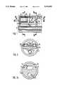
- FIG. 1shows a longitudinal section through a video endoscope head according to the invention
- FIG. 2shows a section along the section line II--II in FIG. 1,
- FIG. 2ashows a section along the section line IIa--IIa in FIG. 1,
- FIG. 3shows a section along the line III--III in FIG. 1,
- FIG. 4shows an alternative embodiment to that represented according to FIG. 3 with a plug board for the connection of signal lines and electronics
- FIG. 5shows a modified design of the video endoscope head in longitudinal section
- FIG. 6shows a longitudinal section through the representation according to FIG. 5 along the section line VI--VI
- FIG. 7shows a further variant of a video endoscope head in longitudinal section
- FIG. 8shows a section along the section line VIII--VIII in FIG. 7.
- FIGS. 1, 2, 2a and 3show the distal endoscope head of a video endoscope.
- this headcomprises a substrate 1 which is made from a ceramic material.
- the ceramic substrate 1has the shape of a T.
- a part extending in the direction of the endoscope axisis designed as support part 1a and has the shape of a cuboid.
- a centering part 1bwhich is adapted to the internal contour of the cylindrical endoscope shaft 2, is connected to the support part 1a at right angles.
- the centering part 1bis provided with bores 3 and 4 as well as a opening 5, as can be seen in FIG. 2a.
- An auxiliary instrument channel 6is passed through the bore 4.
- the bores 3serve to introduce the light guides through the centering part 1b.
- the opening 5is required for attaching electrical connections.
- a platelet 7preferably made from the same ceramic material as the substrate 1 and a solid-state imaging chip (CCD) 8 are arranged on the top side of the support part 1a.
- the platelet 7serves as support part for some of the optical elements which are surrounded by a metal cylinder 10 and form the endoscope objective lens 9.
- the metal cylinder 10is attached in a recess 11 in the platelet 7.
- the platelet 7also has bores 3a which are aligned with the bores 3 in the centering part 1b and serve to introduce the light guides.
- a prism 12is arranged above the solid-state imaging chip 8 and serves to divert the image taken up by the objective lens 9 onto the solid-state imaging chip 8 arranged with its image surface 8a in a plane parallel to the longitudinal axis of the endoscope in this example.
- the end of the endoscopeis finally sealed in conventional manner with a light-permeable cover platelet 13 in the region of the objective lens 9.
- the electrical connection of the attached electronic components 8 or 15 to one anotheris carried out in known manner, for example by bonding or by vapour-deposited strip conductors or similar measures.
- the connection between the electronics situated on the support part 1a and the signal lines 14 leading in the proximal directionis made by means of a tag block 16 according to FIG. 3, while this task is taken over by a plug board 17 in the embodiment according to FIG. 4.
- a likewise essentially T-shaped substrate 1is used, on which the endoscope objective lens 9 and the electronic components 15 are arranged for wiring the solid-state imaging chip 8.
- the solid-state imaging chip 8is arranged vertically to the optical axis of the objective lens 9 with its imaging surface 8a pointing in the direction of the objective lens.
- the ceramic substrate 1is therefore also modified here to the effect that the opening for contact between electronics and signal lines 14 is arranged not as in FIG. 2a, but as lateral opening 5a, as can be seen in FIG. 6.
- the bores 3 for the light guidesare of course also attached in a modified manner, but this is not shown.
- the electronic componentsare also attached directly to the ceramic support 1 in the manner already outlined and, as also described above, connected to one another electrically.
- the connection between electronics and signal linestakes place in the lateral opening 5a, in particular again either by means of a tag block or plug board.
- a ceramic substrate 1 of essentially T-shaped designis again used, but wherein the centering part 1a aligned vertically to the endoscope axis forms the distal end of the endoscope and the cuboid support part 1b points proximally in the direction of the endoscope axis.
- the arrangement of the endoscope objective lens 9 and the electronic components 8 or 15takes place here in the manner previously described for the embodiment according to FIGS. 1 to 4. As can be seen from FIG.
- two rinsing channels 18, by means of which the light-permeable cover platelet 13 in front of the distal end of the objective lens 9 can be rinsed free of impurities,are provided in addition to the channels already mentioned, so that an optimum image can always be achieved.
Landscapes
- Health & Medical Sciences (AREA)
- Life Sciences & Earth Sciences (AREA)
- Surgery (AREA)
- Engineering & Computer Science (AREA)
- Radiology & Medical Imaging (AREA)
- Heart & Thoracic Surgery (AREA)
- Biophysics (AREA)
- Nuclear Medicine, Radiotherapy & Molecular Imaging (AREA)
- Optics & Photonics (AREA)
- Pathology (AREA)
- Veterinary Medicine (AREA)
- Public Health (AREA)
- Biomedical Technology (AREA)
- Physics & Mathematics (AREA)
- Medical Informatics (AREA)
- Molecular Biology (AREA)
- Animal Behavior & Ethology (AREA)
- General Health & Medical Sciences (AREA)
- Multimedia (AREA)
- Signal Processing (AREA)
- Endoscopes (AREA)
- Instruments For Viewing The Inside Of Hollow Bodies (AREA)
Abstract
Description
Claims (6)
Applications Claiming Priority (2)
| Application Number | Priority Date | Filing Date | Title |
|---|---|---|---|
| DE4129961 | 1991-09-10 | ||
| DE4129961ADE4129961C2 (en) | 1991-09-10 | 1991-09-10 | Video endoscope with solid-state imaging device |
Publications (1)
| Publication Number | Publication Date |
|---|---|
| US5376960Atrue US5376960A (en) | 1994-12-27 |
Family
ID=6440213
Family Applications (1)
| Application Number | Title | Priority Date | Filing Date |
|---|---|---|---|
| US07/943,347Expired - Fee RelatedUS5376960A (en) | 1991-09-10 | 1992-09-10 | Video endoscope with solid-state imaging device |
Country Status (3)
| Country | Link |
|---|---|
| US (1) | US5376960A (en) |
| EP (1) | EP0531777B1 (en) |
| DE (2) | DE4129961C2 (en) |
Cited By (41)
| Publication number | Priority date | Publication date | Assignee | Title |
|---|---|---|---|---|
| US5891013A (en)* | 1996-02-07 | 1999-04-06 | Pinotage, Llc | System for single-puncture endoscopic surgery |
| US6416463B1 (en)* | 1997-09-29 | 2002-07-09 | Olympus Optical Co., Ltd. | Electronic endoscope |
| US6529620B2 (en) | 2000-09-11 | 2003-03-04 | Pinotage, L.L.C. | System and method for obtaining and utilizing maintenance information |
| US6577339B1 (en) | 1997-07-30 | 2003-06-10 | Pinotage, Llc | Aircraft monitoring and analysis system and method |
| US6690410B1 (en)* | 1999-06-09 | 2004-02-10 | Olympus Optical Co., Ltd. | Image processing unit with expandable image signal processing capability and endoscopic imaging system |
| US6753905B1 (en)* | 1997-09-29 | 2004-06-22 | Fuji Photo Optical Co., Ltd. | Circuit for transmitting a solid-state image pickup device signal to a signal processor |
| US20050200978A1 (en)* | 2004-03-11 | 2005-09-15 | Pinotage, L.L.C. | Lens assembly and optical imaging using same |
| US20060164510A1 (en)* | 2005-01-24 | 2006-07-27 | Doron Adler | Sensor with narrow mounting profile |
| US20060167341A1 (en)* | 2005-01-25 | 2006-07-27 | Fujinon Corporation | Endoscope |
| EP1705900A1 (en)* | 2005-03-22 | 2006-09-27 | MEKRA Lang GmbH & Co. KG | Outdoor camera |
| US20070182843A1 (en)* | 2006-02-03 | 2007-08-09 | Fujifilm Corporation | Solid-state imaging device and electronic endoscope using the same |
| US7300397B2 (en) | 2004-07-29 | 2007-11-27 | C2C Cure, Inc. | Endoscope electronics assembly |
| EP2074930A1 (en)* | 2007-12-27 | 2009-07-01 | FUJIFILM Corporation | Electronic endoscope |
| US7559892B2 (en) | 2000-04-10 | 2009-07-14 | C2Cure, Inc. | Medical wireless imaging device |
| US7588535B2 (en) | 2001-12-11 | 2009-09-15 | C2Cure Inc. | Apparatus, method and system for intravascular photographic imaging |
| US7758499B2 (en) | 2001-08-10 | 2010-07-20 | C2Cure, Inc. | Method and apparatus for viewing through blood |
| US7787939B2 (en) | 2002-03-18 | 2010-08-31 | Sterling Lc | Miniaturized imaging device including utility aperture and SSID |
| US7835074B2 (en) | 2007-06-05 | 2010-11-16 | Sterling Lc | Mini-scope for multi-directional imaging |
| US7969659B2 (en) | 2008-01-11 | 2011-06-28 | Sterling Lc | Grin lens microscope system |
| US8194121B2 (en) | 2002-05-16 | 2012-06-05 | C2Cure, Inc. | Miniature camera head |
| US8486735B2 (en) | 2008-07-30 | 2013-07-16 | Raytheon Company | Method and device for incremental wavelength variation to analyze tissue |
| US8614768B2 (en) | 2002-03-18 | 2013-12-24 | Raytheon Company | Miniaturized imaging device including GRIN lens optically coupled to SSID |
| US8690762B2 (en) | 2008-06-18 | 2014-04-08 | Raytheon Company | Transparent endoscope head defining a focal length |
| US8717428B2 (en) | 2009-10-01 | 2014-05-06 | Raytheon Company | Light diffusion apparatus |
| JP2014104111A (en)* | 2012-11-27 | 2014-06-09 | Hoya Corp | Imaging element unit for electronic endoscope, imaging element module for electronic endoscope and electronic endoscope |
| US8828028B2 (en) | 2009-11-03 | 2014-09-09 | Raytheon Company | Suture device and method for closing a planar opening |
| US9060704B2 (en) | 2008-11-04 | 2015-06-23 | Sarcos Lc | Method and device for wavelength shifted imaging |
| US9125582B2 (en) | 2008-12-10 | 2015-09-08 | Ambu A/S | Endoscope having a camera housing and method for making a camera housing |
| US9144664B2 (en) | 2009-10-01 | 2015-09-29 | Sarcos Lc | Method and apparatus for manipulating movement of a micro-catheter |
| US9257763B2 (en) | 2013-07-02 | 2016-02-09 | Gyrus Acmi, Inc. | Hybrid interconnect |
| US9510739B2 (en) | 2013-07-12 | 2016-12-06 | Gyrus Acmi, Inc. | Endoscope small imaging system |
| US9661996B2 (en) | 2009-10-01 | 2017-05-30 | Sarcos Lc | Needle delivered imaging device |
| US10321804B2 (en) | 2013-01-07 | 2019-06-18 | Ambu A/S | Articulated tip part for an endoscope |
| US11324395B2 (en)* | 2003-04-01 | 2022-05-10 | Boston Scientific Scimed, Inc. | Endoscopic imaging system |
| US11357392B2 (en) | 2017-06-26 | 2022-06-14 | Ambu A/S | Bending section for an endoscope |
| US11672413B2 (en) | 2017-03-24 | 2023-06-13 | Ambu A/S | Articulated tip part for an endoscope |
| US11678793B2 (en) | 2020-10-20 | 2023-06-20 | Ambu A/S | Endoscope |
| US11766163B2 (en) | 2019-09-26 | 2023-09-26 | Ambu A/S | Tip part for an endoscope and the manufacture thereof |
| US11937781B2 (en) | 2020-06-19 | 2024-03-26 | Ambu A/S | Endoscope comprising an articulated bending section body |
| US11992181B2 (en) | 2018-12-21 | 2024-05-28 | Ambu A/S | Articulated tip part for an endoscope |
| US12349869B2 (en) | 2018-12-21 | 2025-07-08 | Ambu A/S | Articulated tip part for an endoscope |
Families Citing this family (3)
| Publication number | Priority date | Publication date | Assignee | Title |
|---|---|---|---|---|
| DE10049835C2 (en)* | 2000-07-27 | 2003-04-03 | Cobra Electronic Gmbh | Miniaturized camera with a photosensitive CCD matrix arranged in a rod or tubular housing and an integrated lighting device |
| DE10254609B4 (en)* | 2002-11-22 | 2017-12-07 | Stm Medizintechnik Starnberg Gmbh | endoscope head |
| DE102004010957A1 (en)* | 2004-03-03 | 2005-09-22 | Robert Bosch Gmbh | camera |
Citations (14)
| Publication number | Priority date | Publication date | Assignee | Title |
|---|---|---|---|---|
| US4646721A (en)* | 1984-06-26 | 1987-03-03 | Fuji Photo Optical Co., Ltd. | Light shielding construction for the forward end of an endoscope |
| US4745470A (en)* | 1986-04-04 | 1988-05-17 | Olympus Optical Co., Ltd. | Endoscope using a chip carrier type solid state imaging device |
| US4745471A (en)* | 1986-05-13 | 1988-05-17 | Olympus Optical Co., Ltd. | Solid-state imaging apparatus and endoscope |
| US4757805A (en)* | 1986-06-25 | 1988-07-19 | Olympus Optical Co., Ltd. | Endoscope |
| US4779130A (en)* | 1985-01-14 | 1988-10-18 | Olympus Optical Co., Ltd. | Endoscope having a solid-state image sensor and shield therefor |
| US4786965A (en)* | 1986-09-04 | 1988-11-22 | Olympus Optical Co., Ltd. | Eletronic endoscope with an imaging device having side bonding pads |
| US4809680A (en)* | 1986-09-01 | 1989-03-07 | Olympus Optical Co., Ltd. | Endoscope tip |
| US4831456A (en)* | 1986-12-08 | 1989-05-16 | Olympus Optical Co., Ltd. | Imaging apparatus using a solid-state imaging element having a substrate |
| US4832003A (en)* | 1986-09-12 | 1989-05-23 | Olympus Optical Co., Ltd. | Electronic endoscope tip |
| US4867138A (en)* | 1987-05-13 | 1989-09-19 | Olympus Optical Co., Ltd. | Rigid electronic endoscope |
| US4890159A (en)* | 1988-02-04 | 1989-12-26 | Olympus Optical Co., Ltd. | Endoscope system and method of unifying picture images in an endoscope system |
| US4918521A (en)* | 1987-01-20 | 1990-04-17 | Olympus Optical Co., Ltd. | Solid state imaging apparatus |
| US4971035A (en)* | 1989-02-28 | 1990-11-20 | Asahi Kogaku Kogyo Kabushiki Kaisha | Insert part of endoscope |
| DE4015633A1 (en)* | 1989-05-15 | 1990-11-22 | Olympus Optical Co | IMAGE DEVICE |
- 1991
- 1991-09-10DEDE4129961Apatent/DE4129961C2/ennot_activeExpired - Fee Related
- 1992
- 1992-08-21DEDE59208031Tpatent/DE59208031D1/ennot_activeExpired - Fee Related
- 1992-08-21EPEP92114290Apatent/EP0531777B1/ennot_activeExpired - Lifetime
- 1992-09-10USUS07/943,347patent/US5376960A/ennot_activeExpired - Fee Related
Patent Citations (15)
| Publication number | Priority date | Publication date | Assignee | Title |
|---|---|---|---|---|
| US4646721A (en)* | 1984-06-26 | 1987-03-03 | Fuji Photo Optical Co., Ltd. | Light shielding construction for the forward end of an endoscope |
| US4779130A (en)* | 1985-01-14 | 1988-10-18 | Olympus Optical Co., Ltd. | Endoscope having a solid-state image sensor and shield therefor |
| US4745470A (en)* | 1986-04-04 | 1988-05-17 | Olympus Optical Co., Ltd. | Endoscope using a chip carrier type solid state imaging device |
| US4745471A (en)* | 1986-05-13 | 1988-05-17 | Olympus Optical Co., Ltd. | Solid-state imaging apparatus and endoscope |
| US4757805A (en)* | 1986-06-25 | 1988-07-19 | Olympus Optical Co., Ltd. | Endoscope |
| US4809680A (en)* | 1986-09-01 | 1989-03-07 | Olympus Optical Co., Ltd. | Endoscope tip |
| US4786965A (en)* | 1986-09-04 | 1988-11-22 | Olympus Optical Co., Ltd. | Eletronic endoscope with an imaging device having side bonding pads |
| US4832003A (en)* | 1986-09-12 | 1989-05-23 | Olympus Optical Co., Ltd. | Electronic endoscope tip |
| US4831456A (en)* | 1986-12-08 | 1989-05-16 | Olympus Optical Co., Ltd. | Imaging apparatus using a solid-state imaging element having a substrate |
| US4918521A (en)* | 1987-01-20 | 1990-04-17 | Olympus Optical Co., Ltd. | Solid state imaging apparatus |
| US4867138A (en)* | 1987-05-13 | 1989-09-19 | Olympus Optical Co., Ltd. | Rigid electronic endoscope |
| US4890159A (en)* | 1988-02-04 | 1989-12-26 | Olympus Optical Co., Ltd. | Endoscope system and method of unifying picture images in an endoscope system |
| US4971035A (en)* | 1989-02-28 | 1990-11-20 | Asahi Kogaku Kogyo Kabushiki Kaisha | Insert part of endoscope |
| DE4015633A1 (en)* | 1989-05-15 | 1990-11-22 | Olympus Optical Co | IMAGE DEVICE |
| US4993405A (en)* | 1989-05-15 | 1991-02-19 | Olympus Optical Co., Ltd. | Imaging apparatus |
Cited By (64)
| Publication number | Priority date | Publication date | Assignee | Title |
|---|---|---|---|---|
| US6348034B1 (en) | 1996-02-07 | 2002-02-19 | Pinotage, Llc | System for single-puncture endoscopic surgery |
| US5891013A (en)* | 1996-02-07 | 1999-04-06 | Pinotage, Llc | System for single-puncture endoscopic surgery |
| US6577339B1 (en) | 1997-07-30 | 2003-06-10 | Pinotage, Llc | Aircraft monitoring and analysis system and method |
| US20040218083A1 (en)* | 1997-07-30 | 2004-11-04 | Pinotage L.L.C., An Arkansas Corporation | Lens assembly |
| US6744467B2 (en) | 1997-07-30 | 2004-06-01 | Pinotage, Llc | Lens system for camera |
| US6753905B1 (en)* | 1997-09-29 | 2004-06-22 | Fuji Photo Optical Co., Ltd. | Circuit for transmitting a solid-state image pickup device signal to a signal processor |
| US6416463B1 (en)* | 1997-09-29 | 2002-07-09 | Olympus Optical Co., Ltd. | Electronic endoscope |
| US20040135883A1 (en)* | 1999-06-09 | 2004-07-15 | Olympus Corporation | Image processing unit whose ability to process endoscopic image signal can be expanded, and endoscopic imaging system |
| US20040141054A1 (en)* | 1999-06-09 | 2004-07-22 | Olympus Corporation | Image processing unit whose ability to process endoscopic image signal can be expanded, and endoscopic imaging system |
| US6690410B1 (en)* | 1999-06-09 | 2004-02-10 | Olympus Optical Co., Ltd. | Image processing unit with expandable image signal processing capability and endoscopic imaging system |
| US6873352B2 (en) | 1999-06-09 | 2005-03-29 | Olympus Corporation | Image processing unit whose ability to process endoscopic image signal can be expanded, and endoscopic imaging system |
| US7542069B2 (en) | 1999-06-09 | 2009-06-02 | Olympus Corporation | Image processing unit with expandable signal processing capability and endoscopic imaging systems |
| US7559892B2 (en) | 2000-04-10 | 2009-07-14 | C2Cure, Inc. | Medical wireless imaging device |
| US7068301B2 (en) | 2000-09-11 | 2006-06-27 | Pinotage L.L.C. | System and method for obtaining and utilizing maintenance information |
| US6529620B2 (en) | 2000-09-11 | 2003-03-04 | Pinotage, L.L.C. | System and method for obtaining and utilizing maintenance information |
| US7758499B2 (en) | 2001-08-10 | 2010-07-20 | C2Cure, Inc. | Method and apparatus for viewing through blood |
| US7588535B2 (en) | 2001-12-11 | 2009-09-15 | C2Cure Inc. | Apparatus, method and system for intravascular photographic imaging |
| US8614768B2 (en) | 2002-03-18 | 2013-12-24 | Raytheon Company | Miniaturized imaging device including GRIN lens optically coupled to SSID |
| US7787939B2 (en) | 2002-03-18 | 2010-08-31 | Sterling Lc | Miniaturized imaging device including utility aperture and SSID |
| US8194121B2 (en) | 2002-05-16 | 2012-06-05 | C2Cure, Inc. | Miniature camera head |
| US11324395B2 (en)* | 2003-04-01 | 2022-05-10 | Boston Scientific Scimed, Inc. | Endoscopic imaging system |
| US7054076B2 (en) | 2004-03-11 | 2006-05-30 | Pinotage, L.L.C. | Lens assembly and optical imaging system using same |
| US7050245B2 (en) | 2004-03-11 | 2006-05-23 | Pinotage L.L.C. | Lens assembly and optical imaging using same |
| US20050200978A1 (en)* | 2004-03-11 | 2005-09-15 | Pinotage, L.L.C. | Lens assembly and optical imaging using same |
| US7300397B2 (en) | 2004-07-29 | 2007-11-27 | C2C Cure, Inc. | Endoscope electronics assembly |
| US20060164510A1 (en)* | 2005-01-24 | 2006-07-27 | Doron Adler | Sensor with narrow mounting profile |
| US20060167341A1 (en)* | 2005-01-25 | 2006-07-27 | Fujinon Corporation | Endoscope |
| EP1683471A3 (en)* | 2005-01-25 | 2007-06-27 | Fujinon Corporation | Endoscope |
| US7828722B2 (en) | 2005-01-25 | 2010-11-09 | Fujinon Corporation | Endoscope |
| US20060216020A1 (en)* | 2005-03-22 | 2006-09-28 | Werner Lang | Exterior vehicle camera |
| US7454128B2 (en) | 2005-03-22 | 2008-11-18 | Lang Mekra North America, Llc | Exterior vehicle camera |
| EP1705900A1 (en)* | 2005-03-22 | 2006-09-27 | MEKRA Lang GmbH & Co. KG | Outdoor camera |
| US7692710B2 (en)* | 2006-02-03 | 2010-04-06 | Fujifilm Corporation | Solid-state imaging device and electronic endoscope using the same |
| CN101013714B (en)* | 2006-02-03 | 2010-05-19 | 富士胶片株式会社 | Solid-state imaging device and electronic endoscope using the same |
| US20070182843A1 (en)* | 2006-02-03 | 2007-08-09 | Fujifilm Corporation | Solid-state imaging device and electronic endoscope using the same |
| US7835074B2 (en) | 2007-06-05 | 2010-11-16 | Sterling Lc | Mini-scope for multi-directional imaging |
| US8358462B2 (en) | 2007-06-05 | 2013-01-22 | Jacobsen Stephen C | Mini-scope for multi-directional imaging |
| US20090177038A1 (en)* | 2007-12-27 | 2009-07-09 | Fujifilm Corporation | Electronic endoscope |
| EP2074930A1 (en)* | 2007-12-27 | 2009-07-01 | FUJIFILM Corporation | Electronic endoscope |
| US7969659B2 (en) | 2008-01-11 | 2011-06-28 | Sterling Lc | Grin lens microscope system |
| US8690762B2 (en) | 2008-06-18 | 2014-04-08 | Raytheon Company | Transparent endoscope head defining a focal length |
| US9521946B2 (en) | 2008-06-18 | 2016-12-20 | Sarcos Lc | Transparent endoscope head defining a focal length |
| US8486735B2 (en) | 2008-07-30 | 2013-07-16 | Raytheon Company | Method and device for incremental wavelength variation to analyze tissue |
| US9259142B2 (en) | 2008-07-30 | 2016-02-16 | Sarcos Lc | Method and device for incremental wavelength variation to analyze tissue |
| US9060704B2 (en) | 2008-11-04 | 2015-06-23 | Sarcos Lc | Method and device for wavelength shifted imaging |
| US9717418B2 (en) | 2008-11-04 | 2017-08-01 | Sarcos Lc | Method and device for wavelength shifted imaging |
| US9220400B2 (en) | 2008-12-10 | 2015-12-29 | Ambu A/S | Endoscope having a camera housing and method for making a camera housing |
| US9125582B2 (en) | 2008-12-10 | 2015-09-08 | Ambu A/S | Endoscope having a camera housing and method for making a camera housing |
| US9661996B2 (en) | 2009-10-01 | 2017-05-30 | Sarcos Lc | Needle delivered imaging device |
| US9144664B2 (en) | 2009-10-01 | 2015-09-29 | Sarcos Lc | Method and apparatus for manipulating movement of a micro-catheter |
| US8717428B2 (en) | 2009-10-01 | 2014-05-06 | Raytheon Company | Light diffusion apparatus |
| US8828028B2 (en) | 2009-11-03 | 2014-09-09 | Raytheon Company | Suture device and method for closing a planar opening |
| JP2014104111A (en)* | 2012-11-27 | 2014-06-09 | Hoya Corp | Imaging element unit for electronic endoscope, imaging element module for electronic endoscope and electronic endoscope |
| US10321804B2 (en) | 2013-01-07 | 2019-06-18 | Ambu A/S | Articulated tip part for an endoscope |
| US9257763B2 (en) | 2013-07-02 | 2016-02-09 | Gyrus Acmi, Inc. | Hybrid interconnect |
| US9510739B2 (en) | 2013-07-12 | 2016-12-06 | Gyrus Acmi, Inc. | Endoscope small imaging system |
| US11672413B2 (en) | 2017-03-24 | 2023-06-13 | Ambu A/S | Articulated tip part for an endoscope |
| US11357392B2 (en) | 2017-06-26 | 2022-06-14 | Ambu A/S | Bending section for an endoscope |
| US11992181B2 (en) | 2018-12-21 | 2024-05-28 | Ambu A/S | Articulated tip part for an endoscope |
| US12349869B2 (en) | 2018-12-21 | 2025-07-08 | Ambu A/S | Articulated tip part for an endoscope |
| US11766163B2 (en) | 2019-09-26 | 2023-09-26 | Ambu A/S | Tip part for an endoscope and the manufacture thereof |
| US11937781B2 (en) | 2020-06-19 | 2024-03-26 | Ambu A/S | Endoscope comprising an articulated bending section body |
| US12171406B2 (en) | 2020-06-19 | 2024-12-24 | Ambu A/S | Endoscope comprising an articulated bending section body |
| US11678793B2 (en) | 2020-10-20 | 2023-06-20 | Ambu A/S | Endoscope |
Also Published As
| Publication number | Publication date |
|---|---|
| DE4129961C2 (en) | 1996-02-15 |
| EP0531777A1 (en) | 1993-03-17 |
| DE4129961A1 (en) | 1993-03-18 |
| EP0531777B1 (en) | 1997-02-12 |
| DE59208031D1 (en) | 1997-03-27 |
Similar Documents
| Publication | Publication Date | Title |
|---|---|---|
| US5376960A (en) | Video endoscope with solid-state imaging device | |
| US4832003A (en) | Electronic endoscope tip | |
| JP2735101B2 (en) | Imaging device | |
| US4745471A (en) | Solid-state imaging apparatus and endoscope | |
| US4773396A (en) | Endoscope | |
| US6319196B1 (en) | Imaging element assembly unit for endoscope | |
| US4757805A (en) | Endoscope | |
| JPH09102896A (en) | Image pickup element assembly for electronic endoscope | |
| JPH04218136A (en) | solid state imaging device | |
| JPH0433209B2 (en) | ||
| JP2000083896A (en) | Imaging device for endoscope | |
| JP2005334509A (en) | Method for assembling the tip of the electronic endoscope | |
| JPH1050969A (en) | Solid-state image sensor | |
| KR19980070903A (en) | Molded Electronic Component Embedded Connectors | |
| JP2684613B2 (en) | Mounting structure for solid-state image sensor for electronic endoscope | |
| JPS63240825A (en) | Endoscope | |
| JPS6074880A (en) | Solid-state image pickup device | |
| JPH04317280A (en) | Solid state image pickup device | |
| JPH065765Y2 (en) | Electronic endoscope | |
| JP3240257B2 (en) | Electronic endoscope image sensor assembly | |
| JPS63226334A (en) | Electronic endoscope | |
| JPS63259507A (en) | Electronic endoscope | |
| JPH0472689A (en) | Integrated circuit device | |
| JPH08307777A (en) | Solid-state image pickup device of electron endoscope | |
| JPH01198182A (en) | Image pickup device |
Legal Events
| Date | Code | Title | Description |
|---|---|---|---|
| AS | Assignment | Owner name:RICHARD WOLF GMBH, GERMANY Free format text:ASSIGNMENT OF ASSIGNORS INTEREST.;ASSIGNOR:WURSTER, HELMUT;REEL/FRAME:006262/0589 Effective date:19920722 Owner name:RICHARD WOLF GMBH,GERMANY Free format text:ASSIGNMENT OF ASSIGNORS INTEREST;ASSIGNOR:WURSTER, HELMUT;REEL/FRAME:006262/0589 Effective date:19920722 | |
| FPAY | Fee payment | Year of fee payment:4 | |
| FEPP | Fee payment procedure | Free format text:PAT HOLDER NO LONGER CLAIMS SMALL ENTITY STATUS, ENTITY STATUS SET TO UNDISCOUNTED (ORIGINAL EVENT CODE: STOL); ENTITY STATUS OF PATENT OWNER: LARGE ENTITY | |
| REFU | Refund | Free format text:REFUND - PAYMENT OF MAINTENANCE FEE, 8TH YR, SMALL ENTITY (ORIGINAL EVENT CODE: R284); ENTITY STATUS OF PATENT OWNER: LARGE ENTITY | |
| FPAY | Fee payment | Year of fee payment:8 | |
| REMI | Maintenance fee reminder mailed | ||
| LAPS | Lapse for failure to pay maintenance fees | ||
| STCH | Information on status: patent discontinuation | Free format text:PATENT EXPIRED DUE TO NONPAYMENT OF MAINTENANCE FEES UNDER 37 CFR 1.362 | |
| FP | Lapsed due to failure to pay maintenance fee | Effective date:20061227 |