US5376099A - Undercut diamond surgical blade and method of using the same - Google Patents
Undercut diamond surgical blade and method of using the sameDownload PDFInfo
- Publication number
- US5376099A US5376099AUS08/139,950US13995093AUS5376099AUS 5376099 AUS5376099 AUS 5376099AUS 13995093 AUS13995093 AUS 13995093AUS 5376099 AUS5376099 AUS 5376099A
- Authority
- US
- United States
- Prior art keywords
- cutting edge
- blade
- edge
- cutting
- surgical
- Prior art date
- Legal status (The legal status is an assumption and is not a legal conclusion. Google has not performed a legal analysis and makes no representation as to the accuracy of the status listed.)
- Expired - Fee Related
Links
- 238000000034methodMethods0.000titleclaimsabstractdescription57
- 239000010432diamondSubstances0.000titleclaimsdescription14
- 229910003460diamondInorganic materials0.000titleclaimsdescription13
- 238000005520cutting processMethods0.000claimsabstractdescription122
- 230000003287optical effectEffects0.000claimsabstractdescription46
- 230000000149penetrating effectEffects0.000claimsabstract3
- 210000004087corneaAnatomy0.000claimsdescription34
- 239000010437gemSubstances0.000claimsdescription14
- 229910001751gemstoneInorganic materials0.000claimsdescription14
- 230000037390scarringEffects0.000claimsdescription9
- 210000000887faceAnatomy0.000claimsdescription8
- 230000035515penetrationEffects0.000claimsdescription5
- 230000001154acute effectEffects0.000claimsdescription4
- 238000012937correctionMethods0.000claimsdescription4
- 239000000919ceramicSubstances0.000claimsdescription3
- 239000011521glassSubstances0.000claimsdescription3
- 230000002093peripheral effectEffects0.000claimsdescription3
- 230000002452interceptive effectEffects0.000claimsdescription2
- 229910001220stainless steelInorganic materials0.000claimsdescription2
- 239000010935stainless steelSubstances0.000claimsdescription2
- 229910001750rubyInorganic materials0.000claims2
- 239000010979rubySubstances0.000claims2
- 208000014733refractive errorDiseases0.000claims1
- 230000004313glareEffects0.000abstractdescription6
- 238000005259measurementMethods0.000description7
- 230000000860keratorefractive effectEffects0.000description6
- 238000001356surgical procedureMethods0.000description6
- 208000027418Wounds and injuryDiseases0.000description4
- 238000013461designMethods0.000description4
- 230000008901benefitEffects0.000description3
- 238000004519manufacturing processMethods0.000description3
- 239000000463materialSubstances0.000description3
- 230000007704transitionEffects0.000description3
- 210000002159anterior chamberAnatomy0.000description2
- 238000010276constructionMethods0.000description2
- 208000001491myopiaDiseases0.000description2
- 230000004379myopiaEffects0.000description2
- 241000894006BacteriaSpecies0.000description1
- 238000013459approachMethods0.000description1
- 239000002969artificial stoneSubstances0.000description1
- 230000000052comparative effectEffects0.000description1
- 230000007797corrosionEffects0.000description1
- 238000005260corrosionMethods0.000description1
- 239000002178crystalline materialSubstances0.000description1
- 238000011161developmentMethods0.000description1
- 208000015181infectious diseaseDiseases0.000description1
- 208000014674injuryDiseases0.000description1
- 230000001788irregularEffects0.000description1
- 238000012986modificationMethods0.000description1
- 230000004048modificationEffects0.000description1
- 210000001747pupilAnatomy0.000description1
- 210000001525retinaAnatomy0.000description1
- 230000002441reversible effectEffects0.000description1
- 230000035945sensitivityEffects0.000description1
- 230000008733traumaEffects0.000description1
Images

Classifications
- A—HUMAN NECESSITIES
- A61—MEDICAL OR VETERINARY SCIENCE; HYGIENE
- A61B—DIAGNOSIS; SURGERY; IDENTIFICATION
- A61B17/00—Surgical instruments, devices or methods
- A61B17/32—Surgical cutting instruments
- A61B17/3209—Incision instruments
- A61B17/3211—Surgical scalpels, knives; Accessories therefor
- A—HUMAN NECESSITIES
- A61—MEDICAL OR VETERINARY SCIENCE; HYGIENE
- A61F—FILTERS IMPLANTABLE INTO BLOOD VESSELS; PROSTHESES; DEVICES PROVIDING PATENCY TO, OR PREVENTING COLLAPSING OF, TUBULAR STRUCTURES OF THE BODY, e.g. STENTS; ORTHOPAEDIC, NURSING OR CONTRACEPTIVE DEVICES; FOMENTATION; TREATMENT OR PROTECTION OF EYES OR EARS; BANDAGES, DRESSINGS OR ABSORBENT PADS; FIRST-AID KITS
- A61F9/00—Methods or devices for treatment of the eyes; Devices for putting in contact-lenses; Devices to correct squinting; Apparatus to guide the blind; Protective devices for the eyes, carried on the body or in the hand
- A61F9/007—Methods or devices for eye surgery
- A61F9/013—Instruments for compensation of ocular refraction ; Instruments for use in cornea removal, for reshaping or performing incisions in the cornea
- A61F9/0133—Knives or scalpels specially adapted therefor
Definitions
- This inventionis related to surgical knives having controllable extendable blades, and more particularly to gemstone blade configurations having at least one cutting edge which is suitable for radial and astigmatic keratotomy procedures.
- Radial keratotomy proceduresare currently available for myopic patients having about 2-6 diopters of myopia. Such keratorefractive procedures attempt to flatten the cornea with radial incisions which begin paracentral to the cornea center and leave the central optical zone of about 3-4 mm unaffected.
- Two widely available techniques currently employedare known as the Russian (up hill) and the American (down hill) methods.
- the incisionis started in the cornea near the limbus and is directed to the edge of the optical zone.
- the initial incisionis made at the optical zone, and then proceeds radially outward toward the limbus. With both procedures, approximately 4-16 radial incisions are made in the cornea.
- Redeepening the incisionpresents the daunting risk of puncturing the cornea and creating an entrance bacteria to enter the anterior chamber of the eye with attendant risks of infection and complications. Redeepening the incision also often requires lifting the blade and retracing or reversing the cutting motion. This is a very difficult procedure and can result in penetration into the optical zone, as well as inaccurate retracing of the bottom of the incision. Incisions invading the full thickness of the optical zone are associated with optical glare, since the resulting surface scarring has a different refractive index than the surrounding corneal tissue. While the Russian (up hill) incisions tend to provide uniform depth with resultant greater predictability, they are still fraught with the danger of invading the central optical zone. This is because slight irregular movements of the patient's eye or the surgeon's hand may result in optical zone incisions as the blade approaches the central zone.
- the present inventionprovides surgical knives which are designed for use in surgical procedures, especially delimiting, astigmatic and radial keratotomy, and the like.
- One group of preferred knivesincludes an elongated blade having proximal and distal ends and front and back opposing planar surfaces. These blades further include first and second longitudinal sides, which together with the planar surfaces, form generally rectangular blade configurations having an angular transverse distal end. At the distal end of these blades, first and second cutting edges are provided which extend distally from the first and second longitudinal sides of the gemstone to form a sharp apex for piercing into a cornea.
- the second cutting edgecan be shorter than the length of the first cutting edge and can have a cutting depth of significantly less than the thickness of the cornea, about 0.500 mm and preferably less than about 0.350 mm, with a critical minimum established at about 0.120 mm for the cleanest incisions.
- these surgical bladespermit ophthalmologists to take advantage of the benefits of both the Russian and American radial keratotomy techniques.
- the initial incisioncan be performed employing the relatively safe American technique, while the redeepening procedure can be produced employing the Russian method with the second cutting edge. Since the second cutting edge is significantly shorter than the thickness of the cornea in the central corneal region, and a blunt edge is provided proximal to this cutting surface, the redeepening procedure presents no greater risk than that involved with the American technique.
- the knives of this embodimentare equipped to provide redeepening procedures without the surgeon lifting the knife.
- the incisionis merely retraced with the second cutting edge, which tends to deepen the incision, while a blunt portion proximal to the second cutting edge prevents intrusion into the optical zone.
- surgical kniveswhich include the above-described gemstone blades having first and second cutting edges located distally from the longitudinal sides of the blade.
- the bladeis set in a blade holder which is sized to fit within a surgeon's hand and includes a foot portion for contacting and gliding over a peripheral portion of the cornea, while helping to maintain the blade at a selected incision depth.
- the surgical knifealso preferably includes a micrometer for accurately setting the extension of the blade beyond the foot portion of the blade holder.
- This inventionalso provides surgical radial keratotomy procedures which include providing a surgical knife having a primary cutting edge and a second shorter cutting edge having a cutting depth of substantially less than the thickness of the cornea.
- the blade of the surgical knifeis pierced into the cornea tissue with the sharp apex located at the distal tip, and an incision is made radially outward from about the optical zone, cutting toward the limbus.
- the bottom portion of the incisionis then deepened with the second cutting edge of the blade by retracing back toward the optical zone, without puncturing the cornea or significantly optically interfering with the optical zone.
- the blades of this inventionare also useful in post-radial-keratotomy enhancement procedures in which the blade is later reintroduced into the "old tunnels" of the wound and the verticle edge is used to scrape the bottom.
- blade designsare provided by this invention which are capable of "undercutting" the cornea beneath the optical zone at a preferred vertical orientation to provide further flattening of the cornea and for correcting as much as about 6-12 diopters, or more, of myopia.
- These blade constructionspreferably include a recess along the longitudinal side of the blade cutting edge. This recess enables the redeepening incision to penetrate as much as 0.05 mm, or more, beneath the optical zone with potentially dramatic results in keratorefractive correction ability, without the associated problems of glare as no surface scarring occurs.
- the distal end of the blunt edgeis spaced from a distal tip of said blade a distance no greater than a thickness of the corneal tissue, and is located distally beyond the proximal end of the primary cutting surface, so as to assist in minimizing penetration by the blade into the surface tissue of the optical zone.
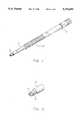
- FIG. 1is a perspective view of a micrometer surgical knife of this invention
- FIG. 2is a partial perspective, enlarged view of the distal end of the micrometer surgical knife of FIG. 1;
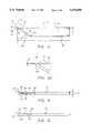
- FIGS. 3 and 3aare side plan and partial side plan views of alternative preferred surgical blades of this invention.
- FIG. 4is a top plan view of the surgical blade of FIG. 3, illustrating the sharpened vertical edge
- FIG. 5is a bottom plan view of the surgical blade of FIG. 3, illustrating the angled cutting edge
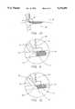
- FIGS. 6, 6a, and 6bare side plan and partial side plan views of alternative modified surgical blades of this invention having undercutting capability
- FIG. 7is an end plan view of the alternative modified surgical blade of FIG. 6;
- FIG. 8is a bottom plan view of the alternative modified surgical blade of FIG. 6, illustrating the angled cutting edge
- FIG. 9is a top plan view of the alternative modified surgical blade of FIG. 6, illustrating the sharpened vertical edge and a preferred recessed blunt side edge;
- FIG. 10is a diagrammatic side view of a radial keratotomy procedure
- FIG. 11is an enlarged view of the incision area of the keratotomy procedure illustrated in FIG. 10;
- FIG. 12is an alternative enlarged view of an incision area of a keratotomy procedure including an undercut.
- Surgical blades, knives and radial keratotomy proceduresare provided by this invention which provide ophthalmologists with equipment and techniques for corrective procedures having high efficacy with minimal risk of complications.
- keratorefractive surgical proceduresare disclosed, the surgical blades of this invention can be used for any surgical, or microsurgical application which requires maneuverability and tactile sensitivity.
- FIGS. 1-5there is shown a preferred micrometer surgical knife 100 having a blade 10 and a knife body 11.
- the bladeis affixed to the distal end 14 of the knife body 11 and is positioned at a preselected depth through the feet 12, which can be of the Russian, American, or the depicted Universal design.
- the micrometer 13is helpful for less sensitive surgical applications and gross calibration measurements. This setting is generally further fine-tuned with a calibrating microscope to provide closer tolerances for keratotomy procedures.
- a surgical blade 10is provided.
- the bladeincludes a hard, corrosion resistant material capable of being honed or lapped into a sharp cutting edge.
- materialsinclude stainless steel, glasses, ceramics, and crystalline materials containing natural or synthetic stones, such as diamonds, rubies, sapphires or similar materials of sufficient hardness.
- the stonesneed not be “gem” quality, as industrial quality stones may be sufficient in certain applications.
- the gemstonecontains a natural diamond of a grade and internal molecular structure suitable for making flat slabs with proper orientation with respect to the cleaving planes.
- the gemstoneis typically provided in a rough shape which is developed by laser cutting or sawing into a generally flat configuration. The more precise facet and cutting edge dimensions are thereafter applied to the diamond slab by cleaving and lapping.
- the preferred surgical blade 10includes a pair of longitudinal sides and a distal end containing first and second cutting edges.
- the first cutting edgeis desirably configured into an angled cutting edge 24 having a leading edge portion 27 and a trailing edge portion 21.
- the trailing edge portion 21preferably ends at the distal end portion of the blade 10.
- the angled cutting edge 24is provided by a pair of faces or facets 18 which define therebetween an angle ⁇ .
- the second cutting edgepreferably includes a sharpened vertical edge 22 which forms the distal apex of the blade 10 and tapers proximally along tapered portion 25.
- the sharpened vertical edge 22is defined by a pair of faces 16 which form therebetween an angle ⁇ .
- the term "vertical"is not limited to an edge which is perpendicular or co-planar with blunt side edge 20 or tapered portion 25, and this term is used generally to provide a comparative orientation with the disclosed angled cutting edges.
- the blunt side edge 20begins at transition point 23, and extends proximally along the second longitudinal side of the gemstone.
- the tapered portion 25is preferably defined by faces or facets 28 having an included angle of about 30°-55°.
- the tapered portion 25also presents a substantially blunt surface and may be cut to form a plane, or facet, extending at an angle of about 1°-15°, preferably about 3°-7°, from blunt side edge 20 shown in FIG. 4.
- the sharpened vertical edge 22preferably forms an angle of about +/-90° and more preferably, an acute angle ⁇ with the second longitudinal side, and preferably with the blunt side edge 20 or tapered portion 25 of the blade 10.
- the surgical blade 10further includes a length dimension C, a width dimension B and a thickness D, the preferred ranges of which are described in Table I further in this text.
- a blade 110can be provided with most of the above features, including an angled cutting edge 124 and a blunt side edge 120 situated proximally from a sharpened vertical edge 122, but with a slight taper along the entire vertical edge 122 or most of the vertical edge 122.
- the vertical edge 122preferably forms an angle ⁇ ' of about 1°-15° and more preferably about 3°-7° with the blunt side edge 120, with the faces of the vertical edge 122 and angled cutting edge forming a preferred included angle of about 25°-55°, and more preferably about 33° and 35° respectively.
- the alternative surgical blade 30includes many of the features associated with blade 10, but noticeably includes a recess, having depth measurement I, located along its second longitudinal side.
- the recessdefines a recessed blunt side edge 36 more clearly described in FIG. 9.
- Surgical blade 30, as with predecessor blade 10,further includes a sharpened vertical edge 32 which forms a piercing distal tip with angled cutting edge 34 at the distal tip of the blade 30.
- the blade 30includes an overall width F, and a recessed portion width H. The overall length of this blade is provided by measurement G, and the thickness of the blade is provided by measurement J.
- the angled cutting edge 34has a leading and trailing edge portion similar to that for blade 10, and forms an angle ⁇ ' with a perpendicular line drawn from the sharpened vertical edge 32.
- the faces of the angled cutting edge 34form an included angle ⁇ ', and the faces of the sharpened vertical edge 32 form an included angle ⁇ '.
- a blade 130can be provided having the similar features of a sharpened vertical edge 132, angled cutting edge 134, and recessed blunt side edge 136. With this particular development, however, a small radius R is provided between the sharpened vertical edge 132 and the recessed blunt side edge 136 to provide a smooth transition between these elements. In practice, this will facilitate! the removal of the knife blade 130 following redeepening of the incision.
- a blade 230can be provided with similar features of a sharpened vertical edge 232, angled cutting edge 234, and recessed blunt side edge 236.
- a taperis provided between the sharpened vertical edge 232 and the recessed blunt side edge 236. This taper can have an angle ⁇ of approximately 3°-90°.
- undercut capabilitycan be provided as with blade 30.
- blades 30, 130, and 230are easier to manufacture since the recessed blunt side edges can be configured with a laser or by conventional sawing and/or grinding methods.
- the length E of the sharpened vertical edgescan thus be more precisely and economically controlled by employing more automated methods, than by the more time-consuming and less accurate lapping wheel procedures employed to configure the cutting facets of blade 10.
- Blades 30, 130, and 230also provide heretofore unprecedented “undercut” capability, since the projected sharpened vertical edges can be directed beneath the optical zone 52, illustrated in FIG. 12, without creating optical interference or scarring at the surface of optical zone 52.
- the "optical zone”refers to the approximate 2.5-4 mm diameter section of the corneal center, or the corneal region which is immediately above the maximum pupil diameter. Undercutting must be made below the surface of the cornea, since it is believed that this will avoid surface scarring and provide tremendous corrective ability. This observation is based, in part, upon radial keratotomy procedures that have, by erroneous manipulation of the blade, transected the optical zone.
- the sharpened vertical cutting edges of this inventionare "completely" vertical (disposed at about 90° with the corneal surface), or, are less than 15°, preferably less than 8°, and ideally about 3°-7° from being completely vertical, so that they can either cut perpendicularly into the cornea, or be adjusted slightly within the blade holder to provide a vertical cutting edge.
- the recessed blunt side edge 36can be carefully configured by varying the angle ⁇ and depth I, to provide a myriad of sharpened vertical edge configurations carefully tailored to provide selected undercut and optical zone resistance capabilities.
- Preferred dimensional tolerances for the blades 10 and 30 of this inventionare provided in Table I below.
- the preferred surgical blades 10, 110, 30, 130, and 230 of this inventioninclude sharpened vertical edges 22, 122, 32, 132, and 232 and angled cutting edges 24, 124, 34, 134, and 234.
- the width measurement of the diamond blades B and H and the angles ⁇ and ⁇ 'are important parameters in determining the depth of the primary incision created by the angled cutting edges during American-style radial keratotomy procedures.
- the initial radial incisions of an American procedureare about equal to the depth of the exposed angled cutting edge. It can be readily observed that larger cutting angles ⁇ and ⁇ ' will proportionally increase the cutting depth for a given knife setting and blade width.
- the depth dimensions A and E for the preferred vertical cutting edges of these bladesare designed to lie within the broad range of about 0.05-0.35 mm.
- the lower limit, 0.05 mmis defined by the current level of manufacturing ability, and the upper limit is set at a level which will be more than sufficient to "clear up" the remainder of corneal tissue left by typical American technique procedures, but safely beneath the 0.500 mm full corneal thickness.
- An upper limit of no more than about 400 mmshould almost guarantee against superficial scarring.
- the lower limit for the vertical edgeis desirably no less than about 0.120 mm. This is due to the fact that reverse cutting edges significantly below 0.120 mm require larger ⁇ angles which render the vertical cutting edge difficult to maneuver by the surgeon. Vertical cutting edges significantly below 0.120 mm tend to plow rather than cleanly sever the corneal tissue. With such blades, if the operating surgeon does not maintain the blade precisely in the original incision, for example, if the blade is twisted or tilted from the perpendicular, the redeepening procedure may fail to retrace the bottom of the incision, and result in double cuts or additional trauma.
- the angles ⁇ and ⁇ 'generally determine the depth of penetration for the primary incision for any given setting of the surgical blade through the feet 12. It is known, for example, that sharp blades having large ⁇ angles approaching 78°, or more, can be fabricated with known manufacturing techniques, but such configurations, like blades with a large ⁇ measurement, tend to be difficult to maneuver in the cornea. Accordingly, the angled cutting edge is preferably disposed at an angle ⁇ and ⁇ ' of about 40°-60°. Such cutting edges are capable of severing through approximately 0.400-0.420 mm of the corneal tissue with a 0.500 mm setting. The redeepening procedure for these types of blades would therefore require an exposed vertical edge of something just less than about 0.080-0.100 mm.
- the knife blade 10 extending from the preferred universal feet 12is inserted into the cornea 50, and an initial incision is made starting at the optical zone 52 and cutting toward the limbus of the eye in a first direction X. Without lifting the knife, the incision is retraced in a second direction Y, to redeepen the wound.
- Thisprovides a uniform incision depth along the entire incision length, unlike the American-style incision.
- this procedureensures a more squared-off central or leading edge at the base of the wound enabling not only increased efficacy, but more predictable results as well.
- the sharpened vertical edge 22deepens the incision while the blunt side edge 20 prevents intrusion into the optical zone 52 during the retracing of the blade.
- the blade 10is carefully configured so that the sharpened vertical edge 22 of blade 10 does not enter into the optical zone 52.
- the sharpened vertical edge 32 of blade 30becomes a valuable asset.
- sharpened vertical edge 32will not only provide a redeepening of the wound, but will penetrate beneath the optical zone 52 for a distance equal to the dimension I, (assuming the knife is held substantially perpendicularly with the surface of the cornea 50), wherein contact of the edge of the optical zone 52 with recessed blunt side edge 36 prevents further penetration.
- This tunnels beneath the optical zoneto lengthen the incision at its base, thereby elongating the incision to provide a greater degree of flattening.
- this inventionprovides improved keratotomy procedures and blades for minimizing optical glare and reducing the possibility of puncturing corneal tissue.
- radial keratotomy proceduresare described, this invention would also be suitable for astigmatic and other techniques.
- the blades of this inventionare suitable for use with the American, Russian or combined techniques and provide blade designs suitable for undercutting the optical zone without causing glare.
- the specific dimensional configurationsare approximate measurements only and the disclosed ranges are applicable to all of the disclosed blade configurations, despite the fact that specific ranges are preferred for each blade.
Landscapes
- Health & Medical Sciences (AREA)
- Surgery (AREA)
- Life Sciences & Earth Sciences (AREA)
- Engineering & Computer Science (AREA)
- Ophthalmology & Optometry (AREA)
- Biomedical Technology (AREA)
- Heart & Thoracic Surgery (AREA)
- Nuclear Medicine, Radiotherapy & Molecular Imaging (AREA)
- Animal Behavior & Ethology (AREA)
- General Health & Medical Sciences (AREA)
- Public Health (AREA)
- Veterinary Medicine (AREA)
- Vascular Medicine (AREA)
- Medical Informatics (AREA)
- Molecular Biology (AREA)
- Surgical Instruments (AREA)
Abstract
Description
TABLE I __________________________________________________________________________Preferred Diamond Dimensional Ranges Genesis Modified Dimension Broad Narrow Dimension Broad Narrow __________________________________________________________________________A .050-.400 mm .120-.350 mm E .025-.400 mm .120-.350 mm (.215 mm target) (.215 mm target) B .7-2.5 mm 1 mm F .7-2.0 mm 1 mm C 3-8 mm 6 mm G 3-8 mm 6 mm D .1-.25 mm .12 mm H .695-1.5 mm .95 mm α 1-8° 3-7° I .005-1.5 mm .05 mm β 25-78° 45° J .1-.25 mm .12 mm Ω 25-45° 33° β' 25-78° 45° γ 30-55° 45° Ω' 25-45° 33° γ' 30-55° 45° __________________________________________________________________________
______________________________________ LIST OF REFERENCE NUMERALS ______________________________________ 10Blade 11Knife Body 12Feet 13Micrometer 14Distal End 16 SharpenedVertical Edge Face 18 AngledCutting Edge Face 20Blunt Side Edge 21Trailing Edge Portion 22 SharpenedVertical Edge 23Transition Point 24Angled Cutting Edge 25 TaperedPortion 26Blunt Side Edge 27Leading Edge Portion 28Tapered Portion Face 30Blade 32 SharpenedVertical Edge 34Angled Cutting Edge 36 RecessedBlunt Side Edge 50Cornea 52Optical Zone 100Micrometer Surgical Knife 110Blade 120Blunt Side Edge 122 SharpenedVertical Edge 124Angled Cutting Edge 130Blade 132 SharpenedVertical Edge 134Angled Cutting Edge 136 RecessedBlunt Side Edge 230Blade 232 SharpenedVertical Edge 234Angled Cutting Edge 236 Recessed Blunt Side Edge ______________________________________
Claims (21)
Priority Applications (1)
| Application Number | Priority Date | Filing Date | Title |
|---|---|---|---|
| US08/139,950US5376099A (en) | 1992-09-17 | 1993-10-20 | Undercut diamond surgical blade and method of using the same |
Applications Claiming Priority (3)
| Application Number | Priority Date | Filing Date | Title |
|---|---|---|---|
| US94686892A | 1992-09-17 | 1992-09-17 | |
| US96780092A | 1992-10-28 | 1992-10-28 | |
| US08/139,950US5376099A (en) | 1992-09-17 | 1993-10-20 | Undercut diamond surgical blade and method of using the same |
Related Parent Applications (1)
| Application Number | Title | Priority Date | Filing Date |
|---|---|---|---|
| US96780092ADivision | 1992-09-17 | 1992-10-28 |
Publications (1)
| Publication Number | Publication Date |
|---|---|
| US5376099Atrue US5376099A (en) | 1994-12-27 |
Family
ID=27130242
Family Applications (1)
| Application Number | Title | Priority Date | Filing Date |
|---|---|---|---|
| US08/139,950Expired - Fee RelatedUS5376099A (en) | 1992-09-17 | 1993-10-20 | Undercut diamond surgical blade and method of using the same |
Country Status (1)
| Country | Link |
|---|---|
| US (1) | US5376099A (en) |
Cited By (24)
| Publication number | Priority date | Publication date | Assignee | Title |
|---|---|---|---|---|
| US5549622A (en)* | 1995-03-10 | 1996-08-27 | Ingram; Ronald W. | Method for altering the curvature of the cornea |
| US5662668A (en)* | 1995-04-24 | 1997-09-02 | Kurwa; Badrudin | Blade for intrastromal radial keratotomy |
| US5713915A (en)* | 1996-11-15 | 1998-02-03 | Rhein Medical, Inc. | Surgical knife blade |
| US5810857A (en)* | 1993-08-12 | 1998-09-22 | Mackool; Richard J. | Surgical knife for controlled lengthening of an incision |
| US5951543A (en)* | 1997-06-30 | 1999-09-14 | Clinicon Corporation | Delivery system and method for surgical laser |
| US6023844A (en)* | 1996-03-25 | 2000-02-15 | Alcatel Na Cable Systems, Inc. | Method and cutting blade for accessing optical fibers within a buffer tube |
| US6056764A (en)* | 1998-03-18 | 2000-05-02 | Smith; Thomas C. | Opthalmic surgical blade having hard single bevel edges |
| US6077283A (en)* | 1997-04-07 | 2000-06-20 | Anton Meyer & Co. Kg | Diamond scalpel for opening the meninx |
| WO2001008570A1 (en)* | 1999-07-30 | 2001-02-08 | Drukker International Bv | A cutting blade for a surgical instrument |
| US6482219B1 (en)* | 1999-11-12 | 2002-11-19 | Richard Wolf Gmbh | Stricture scalpel |
| US20030191485A1 (en)* | 2002-04-03 | 2003-10-09 | Shimmel Jeffrey T. | Microkeratome blade |
| US20040230203A1 (en)* | 2003-05-15 | 2004-11-18 | Cuore, Inc | Intraocular device for retaining a lens capsule |
| US7166117B2 (en) | 1996-02-07 | 2007-01-23 | Hellenkamp Johann F | Automatic surgical device and control assembly for cutting a cornea |
| US20070106316A1 (en)* | 2005-10-10 | 2007-05-10 | University Of South Florida | Dural Knife with Foot Plate |
| WO2006017835A3 (en)* | 2004-08-06 | 2007-11-08 | Sightrate B V | Device for separating the epithelial layer from the surface of the cornea of eye |
| US7708750B2 (en) | 2001-07-23 | 2010-05-04 | Fos Holdings S.A. | Device for separating the epithelium layer from the surface of the cornea of an eye |
| US7780689B2 (en) | 2003-04-07 | 2010-08-24 | Technolas Perfect Vision Gmbh | Bar-link drive system for a microkeratome |
| WO2013059212A1 (en)* | 2011-10-17 | 2013-04-25 | Luttrull Jeffrey K | Microvitreoretinal surgery blades |
| US20130276607A1 (en)* | 2012-03-22 | 2013-10-24 | Brother Kogyo Kabushiki Kaisha | Cutting plotter |
| US20130283624A1 (en)* | 2012-04-26 | 2013-10-31 | Thomas Scimone | Ceramic cutting blades |
| US20150209067A1 (en)* | 2014-01-30 | 2015-07-30 | Covidien Lp | Blade Tip Profile for Use in Cutting of Tissue |
| USD741485S1 (en)* | 2012-06-07 | 2015-10-20 | Southern Implants (Pty) Ltd | Bone distractor |
| US10869715B2 (en) | 2014-04-29 | 2020-12-22 | Covidien Lp | Double bevel blade tip profile for use in cutting of tissue |
| USD972726S1 (en)* | 2021-01-11 | 2022-12-13 | Pursuit of Madness LLC | Tattoo device |
Citations (16)
| Publication number | Priority date | Publication date | Assignee | Title |
|---|---|---|---|---|
| US2049898A (en)* | 1935-04-29 | 1936-08-04 | Frederick Bishop | Surgical instrument |
| US2649860A (en)* | 1952-04-07 | 1953-08-25 | John E E Royer | Surgical instrument |
| US3945117A (en)* | 1973-02-15 | 1976-03-23 | Rudolph Beaver, Inc. | Surgical blade with adjustable blade guard |
| US4185634A (en)* | 1977-12-27 | 1980-01-29 | Freedman Bruce M | Surgical instrument |
| US4499898A (en)* | 1982-08-23 | 1985-02-19 | Koi Associates | Surgical knife with controllably extendable blade and gauge therefor |
| US4538356A (en)* | 1982-08-23 | 1985-09-03 | Koi Associates, Inc. | Surgical knife with controllably extendable blade and gauge therefor |
| US4552146A (en)* | 1982-05-18 | 1985-11-12 | Myocur, Inc. | Disposable ophthalmic instrument for performing radial keratotomy on the cornea |
| US4602630A (en)* | 1985-05-16 | 1986-07-29 | Anis Aziz Y | Radial keratotomy knife |
| US4674503A (en)* | 1981-03-05 | 1987-06-23 | Peyman Gholam A | Controlled depth penetrant apparatus and method |
| US4691716A (en)* | 1985-12-27 | 1987-09-08 | Emanuel Tanne | Automatic corneal surgery system |
| US4730613A (en)* | 1986-06-13 | 1988-03-15 | Cilco, Inc. | Surgical scalpel |
| US4750489A (en)* | 1985-08-29 | 1988-06-14 | Coopervision, Inc. | Radial keratotomy knife and system using same |
| US4768509A (en)* | 1985-12-07 | 1988-09-06 | Duckworth & Kent Surgical Instruments Limited | Surgical knife |
| US4815218A (en)* | 1986-06-13 | 1989-03-28 | Cilco, Inc. | Gauge for calibrating surgical scalpel |
| US4898170A (en)* | 1985-08-01 | 1990-02-06 | Duckworth & Kent Surgical Instruments Limited | Surgical knife |
| US5222967A (en)* | 1992-04-08 | 1993-06-29 | Magnum Diamond Corporation | Keratorefractive diamond blade and surgical method |
- 1993
- 1993-10-20USUS08/139,950patent/US5376099A/ennot_activeExpired - Fee Related
Patent Citations (17)
| Publication number | Priority date | Publication date | Assignee | Title |
|---|---|---|---|---|
| US2049898A (en)* | 1935-04-29 | 1936-08-04 | Frederick Bishop | Surgical instrument |
| US2649860A (en)* | 1952-04-07 | 1953-08-25 | John E E Royer | Surgical instrument |
| US3945117A (en)* | 1973-02-15 | 1976-03-23 | Rudolph Beaver, Inc. | Surgical blade with adjustable blade guard |
| US4185634A (en)* | 1977-12-27 | 1980-01-29 | Freedman Bruce M | Surgical instrument |
| US4674503A (en)* | 1981-03-05 | 1987-06-23 | Peyman Gholam A | Controlled depth penetrant apparatus and method |
| US4552146A (en)* | 1982-05-18 | 1985-11-12 | Myocur, Inc. | Disposable ophthalmic instrument for performing radial keratotomy on the cornea |
| US4499898A (en)* | 1982-08-23 | 1985-02-19 | Koi Associates | Surgical knife with controllably extendable blade and gauge therefor |
| US4538356A (en)* | 1982-08-23 | 1985-09-03 | Koi Associates, Inc. | Surgical knife with controllably extendable blade and gauge therefor |
| US4602630A (en)* | 1985-05-16 | 1986-07-29 | Anis Aziz Y | Radial keratotomy knife |
| US4898170A (en)* | 1985-08-01 | 1990-02-06 | Duckworth & Kent Surgical Instruments Limited | Surgical knife |
| US4750489A (en)* | 1985-08-29 | 1988-06-14 | Coopervision, Inc. | Radial keratotomy knife and system using same |
| US4768509A (en)* | 1985-12-07 | 1988-09-06 | Duckworth & Kent Surgical Instruments Limited | Surgical knife |
| US4691716A (en)* | 1985-12-27 | 1987-09-08 | Emanuel Tanne | Automatic corneal surgery system |
| US4730613A (en)* | 1986-06-13 | 1988-03-15 | Cilco, Inc. | Surgical scalpel |
| US4815218A (en)* | 1986-06-13 | 1989-03-28 | Cilco, Inc. | Gauge for calibrating surgical scalpel |
| US5222967A (en)* | 1992-04-08 | 1993-06-29 | Magnum Diamond Corporation | Keratorefractive diamond blade and surgical method |
| US5222967B1 (en)* | 1992-04-08 | 1998-01-20 | Magnum Diamond Corp | Keratorefractive diamond blade and surgical method |
Non-Patent Citations (39)
| Title |
|---|
| Article entitled "Thin-Profile Diamond Knife Blade Facilitates RK, Reduced Damage", Ophthalmology Times, p. 5 (Oct. 1, 1990). |
| Article entitled Thin Profile Diamond Knife Blade Facilitates RK, Reduced Damage , Ophthalmology Times , p. 5 (Oct. 1, 1990).* |
| Assil et al., "The Undercut Technique of Radial Keratotomy: A Comparison To The Combined Technique", Department of Ophthalmology, St. Louis University's Anheuser -Busch Eye Institute, St. Louis, Mo. |
| Assil et al., The Undercut Technique of Radial Keratotomy: A Comparison To The Combined Technique , Department of Ophthalmology, St. Louis University s Anheuser Busch Eye Institute, St. Louis, Mo.* |
| Bores, "Historical Review And Clinical Results At Radial Keratotomy", In: Binder P.S. ed. International Ophthalmology Clinics Refractive Corneal Surgery: The Correction of Aphahia, Hyperopia And Myopia, Boston, Mass.: Little, Brown and Co., 1983, 23:93-118. |
| Bores, Historical Review And Clinical Results At Radial Keratotomy , In: Binder P.S. ed. International Ophthalmology Clinics Refractive Corneal Surgery: The Correction of Aphahia, Hyperopia And Myopia, Boston, Mass.: Little, Brown and Co., 1983, 23:93 118.* |
| Buzard, "deepening of Incisions After Radial Keratotomy Using the `Tickle` Technique", Journal of Refractive & Corneal Surgery, vol. 7, pp. 348-355 (Sep./Oct. 1991). |
| Buzard, deepening of Incisions After Radial Keratotomy Using the Tickle Technique , Journal of Refractive & Corneal Surgery , vol. 7, pp. 348 355 (Sep./Oct. 1991).* |
| Codman/MICRA, "Titanium Instruments And Diamond Knives For Ophthalmology", Jan. 1985, Printed in USA, Dist. by Codman, Randolph, Mass., pp. 1-6. |
| Codman/MICRA, Titanium Instruments And Diamond Knives For Ophthalmology , Jan. 1985, Printed in USA, Dist. by Codman, Randolph, Mass., pp. 1 6.* |
| CooperVision, KOI Division, Trade Literature entitled "CooperVision KOI Freehand and Micrometer Adjustable". |
| CooperVision, KOI Division, Trade Literature entitled Blade Configurations (1986).* |
| CooperVision, KOI Division, Trade Literature entitled CooperVision KOI Freehand and Micrometer Adjustable .* |
| CooperVision, KOI Division, Trade Literature entitled KOI Freehand Diamond Knife (Copyright 1985).* |
| Diamond Knives Designed Specifically for Cutting Corneal Tissue (1985).* |
| Herbert, "The Diamond Knife-Rather More Than Meets The Eye", Industrial Diamond Review, May 1984. |
| Herbert, The Diamond Knife Rather More Than Meets The Eye , Industrial Diamond Review, May 1984.* |
| International Facilities Corporation Trade Literature, Microsurgical Diamond Knife (undated).* |
| Kmi, Inc. Diamond blade configurations styles 18, 19, 24, 33, 3, 4, and 8, distributed during the 1980 s.* |
| Kmi, Inc. Diamond blade configurations styles 18, 19, 24, 33, 3, 4, and 8, distributed during the 1980's. |
| KMI, Inc. Trade Literature entitled "Multi-purpose KMI Freehand Diamond Knife is Ideal for Most Incisions" (1987). |
| KMI, Inc. Trade Literature entitled Cataract and General Surgery Diamond Knives and Micrometer Diamond Surgical Knives (1989).* |
| KMI, Inc. Trade Literature entitled Diamond Surgical Knives (1988).* |
| KMI, Inc. Trade Literature entitled KMI Surgical Products Introduces a New Concept in Diamond Knives (1989).* |
| KMI, Inc. Trade Literature entitled Micrometer Diamond Knives (1991).* |
| KMI, Inc. Trade Literature entitled Multi purpose KMI Freehand Diamond Knife is Ideal for Most Incisions (1987).* |
| KMI, Inc. Trade Literature entitled Ophthalmology Update (Mar., 1988).* |
| KMI, Inc. Trade Literature, "KMI `gems`are always in the right setting . . ." (1992). |
| KMI, Inc. Trade Literature, Genesis. the Beginning of Safe Keratorefractive Surgery (1992).* |
| KMI, Inc. Trade Literature, KMI gems are always in the right setting . . . (1992).* |
| KMI, Inc. Trade Literature, Radial and Astigmatic Keratotomy Instruments (1992).* |
| KOI Trade Literature entitled Diamond Knife Configurations (1990).* |
| KOI Trade Literature entitled KOI Diamond Micrometers (1991).* |
| Melles, et al., "Effect of Radial Keratotomy Incision Direction on Wound Depth", Journal of Refractive & Corneal Surgery, vol. 6, pp. 394-403 (Nov./Dec. 1990). |
| Melles, et al., Effect of Radial Keratotomy Incision Direction on Wound Depth , Journal of Refractive & Corneal Surgery , vol. 6, pp. 394 403 (Nov./Dec. 1990).* |
| Merlin et al., "Factors That Affect Keratotomy Depth", Journal of Refractive & Corneal Surgery, vol. 7, pp. 356-359 (Sep./Oct. 1991). |
| Merlin et al., Factors That Affect Keratotomy Depth , Journal of Refractive & Corneal Surgery , vol. 7, pp. 356 359 (Sep./Oct. 1991).* |
| Waring, "Repeated Surgery For Residual Myopia And Hyperopia After Refractive Corneal Surgery", In: Waring G. O. ed. Refractive Keratotomy For Myopia And Astigmatism, St. Louis, Mo., Musby Yearbook Inc., 1991, pp. 641-668. |
| Waring, Repeated Surgery For Residual Myopia And Hyperopia After Refractive Corneal Surgery , In: Waring G. O. ed. Refractive Keratotomy For Myopia And Astigmatism, St. Louis, Mo., Musby Yearbook Inc., 1991, pp. 641 668.* |
Cited By (31)
| Publication number | Priority date | Publication date | Assignee | Title |
|---|---|---|---|---|
| US5810857A (en)* | 1993-08-12 | 1998-09-22 | Mackool; Richard J. | Surgical knife for controlled lengthening of an incision |
| US5549622A (en)* | 1995-03-10 | 1996-08-27 | Ingram; Ronald W. | Method for altering the curvature of the cornea |
| US5662668A (en)* | 1995-04-24 | 1997-09-02 | Kurwa; Badrudin | Blade for intrastromal radial keratotomy |
| US7166117B2 (en) | 1996-02-07 | 2007-01-23 | Hellenkamp Johann F | Automatic surgical device and control assembly for cutting a cornea |
| US6023844A (en)* | 1996-03-25 | 2000-02-15 | Alcatel Na Cable Systems, Inc. | Method and cutting blade for accessing optical fibers within a buffer tube |
| US5713915A (en)* | 1996-11-15 | 1998-02-03 | Rhein Medical, Inc. | Surgical knife blade |
| USRE37304E1 (en) | 1996-11-15 | 2001-07-31 | Rhein Medical, Inc. | Surgical knife blade |
| US6077283A (en)* | 1997-04-07 | 2000-06-20 | Anton Meyer & Co. Kg | Diamond scalpel for opening the meninx |
| US5951543A (en)* | 1997-06-30 | 1999-09-14 | Clinicon Corporation | Delivery system and method for surgical laser |
| US6056764A (en)* | 1998-03-18 | 2000-05-02 | Smith; Thomas C. | Opthalmic surgical blade having hard single bevel edges |
| WO2001008570A1 (en)* | 1999-07-30 | 2001-02-08 | Drukker International Bv | A cutting blade for a surgical instrument |
| US6482219B1 (en)* | 1999-11-12 | 2002-11-19 | Richard Wolf Gmbh | Stricture scalpel |
| US7708750B2 (en) | 2001-07-23 | 2010-05-04 | Fos Holdings S.A. | Device for separating the epithelium layer from the surface of the cornea of an eye |
| US20030191485A1 (en)* | 2002-04-03 | 2003-10-09 | Shimmel Jeffrey T. | Microkeratome blade |
| US6805698B2 (en)* | 2002-04-03 | 2004-10-19 | Alcon, Inc. | Microkeratome blade |
| US6811556B2 (en) | 2002-04-03 | 2004-11-02 | Alcon, Inc. | Microkeratome blade |
| WO2003092544A3 (en)* | 2002-04-03 | 2007-11-22 | Alcon Inc | Microkeratome blade |
| US7780689B2 (en) | 2003-04-07 | 2010-08-24 | Technolas Perfect Vision Gmbh | Bar-link drive system for a microkeratome |
| US20040230203A1 (en)* | 2003-05-15 | 2004-11-18 | Cuore, Inc | Intraocular device for retaining a lens capsule |
| US8038684B2 (en) | 2003-05-15 | 2011-10-18 | Showa University | Intraocular device for retaining a lens capsule |
| WO2006017835A3 (en)* | 2004-08-06 | 2007-11-08 | Sightrate B V | Device for separating the epithelial layer from the surface of the cornea of eye |
| US20070106316A1 (en)* | 2005-10-10 | 2007-05-10 | University Of South Florida | Dural Knife with Foot Plate |
| WO2013059212A1 (en)* | 2011-10-17 | 2013-04-25 | Luttrull Jeffrey K | Microvitreoretinal surgery blades |
| US9308018B2 (en) | 2011-10-17 | 2016-04-12 | Jeffrey K. Luttrull | Microvitreoretinal surgery blades |
| US20130276607A1 (en)* | 2012-03-22 | 2013-10-24 | Brother Kogyo Kabushiki Kaisha | Cutting plotter |
| US20130283624A1 (en)* | 2012-04-26 | 2013-10-31 | Thomas Scimone | Ceramic cutting blades |
| US9662796B2 (en)* | 2012-04-26 | 2017-05-30 | Thomas Scimone | Ceramic cutting blades |
| USD741485S1 (en)* | 2012-06-07 | 2015-10-20 | Southern Implants (Pty) Ltd | Bone distractor |
| US20150209067A1 (en)* | 2014-01-30 | 2015-07-30 | Covidien Lp | Blade Tip Profile for Use in Cutting of Tissue |
| US10869715B2 (en) | 2014-04-29 | 2020-12-22 | Covidien Lp | Double bevel blade tip profile for use in cutting of tissue |
| USD972726S1 (en)* | 2021-01-11 | 2022-12-13 | Pursuit of Madness LLC | Tattoo device |
Similar Documents
| Publication | Publication Date | Title |
|---|---|---|
| US5376099A (en) | Undercut diamond surgical blade and method of using the same | |
| US5713915A (en) | Surgical knife blade | |
| US5201747A (en) | Ophthalmological surgical instrument having a triple edge tip | |
| US6139559A (en) | Surgical blade | |
| US4298004A (en) | Surgical method for altering the curvature of the cornea of rabbits | |
| US5222967A (en) | Keratorefractive diamond blade and surgical method | |
| US5224950A (en) | Color calibrated multi-function scalpel blade for intraocular and other surgery and associated methods of use | |
| US6908471B2 (en) | Ophthalmologic knife | |
| US5370652A (en) | Surgical knife blade for making sutureless incisions in the eye and methods therefor | |
| WO1993006800A1 (en) | Eye surgery knife blade and method | |
| JPH09103485A (en) | Hypodermic cannula | |
| US5571124A (en) | Apparatus and method for performing surgery on the cornea of an eye | |
| US5199445A (en) | Stromal puncture method | |
| CA2580724C (en) | Surgical knife blade with hollow bevel | |
| US5336236A (en) | Surgical knife and method for performing radial keratotomy enhancement surgery | |
| US6547802B1 (en) | Surgical blade | |
| JP6058267B2 (en) | Medical knife | |
| US5700274A (en) | Refractive surgery knife | |
| US5458610A (en) | Refractive surgery knife and process | |
| US20170319230A1 (en) | Skin surgery knife | |
| WO1994009710A1 (en) | Diamond surgical blade | |
| US6966921B2 (en) | Device for radial optic neurotomy | |
| US20050131435A1 (en) | Microkeratome cutting-head for use with a single-bevel cutting-blade assembly | |
| CN115105290A (en) | Improve ophthalmic surgery sword of maneuverability | |
| US5662668A (en) | Blade for intrastromal radial keratotomy |
Legal Events
| Date | Code | Title | Description |
|---|---|---|---|
| AS | Assignment | Owner name:KMI, INC., PENNSYLVANIA Free format text:ASSIGNMENT OF ASSIGNORS INTEREST;ASSIGNORS:KNEPSHIELD, WILLIAM R.;FAY, KRISTEN S.;REEL/FRAME:006754/0166 Effective date:19931015 | |
| AS | Assignment | Owner name:KMI, INC., PENNSYLVANIA Free format text:LICENSE;ASSIGNORS:FAY, KRISTEN;KNEPSHIELD, WILLIAM, SR.;REEL/FRAME:007322/0099 Effective date:19941014 Owner name:FAY, KRISTEN, PENNSYLVANIA Free format text:ASSIGNMENT OF ASSIGNORS INTEREST;ASSIGNOR:KMI, INC.;REEL/FRAME:007319/0430 Effective date:19941014 Owner name:KNEPSHIELD, WILLIAM, SR., PENNSYLVANIA Free format text:ASSIGNMENT OF ASSIGNORS INTEREST;ASSIGNOR:KMI, INC.;REEL/FRAME:007319/0430 Effective date:19941014 | |
| LAPS | Lapse for failure to pay maintenance fees | ||
| FP | Lapsed due to failure to pay maintenance fee | Effective date:19981227 | |
| STCH | Information on status: patent discontinuation | Free format text:PATENT EXPIRED DUE TO NONPAYMENT OF MAINTENANCE FEES UNDER 37 CFR 1.362 |