US5376084A - Catheter with internal mandrel and method - Google Patents
Catheter with internal mandrel and methodDownload PDFInfo
- Publication number
- US5376084A US5376084AUS07/779,356US77935691AUS5376084AUS 5376084 AUS5376084 AUS 5376084AUS 77935691 AUS77935691 AUS 77935691AUS 5376084 AUS5376084 AUS 5376084A
- Authority
- US
- United States
- Prior art keywords
- mandrel
- distal end
- end portion
- catheter body
- catheter
- Prior art date
- Legal status (The legal status is an assumption and is not a legal conclusion. Google has not performed a legal analysis and makes no representation as to the accuracy of the status listed.)
- Expired - Fee Related
Links
- 238000000034methodMethods0.000titleclaimsdescription32
- 210000003101oviductAnatomy0.000claimsdescription30
- 210000004291uterusAnatomy0.000claimsdescription12
- 230000002093peripheral effectEffects0.000claimsdescription7
- 210000003679cervix uteriAnatomy0.000claimsdescription5
- 230000000694effectsEffects0.000claimsdescription2
- 238000010276constructionMethods0.000description6
- 238000003780insertionMethods0.000description6
- 230000037431insertionEffects0.000description6
- 238000013459approachMethods0.000description3
- 230000008901benefitEffects0.000description3
- 239000000463materialSubstances0.000description3
- 229920001296polysiloxanePolymers0.000description3
- 239000000994contrast dyeSubstances0.000description2
- 208000015181infectious diseaseDiseases0.000description2
- 238000002347injectionMethods0.000description2
- 239000007924injectionSubstances0.000description2
- 229910001220stainless steelInorganic materials0.000description2
- 239000010935stainless steelSubstances0.000description2
- 239000004677NylonSubstances0.000description1
- 240000007817Olea europaeaSpecies0.000description1
- 239000004698PolyethyleneSubstances0.000description1
- 239000004809TeflonSubstances0.000description1
- 229920006362Teflon®Polymers0.000description1
- 239000000853adhesiveSubstances0.000description1
- 230000001070adhesive effectEffects0.000description1
- 238000002399angioplastyMethods0.000description1
- 239000000560biocompatible materialSubstances0.000description1
- 210000000746body regionAnatomy0.000description1
- 229940039231contrast mediaDrugs0.000description1
- 239000002872contrast mediaSubstances0.000description1
- 238000001816coolingMethods0.000description1
- 238000007887coronary angioplastyMethods0.000description1
- 210000004351coronary vesselAnatomy0.000description1
- 230000008878couplingEffects0.000description1
- 238000010168coupling processMethods0.000description1
- 238000005859coupling reactionMethods0.000description1
- 239000003814drugSubstances0.000description1
- 229940079593drugDrugs0.000description1
- 210000002257embryonic structureAnatomy0.000description1
- 238000011156evaluationMethods0.000description1
- 210000001105femoral arteryAnatomy0.000description1
- 239000012530fluidSubstances0.000description1
- 239000002783friction materialSubstances0.000description1
- 238000010438heat treatmentMethods0.000description1
- 238000001802infusionMethods0.000description1
- 230000002262irrigationEffects0.000description1
- 238000003973irrigationMethods0.000description1
- 239000007788liquidSubstances0.000description1
- 238000012986modificationMethods0.000description1
- 230000004048modificationEffects0.000description1
- 229920001778nylonPolymers0.000description1
- -1polyethylenePolymers0.000description1
- 229920000573polyethylenePolymers0.000description1
- 229920002635polyurethanePolymers0.000description1
- 239000004814polyurethaneSubstances0.000description1
- 102000004169proteins and genesHuman genes0.000description1
- 108090000623proteins and genesProteins0.000description1
- 230000000717retained effectEffects0.000description1
- 238000006467substitution reactionMethods0.000description1
- 239000012815thermoplastic materialSubstances0.000description1
- 229920001187thermosetting polymerPolymers0.000description1
- 230000000007visual effectEffects0.000description1
Images


Classifications
- A—HUMAN NECESSITIES
- A61—MEDICAL OR VETERINARY SCIENCE; HYGIENE
- A61M—DEVICES FOR INTRODUCING MEDIA INTO, OR ONTO, THE BODY; DEVICES FOR TRANSDUCING BODY MEDIA OR FOR TAKING MEDIA FROM THE BODY; DEVICES FOR PRODUCING OR ENDING SLEEP OR STUPOR
- A61M25/00—Catheters; Hollow probes
- A61M25/0021—Catheters; Hollow probes characterised by the form of the tubing
- A61M25/0041—Catheters; Hollow probes characterised by the form of the tubing pre-formed, e.g. specially adapted to fit with the anatomy of body channels
- A—HUMAN NECESSITIES
- A61—MEDICAL OR VETERINARY SCIENCE; HYGIENE
- A61M—DEVICES FOR INTRODUCING MEDIA INTO, OR ONTO, THE BODY; DEVICES FOR TRANSDUCING BODY MEDIA OR FOR TAKING MEDIA FROM THE BODY; DEVICES FOR PRODUCING OR ENDING SLEEP OR STUPOR
- A61M2210/00—Anatomical parts of the body
- A61M2210/14—Female reproductive, genital organs
- A—HUMAN NECESSITIES
- A61—MEDICAL OR VETERINARY SCIENCE; HYGIENE
- A61M—DEVICES FOR INTRODUCING MEDIA INTO, OR ONTO, THE BODY; DEVICES FOR TRANSDUCING BODY MEDIA OR FOR TAKING MEDIA FROM THE BODY; DEVICES FOR PRODUCING OR ENDING SLEEP OR STUPOR
- A61M25/00—Catheters; Hollow probes
- A61M25/01—Introducing, guiding, advancing, emplacing or holding catheters
- A61M25/0105—Steering means as part of the catheter or advancing means; Markers for positioning
- A61M25/0133—Tip steering devices
- A61M25/0152—Tip steering devices with pre-shaped mechanisms, e.g. pre-shaped stylets or pre-shaped outer tubes
Definitions
- a catheterinserted through either a natural body orifice or through an incision.
- a catheteris inserted through the femoral artery to the desired region of the heart where the angioplasty procedure is carried out.
- the catheterhas a preshaped distal end portion of a configuration designed to facilitate reaching the desired region of the heart.
- a guide wireis used, and the guide wire straightens the preshaped distal end portion.
- the wireis removed so the distal end portion of the catheter can return to its preformed shape to facilitate access to the desired coronary artery.
- a similar approachis used in catheterizing the fallopian tubes utilizing a transcervical approach. For example, it may be necessary or desirable to access the fallopian tubes for the infusion of a contrast dye for fluoroscopic evaluation, the placement of another catheter in which embryos, zygotes or other genetic material are deposited within the fallopian tubes, the canulation of guide wires for tubal occlusions and the insertion of an endoscope.
- One prior art approachutilizes a single-lumen catheter having a curved distal end portion in the unstressed condition.
- a mandrelis passed through the through lumen to straighten and stiffen the catheter.
- the catheteris passed through the cervix, and the catheter is oriented in the direction of the desired ostium. Once oriented, the mandrel is removed completely from the catheter, and this allows the catheter to return to its preformed, curved shape. A medical procedure can then be carried out through the lumen.
- This inventionreduces the time and complexity of a catheterization procedure of the type requiring the use of a mandrel to alter the shape of a preformed distal end portion of a catheter body. In addition, for certain procedures the risk of infection and cost are also reduced. Although this invention is particularly applicable to catheterization of a fallopian tube, some of the features of this invention have other applications.
- This inventionmay be embodied in a catheter which includes an elongated, flexible catheter body having a distal end portion which is of a first configuration in an unstressed condition.
- the catheter bodyhas a first lumen, which is typically a through lumen, that extends into the distal end portion and opens at a distal opening in the distal end portion.
- the catheteralso includes a mandrel having a distal end portion of a second configuration which is different from the first configuration.
- the distal end portion of the mandrelhas sufficient strength to alter the first configuration of the catheter body, and preferably it has sufficient strength to substantially conform the distal end portion of the catheter body to the second configuration.
- the catheter bodyhas a separate mandrel lumen.
- the mandrelis movable in the mandrel lumen between an extended position in which the distal end portion of the mandrel is sufficiently within the distal end portion of the catheter body to alter the first configuration of the distal end portion of the catheter body and a retracted position in which the mandrel is located proximally of the position the mandrel occupies in the extended position, and the distal end portion of the catheter is altered less than in the extended position.
- the through lumenis unobstructed by the mandrel, and the mandrel can remain in the catheter during the entire procedure.
- the mandrelneed not be withdrawn in order for another instrument, such as an endoscope, to be inserted through the through lumen.
- the mandrelcan be easily re-employed to again alter the unstressed configuration of the distal end portion.
- the unstressed first configuration of the distal end portion of the cathetercan be any configuration which is required in order to access the desired body region.
- the distal end portion of the catheter bodyin an unstressed condition, is deflected with respect to a contiguous region of the catheter body.
- the mandrelhas a distal end portion which is configured to alter this unstressed first configuration of the distal end portion of the catheter body.
- the deflection of the distal end portion of the catheter bodymay be provided by one or more curves or sharp bends in the same or different planes.
- the unstressed or preformed configurationis preferably curved.
- the mandrelmay partially or totally straighten the curve.
- the mandrelpreferably substantially straightens the curve so that the catheter body is substantially straightened and stiffened for passage into the uterus.
- the mandrelIn the retracted position, the mandrel may exert substantially no effect on the shape of the distal end portion of the catheter body.
- the catheterpreferably includes a control slide mounted on the catheter body for movement longitudinally of the catheter body.
- the control slidecan move the mandrel between the extended and retracted positions. This can also be relatively easily accomplished with one hand thereby freeing the other hand of the physician for other tasks.
- the control slidefacilitates accurate movement of the mandrel the precisely correct amount to achieve the desired distal end portion configuration for the catheter body.
- the mandrelhas a distal end and a distal region that terminates at the distal end.
- the distal regionis deflected with respect to a contiguous region of the distal end portion of the mandrel in a way to facilitate movement of the mandrel along the distal end portion.
- the distal region of the mandrelmay have various different configurations. For some applications, it may desirable to employ a mandrel which terminates distally in an enlarged, round tip.
- the catheter bodyhas a peripheral wall with an opening proximally of the distal end portion of the catheter body.
- the openingleads to the mandrel lumen, and the mandrel exits through the opening.
- the control slideis employed, it is preferably coupled to the mandrel at a proximal end of the mandrel which lies outside of the opening.
- the catheterincludes means for preventing the mandrel from being completely withdrawn from the mandrel lumen through the opening.
- such meansincludes the control slide and the attachment of the mandrel to the control slide.
- such meansmay take other forms, such as a stop on the mandrel which prevents its full withdrawal through the opening whether such opening is on the peripheral wall of the catheter body or at the proximal end of the catheter body.
- the movement of the mandrel longitudinally within the mandrel lumenis preferably limited by stops.
- the rear or proximal stopprevents complete withdrawal of the mandrel from the mandrel lumen.
- the forward or distal stoplimits the forward or distal movement of the mandrel. This is important to assure that the mandrel does not project beyond the distal end of the catheter body where it could injure the patient.
- the mandrel lumenterminates distally in an end wall which would also tend to prevent extension of the mandrel distally beyond the distal end of the catheter body. However, even if the end wall is provided, the distal stop prevents movement of the mandrel distally to a position in which the mandrel would contact the end wall.
- An everting-type catheteris characterized by an elongated inner member having a distal end portion and a flexible everting element coupled to the distal end portions of the inner member and the catheter body.
- the provision of a dedicated, separate mandrel lumenis particularly important in this type of catheter to assure that the mandrel does not rupture the thin, flexible everting element.
- the distal end portion of the catheterwhich has been substantially straightened by the mandrel, is inserted through the cervix and into the uterus.
- the mandrelis then retracted to the retracted position without removing the mandrel from the mandrel lumen to allow the distal end portion of the catheter body to assume its unstressed configuration.
- the distal opening of the through lumenis then directed toward one ostium, and a medical procedure, which may involve examination and/or treatment, is carried out through the through lumen in the fallopian tube associated with that ostium.
- both ostiaare involved, the mandrel is advanced to the extended position without withdrawing the catheter body from the uterus, and the catheter body is oriented generally about its longitudinal axis. The mandrel is then retracted to the retracted position without removing the mandrel from the mandrel lumen and without withdrawing the catheter body from the uterus. The distal opening of the through lumen is then directed toward the other ostium, and a procedure, which may involve examination and/or treatment, is carried out in the fallopian tube associated with that ostium utilizing the through lumen. With this method, both ostia are accessed with a single catheter without having to withdraw either the mandrel from the catheter body or the catheter from the uterus.
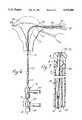
- FIG. 1is a plan view of a catheter constructed in accordance with the teachings of this invention with the catheter body being straightened and inserted into the uterus of a patient.
- FIG. 2is a plan view similar to FIG. 1 with the distal end portion of the catheter in the curved configuration.
- FIG. 3is an enlarged, fragmentary view partially in section of a portion of the catheter with the catheter body being in a straightened condition.
- FIG. 4is a view similar to FIG. 3, with the catheter body being in the curved configuration.
- FIG. 4Ais an enlarged, fragmentary side elevational view of a distal segment of a mandrel of an alternate configuration.
- FIG. 5is an enlarged, fragmentary, sectional view taken generally along line 5--5 of FIG. 3.
- FIG. 6is a plan view similar to FIG. 1 with the everting element everted into one of the fallopian tubes.
- FIG. 7is an enlarged, fragmentary, sectional view taken on a longitudinal plane of a distal region of the catheter and with the everting member inverted within the catheter body.
- FIG. 8is a sectional view similar to FIG. 7 with the everting element everted out of the distal end of the catheter body.
- FIG. 9is an enlarged, fragmentary sectional view taken on an axial plane with the mandrel in the retracted position.
- FIG. 1shows a catheter 11 which generally comprises a catheter body 13, a mandrel 15 (FIGS. 1-5), a control slide 17, a catheter body fitting 19, an inner member in the form of an inner catheter tube 21, an inner tube fitting 23 and an everting element 25 (FIGS. 7 and 8).
- the catheter body 13is elongated and flexible and includes a main body 27 (FIGS. 7 and 8) and a tip member 29 affixed to the distal end of the main body.
- the through lumen 31extends all the way through the catheter body 13 from a proximal end of the catheter body at the catheter body fitting 19 to a distal end 35 (FIGS. 7 and 8) where the through lumen opens at a distal opening 37.
- the mandrel lumen 33terminates in an end wall 39 (FIGS. 7 and 8).
- the lumens 31 and 33are preferably, but not necessarily, completely isolated from each other by a wall 41 (FIGS. 5, 7
- the tip member 29is preferably bonded to the main body 27 (FIGS. 7 and 8).
- the entire catheter body 13is constructed of a suitable biocompatible material.
- the main body 27may be constructed of a flexible, biocompatible polymeric material, such as nylon, polyethylene, polyurethane or silicone.
- the tip member 29is preferably constructed of a soft, biocompatible polymeric material, such as silicone.
- the catheter 11is a linear everting catheter, and as such, includes not only the inner tube 21, but also the thin, flexible everting element 25.
- the everting element 25is bonded to the distal end portion of the inner tube 21 and to an inner surface of the tip member 29 as shown in FIGS. 7 and 8. This causes the everting element 25 to fold as shown in these figures adjacent the distal end portion of the inner tube 21.
- Linear everting cathetersare known, and the manner of attachment of the everting element 25 to the inner tube 21 and the tip member 29 may be carried out in accordance with known procedures.
- the everting element 25 and the inner tube 21can be moved between the positions of FIGS. 7 and 8 by controlling the pressure within the everting element 25 while simultaneously manually moving the inner tube 21 in a manner known in the art.
- the inner tube 21may be of various different constructions. However, the inner tube 21 preferably has a relatively rigid proximal section 40 (FIGS. 1 and 2), which may be constructed of stainless steel, and a flexible distal section 42 (FIG. 8) which is constructed of a suitable biocompatible, flexible polymeric material.
- the sections 40 and 42are suitably joined together as by an adhesive at a location 44 (FIG. 1) so that at least the portion of the inner tube 21 which extends through the curved, distal end portion 43, which is described below, is flexible.
- the precise position of the location 44is not critical.
- the catheter body 13has a distal end portion 43 of a preformed configuration.
- the preformed configurationis different from the configuration of the region of the catheter body 13 which is contiguous to the distal end portion 43 and is deflected with respect to such region.
- the distal end portion 43is curved in an unstressed condition. More specifically, in the illustrated embodiment, the curve forms a portion of a circular arc which may extend through, for example, up to about 90 degrees. In the drawings, the arc through which the curve extends approximates 90 degrees, but this is merely illustrative as an arc of 65 to 75 degrees is also suitable as are arcs of other lengths.
- the curvemay be provided to the distal end portion 43 in any conventional way, such as by utilizing a thermoplastic material for the catheter body 13, heating the distal end portion in a mold or die of the desired shape and then cooling the distal end portion. If a thermosetting plastic is used, the distal end portion 43 can be molded to the desired configuration. 0f course, the distal end portion 43 may be constructed integrally with the remainder of the catheter body 13 or as a separate member and then attached to the remainder of the catheter body 13.
- the catheter body 13has a series of longitudinally spaced, annular depth markings 46.
- the mandrel 15'is an elongated, flexible member which may be constructed, for example, of 304 series stainless steel spring-tempered wire. Although the mandrel 15 is flexible, it possesses sufficient rigidity to alter, and in this specific embodiment, straighten the preformed configuration of the distal end portion 43 of the catheter body 13.
- the mandrel 15has a distal end portion 45 which is configured to alter and, in the illustrated embodiment, straighten the distal end portion 43 of the catheter body 13.
- the distal end portion 45 of the mandrel 15is straight and linear, except for a distal region 47 (FIG. 9) of the mandrel.
- the distal region 47is angularly deflected with respect to the contiguous region of the distal end portion 45 of the mandrel 15.
- the mandrel 15is within the mandrel lumen 33 and is movable longitudinally in that lumen between the extended position shown in FIGS. 1 and 3 and the retracted position shown in FIGS. 2, 4 and 9.
- the purpose for the angularly deflected distal region 47is to facilitate movement of the mandrel 15 through the mandrel lumen 33 along the distal end portion 43 of the catheter body 13.
- the mandrel 15 and the distal region 47 thereofcan be of various different constructions depending on the cross-sectional area of the mandrel lumen 33, stiffnesses of the mandrel 15 and the catheter body 13 and the shape of the distal end portion 43 in the unstressed condition, in one preferred construction, the mandrel has a diameter of about 0.022 inch, and the distal region has a length of no greater than about 0.080 inch and no less than about 0.020 inch. Lengths greater than 0.080 inch tend to undesirably increase the friction between the distal region 47 and the wall of the mandrel lumen 33, and lengths under 0.020 inch tend to reduce the benefit of the deflected distal region 47.
- the distal region 47can be curved, preferably, it is simply bent through an angle with respect to the contiguous portion of the mandrel 15. This angle is preferably at least about 15 degrees in order to provide the reduced friction benefit and preferably not over 45 degrees because angles greater than 45 degrees tend to require a larger cross-sectional area mandrel lumen 33 than is desired.
- the mandrel 15preferably terminates in a rounded, full radius, ball-like distal end 49 and is coated with low-friction material, such as a silicone or Teflon.
- FIG. 4Ashows a mandrel 15a which is identical to the mandrel 15 in all respects not shown or described herein.
- the only difference between the mandrels 15 and 15ais that the latter has an enlarged, rounded distal tip 50 in lieu of the deflected distal region 47.
- the distal tip 50is essentially spherical and forms a ball; however, other rounded configurations, such as tear drop or olive configurations may also be used.
- the catheter body 13has an opening 51 (FIGS. 4 and 9) in its peripheral wall 53 with the opening being proximally of the distal end portion 43.
- the opening 51leads to the mandrel lumen 33, and the mandrel 15 extends through the opening 51 as shown in FIGS. 4 and 9 whereby the mandrel extends to the exterior of the catheter body 13.
- the mandrel 15has a proximal segment 55 which extends radially outwardly and is received in a corresponding recess in the control slide 17.
- the attachment of the mandrel 15 to the control slide 17accomplishes two important results. First, by moving the control slide 17 longitudinally on the catheter body 13, the mandrel 15 can be moved between the extended position of FIGS. 1 and 3 and the retracted position of FIGS. 2, 4 and 9. Moreover, this movement can be easily accomplished using only one hand of the physician. Secondly, the attachment of the mandrel 15 to the control slide 17 prevents rotation of the mandrel 15 about its longitudinal axis so that the distal region 47 cannot rotate substantially out of the planar region in which it is placed. Accordingly, this enables the distal end portion 43 of the catheter body 13 and the distal region 47 of the mandrel 15 to be retained in substantially the same planar region. By maintaining this orientation, the deflected distal region 47 is better able to travel through the curved mandrel lumen 33.
- control slide 17can be of various different configurations, in the illustrated embodiment, it is a tubular member which slidably receives the catheter body 13.
- the catheter body fitting 19forms a stop which limits the travel of the control slide 17 proximally to thereby prevent the mandrel 15 from being completely withdrawn from the mandrel lumen 33 through the opening 51.
- the mandrel 15is an integral part of the catheter 11.
- stopscan be provided, such as an enlargement on the mandrel 15 which is too large to pass through the opening 51.
- the movement of the control slide 17 distallyis also limited, and in this embodiment, it is limited by the mandrel 15 and the opening 51 reaching the position shown in FIG. 3.
- the opening 51is in the form of a circumferentially narrow hole having a short dimension so that the mandrel 15 will easily pass through the opening.
- the opening 51may be in the form of a much longer elongated slot, and in this event, the direction of elongation of the slot may be in the direction of elongation of the catheter body 13.
- the fittings 19 and 23may each be in the form of T-adapters, and they have legs 57 and 59, respectively, which are coupled to the proximal ends of the catheter body 13 and the inner tube 21, respectively.
- the fittings 19 and 23also have injection legs 61 and 63, respectively, for the injection of an appropriate media.
- the media injected through the legs 61 and 63may be either a liquid or a gas.
- the media that is injected through the leg 61may be an inflation media for inflating the everting element 15 or a contrast media.
- the leg 63can be used, for example, for irrigation fluid, a contrast dye, drugs or for aspiration.
- any media infused through the leg 63passes through the inner tube 21 and out through the distal end 65 (FIG. 8) of the inner tube.
- the media injected through the leg 61enters the through lumen 31 outside of the inner tube 21 and travels to the everting element 25 (FIGS. 7 and 8).
- the fittings 19 and 23have third legs 67 and 69, respectively.
- the third leg 67has a seal 70 which prevents the media injected through the leg 61 from passing out through the leg 67 and which provides a sliding fit with the inner tube 21 to allow it to be moved along with the fitting 23 both proximally and distally with respect to the fitting 19.
- the leg 69provides a port for the introduction of any of a variety of medical instruments, such as an endoscope for viewing of the fallopian tubes. Both of the fittings 19 and 23 may be conventional.
- the control slide 17is moved distally to the position of FIGS. 1 and 3 to move the mandrel 15 through the curved portion of the mandrel lumen 33 to the extended position in which the mandrel straightens, or substantially straightens, the distal end portion 43 of the catheter body to provide the substantially straightened catheter body shown in these figures.
- the distal end portion 43 of the substantially straightened catheter body 13is inserted through the cervix 71 of a patient into the uterus 73 to the position shown in FIG. 1 in which the distal end 35 contacts or is near the fundus 75.
- the depth markings 46reveal the depth of insertion of the catheter body 13.
- the mandrel 15not only straightens the curved distal end portion 43, but also provides added rigidity to the distal end portion 43 for the insertion process.
- the mandrel 15is then retracted in the mandrel lumen 33 to a retracted position shown in FIGS. 2 and 4 in which the mandrel is positioned proximally of the distal end portion 43. Consequently, the distal end portion 43 of the catheter body 13 is allowed to return to its naturally curved condition.
- This retraction of the mandrel 15is carried out without removing the mandrel from the mandrel lumen 33.
- the distal end 49 of the mandrel 15is sufficiently advanced within the catheter body 13 to be within the uterus even when it is in the retracted position so it can provide the desired rigidity for further manipulation of the catheter body 13 as may be desired.
- the insertion processis carried out so that, when the mandrel 15 is retracted, the distal end portion 43, and in particular the distal opening 37 of the through lumen 31, will be directed toward one ostium 77 of one of the fallopian tubes 79.
- the catheter bodymay be manipulated during or following the insertion step as by rotating the catheter body 13 about its longitudinal axis to bring about the desired orientation of the distal end 35 and the ostium 77.
- the everting element 25is everted as shown in FIG. 6 so it extends for a distance into the fallopian tube 79.
- the eversion of the everting element 25is carried out in a known manner which includes introducing an inflation medium through the leg 61 into the interior of the everting element and advancing the fitting 23 and, hence inner tube 21, in the catheter body 13 as may be desired to control the eversion process in a known manner.
- a medical procedurecan be carried out in the fallopian tube through the through lumen 31.
- an elongated, flexible endoscope 81(FIG. 6) can be inserted through the leg 69 and inner tube 21 into the fallopian tube 79 for visual examination of the fallopian tube.
- the other fallopian tube 83may be examined or treated, if desired, without withdrawing the catheter 11 from the uterus 73.
- the mandrel 15is advanced to the extended position shown in FIG. 1, and the catheter body 13 is rotated generally about the longitudinal axis of the catheter body for about 180 degrees so as to roughly orient the catheter with respect to the ostium 85 of the other fallopian tube 83.
- the mandrel 15is then moved to the retracted position of FIGS. 2 and 4 to allow the distal end portion 43 of the catheter body 13 to assume its natural curve with the distal end 35 now pointing generally toward the ostium 85.
- the procedure described above with respect to the ostium 77 and the fallopian tube 79is then repeated, although the same or a different medical procedure may be carried out within the fallopian tube 85.
Landscapes
- Health & Medical Sciences (AREA)
- Life Sciences & Earth Sciences (AREA)
- Biophysics (AREA)
- Pulmonology (AREA)
- Engineering & Computer Science (AREA)
- Anesthesiology (AREA)
- Biomedical Technology (AREA)
- Heart & Thoracic Surgery (AREA)
- Hematology (AREA)
- Animal Behavior & Ethology (AREA)
- General Health & Medical Sciences (AREA)
- Public Health (AREA)
- Veterinary Medicine (AREA)
- Media Introduction/Drainage Providing Device (AREA)
Abstract
Description
Claims (31)
Priority Applications (4)
| Application Number | Priority Date | Filing Date | Title |
|---|---|---|---|
| US07/779,356US5376084A (en) | 1991-10-17 | 1991-10-17 | Catheter with internal mandrel and method |
| AU28607/92AAU2860792A (en) | 1991-10-17 | 1992-10-14 | Catheter with internal mandrel and method |
| JP51157892AJP3349151B2 (en) | 1991-10-17 | 1992-10-14 | Catheter with internal mandrel and method of use |
| PCT/US1992/008765WO1993007927A1 (en) | 1991-10-17 | 1992-10-14 | Catheter with internal mandrel and method |
Applications Claiming Priority (1)
| Application Number | Priority Date | Filing Date | Title |
|---|---|---|---|
| US07/779,356US5376084A (en) | 1991-10-17 | 1991-10-17 | Catheter with internal mandrel and method |
Publications (1)
| Publication Number | Publication Date |
|---|---|
| US5376084Atrue US5376084A (en) | 1994-12-27 |
Family
ID=25116176
Family Applications (1)
| Application Number | Title | Priority Date | Filing Date |
|---|---|---|---|
| US07/779,356Expired - Fee RelatedUS5376084A (en) | 1991-10-17 | 1991-10-17 | Catheter with internal mandrel and method |
Country Status (4)
| Country | Link |
|---|---|
| US (1) | US5376084A (en) |
| JP (1) | JP3349151B2 (en) |
| AU (1) | AU2860792A (en) |
| WO (1) | WO1993007927A1 (en) |
Cited By (75)
| Publication number | Priority date | Publication date | Assignee | Title |
|---|---|---|---|---|
| US5545200A (en)* | 1993-07-20 | 1996-08-13 | Medtronic Cardiorhythm | Steerable electrophysiology catheter |
| WO1997016215A1 (en)* | 1995-10-30 | 1997-05-09 | Micro Therapeutics, Inc. | Longitudinally extendable infusion device |
| US5690120A (en)* | 1996-05-24 | 1997-11-25 | Sarcos, Inc. | Hybrid catheter guide wire apparatus |
| WO1998039047A1 (en)* | 1997-03-06 | 1998-09-11 | Percusurge, Inc. | Aspiration system and method |
| US5916194A (en)* | 1996-05-24 | 1999-06-29 | Sarcos, Inc. | Catheter/guide wire steering apparatus and method |
| US5987344A (en)* | 1996-08-08 | 1999-11-16 | Medtronic, Inc. | Handle for catheter assembly with multifunction wire |
| US6014919A (en)* | 1996-09-16 | 2000-01-18 | Precision Vascular Systems, Inc. | Method and apparatus for forming cuts in catheters, guidewires, and the like |
| US6017319A (en)* | 1996-05-24 | 2000-01-25 | Precision Vascular Systems, Inc. | Hybrid tubular guide wire for catheters |
| US6322536B1 (en) | 1998-03-06 | 2001-11-27 | Cornell Research Foundation, Inc. | Minimally invasive gene therapy delivery and method |
| US6428489B1 (en) | 1995-12-07 | 2002-08-06 | Precision Vascular Systems, Inc. | Guidewire system |
| US20020156452A1 (en)* | 1996-02-16 | 2002-10-24 | Pursley Matt D. | Method and apparatus for curving catheter with soft distal end |
| US6508802B1 (en) | 2000-05-23 | 2003-01-21 | Cornell Research Foundation, Inc. | Remote sensing gene therapy delivery device and method of administering a therapeutic solution to a heart |
| US20030069522A1 (en)* | 1995-12-07 | 2003-04-10 | Jacobsen Stephen J. | Slotted medical device |
| US6553880B2 (en) | 1996-09-16 | 2003-04-29 | Sarcos, Lc | Micromachining system |
| US6579246B2 (en) | 1999-12-22 | 2003-06-17 | Sarcos, Lc | Coronary guidewire system |
| US20030229277A1 (en)* | 2002-04-19 | 2003-12-11 | Biotronik Mess-Und Therapiegerate | Catheter for cardiovascular application |
| US6849068B1 (en) | 1997-03-06 | 2005-02-01 | Medtronic Ave, Inc. | Aspiration catheter |
| US20050137501A1 (en)* | 2003-12-22 | 2005-06-23 | Euteneuer Charles L. | Medical device with push force limiter |
| US20050267509A1 (en)* | 2004-05-28 | 2005-12-01 | Davis Thomas W Jr | Body canal dilation system |
| US7001369B2 (en) | 2003-03-27 | 2006-02-21 | Scimed Life Systems, Inc. | Medical device |
| US7118551B1 (en) | 1999-12-22 | 2006-10-10 | Advanced Cardiovascular Systems, Inc. | Non-metal reinforcing mandrel |
| US7169118B2 (en) | 2003-02-26 | 2007-01-30 | Scimed Life Systems, Inc. | Elongate medical device with distal cap |
| US20080172067A1 (en)* | 2003-11-24 | 2008-07-17 | Flowcardia, Inc. | Steerable ultrasound catheter |
| US7632242B2 (en) | 2004-12-09 | 2009-12-15 | Boston Scientific Scimed, Inc. | Catheter including a compliant balloon |
| US20100023037A1 (en)* | 2003-01-14 | 2010-01-28 | Flowcardia, Inc. | Ultrasound catheter and methods for making and using same |
| US20100049209A1 (en)* | 2003-02-26 | 2010-02-25 | Flowcardia, Inc. | Ultrasound catheter apparatus |
| US20100280389A1 (en)* | 2003-09-19 | 2010-11-04 | Flowcardia, Inc. | Connector for securing ultrasound catheter to transducer |
| US7841994B2 (en) | 2007-11-02 | 2010-11-30 | Boston Scientific Scimed, Inc. | Medical device for crossing an occlusion in a vessel |
| US7850623B2 (en) | 2005-10-27 | 2010-12-14 | Boston Scientific Scimed, Inc. | Elongate medical device with continuous reinforcement member |
| US7878984B2 (en) | 2002-07-25 | 2011-02-01 | Boston Scientific Scimed, Inc. | Medical device for navigation through anatomy and method of making same |
| US7914467B2 (en) | 2002-07-25 | 2011-03-29 | Boston Scientific Scimed, Inc. | Tubular member having tapered transition for use in a medical device |
| US8105246B2 (en) | 2007-08-03 | 2012-01-31 | Boston Scientific Scimed, Inc. | Elongate medical device having enhanced torque and methods thereof |
| US8137293B2 (en) | 2009-11-17 | 2012-03-20 | Boston Scientific Scimed, Inc. | Guidewires including a porous nickel-titanium alloy |
| US8376961B2 (en) | 2008-04-07 | 2013-02-19 | Boston Scientific Scimed, Inc. | Micromachined composite guidewire structure with anisotropic bending properties |
| US8377035B2 (en) | 2003-01-17 | 2013-02-19 | Boston Scientific Scimed, Inc. | Unbalanced reinforcement members for medical device |
| US8409114B2 (en) | 2007-08-02 | 2013-04-02 | Boston Scientific Scimed, Inc. | Composite elongate medical device including distal tubular member |
| US8449526B2 (en) | 2001-07-05 | 2013-05-28 | Boston Scientific Scimed, Inc. | Torqueable soft tip medical device and method of usage |
| US8496669B2 (en) | 2006-11-07 | 2013-07-30 | Flowcardia, Inc. | Ultrasound catheter having protective feature against breakage |
| US8506519B2 (en) | 1999-02-16 | 2013-08-13 | Flowcardia, Inc. | Pre-shaped therapeutic catheter |
| US8535243B2 (en) | 2008-09-10 | 2013-09-17 | Boston Scientific Scimed, Inc. | Medical devices and tapered tubular members for use in medical devices |
| US8551021B2 (en) | 2010-03-31 | 2013-10-08 | Boston Scientific Scimed, Inc. | Guidewire with an improved flexural rigidity profile |
| US8551020B2 (en) | 2006-09-13 | 2013-10-08 | Boston Scientific Scimed, Inc. | Crossing guidewire |
| US8556914B2 (en) | 2006-12-15 | 2013-10-15 | Boston Scientific Scimed, Inc. | Medical device including structure for crossing an occlusion in a vessel |
| US8617096B2 (en) | 2004-08-26 | 2013-12-31 | Flowcardia, Inc. | Ultrasound catheter devices and methods |
| US8647293B2 (en) | 2002-08-02 | 2014-02-11 | Flowcardia, Inc. | Therapeutic ultrasound system |
| US8679049B2 (en) | 2009-06-12 | 2014-03-25 | Flowcardia, Inc. | Device and method for vascular re-entry |
| US8690819B2 (en) | 2002-08-26 | 2014-04-08 | Flowcardia, Inc. | Ultrasound catheter for disrupting blood vessel obstructions |
| US8795254B2 (en) | 2008-12-10 | 2014-08-05 | Boston Scientific Scimed, Inc. | Medical devices with a slotted tubular member having improved stress distribution |
| US8795202B2 (en) | 2011-02-04 | 2014-08-05 | Boston Scientific Scimed, Inc. | Guidewires and methods for making and using the same |
| US8821477B2 (en) | 2007-08-06 | 2014-09-02 | Boston Scientific Scimed, Inc. | Alternative micromachined structures |
| US8956375B2 (en) | 2002-08-26 | 2015-02-17 | Flowcardia, Inc. | Ultrasound catheter devices and methods |
| US9028401B1 (en) | 2013-11-11 | 2015-05-12 | Cross Bay Medical, Inc. | Apparatus and methods for accessing and sealing bodily vessels and cavities |
| US9072874B2 (en) | 2011-05-13 | 2015-07-07 | Boston Scientific Scimed, Inc. | Medical devices with a heat transfer region and a heat sink region and methods for manufacturing medical devices |
| US20150343176A1 (en)* | 2014-06-02 | 2015-12-03 | Medtronic Inc. | Implant tool for substernal or pericardial access |
| US9282984B2 (en) | 2006-04-05 | 2016-03-15 | Flowcardia, Inc. | Therapeutic ultrasound system |
| EP2898815A4 (en)* | 2012-07-13 | 2016-08-03 | Masashi Kimura | Guide tube, guide device, and method for using guide device |
| US9445784B2 (en) | 2005-09-22 | 2016-09-20 | Boston Scientific Scimed, Inc | Intravascular ultrasound catheter |
| US9629643B2 (en) | 2006-11-07 | 2017-04-25 | Flowcardia, Inc. | Ultrasound catheter having improved distal end |
| US9808595B2 (en) | 2007-08-07 | 2017-11-07 | Boston Scientific Scimed, Inc | Microfabricated catheter with improved bonding structure |
| US9901706B2 (en) | 2014-04-11 | 2018-02-27 | Boston Scientific Scimed, Inc. | Catheters and catheter shafts |
| US10034986B2 (en) | 2013-11-11 | 2018-07-31 | Crossbay Medical, Inc. | Method and apparatus of tubal patency catheter and delivery systems |
| US10245074B2 (en) | 2013-11-11 | 2019-04-02 | Crossbay Medical, Inc. | Apparatus and methods for accessing and sealing bodily vessels and cavities |
| US10285719B2 (en) | 2005-01-20 | 2019-05-14 | Flowcardia, Inc. | Vibrational catheter devices and methods for making same |
| US10357263B2 (en) | 2012-01-18 | 2019-07-23 | C. R. Bard, Inc. | Vascular re-entry device |
| US10582983B2 (en) | 2017-02-06 | 2020-03-10 | C. R. Bard, Inc. | Ultrasonic endovascular catheter with a controllable sheath |
| US10758256B2 (en) | 2016-12-22 | 2020-09-01 | C. R. Bard, Inc. | Ultrasonic endovascular catheter |
| US10835267B2 (en) | 2002-08-02 | 2020-11-17 | Flowcardia, Inc. | Ultrasound catheter having protective feature against breakage |
| US11141308B2 (en) | 2017-08-31 | 2021-10-12 | Crossbay Medical, Inc. | Apparatus and method for everting catheter for IUD delivery and placement in the uterine cavity |
| US11344750B2 (en) | 2012-08-02 | 2022-05-31 | Flowcardia, Inc. | Ultrasound catheter system |
| US11351048B2 (en) | 2015-11-16 | 2022-06-07 | Boston Scientific Scimed, Inc. | Stent delivery systems with a reinforced deployment sheath |
| US11596726B2 (en) | 2016-12-17 | 2023-03-07 | C.R. Bard, Inc. | Ultrasound devices for removing clots from catheters and related methods |
| US11633206B2 (en) | 2016-11-23 | 2023-04-25 | C.R. Bard, Inc. | Catheter with retractable sheath and methods thereof |
| WO2024015467A1 (en)* | 2022-07-12 | 2024-01-18 | Oregon Health & Science University | Methods and systems for trans-cervical delivery of agents |
| US20240131307A1 (en)* | 2019-10-23 | 2024-04-25 | Imam Abdulrahman Bin Faisal University | Spring-tensioned articulable catheter |
| US20250143917A1 (en)* | 2023-10-27 | 2025-05-08 | NEXT Life Sciences, Inc. | Apparatus and method for delivery and/or removal of occlusions in the body |
Families Citing this family (6)
| Publication number | Priority date | Publication date | Assignee | Title |
|---|---|---|---|---|
| US5558644A (en)* | 1991-07-16 | 1996-09-24 | Heartport, Inc. | Retrograde delivery catheter and method for inducing cardioplegic arrest |
| US6159178A (en) | 1998-01-23 | 2000-12-12 | Heartport, Inc. | Methods and devices for occluding the ascending aorta and maintaining circulation of oxygenated blood in the patient when the patient's heart is arrested |
| US7435248B2 (en)* | 2003-09-26 | 2008-10-14 | Boston Scientific Scimed, Inc. | Medical probes for creating and diagnosing circumferential lesions within or around the ostium of a vessel |
| JP6229298B2 (en)* | 2013-05-08 | 2017-11-15 | コニカミノルタ株式会社 | Fallopian tube access catheter and fallopian tube endoscope |
| WO2015070095A1 (en) | 2013-11-11 | 2015-05-14 | Cross Bay Medical, Inc. | Apparatus and methods for accessing and sealing bodily vessels and cavities |
| CN119325400A (en)* | 2022-06-17 | 2025-01-17 | 波士顿科学医学有限公司 | Systems, apparatus, and methods for medical devices |
Citations (19)
| Publication number | Priority date | Publication date | Assignee | Title |
|---|---|---|---|---|
| US3270641A (en)* | 1963-07-01 | 1966-09-06 | Iota Cam Corp | Remote inspection device and threaded member used therein |
| US3332424A (en)* | 1965-02-03 | 1967-07-25 | Discon Corp | Extroversive catheter |
| US3539034A (en)* | 1966-10-11 | 1970-11-10 | Carl H Tafeen | Paracervical block anesthesia assembly |
| US3605725A (en)* | 1968-08-07 | 1971-09-20 | Medi Tech Inc | Controlled motion devices |
| US3867945A (en)* | 1973-05-14 | 1975-02-25 | Wendell M Long | Catheter stylets |
| US4033331A (en)* | 1975-07-17 | 1977-07-05 | Guss Stephen B | Cardiac catheter and method of using same |
| US4207872A (en)* | 1977-12-16 | 1980-06-17 | Northwestern University | Device and method for advancing an endoscope through a body passage |
| US4304231A (en)* | 1980-01-09 | 1981-12-08 | Sherwood Medical Industries, Inc. | Catheter with wire stylet |
| US4416660A (en)* | 1975-07-09 | 1983-11-22 | Dafoe Charles A | Method of transvaginal sterilization |
| US4606336A (en)* | 1984-11-23 | 1986-08-19 | Zeluff James W | Method and apparatus for non-surgically sterilizing female reproductive organs |
| US4676249A (en)* | 1986-05-19 | 1987-06-30 | Cordis Corporation | Multi-mode guidewire |
| US4781681A (en)* | 1987-09-15 | 1988-11-01 | Gv Medical, Inc. | Inflatable tip for laser catheterization |
| US4813930A (en)* | 1987-10-13 | 1989-03-21 | Dimed, Inc. | Angioplasty guiding catheters and methods for performing angioplasty |
| US4874360A (en)* | 1988-07-01 | 1989-10-17 | Medical Engineering Corporation | Ureteral stent system |
| US4906230A (en)* | 1987-06-30 | 1990-03-06 | Baxter Travenol Laboratories, Inc. | Steerable catheter tip |
| EP0363661A1 (en)* | 1988-09-14 | 1990-04-18 | Advanced Cardiovascular Systems, Inc. | Guidewire assembly with steerable adjustable tip |
| US4935017A (en)* | 1988-04-29 | 1990-06-19 | C. R. Bard, Inc. | Variable shaped catheter system and method for catheterization |
| US4946440A (en)* | 1988-10-05 | 1990-08-07 | Hall John E | Evertible membrane catheter and method of use |
| US4976688A (en)* | 1989-02-03 | 1990-12-11 | Rosenblum Jeffrey L | Position-adjustable thoracic catheter |
- 1991
- 1991-10-17USUS07/779,356patent/US5376084A/ennot_activeExpired - Fee Related
- 1992
- 1992-10-14JPJP51157892Apatent/JP3349151B2/ennot_activeExpired - Fee Related
- 1992-10-14AUAU28607/92Apatent/AU2860792A/ennot_activeAbandoned
- 1992-10-14WOPCT/US1992/008765patent/WO1993007927A1/enactiveApplication Filing
Patent Citations (19)
| Publication number | Priority date | Publication date | Assignee | Title |
|---|---|---|---|---|
| US3270641A (en)* | 1963-07-01 | 1966-09-06 | Iota Cam Corp | Remote inspection device and threaded member used therein |
| US3332424A (en)* | 1965-02-03 | 1967-07-25 | Discon Corp | Extroversive catheter |
| US3539034A (en)* | 1966-10-11 | 1970-11-10 | Carl H Tafeen | Paracervical block anesthesia assembly |
| US3605725A (en)* | 1968-08-07 | 1971-09-20 | Medi Tech Inc | Controlled motion devices |
| US3867945A (en)* | 1973-05-14 | 1975-02-25 | Wendell M Long | Catheter stylets |
| US4416660A (en)* | 1975-07-09 | 1983-11-22 | Dafoe Charles A | Method of transvaginal sterilization |
| US4033331A (en)* | 1975-07-17 | 1977-07-05 | Guss Stephen B | Cardiac catheter and method of using same |
| US4207872A (en)* | 1977-12-16 | 1980-06-17 | Northwestern University | Device and method for advancing an endoscope through a body passage |
| US4304231A (en)* | 1980-01-09 | 1981-12-08 | Sherwood Medical Industries, Inc. | Catheter with wire stylet |
| US4606336A (en)* | 1984-11-23 | 1986-08-19 | Zeluff James W | Method and apparatus for non-surgically sterilizing female reproductive organs |
| US4676249A (en)* | 1986-05-19 | 1987-06-30 | Cordis Corporation | Multi-mode guidewire |
| US4906230A (en)* | 1987-06-30 | 1990-03-06 | Baxter Travenol Laboratories, Inc. | Steerable catheter tip |
| US4781681A (en)* | 1987-09-15 | 1988-11-01 | Gv Medical, Inc. | Inflatable tip for laser catheterization |
| US4813930A (en)* | 1987-10-13 | 1989-03-21 | Dimed, Inc. | Angioplasty guiding catheters and methods for performing angioplasty |
| US4935017A (en)* | 1988-04-29 | 1990-06-19 | C. R. Bard, Inc. | Variable shaped catheter system and method for catheterization |
| US4874360A (en)* | 1988-07-01 | 1989-10-17 | Medical Engineering Corporation | Ureteral stent system |
| EP0363661A1 (en)* | 1988-09-14 | 1990-04-18 | Advanced Cardiovascular Systems, Inc. | Guidewire assembly with steerable adjustable tip |
| US4946440A (en)* | 1988-10-05 | 1990-08-07 | Hall John E | Evertible membrane catheter and method of use |
| US4976688A (en)* | 1989-02-03 | 1990-12-11 | Rosenblum Jeffrey L | Position-adjustable thoracic catheter |
Non-Patent Citations (8)
| Title |
|---|
| "Catheterisation of the Fallopian Tubes From The Vagina", The Lancet, Robert P. S. Jansen et al, Aug. 8, 1987, pp. 309, 310. |
| "Hysterosalpingography & Selective Salpingography", Cook OB/GYN, A Division of Cook Urological Inc. 1988. |
| "Medical Intelligence" Nonoperative Embryo Transfer To The Fallopian Tube; Robert P. S. Jansen, M. D. et al; reprinted from the New England Journal of Medicine, vol. 319, pp. 288-291, Aug. 4, 1988. |
| "The Transvaginal Intratubal Transfer", O. Bauer et al, Annals New York Academy of Sciences, pp. 467-477. |
| Catheterisation of the Fallopian Tubes From The Vagina , The Lancet, Robert P. S. Jansen et al, Aug. 8, 1987, pp. 309, 310.* |
| Hysterosalpingography & Selective Salpingography , Cook OB/GYN, A Division of Cook Urological Inc. 1988.* |
| Medical Intelligence Nonoperative Embryo Transfer To The Fallopian Tube; Robert P. S. Jansen, M. D. et al; reprinted from the New England Journal of Medicine, vol. 319, pp. 288 291, Aug. 4, 1988.* |
| The Transvaginal Intratubal Transfer , O. Bauer et al, Annals New York Academy of Sciences, pp. 467 477.* |
Cited By (147)
| Publication number | Priority date | Publication date | Assignee | Title |
|---|---|---|---|---|
| US5545200A (en)* | 1993-07-20 | 1996-08-13 | Medtronic Cardiorhythm | Steerable electrophysiology catheter |
| WO1997016215A1 (en)* | 1995-10-30 | 1997-05-09 | Micro Therapeutics, Inc. | Longitudinally extendable infusion device |
| US7914466B2 (en) | 1995-12-07 | 2011-03-29 | Precision Vascular Systems, Inc. | Medical device with collapse-resistant liner and method of making same |
| US20030069522A1 (en)* | 1995-12-07 | 2003-04-10 | Jacobsen Stephen J. | Slotted medical device |
| US6428489B1 (en) | 1995-12-07 | 2002-08-06 | Precision Vascular Systems, Inc. | Guidewire system |
| US20020156452A1 (en)* | 1996-02-16 | 2002-10-24 | Pursley Matt D. | Method and apparatus for curving catheter with soft distal end |
| US6152909A (en)* | 1996-05-20 | 2000-11-28 | Percusurge, Inc. | Aspiration system and method |
| US5690120A (en)* | 1996-05-24 | 1997-11-25 | Sarcos, Inc. | Hybrid catheter guide wire apparatus |
| US5916194A (en)* | 1996-05-24 | 1999-06-29 | Sarcos, Inc. | Catheter/guide wire steering apparatus and method |
| US6017319A (en)* | 1996-05-24 | 2000-01-25 | Precision Vascular Systems, Inc. | Hybrid tubular guide wire for catheters |
| US5987344A (en)* | 1996-08-08 | 1999-11-16 | Medtronic, Inc. | Handle for catheter assembly with multifunction wire |
| US6156027A (en)* | 1996-08-08 | 2000-12-05 | Medtronic, Inc. | Handle for catheter assembly with multifunction wire |
| US6169916B1 (en) | 1996-08-08 | 2001-01-02 | Medtronic Inc. | Electrophysiology catheter with multifunctional wire and method for making |
| US6014919A (en)* | 1996-09-16 | 2000-01-18 | Precision Vascular Systems, Inc. | Method and apparatus for forming cuts in catheters, guidewires, and the like |
| US6553880B2 (en) | 1996-09-16 | 2003-04-29 | Sarcos, Lc | Micromachining system |
| US6766720B1 (en) | 1996-09-16 | 2004-07-27 | Sarcos Lc | Method and apparatus for forming cuts in catheters, guidewires and the like |
| US6849068B1 (en) | 1997-03-06 | 2005-02-01 | Medtronic Ave, Inc. | Aspiration catheter |
| WO1998039047A1 (en)* | 1997-03-06 | 1998-09-11 | Percusurge, Inc. | Aspiration system and method |
| US6322536B1 (en) | 1998-03-06 | 2001-11-27 | Cornell Research Foundation, Inc. | Minimally invasive gene therapy delivery and method |
| US8506519B2 (en) | 1999-02-16 | 2013-08-13 | Flowcardia, Inc. | Pre-shaped therapeutic catheter |
| US6579246B2 (en) | 1999-12-22 | 2003-06-17 | Sarcos, Lc | Coronary guidewire system |
| US7118551B1 (en) | 1999-12-22 | 2006-10-10 | Advanced Cardiovascular Systems, Inc. | Non-metal reinforcing mandrel |
| US6508802B1 (en) | 2000-05-23 | 2003-01-21 | Cornell Research Foundation, Inc. | Remote sensing gene therapy delivery device and method of administering a therapeutic solution to a heart |
| US8449526B2 (en) | 2001-07-05 | 2013-05-28 | Boston Scientific Scimed, Inc. | Torqueable soft tip medical device and method of usage |
| US7182768B2 (en) | 2002-04-19 | 2007-02-27 | Biotronik Gmbh & Co. Kg | Catheter for cardiovascular application |
| US20030229277A1 (en)* | 2002-04-19 | 2003-12-11 | Biotronik Mess-Und Therapiegerate | Catheter for cardiovascular application |
| EP1452200A3 (en)* | 2002-04-19 | 2006-04-12 | BIOTRONIK Mess- und Therapiegeräte GmbH & Co Ingenieurbüro Berlin | Catheter for cardiovascular use |
| US7878984B2 (en) | 2002-07-25 | 2011-02-01 | Boston Scientific Scimed, Inc. | Medical device for navigation through anatomy and method of making same |
| US8257279B2 (en) | 2002-07-25 | 2012-09-04 | Boston Scientific Scimed, Inc. | Medical device for navigation through anatomy and method of making same |
| US8900163B2 (en) | 2002-07-25 | 2014-12-02 | Precision Vascular Systems, Inc. | Medical device for navigation through anatomy and method of making same |
| US8915865B2 (en) | 2002-07-25 | 2014-12-23 | Precision Vascular Systems, Inc. | Medical device for navigation through anatomy and method of making same |
| US8870790B2 (en) | 2002-07-25 | 2014-10-28 | Boston Scientific Scimed, Inc. | Medical device for navigation through anatomy and method of making same |
| US8048004B2 (en) | 2002-07-25 | 2011-11-01 | Precision Vascular Systems, Inc. | Medical device for navigation through anatomy and method of making same |
| US8932235B2 (en) | 2002-07-25 | 2015-01-13 | Precision Vascular Systems, Inc. | Medical device for navigation through anatomy and method of making same |
| US7914467B2 (en) | 2002-07-25 | 2011-03-29 | Boston Scientific Scimed, Inc. | Tubular member having tapered transition for use in a medical device |
| US8939916B2 (en) | 2002-07-25 | 2015-01-27 | Precision Vascular Systems, Inc. | Medical device for navigation through anatomy and method of making same |
| US8936558B2 (en) | 2002-07-25 | 2015-01-20 | Precision Vascular Systems, Inc. | Medical device for navigation through anatomy and method of making same |
| US8647293B2 (en) | 2002-08-02 | 2014-02-11 | Flowcardia, Inc. | Therapeutic ultrasound system |
| US10722262B2 (en) | 2002-08-02 | 2020-07-28 | Flowcardia, Inc. | Therapeutic ultrasound system |
| US9265520B2 (en) | 2002-08-02 | 2016-02-23 | Flowcardia, Inc. | Therapeutic ultrasound system |
| US10835267B2 (en) | 2002-08-02 | 2020-11-17 | Flowcardia, Inc. | Ultrasound catheter having protective feature against breakage |
| US10111680B2 (en) | 2002-08-02 | 2018-10-30 | Flowcardia, Inc. | Therapeutic ultrasound system |
| US8956375B2 (en) | 2002-08-26 | 2015-02-17 | Flowcardia, Inc. | Ultrasound catheter devices and methods |
| US10376272B2 (en) | 2002-08-26 | 2019-08-13 | Flowcardia, Inc. | Ultrasound catheter for disrupting blood vessel obstructions |
| US9421024B2 (en) | 2002-08-26 | 2016-08-23 | Flowcardia, Inc. | Steerable ultrasound catheter |
| US9381027B2 (en) | 2002-08-26 | 2016-07-05 | Flowcardia, Inc. | Steerable ultrasound catheter |
| US10285727B2 (en) | 2002-08-26 | 2019-05-14 | Flowcardia, Inc. | Steerable ultrasound catheter |
| US8690819B2 (en) | 2002-08-26 | 2014-04-08 | Flowcardia, Inc. | Ultrasound catheter for disrupting blood vessel obstructions |
| EP1594424B1 (en)* | 2003-01-14 | 2018-10-17 | FlowCardia, Inc. | Ultrasound catheter |
| EP2486874A1 (en)* | 2003-01-14 | 2012-08-15 | Flowcardia Inc. | Ultrasound catheter and methods for making and using same |
| US20100023037A1 (en)* | 2003-01-14 | 2010-01-28 | Flowcardia, Inc. | Ultrasound catheter and methods for making and using same |
| US8377035B2 (en) | 2003-01-17 | 2013-02-19 | Boston Scientific Scimed, Inc. | Unbalanced reinforcement members for medical device |
| US8961423B2 (en) | 2003-02-26 | 2015-02-24 | Flowcardia, Inc. | Ultrasound catheter apparatus |
| US7169118B2 (en) | 2003-02-26 | 2007-01-30 | Scimed Life Systems, Inc. | Elongate medical device with distal cap |
| US11103261B2 (en) | 2003-02-26 | 2021-08-31 | C.R. Bard, Inc. | Ultrasound catheter apparatus |
| US10130380B2 (en) | 2003-02-26 | 2018-11-20 | Flowcardia, Inc. | Ultrasound catheter apparatus |
| US8022331B2 (en) | 2003-02-26 | 2011-09-20 | Boston Scientific Scimed, Inc. | Method of making elongated medical devices |
| US20100049209A1 (en)* | 2003-02-26 | 2010-02-25 | Flowcardia, Inc. | Ultrasound catheter apparatus |
| US9023011B2 (en) | 2003-03-27 | 2015-05-05 | Boston Scientific Scimed, Inc. | Medical device |
| US7540865B2 (en) | 2003-03-27 | 2009-06-02 | Boston Scientific Scimed, Inc. | Medical device |
| US9592363B2 (en) | 2003-03-27 | 2017-03-14 | Boston Scientific Scimed, Inc. | Medical device |
| US8048060B2 (en) | 2003-03-27 | 2011-11-01 | Boston Scientific Scimed, Inc. | Medical device |
| US8182465B2 (en) | 2003-03-27 | 2012-05-22 | Boston Scientific Scimed, Inc. | Medical device |
| US10207077B2 (en) | 2003-03-27 | 2019-02-19 | Boston Scientific Scimed, Inc. | Medical device |
| US8636716B2 (en) | 2003-03-27 | 2014-01-28 | Boston Scientific Scimed, Inc. | Medical device |
| US7001369B2 (en) | 2003-03-27 | 2006-02-21 | Scimed Life Systems, Inc. | Medical device |
| US8641630B2 (en) | 2003-09-19 | 2014-02-04 | Flowcardia, Inc. | Connector for securing ultrasound catheter to transducer |
| US11426189B2 (en) | 2003-09-19 | 2022-08-30 | Flowcardia, Inc. | Connector for securing ultrasound catheter to transducer |
| US9433433B2 (en) | 2003-09-19 | 2016-09-06 | Flowcardia, Inc. | Connector for securing ultrasound catheter to transducer |
| US20100280389A1 (en)* | 2003-09-19 | 2010-11-04 | Flowcardia, Inc. | Connector for securing ultrasound catheter to transducer |
| US10349964B2 (en) | 2003-09-19 | 2019-07-16 | Flowcardia, Inc. | Connector for securing ultrasound catheter to transducer |
| US8613751B2 (en) | 2003-11-24 | 2013-12-24 | Flowcardia, Inc. | Steerable ultrasound catheter |
| US20080172067A1 (en)* | 2003-11-24 | 2008-07-17 | Flowcardia, Inc. | Steerable ultrasound catheter |
| US11109884B2 (en) | 2003-11-24 | 2021-09-07 | Flowcardia, Inc. | Steerable ultrasound catheter |
| US8668709B2 (en) | 2003-11-24 | 2014-03-11 | Flowcardia, Inc. | Steerable ultrasound catheter |
| US20050137501A1 (en)* | 2003-12-22 | 2005-06-23 | Euteneuer Charles L. | Medical device with push force limiter |
| US7824345B2 (en) | 2003-12-22 | 2010-11-02 | Boston Scientific Scimed, Inc. | Medical device with push force limiter |
| US20050267509A1 (en)* | 2004-05-28 | 2005-12-01 | Davis Thomas W Jr | Body canal dilation system |
| US7549997B2 (en)* | 2004-05-28 | 2009-06-23 | Davis Jr Thomas William | Body canal dilation system |
| US10682151B2 (en) | 2004-08-26 | 2020-06-16 | Flowcardia, Inc. | Ultrasound catheter devices and methods |
| US8790291B2 (en) | 2004-08-26 | 2014-07-29 | Flowcardia, Inc. | Ultrasound catheter devices and methods |
| US10004520B2 (en) | 2004-08-26 | 2018-06-26 | Flowcardia, Inc. | Ultrasound catheter devices and methods |
| US8617096B2 (en) | 2004-08-26 | 2013-12-31 | Flowcardia, Inc. | Ultrasound catheter devices and methods |
| US8021329B2 (en) | 2004-12-09 | 2011-09-20 | Boston Scientific Scimed, Inc., | Catheter including a compliant balloon |
| US7632242B2 (en) | 2004-12-09 | 2009-12-15 | Boston Scientific Scimed, Inc. | Catheter including a compliant balloon |
| US9433762B2 (en) | 2004-12-09 | 2016-09-06 | Boston Scientific Scimed, Inc. | Catheter including a compliant balloon |
| US8540668B2 (en) | 2004-12-09 | 2013-09-24 | Boston Scientific Scimed, Inc. | Catheter including a compliant balloon |
| US11510690B2 (en) | 2005-01-20 | 2022-11-29 | Flowcardia, Inc. | Vibrational catheter devices and methods for making same |
| US10285719B2 (en) | 2005-01-20 | 2019-05-14 | Flowcardia, Inc. | Vibrational catheter devices and methods for making same |
| US9445784B2 (en) | 2005-09-22 | 2016-09-20 | Boston Scientific Scimed, Inc | Intravascular ultrasound catheter |
| US7850623B2 (en) | 2005-10-27 | 2010-12-14 | Boston Scientific Scimed, Inc. | Elongate medical device with continuous reinforcement member |
| US8231551B2 (en) | 2005-10-27 | 2012-07-31 | Boston Scientific Scimed, Inc. | Elongate medical device with continuous reinforcement member |
| US9282984B2 (en) | 2006-04-05 | 2016-03-15 | Flowcardia, Inc. | Therapeutic ultrasound system |
| US8551020B2 (en) | 2006-09-13 | 2013-10-08 | Boston Scientific Scimed, Inc. | Crossing guidewire |
| US8496669B2 (en) | 2006-11-07 | 2013-07-30 | Flowcardia, Inc. | Ultrasound catheter having protective feature against breakage |
| US10537712B2 (en) | 2006-11-07 | 2020-01-21 | Flowcardia, Inc. | Ultrasound catheter having improved distal end |
| US11229772B2 (en) | 2006-11-07 | 2022-01-25 | Flowcardia, Inc. | Ultrasound catheter having improved distal end |
| US9629643B2 (en) | 2006-11-07 | 2017-04-25 | Flowcardia, Inc. | Ultrasound catheter having improved distal end |
| US9375234B2 (en) | 2006-12-15 | 2016-06-28 | Boston Scientific Scimed, Inc. | Medical device including structure for crossing an occlusion in a vessel |
| US8556914B2 (en) | 2006-12-15 | 2013-10-15 | Boston Scientific Scimed, Inc. | Medical device including structure for crossing an occlusion in a vessel |
| US8409114B2 (en) | 2007-08-02 | 2013-04-02 | Boston Scientific Scimed, Inc. | Composite elongate medical device including distal tubular member |
| US8105246B2 (en) | 2007-08-03 | 2012-01-31 | Boston Scientific Scimed, Inc. | Elongate medical device having enhanced torque and methods thereof |
| US8821477B2 (en) | 2007-08-06 | 2014-09-02 | Boston Scientific Scimed, Inc. | Alternative micromachined structures |
| US9808595B2 (en) | 2007-08-07 | 2017-11-07 | Boston Scientific Scimed, Inc | Microfabricated catheter with improved bonding structure |
| US7841994B2 (en) | 2007-11-02 | 2010-11-30 | Boston Scientific Scimed, Inc. | Medical device for crossing an occlusion in a vessel |
| US8376961B2 (en) | 2008-04-07 | 2013-02-19 | Boston Scientific Scimed, Inc. | Micromachined composite guidewire structure with anisotropic bending properties |
| US8535243B2 (en) | 2008-09-10 | 2013-09-17 | Boston Scientific Scimed, Inc. | Medical devices and tapered tubular members for use in medical devices |
| US8795254B2 (en) | 2008-12-10 | 2014-08-05 | Boston Scientific Scimed, Inc. | Medical devices with a slotted tubular member having improved stress distribution |
| US9402646B2 (en) | 2009-06-12 | 2016-08-02 | Flowcardia, Inc. | Device and method for vascular re-entry |
| US8679049B2 (en) | 2009-06-12 | 2014-03-25 | Flowcardia, Inc. | Device and method for vascular re-entry |
| US8137293B2 (en) | 2009-11-17 | 2012-03-20 | Boston Scientific Scimed, Inc. | Guidewires including a porous nickel-titanium alloy |
| US8551021B2 (en) | 2010-03-31 | 2013-10-08 | Boston Scientific Scimed, Inc. | Guidewire with an improved flexural rigidity profile |
| US8784337B2 (en) | 2010-03-31 | 2014-07-22 | Boston Scientific Scimed, Inc. | Catheter with an improved flexural rigidity profile |
| US8795202B2 (en) | 2011-02-04 | 2014-08-05 | Boston Scientific Scimed, Inc. | Guidewires and methods for making and using the same |
| US9072874B2 (en) | 2011-05-13 | 2015-07-07 | Boston Scientific Scimed, Inc. | Medical devices with a heat transfer region and a heat sink region and methods for manufacturing medical devices |
| US11191554B2 (en) | 2012-01-18 | 2021-12-07 | C.R. Bard, Inc. | Vascular re-entry device |
| US10357263B2 (en) | 2012-01-18 | 2019-07-23 | C. R. Bard, Inc. | Vascular re-entry device |
| EP2898815A4 (en)* | 2012-07-13 | 2016-08-03 | Masashi Kimura | Guide tube, guide device, and method for using guide device |
| CN107088041A (en)* | 2012-07-13 | 2017-08-25 | 木村正 | The application method of guiding tube, guide device and guide device |
| US11344750B2 (en) | 2012-08-02 | 2022-05-31 | Flowcardia, Inc. | Ultrasound catheter system |
| US10582951B2 (en) | 2013-11-11 | 2020-03-10 | Crossbay Medical, Inc. | Apparatus and methods for accessing and sealing bodily vessels and cavities |
| US9101391B2 (en) | 2013-11-11 | 2015-08-11 | Cross Bay Medical, Inc. | Apparatus and methods for accessing and sealing bodily vessels and cavities |
| US11819245B2 (en) | 2013-11-11 | 2023-11-21 | Crossbay Medical, Inc. | Apparatus and methods for accessing and sealing bodily vessels and cavities |
| US11311313B2 (en) | 2013-11-11 | 2022-04-26 | Crossbay Medical, Inc. | Apparatus and methods for accessing and sealing bodily vessels and cavities |
| US9028401B1 (en) | 2013-11-11 | 2015-05-12 | Cross Bay Medical, Inc. | Apparatus and methods for accessing and sealing bodily vessels and cavities |
| US10820927B2 (en) | 2013-11-11 | 2020-11-03 | Crossbay Medical, Inc. | Apparatus and methods for accessing and sealing bodily vessels and cavities |
| US10245074B2 (en) | 2013-11-11 | 2019-04-02 | Crossbay Medical, Inc. | Apparatus and methods for accessing and sealing bodily vessels and cavities |
| US10034986B2 (en) | 2013-11-11 | 2018-07-31 | Crossbay Medical, Inc. | Method and apparatus of tubal patency catheter and delivery systems |
| US9949756B2 (en) | 2013-11-11 | 2018-04-24 | Crossbay Medical, Inc. | Apparatus and methods for accessing and sealing bodily vessels and cavities |
| US10646256B2 (en) | 2013-11-11 | 2020-05-12 | Crossbay Medical, Inc. | Apparatus and methods for accessing and sealing bodily vessels and cavities |
| US9901706B2 (en) | 2014-04-11 | 2018-02-27 | Boston Scientific Scimed, Inc. | Catheters and catheter shafts |
| US10350387B2 (en)* | 2014-06-02 | 2019-07-16 | Medtronic, Inc. | Implant tool for substernal or pericardial access |
| US20150343176A1 (en)* | 2014-06-02 | 2015-12-03 | Medtronic Inc. | Implant tool for substernal or pericardial access |
| CN106413602A (en)* | 2014-06-02 | 2017-02-15 | 美敦力公司 | Implant tool for substernal or pericardial access |
| US11351048B2 (en) | 2015-11-16 | 2022-06-07 | Boston Scientific Scimed, Inc. | Stent delivery systems with a reinforced deployment sheath |
| US11633206B2 (en) | 2016-11-23 | 2023-04-25 | C.R. Bard, Inc. | Catheter with retractable sheath and methods thereof |
| US11596726B2 (en) | 2016-12-17 | 2023-03-07 | C.R. Bard, Inc. | Ultrasound devices for removing clots from catheters and related methods |
| US10758256B2 (en) | 2016-12-22 | 2020-09-01 | C. R. Bard, Inc. | Ultrasonic endovascular catheter |
| US11638624B2 (en) | 2017-02-06 | 2023-05-02 | C.R. Bard, Inc. | Ultrasonic endovascular catheter with a controllable sheath |
| US10582983B2 (en) | 2017-02-06 | 2020-03-10 | C. R. Bard, Inc. | Ultrasonic endovascular catheter with a controllable sheath |
| US11141308B2 (en) | 2017-08-31 | 2021-10-12 | Crossbay Medical, Inc. | Apparatus and method for everting catheter for IUD delivery and placement in the uterine cavity |
| US11318041B2 (en) | 2019-10-09 | 2022-05-03 | Crossbay Medical, Inc. | Apparatus and method for everting catheter for IUD delivery and placement in the uterine cavity |
| US11583436B2 (en) | 2019-10-09 | 2023-02-21 | Crossbay Medical, Inc. | Apparatus and method for everting catheter for IUD delivery and placement in the uterine cavity |
| US20240131307A1 (en)* | 2019-10-23 | 2024-04-25 | Imam Abdulrahman Bin Faisal University | Spring-tensioned articulable catheter |
| US12138409B2 (en)* | 2019-10-23 | 2024-11-12 | Imam Abdulrahman Bin Faisal University | Spring-tensioned articulable catheter |
| WO2024015467A1 (en)* | 2022-07-12 | 2024-01-18 | Oregon Health & Science University | Methods and systems for trans-cervical delivery of agents |
| US20250143917A1 (en)* | 2023-10-27 | 2025-05-08 | NEXT Life Sciences, Inc. | Apparatus and method for delivery and/or removal of occlusions in the body |
Also Published As
| Publication number | Publication date |
|---|---|
| WO1993007927A1 (en) | 1993-04-29 |
| AU2860792A (en) | 1993-05-21 |
| JP3349151B2 (en) | 2002-11-20 |
| JPH07500256A (en) | 1995-01-12 |
Similar Documents
| Publication | Publication Date | Title |
|---|---|---|
| US5376084A (en) | Catheter with internal mandrel and method | |
| US5389089A (en) | Catheter with angled ball tip for fallopian tube access and method | |
| US5437632A (en) | Variable stiffness balloon catheter | |
| US5246421A (en) | Method of treating obstructed regions of bodily passages | |
| EP0618819B1 (en) | Catheter with atraumatic drug delivery tip | |
| US5007898A (en) | Balloon dilatation catheter | |
| EP0132215B1 (en) | Deflector guiding catheter | |
| US5209741A (en) | Surgical access device having variable post-insertion cross-sectional geometry | |
| US4033331A (en) | Cardiac catheter and method of using same | |
| US4983167A (en) | Balloon catheters | |
| US5059176A (en) | Vascular system steerable guidewire with inflatable balloon | |
| US5514108A (en) | Soft flexible catheter tip for use in angiography | |
| US5902254A (en) | Cathether guidewire | |
| US5019042A (en) | Balloon catheters | |
| US5090958A (en) | Balloon catheters | |
| US4571239A (en) | Catheter-stylet assembly for slipover urethral instruments | |
| US5718680A (en) | Catheter system with push rod for advancement of balloon along guidewire | |
| US5624397A (en) | Catheter having a multiple durometer | |
| US6346093B1 (en) | Single operator exchange biliary catheter with common distal lumen | |
| US5143093A (en) | Methods of angioplasty treatment of stenotic regions | |
| US20060135963A1 (en) | Expandable gastrointestinal sheath | |
| EP0440345A1 (en) | Balloon catheter and guidewire system | |
| US20090024089A1 (en) | Long tapered dilator | |
| US10136907B2 (en) | Methods of locating and treating tissue in a wall defining a bodily passage | |
| US5209735A (en) | External guide wire and enlargement means |
Legal Events
| Date | Code | Title | Description |
|---|---|---|---|
| AS | Assignment | Owner name:IMAGYN MEDICAL, INC., CALIFORNIA Free format text:ASSIGNMENT OF ASSIGNORS INTEREST.;ASSIGNORS:BACICH, STEVEN R.;LOWERY, GUY R.;SCHICKLING, DAVID P.;AND OTHERS;REEL/FRAME:005994/0540 Effective date:19920103 | |
| AS | Assignment | Owner name:IMAGYN MEDICAL, INC., CALIFORNIA Free format text:MERGER;ASSIGNOR:IMAGYN MEDICAL, INC.;REEL/FRAME:008430/0739 Effective date:19970324 | |
| FEPP | Fee payment procedure | Free format text:PAT HLDR NO LONGER CLAIMS SMALL ENT STAT AS SMALL BUSINESS (ORIGINAL EVENT CODE: LSM2); ENTITY STATUS OF PATENT OWNER: SMALL ENTITY | |
| AS | Assignment | Owner name:BT COMMERCIAL CORPORATION, ILLINOIS Free format text:SECURITY AGREEMENT;ASSIGNOR:IMAGYN MEDICAL, INC.;REEL/FRAME:008886/0739 Effective date:19971230 | |
| FPAY | Fee payment | Year of fee payment:4 | |
| AS | Assignment | Owner name:BT COMMERICIAL CORPORATION, A DELAWARE CORPORATION Free format text:SECURITY AGREEMENT;ASSIGNOR:IMAGYN MEDICAL, INC., A DELAWARE CORPORATION;REEL/FRAME:010444/0289 Effective date:19991029 | |
| AS | Assignment | Owner name:BT COMMERCIAL CORPORATION, ILLINOIS Free format text:SECURITY AGREEMENT;ASSIGNORS:IMAGYN MEDICAL TECHNOLGIES CALIFORNIA, INC.;DACOMED CORPORATION;ALLSTATE MEDICAL PRODUCTS, INC.;AND OTHERS;REEL/FRAME:010395/0972 Effective date:19991029 | |
| FEPP | Fee payment procedure | Free format text:PAT HOLDER CLAIMS SMALL ENTITY STATUS, ENTITY STATUS SET TO SMALL (ORIGINAL EVENT CODE: LTOS); ENTITY STATUS OF PATENT OWNER: SMALL ENTITY | |
| REFU | Refund | Free format text:REFUND - PAYMENT OF MAINTENANCE FEE, 8TH YEAR, LARGE ENTITY (ORIGINAL EVENT CODE: R184); ENTITY STATUS OF PATENT OWNER: SMALL ENTITY | |
| FPAY | Fee payment | Year of fee payment:8 | |
| AS | Assignment | Owner name:CREDIT SUISSE FIRST BOSTON MANAGEMENT CORPORATION, Free format text:ASSIGNMENT OF ASSIGNORS INTEREST;ASSIGNOR:IMAGYN MEDICAL INC.;REEL/FRAME:013742/0461 Effective date:20021106 | |
| REMI | Maintenance fee reminder mailed | ||
| LAPS | Lapse for failure to pay maintenance fees | ||
| STCH | Information on status: patent discontinuation | Free format text:PATENT EXPIRED DUE TO NONPAYMENT OF MAINTENANCE FEES UNDER 37 CFR 1.362 | |
| FP | Lapsed due to failure to pay maintenance fee | Effective date:20061227 |