US5376012A - Power port terminal - Google Patents
Power port terminalDownload PDFInfo
- Publication number
- US5376012A US5376012AUS08/143,538US14353893AUS5376012AUS 5376012 AUS5376012 AUS 5376012AUS 14353893 AUS14353893 AUS 14353893AUS 5376012 AUS5376012 AUS 5376012A
- Authority
- US
- United States
- Prior art keywords
- terminal
- reference axis
- beams
- power port
- web
- Prior art date
- Legal status (The legal status is an assumption and is not a legal conclusion. Google has not performed a legal analysis and makes no representation as to the accuracy of the status listed.)
- Expired - Lifetime
Links
- 239000004020conductorSubstances0.000claimsabstractdescription9
- 239000000758substrateSubstances0.000claimsdescription4
- 230000004323axial lengthEffects0.000abstractdescription4
- 239000000463materialSubstances0.000description2
- 230000013011matingEffects0.000description2
- 238000012986modificationMethods0.000description2
- 230000004048modificationEffects0.000description2
- 229910000906BronzeInorganic materials0.000description1
- 238000005452bendingMethods0.000description1
- 239000010974bronzeSubstances0.000description1
- KUNSUQLRTQLHQQ-UHFFFAOYSA-Ncopper tinChemical compound[Cu].[Sn]KUNSUQLRTQLHQQ-UHFFFAOYSA-N0.000description1
- 239000011810insulating materialSubstances0.000description1
- 238000009413insulationMethods0.000description1
- 238000004806packaging method and processMethods0.000description1
- 238000004080punchingMethods0.000description1
Images


Classifications
- H—ELECTRICITY
- H01—ELECTRIC ELEMENTS
- H01R—ELECTRICALLY-CONDUCTIVE CONNECTIONS; STRUCTURAL ASSOCIATIONS OF A PLURALITY OF MUTUALLY-INSULATED ELECTRICAL CONNECTING ELEMENTS; COUPLING DEVICES; CURRENT COLLECTORS
- H01R13/00—Details of coupling devices of the kinds covered by groups H01R12/70 or H01R24/00 - H01R33/00
- H01R13/02—Contact members
- H01R13/10—Sockets for co-operation with pins or blades
- H01R13/11—Resilient sockets
- H01R13/111—Resilient sockets co-operating with pins having a circular transverse section
- H—ELECTRICITY
- H01—ELECTRIC ELEMENTS
- H01R—ELECTRICALLY-CONDUCTIVE CONNECTIONS; STRUCTURAL ASSOCIATIONS OF A PLURALITY OF MUTUALLY-INSULATED ELECTRICAL CONNECTING ELEMENTS; COUPLING DEVICES; CURRENT COLLECTORS
- H01R12/00—Structural associations of a plurality of mutually-insulated electrical connecting elements, specially adapted for printed circuits, e.g. printed circuit boards [PCB], flat or ribbon cables, or like generally planar structures, e.g. terminal strips, terminal blocks; Coupling devices specially adapted for printed circuits, flat or ribbon cables, or like generally planar structures; Terminals specially adapted for contact with, or insertion into, printed circuits, flat or ribbon cables, or like generally planar structures
- H01R12/50—Fixed connections
- H01R12/51—Fixed connections for rigid printed circuits or like structures
- H01R12/55—Fixed connections for rigid printed circuits or like structures characterised by the terminals
- H01R12/58—Fixed connections for rigid printed circuits or like structures characterised by the terminals terminals for insertion into holes
- H—ELECTRICITY
- H01—ELECTRIC ELEMENTS
- H01R—ELECTRICALLY-CONDUCTIVE CONNECTIONS; STRUCTURAL ASSOCIATIONS OF A PLURALITY OF MUTUALLY-INSULATED ELECTRICAL CONNECTING ELEMENTS; COUPLING DEVICES; CURRENT COLLECTORS
- H01R12/00—Structural associations of a plurality of mutually-insulated electrical connecting elements, specially adapted for printed circuits, e.g. printed circuit boards [PCB], flat or ribbon cables, or like generally planar structures, e.g. terminal strips, terminal blocks; Coupling devices specially adapted for printed circuits, flat or ribbon cables, or like generally planar structures; Terminals specially adapted for contact with, or insertion into, printed circuits, flat or ribbon cables, or like generally planar structures
- H01R12/70—Coupling devices
- H01R12/71—Coupling devices for rigid printing circuits or like structures
- H01R12/712—Coupling devices for rigid printing circuits or like structures co-operating with the surface of the printed circuit or with a coupling device exclusively provided on the surface of the printed circuit
- Y—GENERAL TAGGING OF NEW TECHNOLOGICAL DEVELOPMENTS; GENERAL TAGGING OF CROSS-SECTIONAL TECHNOLOGIES SPANNING OVER SEVERAL SECTIONS OF THE IPC; TECHNICAL SUBJECTS COVERED BY FORMER USPC CROSS-REFERENCE ART COLLECTIONS [XRACs] AND DIGESTS
- Y10—TECHNICAL SUBJECTS COVERED BY FORMER USPC
- Y10S—TECHNICAL SUBJECTS COVERED BY FORMER USPC CROSS-REFERENCE ART COLLECTIONS [XRACs] AND DIGESTS
- Y10S439/00—Electrical connectors
- Y10S439/947—PCB mounted connector with ground terminal
Definitions
- the present inventionrelates to a socket-type terminal for use in effecting a relatively high-amperage power connection with a male pin of any desired length.
- a power port terminal for interconnecting a backplane with a male pin plugmay be formed in any one of a variety of ways.
- U.S. Pat. No. 4,702,707illustrates a power terminal that includes a base to which a mating component having a socket may be attached. In this terminal the base and a portion of the mating component are formed as screw machined parts.
- U.S. Pat. No. 4,749,357shows a power connector in which a socket defined from a crown band of spring contact beams is inserted into a block of conductive material. In both of these arrangements the contact beams of the terminal extend around the entire 360° periphery of the male pin. However, since one end of the terminal is closed, the socket may accept a pin having only a predetermined limited axial dimension.
- the power terminal shown at page 334, 335 of the DuPont Electronics Interconnect and Packaging Catalogue, August 1988,is also a machined part having a socket that may accept a pin having only a predetermined limited axial dimension.
- This partalso includes a snap-ring latch arrangement which is received about the socket of the terminal and which cooperates with a housing to retain the terminal.
- the terminal shown in U.S. Pat. No. 4,002,400(Evans), assigned to the assignee of the present invention, is formed from a stamped blank of conductive material. Again, however, it appears that the socket portion of the terminal is blocked at an axially rearward point by a wire crimp barrel and an insulation crimp barrel, effectively limiting the axial dimension of a pin receivable in the socket.
- the power terminal forming a part of the DuPont HPC Connector Systemis fabricated from a stamped blank of conductive material.
- the length of the pin receivable by the socketis not limited, the socket region does not fully surround the pin when the same is received therein.
- the present inventionrelates to a power port terminal formed by stamping from a blank of conductive material.
- the terminalcomprises a contact receiving socket portion and an integral mounting portion.
- the terminalhas a reference axis extending therethrough.
- the contact receiving socket portionincludes a web with a plurality of beams thereon. Each of the beams has a curved surface with a bend therein. When the terminal is formed the beams cooperate to form an axially extending tubular socket region.
- the inner surface of the beams on the bends thereofdefine a substantially continuous cylindrical contact surface at a predetermined point along the reference axis within the tubular region.
- the contact surfaceis interrupted only by the spacing between the beams and is thus adapted to surround a male pin over 360° of its periphery.
- the cylindrical contact surfacehas a predetermined constricted dimension measured in a plane perpendicular to the reference axis, this dimension of the substantially continuous cylindrical contact surface being the most constricted dimension along the reference axis of the terminal.
- the terminalis thereby able to accommodate a pin of any desired axial length.
- the trailing mounting portionhas a set of mounting legs thereon.
- the mounting legsdepend from the lateral flanges of a curved hood portion.
- the hood and flangespreferably surround substantially 270° of the periphery of the pin.
- the mounting legsextend generally perpendicular to the reference axis of the terminal.
- One or more of the beamsmay have a latch tab thereon.
- the latch tabsengage with ribs provided in the terminal housing to secure the terminal therewithin.
- FIGS. 1 and 2are, respectively, side and front elevation views of a power port terminal in accordance with the present invention
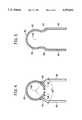
- FIGS. 3, 4 and 5are, respectively, elevational views taken in section along respective section lines 3--3, 4--4 and 5--5 in FIG. 1;
- FIG. 6is a developed plan view of a blank used to from the terminal shown in FIGS. 1 through 5;
- FIGS. 7 and 8are, respectively, an isolated perspective view and a side elevational view (in section) of a housing adapted to accept the terminal of FIGS. 1 through 6.
- the terminal 10is formed by stamping from a blank of a suitable conductive material, such a phoshorous bronze material. A developed view of the blank is illustrated in FIG. 6.
- the terminal 10includes a contact receiving portion 12 and an integral mounting portion 14.
- a reference axis 10Aextends through the terminal 10.
- the contact receiving portion 12includes a web 16 from which extend a plurality of beams, or fingers, 20.
- the beamsare preferably equiangularly arranged about the axis 10A. In the embodiment illustrated five beams 20 are shown, each beam being angularly separated from the angularly adjacent beam by a gap 20G (FIG. 2).
- each of the beams 20has a curved inside surface 20S with an inward bend 20B located axially therealong. The portion of the beams 20 forward of the bends 20B flare to define a funnel-like pin guide 24.
- the beams 20cooperate to form an axially extending tubular socket region 26.
- the socket region 26is thus adapted to surround a male pin guided therein over 360° of its periphery.
- the inner surface 20S of the beams 20 at the bends 20Bdefine a substantially continuous cylindrical contact surface 28 lying at a predetermined point 30 along the reference axis 10A within the tubular socket region 26.
- the contact surface 28is, as may be best seen in FIGS. 2 and 3, interrupted only by the gap 20G between angularly adjacent beams 20.
- the cylindrical contact surface 28 defined by the bends 20B of each beam 20defines a circle centered on the reference axis 10A of the terminal.
- the surface 28thus imparts a predetermined constricted dimension 36 (i.e., the diameter of the surface 28) measured in a plane perpendicular to the reference axis 10A.
- This dimension 36 of the substantially continuous cylindrical contact surface 28is the most constricted dimension along the reference axis 10A of the terminal.
- the through bore of the socket region 26 of the terminal 10is thus effectively unlimited.
- the terminal 10is thereby able to accommodate a pin of any desired axial length.
- two of the beams 20are provided with latch tabs 38.
- the tabs 38extend outwardly beyond the basic outer diametric dimension of the contact receiving portion 12.
- the tabs 38may be conveniently located on any of the beams 20.
- the tab(s) 38are formed as appendages disposed axially between the laterally outward beam(s) 20' and the mounting portion 14.
- the tabs 38may be additionally or alternately formed by punching through the material of the web 16.
- the trailing mounting portion 14extends rearwardly from the web 16.
- the mounting portion 14includes a hood region 40 melding into a pair of lateral flanges 42. As is best seen in FIG. 4 and 5 the hood 40 and the flanges 42 preferably extend substantially 270° about the reference axis 10A of the terminal 10.
- the flanges 42are bent outwardly, as at 44.
- a plurality of mounting legs 46 depending from each flange 42defines a set of mounting legs for the terminal 10. The mounting legs 46 each extend downwardly a substantial distance below the contact receiving portion 12.
- the mounting legs 46extend generally perpendicularly to the reference axis 10A of the terminal.
- the mounting legs 46may be received by plated through bores provided in the surface of a substrate whereby electrical interconnection may be effected between the terminal 10 and a backplane on the substrate. It should be understood that is within the contemplation of the present invention to arrange the legs 46 such that they align parallel to the reference axis 10A of the terminal. Such an arrangement is suggested in dot-dash lines in FIG. 6.
- the terminal 10is formed from the blank B shown in developed view in FIG. 6.
- the blank Bis attached to a carrier strip (not shown) by a tail T.
- the blankis made by a stamping operation and the terminal 10 is formed therefrom by bending the blank over a mandrel, as is understood by those skilled in the art.
- the terminal 10is received within a housing 50 formed from a block of a suitable insulating material.
- the housing 50has an through passage 52 therein.
- Locating guide members 54extend axially along the walls of the passage 52 to position the terminal 10 (shown in dot-dash lines in FIG. 8) within the housing.
- Locking ribs 56are disposed about the open end of the passage 52.
- the terminal 10is inserted into the passage 52 in the housing 50 in the direction of the arrow 58.
- the latches 38 on the beams 20are resiliently deflected as the terminal 10 is inserted into the housing 50. Once axially past the locking ribs 54 the latches 38 snap into locking position behind the locking ribs 56.
- the circumferential extent of the locking ribs 54is such that the tabs 38 will engage against a rib 54 to retain the terminal 10, once inserted, within the housing 50.
- a terminal 10 in accordance with the present inventionpresents no impediment to the axial advance of a male pin.
- a pin having any desired lengthmay be received coaxially with the reference axis of the terminal.
- Such a capabilityis believed advantageous when using the terminal of the present invention in a so-called "first break-last break" interconnection system.
Landscapes
- Connector Housings Or Holding Contact Members (AREA)
- Manufacturing Of Electrical Connectors (AREA)
- Multi-Conductor Connections (AREA)
- Coupling Device And Connection With Printed Circuit (AREA)
Abstract
Description
Claims (10)
Priority Applications (1)
| Application Number | Priority Date | Filing Date | Title |
|---|---|---|---|
| US08/143,538US5376012A (en) | 1992-02-12 | 1993-10-26 | Power port terminal |
Applications Claiming Priority (2)
| Application Number | Priority Date | Filing Date | Title |
|---|---|---|---|
| US84326192A | 1992-02-12 | 1992-02-12 | |
| US08/143,538US5376012A (en) | 1992-02-12 | 1993-10-26 | Power port terminal |
Related Parent Applications (1)
| Application Number | Title | Priority Date | Filing Date |
|---|---|---|---|
| US84326192AContinuation | 1992-02-12 | 1992-02-12 |
Publications (1)
| Publication Number | Publication Date |
|---|---|
| US5376012Atrue US5376012A (en) | 1994-12-27 |
Family
ID=25289479
Family Applications (1)
| Application Number | Title | Priority Date | Filing Date |
|---|---|---|---|
| US08/143,538Expired - LifetimeUS5376012A (en) | 1992-02-12 | 1993-10-26 | Power port terminal |
Country Status (5)
| Country | Link |
|---|---|
| US (1) | US5376012A (en) |
| EP (1) | EP0626104B1 (en) |
| JP (2) | JPH07506694A (en) |
| DE (1) | DE69321708T2 (en) |
| WO (1) | WO1993016509A1 (en) |
Cited By (53)
| Publication number | Priority date | Publication date | Assignee | Title |
|---|---|---|---|---|
| US5522737A (en)* | 1992-03-24 | 1996-06-04 | Molex Incorporated | Impedance and inductance control in electrical connectors and including reduced crosstalk |
| US5618187A (en)* | 1994-11-17 | 1997-04-08 | The Whitaker Corporation | Board mount bus bar contact |
| US5653616A (en)* | 1994-06-13 | 1997-08-05 | The Whitaker Corporation | Electrical receptacle terminal |
| WO1997028579A1 (en)* | 1996-02-02 | 1997-08-07 | Berg Technology, Inc. | Stamped power contact |
| US5667392A (en)* | 1995-03-28 | 1997-09-16 | The Whitaker Corporation | Electrical connector with stabilized contact |
| US5669774A (en)* | 1994-09-06 | 1997-09-23 | Grabbe; Dimitry | Ball grid array socket |
| US5713764A (en)* | 1992-03-16 | 1998-02-03 | Molex Incorporated | Impedance and inductance control in electrical connectors |
| US5807120A (en)* | 1996-03-06 | 1998-09-15 | Elcon Products International | Printed circuit board power distribution connector |
| USD408361S (en)* | 1998-04-24 | 1999-04-20 | Elcon Products International Company | Electrical connector housing |
| USD408789S (en) | 1998-04-16 | 1999-04-27 | Elcon Products International Company | Electrical connector housing |
| USD410894S (en)* | 1998-04-24 | 1999-06-15 | Elcon Products International Company | Electrical connector housing |
| USD411173S (en) | 1998-04-24 | 1999-06-22 | Elcon Products International | Electrical connector housing |
| USD412489S (en)* | 1998-04-16 | 1999-08-03 | Elcon Products International | Electrical connector housing |
| US5938487A (en)* | 1997-03-25 | 1999-08-17 | The Whitaker Corporation | Socket contact having tapered beam |
| US6015299A (en)* | 1998-07-22 | 2000-01-18 | Molex Incorporated | Card edge connector with symmetrical board contacts |
| US6095821A (en)* | 1998-07-22 | 2000-08-01 | Molex Incorporated | Card edge connector with improved reference terminals |
| US6190215B1 (en) | 1997-01-31 | 2001-02-20 | Berg Technology, Inc. | Stamped power contact |
| US6319075B1 (en) | 1998-04-17 | 2001-11-20 | Fci Americas Technology, Inc. | Power connector |
| US6461174B1 (en)* | 2001-09-12 | 2002-10-08 | Hon Hai Precision Ind. Co., Ltd. | Power connector more easily and cheaply manufactured |
| US6623277B1 (en)* | 2002-04-30 | 2003-09-23 | Hon Hai Precision Ind. Co., Ltd. | Power connector |
| FR2839586A1 (en)* | 2002-05-07 | 2003-11-14 | Pierron Ind | Electronic card socket having electrical connection having electronic card fixing connection with fixing mechanism providing electrical connection. |
| US6695644B2 (en)* | 2002-04-30 | 2004-02-24 | Hon Hai Precision Ind. Co., Ltd. | Power connector having improved contact |
| US20040147177A1 (en)* | 2003-01-27 | 2004-07-29 | Wagner Douglas L. | Power connector with male and female contacts |
| US20040147169A1 (en)* | 2003-01-28 | 2004-07-29 | Allison Jeffrey W. | Power connector with safety feature |
| US6780027B2 (en) | 2003-01-28 | 2004-08-24 | Fci Americas Technology, Inc. | Power connector with vertical male AC power contacts |
| US20040171314A1 (en)* | 2002-12-10 | 2004-09-02 | Jurgen Lappohn | Electrical plug-in connector with a housing and a high-current contact |
| US20040235357A1 (en)* | 2003-05-23 | 2004-11-25 | Allison Jeffrey W. | Multi-interface power contact and electrical connector including same |
| US6848953B2 (en) | 1998-04-17 | 2005-02-01 | Fci Americas Technology, Inc. | Power connector |
| US7001189B1 (en)* | 2004-11-04 | 2006-02-21 | Molex Incorporated | Board mounted power connector |
| US20060089058A1 (en)* | 2002-07-31 | 2006-04-27 | Horst Derleth | Method for producing a contact part |
| US20060166536A1 (en)* | 1998-04-17 | 2006-07-27 | Northey William A | Electrical power connector |
| US20060217005A1 (en)* | 2005-03-26 | 2006-09-28 | Amphenol-Tuchel Electronics Gmbh | Electrical connector jack |
| US20070147584A1 (en)* | 2005-12-27 | 2007-06-28 | Hofman Gertjan J | Measurement of ash composition using scanning high voltage X-ray sensor |
| US20080242151A1 (en)* | 2007-03-29 | 2008-10-02 | Alltop Technology Co., Ltd. | Female connector terminal for electric power connector |
| USD619099S1 (en) | 2009-01-30 | 2010-07-06 | Fci Americas Technology, Inc. | Electrical connector |
| USD665360S1 (en) | 2011-10-21 | 2012-08-14 | Fci Americas Technology Llc | Electrical terminal |
| WO2012151484A1 (en)* | 2011-05-05 | 2012-11-08 | Lear Corporation | Female type contact for an electrical connector |
| US8323049B2 (en) | 2009-01-30 | 2012-12-04 | Fci Americas Technology Llc | Electrical connector having power contacts |
| US8840436B2 (en) | 2011-05-05 | 2014-09-23 | Lear Corporation | Electrically conducting terminal |
| US8876562B2 (en) | 2011-05-05 | 2014-11-04 | Lear Corporation | Female type contact for an electrical connector |
| DE202015002712U1 (en) | 2015-04-13 | 2015-06-09 | Power2Pcb Gmbh | Mounting device for a connection element |
| US9065224B2 (en) | 2011-06-03 | 2015-06-23 | Greatbatch Ltd. | Feedthrough wire connector for use in a medical device |
| DE202015006560U1 (en) | 2015-09-15 | 2015-10-22 | Power2Pcb Gmbh | Connection element with positioning |
| US9352708B2 (en) | 2011-08-22 | 2016-05-31 | Lear Corporation | Connector assembly and terminal retainer |
| US20170133781A1 (en)* | 2015-11-10 | 2017-05-11 | Advanced-Connectek Inc. | Plug terminal |
| US9692173B2 (en) | 2011-06-03 | 2017-06-27 | Greatbatch Ltd. | Feedthrough wire connector for use in a medical device |
| EP3297098A1 (en)* | 2016-09-20 | 2018-03-21 | Harwin PLC | Electrical contact |
| US20190237888A1 (en)* | 2018-01-26 | 2019-08-01 | Tatsuta Electric Wire & Cable Co., Ltd. | Connector Terminal, Connector Including the Connector Terminal, and Method for Producing the Connector Terminal |
| US10855017B2 (en) | 2018-01-26 | 2020-12-01 | Tatsuta Electric Wire & Cable Co., Ltd. | Connector terminal, connector, and size adjustment device |
| US11211741B2 (en) | 2011-06-03 | 2021-12-28 | Greatbatch Ltd. | Removable terminal pin connector for an active electronics circuit board for use in an implantable medical device |
| US11349241B2 (en) | 2020-09-21 | 2022-05-31 | TE Connectivity Services Gmbh | Power socket for electrical connector system |
| WO2024045612A1 (en)* | 2022-08-29 | 2024-03-07 | 中航光电科技股份有限公司 | Welding-free jack used for circuit board |
| US12218458B2 (en) | 2020-03-05 | 2025-02-04 | Greatbatch Ltd. | High-voltage electrical insulation for use in active implantable medical devices circuit board connectors |
Families Citing this family (7)
| Publication number | Priority date | Publication date | Assignee | Title |
|---|---|---|---|---|
| FR2730097B1 (en)* | 1995-01-30 | 1997-04-04 | Framatome Connectors France | METHOD FOR PRODUCING A TERMINAL BOARD FOR MOUNTING ON A PRINTED CIRCUIT AND TERMINAL BOARD OBTAINED BY SUCH A METHOD |
| JP5279912B2 (en)* | 2008-09-10 | 2013-09-04 | エフシーアイ | Electrical contact, set of electrical contacts, product and assembly comprising such electrical contact, method for manufacturing the same, and electrical connection method |
| DE102008058204A1 (en)* | 2008-11-12 | 2010-05-20 | Würth Elektronik Ics Gmbh & Co. Kg | receptacle |
| JP2011113680A (en)* | 2009-11-24 | 2011-06-09 | Panasonic Electric Works Co Ltd | Screw terminal and receptacle with this |
| JP5759819B2 (en)* | 2011-07-25 | 2015-08-05 | 株式会社平川製作所 | Method for manufacturing female connection terminal of charging connector for electric vehicle |
| JP2014107079A (en)* | 2012-11-27 | 2014-06-09 | Auto Network Gijutsu Kenkyusho:Kk | Multi-contact type female terminal |
| JP5937725B2 (en)* | 2015-05-11 | 2016-06-22 | 矢崎総業株式会社 | Terminal fitting |
Citations (13)
| Publication number | Priority date | Publication date | Assignee | Title |
|---|---|---|---|---|
| US3026496A (en)* | 1957-06-05 | 1962-03-20 | Ind Electronic Hardware Corp | Electrical socket and contact therefor |
| US3083351A (en)* | 1961-04-10 | 1963-03-26 | Jr Auker J Nielsen | Electrical receptacle |
| US4002400A (en)* | 1975-08-01 | 1977-01-11 | E. I. Du Pont De Nemours And Company | Electrical connector |
| US4359258A (en)* | 1980-01-14 | 1982-11-16 | Trw Inc. | Electrical connector |
| US4582386A (en)* | 1984-11-01 | 1986-04-15 | Elfab Corp. | Connector with enlarged power contact |
| US4702707A (en)* | 1986-08-15 | 1987-10-27 | Amp Incorporated | Power contact having removable mating components |
| US4749357A (en)* | 1985-12-23 | 1988-06-07 | Elcon Products International Company | Circuit board connector, bus and system |
| US4776651A (en)* | 1985-12-06 | 1988-10-11 | Amp Incorporated | Socket contacts |
| US4790763A (en)* | 1986-04-22 | 1988-12-13 | Amp Incorporated | Programmable modular connector assembly |
| US4824380A (en)* | 1987-11-24 | 1989-04-25 | Elcon Products International Company | Quick disconnect connector and system with integral conductor |
| US4837927A (en)* | 1985-04-22 | 1989-06-13 | Savage John Jun | Method of mounting circuit component to a circuit board |
| US5055055A (en)* | 1990-10-12 | 1991-10-08 | Elcon Products International Company | Circuit board connector system |
| US5131873A (en)* | 1990-09-11 | 1992-07-21 | Molex Incorporated | Female electrical terminal |
Family Cites Families (3)
| Publication number | Priority date | Publication date | Assignee | Title |
|---|---|---|---|---|
| US2689337A (en)* | 1952-04-04 | 1954-09-14 | Burtt | Shaped metal contact |
| DE3302824A1 (en)* | 1983-01-28 | 1984-08-02 | Grote & Hartmann | ADDITIONAL LOCKING ELEMENT FOR ROUND CONNECTORS |
| IT1179895B (en)* | 1984-12-28 | 1987-09-16 | Burndy Electra Spa | FEMALE ELECTRIC CONTACT ELEMENT WITH RELATIVELY REDUCED COUPLING EFFORT AND RELATIVE CONNECTOR COMPLEX |
- 1993
- 1993-02-11EPEP93905876Apatent/EP0626104B1/ennot_activeExpired - Lifetime
- 1993-02-11WOPCT/US1993/001217patent/WO1993016509A1/enactiveIP Right Grant
- 1993-02-11JPJP5514284Apatent/JPH07506694A/enactivePending
- 1993-02-11DEDE69321708Tpatent/DE69321708T2/ennot_activeExpired - Lifetime
- 1993-10-26USUS08/143,538patent/US5376012A/ennot_activeExpired - Lifetime
- 2001
- 2001-12-17JPJP2001008199Upatent/JP2607881Y2/ennot_activeExpired - Lifetime
Patent Citations (13)
| Publication number | Priority date | Publication date | Assignee | Title |
|---|---|---|---|---|
| US3026496A (en)* | 1957-06-05 | 1962-03-20 | Ind Electronic Hardware Corp | Electrical socket and contact therefor |
| US3083351A (en)* | 1961-04-10 | 1963-03-26 | Jr Auker J Nielsen | Electrical receptacle |
| US4002400A (en)* | 1975-08-01 | 1977-01-11 | E. I. Du Pont De Nemours And Company | Electrical connector |
| US4359258A (en)* | 1980-01-14 | 1982-11-16 | Trw Inc. | Electrical connector |
| US4582386A (en)* | 1984-11-01 | 1986-04-15 | Elfab Corp. | Connector with enlarged power contact |
| US4837927A (en)* | 1985-04-22 | 1989-06-13 | Savage John Jun | Method of mounting circuit component to a circuit board |
| US4776651A (en)* | 1985-12-06 | 1988-10-11 | Amp Incorporated | Socket contacts |
| US4749357A (en)* | 1985-12-23 | 1988-06-07 | Elcon Products International Company | Circuit board connector, bus and system |
| US4790763A (en)* | 1986-04-22 | 1988-12-13 | Amp Incorporated | Programmable modular connector assembly |
| US4702707A (en)* | 1986-08-15 | 1987-10-27 | Amp Incorporated | Power contact having removable mating components |
| US4824380A (en)* | 1987-11-24 | 1989-04-25 | Elcon Products International Company | Quick disconnect connector and system with integral conductor |
| US5131873A (en)* | 1990-09-11 | 1992-07-21 | Molex Incorporated | Female electrical terminal |
| US5055055A (en)* | 1990-10-12 | 1991-10-08 | Elcon Products International Company | Circuit board connector system |
Non-Patent Citations (4)
| Title |
|---|
| Du Pont HPC Connector System Bulletin, "Meets need for reliable, high density, low insertion force interconnect systems", pp. 6, 12, 15, and 18, Jan. 1987. |
| Du Pont HPC Connector System Bulletin, Meets need for reliable, high density, low insertion force interconnect systems , pp. 6, 12, 15, and 18, Jan. 1987.* |
| Du Pont Interconnecting & Packaging Brochure, pp. 334 335, Aug. 1988.* |
| Du Pont Interconnecting & Packaging Brochure, pp. 334-335, Aug. 1988. |
Cited By (94)
| Publication number | Priority date | Publication date | Assignee | Title |
|---|---|---|---|---|
| US5713764A (en)* | 1992-03-16 | 1998-02-03 | Molex Incorporated | Impedance and inductance control in electrical connectors |
| US5522737A (en)* | 1992-03-24 | 1996-06-04 | Molex Incorporated | Impedance and inductance control in electrical connectors and including reduced crosstalk |
| US5853303A (en)* | 1992-03-24 | 1998-12-29 | Molex Incorporated | Impedance and inductance control in electrical connectors and including reduced crosstalk |
| US6019639A (en)* | 1992-03-24 | 2000-02-01 | Molex Incorporated | Impedance and inductance control in electrical connectors and including reduced crosstalk |
| US5653616A (en)* | 1994-06-13 | 1997-08-05 | The Whitaker Corporation | Electrical receptacle terminal |
| US5669774A (en)* | 1994-09-06 | 1997-09-23 | Grabbe; Dimitry | Ball grid array socket |
| US5618187A (en)* | 1994-11-17 | 1997-04-08 | The Whitaker Corporation | Board mount bus bar contact |
| US5667392A (en)* | 1995-03-28 | 1997-09-16 | The Whitaker Corporation | Electrical connector with stabilized contact |
| WO1997028579A1 (en)* | 1996-02-02 | 1997-08-07 | Berg Technology, Inc. | Stamped power contact |
| US5807120A (en)* | 1996-03-06 | 1998-09-15 | Elcon Products International | Printed circuit board power distribution connector |
| US6190215B1 (en) | 1997-01-31 | 2001-02-20 | Berg Technology, Inc. | Stamped power contact |
| US5938487A (en)* | 1997-03-25 | 1999-08-17 | The Whitaker Corporation | Socket contact having tapered beam |
| USD408789S (en) | 1998-04-16 | 1999-04-27 | Elcon Products International Company | Electrical connector housing |
| USD412489S (en)* | 1998-04-16 | 1999-08-03 | Elcon Products International | Electrical connector housing |
| US7314377B2 (en) | 1998-04-17 | 2008-01-01 | Fci Americas Technology, Inc. | Electrical power connector |
| US20080214027A1 (en)* | 1998-04-17 | 2008-09-04 | Schell Mark S | Power connector |
| US20050118846A1 (en)* | 1998-04-17 | 2005-06-02 | Berg Technologies, Inc. | Power connector |
| US7059919B2 (en) | 1998-04-17 | 2006-06-13 | Fci Americas Technology, Inc | Power connector |
| US7070464B2 (en) | 1998-04-17 | 2006-07-04 | Fci Americas Technology, Inc. | Power connector |
| US6319075B1 (en) | 1998-04-17 | 2001-11-20 | Fci Americas Technology, Inc. | Power connector |
| US20020034889A1 (en)* | 1998-04-17 | 2002-03-21 | Clark Stephen L. | Power connector |
| US6869294B2 (en) | 1998-04-17 | 2005-03-22 | Fci Americas Technology, Inc. | Power connector |
| US8096814B2 (en) | 1998-04-17 | 2012-01-17 | Fci Americas Technology Llc | Power connector |
| US7488222B2 (en) | 1998-04-17 | 2009-02-10 | Fci Americas Technology, Inc. | Power connector |
| US6848953B2 (en) | 1998-04-17 | 2005-02-01 | Fci Americas Technology, Inc. | Power connector |
| US20060166536A1 (en)* | 1998-04-17 | 2006-07-27 | Northey William A | Electrical power connector |
| US7374436B2 (en) | 1998-04-17 | 2008-05-20 | Fci Americas Technology, Inc. | Power connector |
| US20050136713A1 (en)* | 1998-04-17 | 2005-06-23 | Schell Mark S. | Power connector |
| US7309242B2 (en) | 1998-04-17 | 2007-12-18 | Fci Americas Technology, Inc. | Power connector |
| US20060194481A1 (en)* | 1998-04-17 | 2006-08-31 | Fci Americas Technology, Inc. | Power connector |
| USD408361S (en)* | 1998-04-24 | 1999-04-20 | Elcon Products International Company | Electrical connector housing |
| USD410894S (en)* | 1998-04-24 | 1999-06-15 | Elcon Products International Company | Electrical connector housing |
| USD411173S (en) | 1998-04-24 | 1999-06-22 | Elcon Products International | Electrical connector housing |
| US6015299A (en)* | 1998-07-22 | 2000-01-18 | Molex Incorporated | Card edge connector with symmetrical board contacts |
| USRE38736E1 (en) | 1998-07-22 | 2005-05-17 | Molex Incorporated | Card edge connector with symmetrical board contacts |
| US6095821A (en)* | 1998-07-22 | 2000-08-01 | Molex Incorporated | Card edge connector with improved reference terminals |
| US6461174B1 (en)* | 2001-09-12 | 2002-10-08 | Hon Hai Precision Ind. Co., Ltd. | Power connector more easily and cheaply manufactured |
| US6695644B2 (en)* | 2002-04-30 | 2004-02-24 | Hon Hai Precision Ind. Co., Ltd. | Power connector having improved contact |
| US6623277B1 (en)* | 2002-04-30 | 2003-09-23 | Hon Hai Precision Ind. Co., Ltd. | Power connector |
| FR2839586A1 (en)* | 2002-05-07 | 2003-11-14 | Pierron Ind | Electronic card socket having electrical connection having electronic card fixing connection with fixing mechanism providing electrical connection. |
| US7234236B2 (en)* | 2002-07-31 | 2007-06-26 | Susanne Derleth, legal representative | Method for producing a contact part |
| US20060089058A1 (en)* | 2002-07-31 | 2006-04-27 | Horst Derleth | Method for producing a contact part |
| US6979235B2 (en)* | 2002-12-10 | 2005-12-27 | Erni Elektroapparate Gmbh | Electrical plug-in connector with a housing and a high-current contact |
| US20040171314A1 (en)* | 2002-12-10 | 2004-09-02 | Jurgen Lappohn | Electrical plug-in connector with a housing and a high-current contact |
| US7040936B2 (en)* | 2002-12-10 | 2006-05-09 | Erni Elektroapparate Gmbh | Housing for an electrical plug-in connector |
| US20050106949A1 (en)* | 2002-12-10 | 2005-05-19 | Erni Elektroapparate Gmbh | Housing for an electrical plug-in connector |
| US20040147177A1 (en)* | 2003-01-27 | 2004-07-29 | Wagner Douglas L. | Power connector with male and female contacts |
| US6890221B2 (en) | 2003-01-27 | 2005-05-10 | Fci Americas Technology, Inc. | Power connector with male and female contacts |
| US20040147169A1 (en)* | 2003-01-28 | 2004-07-29 | Allison Jeffrey W. | Power connector with safety feature |
| USRE41283E1 (en) | 2003-01-28 | 2010-04-27 | Fci Americas Technology, Inc. | Power connector with safety feature |
| US7140925B2 (en) | 2003-01-28 | 2006-11-28 | Fci Americas Technology, Inc. | Power connector with safety feature |
| US7037142B2 (en) | 2003-01-28 | 2006-05-02 | Fci Americas Technology, Inc. | Power connector with safety feature |
| US6780027B2 (en) | 2003-01-28 | 2004-08-24 | Fci Americas Technology, Inc. | Power connector with vertical male AC power contacts |
| US20050227514A1 (en)* | 2003-01-28 | 2005-10-13 | Allison Jeffrey W | Power connector with safety feature |
| US20060063435A1 (en)* | 2003-01-28 | 2006-03-23 | Evans Robert F | Power connector with safety feature |
| US20040235357A1 (en)* | 2003-05-23 | 2004-11-25 | Allison Jeffrey W. | Multi-interface power contact and electrical connector including same |
| US6848950B2 (en) | 2003-05-23 | 2005-02-01 | Fci Americas Technology, Inc. | Multi-interface power contact and electrical connector including same |
| US7001189B1 (en)* | 2004-11-04 | 2006-02-21 | Molex Incorporated | Board mounted power connector |
| US20060217005A1 (en)* | 2005-03-26 | 2006-09-28 | Amphenol-Tuchel Electronics Gmbh | Electrical connector jack |
| US20070147584A1 (en)* | 2005-12-27 | 2007-06-28 | Hofman Gertjan J | Measurement of ash composition using scanning high voltage X-ray sensor |
| US20080242151A1 (en)* | 2007-03-29 | 2008-10-02 | Alltop Technology Co., Ltd. | Female connector terminal for electric power connector |
| US7467980B2 (en)* | 2007-03-29 | 2008-12-23 | Alltop Technology Co., Ltd. | Female connector terminal for electric power connector |
| USD619099S1 (en) | 2009-01-30 | 2010-07-06 | Fci Americas Technology, Inc. | Electrical connector |
| US8323049B2 (en) | 2009-01-30 | 2012-12-04 | Fci Americas Technology Llc | Electrical connector having power contacts |
| WO2012151484A1 (en)* | 2011-05-05 | 2012-11-08 | Lear Corporation | Female type contact for an electrical connector |
| US9325095B2 (en) | 2011-05-05 | 2016-04-26 | Lear Corporation | Female type contact for an electrical connector |
| CN103597668B (en)* | 2011-05-05 | 2017-05-24 | 李尔公司 | Female contactors for electrical connectors |
| CN103597668A (en)* | 2011-05-05 | 2014-02-19 | 李尔公司 | Female contactors for electrical connectors |
| US8840436B2 (en) | 2011-05-05 | 2014-09-23 | Lear Corporation | Electrically conducting terminal |
| US8876562B2 (en) | 2011-05-05 | 2014-11-04 | Lear Corporation | Female type contact for an electrical connector |
| US9356377B2 (en) | 2011-05-05 | 2016-05-31 | Lear Corporation | Electrically conducting terminal |
| US9065224B2 (en) | 2011-06-03 | 2015-06-23 | Greatbatch Ltd. | Feedthrough wire connector for use in a medical device |
| US10587073B2 (en) | 2011-06-03 | 2020-03-10 | Greatbatch Ltd. | Circuit board having a feedthrough wire connector for use in a medical device |
| US12272899B2 (en) | 2011-06-03 | 2025-04-08 | Greatbatch Ltd. | Common housing for a plurality of terminal pin connectors for use in an implantable medical device |
| US9692173B2 (en) | 2011-06-03 | 2017-06-27 | Greatbatch Ltd. | Feedthrough wire connector for use in a medical device |
| US12149021B2 (en) | 2011-06-03 | 2024-11-19 | Greatbatch Ltd. | Removable terminal pin connector for an active electronics circuit board for use in an implantable medical device |
| US11211741B2 (en) | 2011-06-03 | 2021-12-28 | Greatbatch Ltd. | Removable terminal pin connector for an active electronics circuit board for use in an implantable medical device |
| US9352708B2 (en) | 2011-08-22 | 2016-05-31 | Lear Corporation | Connector assembly and terminal retainer |
| US9761983B2 (en) | 2011-08-22 | 2017-09-12 | Lear Corporation | Connector assembly and terminal retainer |
| USD668621S1 (en) | 2011-10-21 | 2012-10-09 | Fci Americas Technology Llc | Electrical terminal |
| USD665360S1 (en) | 2011-10-21 | 2012-08-14 | Fci Americas Technology Llc | Electrical terminal |
| DE202015002712U1 (en) | 2015-04-13 | 2015-06-09 | Power2Pcb Gmbh | Mounting device for a connection element |
| DE202015006560U1 (en) | 2015-09-15 | 2015-10-22 | Power2Pcb Gmbh | Connection element with positioning |
| US9819109B2 (en)* | 2015-11-10 | 2017-11-14 | Advanced-Connectek Inc. | Plug terminal |
| US20170133781A1 (en)* | 2015-11-10 | 2017-05-11 | Advanced-Connectek Inc. | Plug terminal |
| US10411381B2 (en) | 2016-09-20 | 2019-09-10 | Harwin Plc | Electrical contact |
| EP3297098A1 (en)* | 2016-09-20 | 2018-03-21 | Harwin PLC | Electrical contact |
| CN110086024A (en)* | 2018-01-26 | 2019-08-02 | 拓自达电线株式会社 | The manufacturing method of bonder terminal, the connector with bonder terminal and bonder terminal |
| US20190237888A1 (en)* | 2018-01-26 | 2019-08-01 | Tatsuta Electric Wire & Cable Co., Ltd. | Connector Terminal, Connector Including the Connector Terminal, and Method for Producing the Connector Terminal |
| US10644424B2 (en)* | 2018-01-26 | 2020-05-05 | Tatsuta Electric Wire & Cable Co., Ltd. | Connector terminal, connector including the connector terminal, and method for producing the connector terminal |
| US10855017B2 (en) | 2018-01-26 | 2020-12-01 | Tatsuta Electric Wire & Cable Co., Ltd. | Connector terminal, connector, and size adjustment device |
| US12218458B2 (en) | 2020-03-05 | 2025-02-04 | Greatbatch Ltd. | High-voltage electrical insulation for use in active implantable medical devices circuit board connectors |
| US11349241B2 (en) | 2020-09-21 | 2022-05-31 | TE Connectivity Services Gmbh | Power socket for electrical connector system |
| WO2024045612A1 (en)* | 2022-08-29 | 2024-03-07 | 中航光电科技股份有限公司 | Welding-free jack used for circuit board |
Also Published As
| Publication number | Publication date |
|---|---|
| JP2607881Y2 (en) | 2003-10-20 |
| EP0626104B1 (en) | 1998-10-21 |
| JP2002000014U (en) | 2002-05-31 |
| EP0626104A1 (en) | 1994-11-30 |
| JPH07506694A (en) | 1995-07-20 |
| DE69321708D1 (en) | 1998-11-26 |
| DE69321708T2 (en) | 1999-03-18 |
| EP0626104A4 (en) | 1995-08-02 |
| WO1993016509A1 (en) | 1993-08-19 |
Similar Documents
| Publication | Publication Date | Title |
|---|---|---|
| US5376012A (en) | Power port terminal | |
| US6190215B1 (en) | Stamped power contact | |
| US4416504A (en) | Contact with dual cantilevered arms with narrowed, complimentary tip portions | |
| KR910003023B1 (en) | Connector having means for positively seating contacts | |
| US5645454A (en) | Right angle coaxial connector and method of assembling same | |
| US4412717A (en) | Coaxial connector plug | |
| US4453796A (en) | Coaxial connector plug | |
| US5704809A (en) | Coaxial electrical connector | |
| EP0294419A1 (en) | Low profile press fit connector. | |
| US5135417A (en) | Dual usage electrical/electronic pin terminal system | |
| EP0176554A1 (en) | Cylindrical socket contact capable of exerting a high contact force and which requires a low mating force | |
| KR870001866B1 (en) | Rib cage terminal | |
| US5037329A (en) | Angular connector for a shielded coaxial cable | |
| US6086419A (en) | Electrical connector assembly | |
| US5186663A (en) | Electrical female terminal | |
| US3323098A (en) | Sub-miniature coaxial connector | |
| US4221446A (en) | Electrical connector assembly | |
| JP2876146B2 (en) | Receptacle type contact | |
| US5954542A (en) | Rear shielding shell for a plug electric connector | |
| US5061207A (en) | Connector for a shielded coaxial cable | |
| US6186828B1 (en) | Electrical connector including coaxial cable management system | |
| EP0261839B1 (en) | Spring contact electrical connector assembly | |
| US6200163B1 (en) | Electrical connector including means for terminating the shield of a high speed cable | |
| EP0880805B1 (en) | Stamped power contact | |
| US6254402B1 (en) | Push pin ground |
Legal Events
| Date | Code | Title | Description |
|---|---|---|---|
| STCF | Information on status: patent grant | Free format text:PATENTED CASE | |
| AS | Assignment | Owner name:BERG TECHNOLOGY, INC., NEVADA Free format text:ASSIGNMENT OF ASSIGNORS INTEREST;ASSIGNOR:E.I. DU PONT DE NEMOURS AND COMPANY;REEL/FRAME:008376/0198 Effective date:19960924 | |
| FPAY | Fee payment | Year of fee payment:4 | |
| FPAY | Fee payment | Year of fee payment:8 | |
| AS | Assignment | Owner name:FCI AMERICAS TECHNOLOGY, INC., NEVADA Free format text:CHANGE OF NAME;ASSIGNOR:BERG TECHNOLOGY, INC.;REEL/FRAME:017537/0384 Effective date:20000808 | |
| AS | Assignment | Owner name:BANC OF AMERICA SECURITIES LIMITED, AS SECURITY AG Free format text:SECURITY AGREEMENT;ASSIGNOR:FCI AMERICAS TECHNOLOGY, INC.;REEL/FRAME:017400/0192 Effective date:20060331 | |
| FPAY | Fee payment | Year of fee payment:12 | |
| AS | Assignment | Owner name:FCI AMERICAS TECHNOLOGY, INC., NEVADA Free format text:CHANGE OF NAME;ASSIGNOR:BERG TECHNOLOGY, INC.;REEL/FRAME:026064/0565 Effective date:19990611 Owner name:FCI AMERICAS TECHNOLOGY LLC, NEVADA Free format text:CONVERSION TO LLC;ASSIGNOR:FCI AMERICAS TECHNOLOGY, INC.;REEL/FRAME:026064/0573 Effective date:20090930 | |
| AS | Assignment | Owner name:FCI AMERICAS TECHNOLOGY LLC (F/K/A FCI AMERICAS TE Free format text:RELEASE OF PATENT SECURITY INTEREST AT REEL/FRAME NO. 17400/0192;ASSIGNOR:BANC OF AMERICA SECURITIES LIMITED;REEL/FRAME:029377/0632 Effective date:20121026 |