US5375708A - Reusable hard clear package for video games - Google Patents
Reusable hard clear package for video gamesDownload PDFInfo
- Publication number
- US5375708A US5375708AUS08/232,370US23237094AUS5375708AUS 5375708 AUS5375708 AUS 5375708AUS 23237094 AUS23237094 AUS 23237094AUS 5375708 AUS5375708 AUS 5375708A
- Authority
- US
- United States
- Prior art keywords
- box
- key
- locking
- locking cover
- lip
- Prior art date
- Legal status (The legal status is an assumption and is not a legal conclusion. Google has not performed a legal analysis and makes no representation as to the accuracy of the status listed.)
- Expired - Fee Related
Links
Images


Classifications
- E—FIXED CONSTRUCTIONS
- E05—LOCKS; KEYS; WINDOW OR DOOR FITTINGS; SAFES
- E05B—LOCKS; ACCESSORIES THEREFOR; HANDCUFFS
- E05B73/00—Devices for locking portable objects against unauthorised removal; Miscellaneous locking devices
- E05B73/0017—Anti-theft devices, e.g. tags or monitors, fixed to articles, e.g. clothes, and to be removed at the check-out of shops
- E05B73/0023—Containers, boxes, cases or the like, e.g. for compact discs or video-cassettes, specially adapted therefor
- B—PERFORMING OPERATIONS; TRANSPORTING
- B65—CONVEYING; PACKING; STORING; HANDLING THIN OR FILAMENTARY MATERIAL
- B65D—CONTAINERS FOR STORAGE OR TRANSPORT OF ARTICLES OR MATERIALS, e.g. BAGS, BARRELS, BOTTLES, BOXES, CANS, CARTONS, CRATES, DRUMS, JARS, TANKS, HOPPERS, FORWARDING CONTAINERS; ACCESSORIES, CLOSURES, OR FITTINGS THEREFOR; PACKAGING ELEMENTS; PACKAGES
- B65D85/00—Containers, packaging elements or packages, specially adapted for particular articles or materials
- B65D85/54—Containers, packaging elements or packages, specially adapted for particular articles or materials for articles of special shape not otherwise provided for
- B65D85/544—Containers, packaging elements or packages, specially adapted for particular articles or materials for articles of special shape not otherwise provided for for gramophone records
- B—PERFORMING OPERATIONS; TRANSPORTING
- B65—CONVEYING; PACKING; STORING; HANDLING THIN OR FILAMENTARY MATERIAL
- B65D—CONTAINERS FOR STORAGE OR TRANSPORT OF ARTICLES OR MATERIALS, e.g. BAGS, BARRELS, BOTTLES, BOXES, CANS, CARTONS, CRATES, DRUMS, JARS, TANKS, HOPPERS, FORWARDING CONTAINERS; ACCESSORIES, CLOSURES, OR FITTINGS THEREFOR; PACKAGING ELEMENTS; PACKAGES
- B65D55/00—Accessories for container closures not otherwise provided for
- B65D55/02—Locking devices; Means for discouraging or indicating unauthorised opening or removal of closure
- Y—GENERAL TAGGING OF NEW TECHNOLOGICAL DEVELOPMENTS; GENERAL TAGGING OF CROSS-SECTIONAL TECHNOLOGIES SPANNING OVER SEVERAL SECTIONS OF THE IPC; TECHNICAL SUBJECTS COVERED BY FORMER USPC CROSS-REFERENCE ART COLLECTIONS [XRACs] AND DIGESTS
- Y02—TECHNOLOGIES OR APPLICATIONS FOR MITIGATION OR ADAPTATION AGAINST CLIMATE CHANGE
- Y02W—CLIMATE CHANGE MITIGATION TECHNOLOGIES RELATED TO WASTEWATER TREATMENT OR WASTE MANAGEMENT
- Y02W30/00—Technologies for solid waste management
- Y02W30/50—Reuse, recycling or recovery technologies
- Y02W30/80—Packaging reuse or recycling, e.g. of multilayer packaging
- Y—GENERAL TAGGING OF NEW TECHNOLOGICAL DEVELOPMENTS; GENERAL TAGGING OF CROSS-SECTIONAL TECHNOLOGIES SPANNING OVER SEVERAL SECTIONS OF THE IPC; TECHNICAL SUBJECTS COVERED BY FORMER USPC CROSS-REFERENCE ART COLLECTIONS [XRACs] AND DIGESTS
- Y10—TECHNICAL SUBJECTS COVERED BY FORMER USPC
- Y10T—TECHNICAL SUBJECTS COVERED BY FORMER US CLASSIFICATION
- Y10T292/00—Closure fasteners
- Y10T292/08—Bolts
- Y10T292/0801—Multiple
- Y10T292/0803—Sliding and swinging
- Y10T292/0805—Combined motion
- Y—GENERAL TAGGING OF NEW TECHNOLOGICAL DEVELOPMENTS; GENERAL TAGGING OF CROSS-SECTIONAL TECHNOLOGIES SPANNING OVER SEVERAL SECTIONS OF THE IPC; TECHNICAL SUBJECTS COVERED BY FORMER USPC CROSS-REFERENCE ART COLLECTIONS [XRACs] AND DIGESTS
- Y10—TECHNICAL SUBJECTS COVERED BY FORMER USPC
- Y10T—TECHNICAL SUBJECTS COVERED BY FORMER US CLASSIFICATION
- Y10T292/00—Closure fasteners
- Y10T292/08—Bolts
- Y10T292/0894—Spring arm
- Y10T292/0907—Multiple head
Definitions
- This inventionrelates generally to a security package for video games or the like. More particularly, it relates to a reusable hangable hard clear package that firmly contains videos with a locking arrangement to completely enclose a video game which prevents removal of the video game from the package without the use of the disclosed precise key means.
- anti-theft packageshave had a hinged lid and a locking mechanism or a simple locking mechanism that is easily overcome by the thief. Magnetic strips of various forms have also been applied to the products' packaging.
- merchantspresently have anti-theft packaging devices, there is a continued need for a more advanced locking means to prevent the creative opportunist from removing the product from the security device and exiting the retail store without purchasing the merchandise.
- Previous anti-theft locking deviceshave been overcome by using paper clips, credit cards, razor blades, teeth, magnets or various other small concealable objects. Magnetic strips are easily avoided as a theft preventative without detection by removing or damaging the strip, removing the product from its package, circumventing the sensing field, or deactivating the sensing strip. Further, magnetic strips are not cost effective because at the point of sale, magnetic strips are deactivated but are not removed for later use.
- Another disadvantage of the present anti-theft locking devicesis that keys presently in use do not aid in the removal of the locking device from the container.
- the present inventionovercomes these disadvantages by providing a relatively inexpensive reusable hard clear container with a locking device that can be used in conjunction with the merchandiser's present electronic anti-theft alarm activators. It also has a more advanced precise locking means which cannot be easily overcome without the precise key means. The locking device is also held in place by the key means while the container is removed from the locking device.
- Another object of the inventionis to provide a reusable lockable package that can be displayed or hung in an aesthetically pleasing arrangement without compromising the degree of theft prevention.
- Another object of the inventionis to provide a lockable container that cannot be overcome without the use of a precise key.
- Still another object of the inventionis to provide a reusable relatively inexpensive lockable package that can be used in conjunction with retailers' present electronic anti-theft alarm activators.
- a further object of the inventionis to provide a device that holds the locking cover as the box is removed.
- Yet another object of the inventionis to provide a device with a more advanced locking means that is simple, quick and convenient for authorized personnel to use.
- Another object of the inventionis to provide a lockable package that can be adjusted to firmly contain video games of varying sizes.
- a hard clear plastic boxwith an open end, a locking cover, an adjusting brace, a hook, and a key mechanism.
- the opening of the boxhas a lip with guide channels which retain and index the locking cover in proper position when being pressed on.
- the bottom of the boxhas an aperture that allows a hook to be snapped into position, providing a means to aesthetically display the box on display racks.
- the box lipalso has a plurality of slots which accept the locking cover's projections in a mating relationship.
- the locking coverhas a plurality of keyholes, a plurality of projections, and a lip that encompasses the box lip, completely enclosing the slots in the box lip.
- the locking coveralso has tabs that securely hold an insert that interacts with retailers' present electronic anti-theft alarm activators.
- the tabalso securely holds an adjusting brace, used to firmly contain various sized video games within the box.
- the keying mechanismincludes key pegs that disengage the lock cover's projections.
- the key basealso has clamping members that automatically holds, the lock cover while the box is removed and rotate away from the lock cover to allow the lock cover and key base to be separated.
- a video game or the likeWhen used, a video game or the like is placed inside the hard clear plastic box through the open end.
- the locking coveris then pressed onto the open end of the box.
- the locking cover projectionsengage into the box lip slots, locking the cover in place.
- On the inside of the locking coveris a tab for holding an insert that interacts with the retail store's electronic anti-theft alarm activators, further deterring removal of the security package from the store.
- the adjusting bracemay be engaged with the tab to reduce movement of smaller video games within the box.
- Authorized personnelmay remove the locking cover simply and efficiently by aligning the key base and the locking cover and pressing the two together.
- the key pegsdisengage the locking projections, moving the locking projections out of mated relation with the box lip slots, allowing the box to be removed.
- the key base clamping membersautomatically rotate into position, holding the lid in place while the box is removed.
- the clamping membersare then rotated away from the locking cover to allow removal of the locking cover from the key base.
- a hook of various shapesmay be snapped onto the bottom of the box, allowing the box to be hung on a display bar in an aesthetically pleasing fashion.
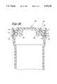
- FIG. 1is a perspective view of the anti-theft box, and locking cover, of the present invention.
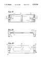
- FIG. 2is a plan view of the box, of the type shown in FIG. 1.
- FIG. 3is a partial cross-sectional view through line 3--3 of FIG. 2.
- FIG. 4is a partial cross-sectional view through line 4--4, of FIG. 2.
- FIG. 5is a partial cross-sectional view through line 5--5, broken away, of FIG. 4.
- FIG. 6is a partial cross-sectional view through line 6--6 broken away of FIG. 2.
- FIG. 7is a partial cross-sectional view through line 7--7, broken away, of FIG. 2.
- FIG. 8is a partial cross-sectional view through line 8--8, broken away, of FIG. 2.
- FIG. 9is a partial plan view of the locking cover of the type shown in FIG. 1.
- FIG. 10is a partial cross-sectional view through line 10--10 of FIG. 9.
- FIG. 11is a partial cross-sectional view through line 11--11, broken away, of FIG. 9.
- FIG. 12is a partial cross-sectional view through line 12--12, broken away, of FIG. 9.
- FIG. 13is a partial cross-sectional view through line 13--13, broken away, of FIG. 9.
- FIG. 14is an elevational end view of the locking cover shown in FIG. 9.
- FIG. 15is a bottom view of the locking cover shown in FIG. 9.
- FIG. 16is a partial sectional end view of an engaged box and locking cover, of the type shown in FIG. 1.
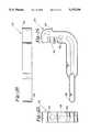
- FIG. 17is a perspective view of the key mechanism with the clamping member removed but aligned with the base and with the key insert attached to the key base.
- FIG. 18is a bottom view of the key base of the type shown in FIG. 17.
- FIG. 19is a partial sectional side elevational view of the key base of the type shown in FIG. 17.
- FIG. 20is a plan view of the key base of the type shown in FIG. 17.
- FIG. 21is a plan view of the key insert of the type shown in FIG. 17.
- FIG. 22is side elevational view of the key insert of the type shown in FIG. 17.
- FIG. 23is a partial sectional end view of the key insert of the type shown in FIG. 17.
- FIG. 24is a side elevational view of the clamping member of the type shown in FIG. 17.
- FIG. 25is a partial end view of the clamping member of the type shown in FIG. 24.
- FIG. 26is a plan view of the clamping member of the type shown in FIG. 17.
- FIG. 27is a partial sectional side elevational view, broken away, of the engaged locking cover and box with the key mechanism partially inserted.
- FIG. 28is a partial sectional side elevational view, broken away, of the engaged locking cover and box with the key mechanism inserted showing the clamping member engaged with the locking cover.
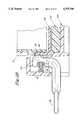
- FIG. 29is a partial sectional end view, broken away, of the engaged locking cover, box and key mechanism showing key pegs disengaging the locking cover projections from the box slot.
- FIG. 30is a side elevational view of a hook that is engaged with the box bottom of the type shown in FIG. 2.
- FIG. 31is an end elevational view of the hook of the type shown in FIG. 30.
- FIG. 32is a side elevational view of the alternate preferred embodiment of the hook of the type shown in FIG. 30.
- FIG. 33is a plan view of the hook of the type shown in FIG. 32.
- FIG. 34is an end elevational view of the hook of the type shown in FIG. 32.
- FIG. 35is a plan view of the brace that is engaged with the locking cover of the type shown in FIG. 9.
- FIG. 36is an end elevational view of the brace of the type shown in FIG. 35.
- FIG. 37is a side elevational view of the brace of the type shown in FIG. 35.
- the rectangular box 10has an open end 32 where the video game or the like is placed inside.
- the open endis formed by box lip 12 and bottom engaging edge 18 which engages with the locking cover 50 (See FIGS. 1 and 2).
- Extending on either end of the box 10are ribs 16 which extend along the length of the box providing support and rigidity (See FIGS. 1 & 4).
- Recessed in the box lips outside surface 21 on the end of box lip 12 perpendicular to bottom engaging edge 18are first guide channels 30 which locate and guide the locking cover, ensuring that even force is applied to each locking projection 58 (See FIGS. 4 and 7).
- a plurality of slots 34are formed through the side of the lip 12 parallel to the bottom engaging edge 18 (See FIGS. 3, 4, and 5). These slots serve to receive and engage with the projections 58 on the locking cover 50 (See FIG. 16).
- Recessed in the box lip 12's inner surface 20is a plurality of second guide channels 36 which are centered above each slot 34 and extend perpendicularly upward to the outer edge of the lip's inner surface 20 (See FIGS. 1, 3, 4 and 5). The second guide channels 36 serve to index and retain the key pegs 104.
- the bottom of box 38has an aperture 22 which is centered in the box bottom 38.
- the bottom of box 38also has a plurality of elongated apertures 24 symmetrically positioned an equal distance away from the center of the box (see FIGS. 1 & 2).
- a hook 160may be aligned and snapped into the aperture 22.
- the elongated aperture 24provides a second means to remove objects placed within box 10, the first means being a gravitational force provided by tipping the box, and the second means being projecting an object through aperture 24 and applying a force with the object against the video game.
- the boxis made of polycarbonate.
- Other suitable materialscan, of course, be used without deviating from the invention.
- the hook 160 shown in FIGS. 30 & 31has a concentric base 166 and a curved member 174 extending perpendicularly from the center of the base.
- a plurality of arcuate, resilient fingers 168extend perpendicularly from the center of the base 166 in a direction opposite the curved member 174.
- two arcuate, resilient fingers 168 with a tapered back 176form a semicircle and are aligned and offset opposite each other such that a tapered slot 172 is formed therebetween.
- the diameter formed by the two arcuate fingers 168is slightly less than the box bottom aperture 22.
- the tapered slot 172extends into the base 166 and curved member 174 providing further relief and resilience to the fingers 168.
- the curved member 174 extending from the center of the base 166may be of varying sizes and shapes.
- An alternative preferred embodimentis shown in FIG. 32, 33, and 34. The alternate preferred embodiment has an alternate varying size and shape of the curved member 174.
- the locking cover mechanism 50 shown in FIG. 9has a plurality of locking projections 58 having a fixed end extending perpendicularly away from the lock cover (See FIGS. 11, 12, and 13).
- a lip 86 extending perpendicularly around the perimeter of locking cover 50has an inside surface 78 which slidably engages with the outside surface of the box lip 21 (See FIGS. 12 and 16).
- a notch 52is formed on each end of the cover's lip 86 to receive a clamping member 136 (See FIGS. 10, 14, 15, 27, and 28).
- a shoulder 54extends inward on each end of the cover's lip (See FIG. 15) to slide along the first guide channel 30 indexing and retaining the locking cover 50.
- a precise keyhole 56extends through the locking cover 50 positioned above the vertical center line of the locking projection 58 (See FIGS. 9, 11, and 16).
- the locking cover 50also has a plurality of ejector pin bosses 80 that provide support to the locking cover during the molding process and further aligns the locking cover 50 with the box lip 12. (see FIG. 15, 16, and 29)
- the inside locking cover surface 90has two tab means 84 extending perpendicularly outward from it.
- the tab means 84are arranged on the inside lock cover surface 90 to accept and hold an insert that interacts with store's electronic anti-theft alarm activators (See FIGS. 10 & 15).
- Each tab 84has a slot 85 which is designed to accept and hold a brace 150.
- the adjusting brace 150has a thickness about equal to the slot 85's width, allowing the brace 150 to be firmly pressed into position (see FIGS. 35-37).
- the adjusting brace 150may be made of varying heights so that when engaged with the tabs 84, the brace 150 firmly contains various sized video games or the like within the box.
- the locking cover lip bottom edge 92engages against the box lip's bottom engaging edge 18 when the lock cover 50 is pressed onto the box lip 12 (See FIG. 16).
- the locking coveris made of polycarbonate.
- Other suitable materialscan, of course, be used without deviating from the invention.
- the key mechanism 99 shown in FIG. 17has a key base 100, a key insert 102 and a clamping member 136.
- the key base 100has a key insert 102 (see FIGS. 17 & 29) secured with a plurality of flat head screws 120 that self-tap through a plurality of key insert bores 108 and through a plurality of key base bores 110, aligning the key insert 102 with the key base 100.
- the bottom of key base 124has a rib 112 angularly extending to the key bottom inner side 123 to provide rigidity and support.
- the key base 100has sides 121 extending perpendicular to the key base 100 whose inner side 122 are slightly greater than the locking cover lip 86.
- the key insert 102has a plurality of key pegs 104 which mate with the locking cover keyholes 56 in the locking cover 50.
- the key pegs 104have sloping angles that help reduce friction between the key pegs 104 and the locking cover projections 58 when the key pegs 104 are pressed into the locking cover keyholes 56.
- the key insertis made of aluminum. Other suitable materials can, of course, be used without deviating from the invention. (see FIGS. 21, 22, 23, and 29)
- the key base sides 121have slots 114 on the inside surface of key base 122 for clamping members 136 to rotate through the base side. Slots 118 on the outside of the key base sides 125 allow the clamping member release end 138 to rotate through the key base side 121.
- a key base bore 116extends through the key base sides perpendicular to the slots 118 and 114 that accepts a rotation pin 134 that creates a rotation access for the clamping member 136. (see FIGS. 17, 18, and 19)
- the clamping member 136has a bore 128 that aligns with the key base bore 116 allowing the rotation pin 134 to be positioned through both bores.
- the clamping member 136also has a clamping member flange 126.
- the clamping member flange 126extends from the clamping member and mates with the locking cover receiving notch 52 when the key base 100 is positioned properly against the lock cover 50.
- On the side of the clamping member 136 opposite the clamping member flange 126is a clamping member spring support pillar 132, extending perpendicularly from the clamping member side in the opposite direction from the clamping flange 126.
- a spring 130 with an inner diameter slightly greater than the outside diameter of the spring support pillar 132is positioned with the spring support pillar 132 extending partially through the spring 130, retaining the spring 130.
- the clamping member spring 130provides a force against the clamping member 136, automatically rotating the clamping member 136, and engaging the clamping member flange 126 with the locking cover receiving notch 52.
- the clamping member 136also has a clamping member release end 138. A force against the clamping member release ends 138, in a direction opposite the locking cover, compresses the clamping member spring 130, causing the clamping members 136 to rotate away from the locking cover 50, releasing the clamping member flange 126 from the locking cover receiving notches 52.
- the clamping memberis made of LexonR-glass filled. Other suitable materials can, of course, be used without deviating from the invention.
- the operatorplaces a video game through the open end 32 of the box 10 until the game is completely through the open end of the box.
- the operatorthen aligns the locking cover shoulder 54 with the box's guide channel 30.
- the operatorapplies a force against the to locking cover perpendicular to the outside locking cover surface 88 engaging the bottom engaging edge 18 to the locking cover lip bottom edge 92.
- the locking cover projections 58mate with the box slots 34, locking the cover to the box. (see FIG. 16)
- the key base 100is aligned with the locking cover so that the clamping member flanges 126 are aligned with the locking cover receiving notches 52.
- the operatorthen presses the key base 100 and the box 10 together.
- the plurality of pegs 104enter through the plurality of keyholes 56 disengaging the locking cover projections 58 from the slots 34.
- the clamping member flange 126automatically engages with the locking cover receiving notches 52 allowing the operator to remove the box from the locking cover while the locking cover remains engaged with the key base 100.
- the operatorapplies a force to the clamping member release ends 138 in a direction opposite the locking cover 50.
- the forcerotates the clamping member flanges 126 away from the locking cover receiving notch 52 allowing the locking cover 50 and key base 100 to be pulled apart.
Landscapes
- Engineering & Computer Science (AREA)
- Mechanical Engineering (AREA)
- Multimedia (AREA)
- Closures For Containers (AREA)
- Packaging Of Annular Or Rod-Shaped Articles, Wearing Apparel, Cassettes, Or The Like (AREA)
Abstract
Description
Claims (16)
Priority Applications (4)
| Application Number | Priority Date | Filing Date | Title |
|---|---|---|---|
| US08/232,370US5375708A (en) | 1994-04-25 | 1994-04-25 | Reusable hard clear package for video games |
| EP19940305381EP0679784A1 (en) | 1994-04-25 | 1994-07-21 | Reusable hard clear package for video games |
| JP26743594AJPH07291336A (en) | 1994-04-25 | 1994-10-31 | Safe container and its unlocking device |
| KR1019940028929AKR950029148A (en) | 1994-04-25 | 1994-11-04 | Hard clear package for reusable video game consoles |
Applications Claiming Priority (1)
| Application Number | Priority Date | Filing Date | Title |
|---|---|---|---|
| US08/232,370US5375708A (en) | 1994-04-25 | 1994-04-25 | Reusable hard clear package for video games |
Publications (1)
| Publication Number | Publication Date |
|---|---|
| US5375708Atrue US5375708A (en) | 1994-12-27 |
Family
ID=22872829
Family Applications (1)
| Application Number | Title | Priority Date | Filing Date |
|---|---|---|---|
| US08/232,370Expired - Fee RelatedUS5375708A (en) | 1994-04-25 | 1994-04-25 | Reusable hard clear package for video games |
Country Status (4)
| Country | Link |
|---|---|
| US (1) | US5375708A (en) |
| EP (1) | EP0679784A1 (en) |
| JP (1) | JPH07291336A (en) |
| KR (1) | KR950029148A (en) |
Cited By (29)
| Publication number | Priority date | Publication date | Assignee | Title |
|---|---|---|---|---|
| US5601188A (en)* | 1996-04-18 | 1997-02-11 | Emplast, Inc. | Security package with internal pocket for a surveillance tag |
| FR2757145A1 (en)* | 1996-12-13 | 1998-06-19 | Lefebure | Machine for opening magnetic badge casings |
| GB2323835A (en)* | 1997-04-04 | 1998-10-07 | Advanced Marketing Technologie | Telescopic security container and closure releasing device. |
| US5956981A (en)* | 1997-02-18 | 1999-09-28 | Alpha Enterprises, Inc. | Universal opener |
| US6082156A (en)* | 1997-10-16 | 2000-07-04 | Jee Tae Kim | Antitheft case for preventing packed compact discs from being stolen |
| KR100290289B1 (en)* | 1999-02-22 | 2001-05-15 | 김지태 | Locking Plate Release Apparatus Of Tape Case |
| EP1099818A1 (en)* | 1999-11-13 | 2001-05-16 | Gerhard Ritter | Case for a contactless readable card |
| US6240750B1 (en) | 1999-07-15 | 2001-06-05 | Geoffrey Inc. | Security case |
| WO2001079636A1 (en)* | 2000-04-13 | 2001-10-25 | Alpha Security Products, Inc. | Security sleeve for recorded media storage containers |
| USD452247S1 (en) | 2000-09-29 | 2001-12-18 | Frank B Flynn | Game pad cover |
| WO2002007152A3 (en)* | 2000-07-18 | 2002-08-15 | Nexpak Corp | Lockable media storage box with lock and key |
| US6516639B1 (en)* | 1998-09-22 | 2003-02-11 | Carling Point Limited | Storage case |
| USD477767S1 (en) | 1998-01-29 | 2003-07-29 | Nexpak Corporation | Lock for lockable media storage container |
| US6601702B2 (en)* | 1998-01-29 | 2003-08-05 | Nexpak Corporation | Lockable media storage box with lock and key |
| US20030196917A1 (en)* | 2002-04-19 | 2003-10-23 | Broadhead Robert Malcolm | Lockable container |
| US6641483B1 (en)* | 1999-08-17 | 2003-11-04 | Sierra Design Group | Lockable security cabinet for casino game controllers |
| USD491009S1 (en) | 1998-01-29 | 2004-06-08 | Nexpak Corporation | Lockable media storage container |
| US6932341B1 (en) | 2004-02-23 | 2005-08-23 | Kenneth G. Kenyon | Video game system auxiliary cover system |
| US6955379B1 (en)* | 2001-02-23 | 2005-10-18 | Palm, Inc. | Torsional multi-axis constraining latching system |
| US7108606B1 (en) | 1999-08-17 | 2006-09-19 | Sierra Design Group | Lockable security cabinet for casino game controllers |
| US7175026B2 (en) | 2002-05-03 | 2007-02-13 | Maxtor Corporation | Memory disk shipping container with improved contaminant control |
| US20070095838A1 (en)* | 2005-05-13 | 2007-05-03 | Peter Roesler | Container with snap-in closure |
| US20080277368A1 (en)* | 2007-05-11 | 2008-11-13 | Alcan Global Pharmaceutical Packaging Inc. | Push-Squeeze-Lift Child-Resistant Closure And Container System |
| USD580854S1 (en)* | 2007-01-26 | 2008-11-18 | Samsung Electronics Co., Ltd. | Case for charger of mobile phone |
| US7552822B2 (en) | 1998-01-29 | 2009-06-30 | Nexpak Corporation | Lockable media storage box with lock and key |
| USD604737S1 (en)* | 2008-03-03 | 2009-11-24 | Blue Lounge Design, Llc | Extended desk organizer for notebook computers |
| ITMI20130332A1 (en)* | 2013-03-06 | 2014-09-07 | Federico Lastrucci | ANTI-TAGGING CONTAINER WITH VARIABLE VOLUME. |
| US20190174977A1 (en)* | 2017-12-08 | 2019-06-13 | Jason J. Beeber | Toilet bowl brush container system and method of use |
| US11885155B2 (en)* | 2011-09-29 | 2024-01-30 | Invue Security Products, Inc. | Cabinet lock for use with programmable electronic key |
Families Citing this family (5)
| Publication number | Priority date | Publication date | Assignee | Title |
|---|---|---|---|---|
| JP2741361B2 (en)* | 1995-11-10 | 1998-04-15 | 株式会社サンエイ | Videotape storage case |
| JP2784338B2 (en)* | 1995-12-28 | 1998-08-06 | 株式会社ハゴロモ | Storage container such as CD |
| US7257971B2 (en) | 2000-07-31 | 2007-08-21 | Autronics Plastics Inc. | Case with internal lock |
| WO2004088071A2 (en) | 2003-03-26 | 2004-10-14 | Autronic Plastics, Inc. | Benefit denial systems for securing an asset within a container and methods of use |
| USD544743S1 (en) | 2005-09-26 | 2007-06-19 | Autronic Plastics, Inc. | Media storage case |
Citations (18)
| Publication number | Priority date | Publication date | Assignee | Title |
|---|---|---|---|---|
| US3825143A (en)* | 1972-11-08 | 1974-07-23 | Sunbeam Plastics Corp | Childproof medicine vial |
| US3828922A (en)* | 1972-07-31 | 1974-08-13 | Marsh J Inc | Anti-theft packaging device |
| US3933240A (en)* | 1974-10-15 | 1976-01-20 | Sensormatic Electronics Corporation | Anti-theft security container |
| US4047410A (en)* | 1975-03-31 | 1977-09-13 | Mrs. Lawrence Israel | Mechanism for releasing device attaching an anti-theft monitor to merchandise |
| US4285429A (en)* | 1980-02-04 | 1981-08-25 | Mactavish William D | Tape cassette security container |
| US4589549A (en)* | 1984-03-19 | 1986-05-20 | Alpha Enterprises, Inc. | Audio cassette package |
| US4616861A (en)* | 1984-07-23 | 1986-10-14 | Nifco, Inc. | Lock device |
| US4670950A (en)* | 1985-05-13 | 1987-06-09 | Monarch Marking Systems, Inc. | Theft-deterrent tag |
| US4682688A (en)* | 1985-01-24 | 1987-07-28 | Firma Georg Knoblauch | Secured container and locking device for same |
| US4716745A (en)* | 1986-08-21 | 1988-01-05 | Alpha Enterprises, Inc. | Video cassette security device |
| US4804082A (en)* | 1987-04-08 | 1989-02-14 | Buckhorn, Inc. | Security box having sliding closure |
| US4834238A (en)* | 1987-11-06 | 1989-05-30 | Alpha Enterprises, Inc. | Cassette security package |
| US4871065A (en)* | 1988-08-19 | 1989-10-03 | Alpha Enterprises, Inc. | Compact disc security package |
| US4966020A (en)* | 1989-06-06 | 1990-10-30 | 880335 Ontario Inc. | Locking mechanism |
| US4972690A (en)* | 1990-02-14 | 1990-11-27 | Sullivan Daniel J O | Locking cassette case |
| US5039982A (en)* | 1989-05-30 | 1991-08-13 | Patago Ag | Safeguarding against burglary |
| US5050762A (en)* | 1990-03-30 | 1991-09-24 | Dusaline Giorgi | Trash container |
| US5129244A (en)* | 1991-03-11 | 1992-07-14 | Empak, Inc. | Opener for security package with rotatable locking channel |
Family Cites Families (1)
| Publication number | Priority date | Publication date | Assignee | Title |
|---|---|---|---|---|
| GB9102085D0 (en)* | 1991-01-31 | 1991-03-13 | Wright John | Security container system |
- 1994
- 1994-04-25USUS08/232,370patent/US5375708A/ennot_activeExpired - Fee Related
- 1994-07-21EPEP19940305381patent/EP0679784A1/ennot_activeWithdrawn
- 1994-10-31JPJP26743594Apatent/JPH07291336A/enactivePending
- 1994-11-04KRKR1019940028929Apatent/KR950029148A/ennot_activeWithdrawn
Patent Citations (19)
| Publication number | Priority date | Publication date | Assignee | Title |
|---|---|---|---|---|
| US3828922A (en)* | 1972-07-31 | 1974-08-13 | Marsh J Inc | Anti-theft packaging device |
| US3825143A (en)* | 1972-11-08 | 1974-07-23 | Sunbeam Plastics Corp | Childproof medicine vial |
| US3933240A (en)* | 1974-10-15 | 1976-01-20 | Sensormatic Electronics Corporation | Anti-theft security container |
| US4047410A (en)* | 1975-03-31 | 1977-09-13 | Mrs. Lawrence Israel | Mechanism for releasing device attaching an anti-theft monitor to merchandise |
| US4285429A (en)* | 1980-02-04 | 1981-08-25 | Mactavish William D | Tape cassette security container |
| US4589549A (en)* | 1984-03-19 | 1986-05-20 | Alpha Enterprises, Inc. | Audio cassette package |
| US4589549B1 (en)* | 1984-03-19 | 1994-07-12 | Alpha Enterprises Inc | Audio cassette package |
| US4616861A (en)* | 1984-07-23 | 1986-10-14 | Nifco, Inc. | Lock device |
| US4682688A (en)* | 1985-01-24 | 1987-07-28 | Firma Georg Knoblauch | Secured container and locking device for same |
| US4670950A (en)* | 1985-05-13 | 1987-06-09 | Monarch Marking Systems, Inc. | Theft-deterrent tag |
| US4716745A (en)* | 1986-08-21 | 1988-01-05 | Alpha Enterprises, Inc. | Video cassette security device |
| US4804082A (en)* | 1987-04-08 | 1989-02-14 | Buckhorn, Inc. | Security box having sliding closure |
| US4834238A (en)* | 1987-11-06 | 1989-05-30 | Alpha Enterprises, Inc. | Cassette security package |
| US4871065A (en)* | 1988-08-19 | 1989-10-03 | Alpha Enterprises, Inc. | Compact disc security package |
| US5039982A (en)* | 1989-05-30 | 1991-08-13 | Patago Ag | Safeguarding against burglary |
| US4966020A (en)* | 1989-06-06 | 1990-10-30 | 880335 Ontario Inc. | Locking mechanism |
| US4972690A (en)* | 1990-02-14 | 1990-11-27 | Sullivan Daniel J O | Locking cassette case |
| US5050762A (en)* | 1990-03-30 | 1991-09-24 | Dusaline Giorgi | Trash container |
| US5129244A (en)* | 1991-03-11 | 1992-07-14 | Empak, Inc. | Opener for security package with rotatable locking channel |
Cited By (36)
| Publication number | Priority date | Publication date | Assignee | Title |
|---|---|---|---|---|
| US5601188A (en)* | 1996-04-18 | 1997-02-11 | Emplast, Inc. | Security package with internal pocket for a surveillance tag |
| FR2757145A1 (en)* | 1996-12-13 | 1998-06-19 | Lefebure | Machine for opening magnetic badge casings |
| US5956981A (en)* | 1997-02-18 | 1999-09-28 | Alpha Enterprises, Inc. | Universal opener |
| GB2323835A (en)* | 1997-04-04 | 1998-10-07 | Advanced Marketing Technologie | Telescopic security container and closure releasing device. |
| US6082156A (en)* | 1997-10-16 | 2000-07-04 | Jee Tae Kim | Antitheft case for preventing packed compact discs from being stolen |
| US6598742B1 (en) | 1998-01-29 | 2003-07-29 | Nexpak Corporation | Lockable media storage box with lock and key |
| US7552822B2 (en) | 1998-01-29 | 2009-06-30 | Nexpak Corporation | Lockable media storage box with lock and key |
| USD491009S1 (en) | 1998-01-29 | 2004-06-08 | Nexpak Corporation | Lockable media storage container |
| USD477983S1 (en) | 1998-01-29 | 2003-08-05 | Nexpak Corporation | Lock for lockable media storage container |
| US6601701B1 (en) | 1998-01-29 | 2003-08-05 | Nexpak Corporation | Lockable media storage box with lock and key |
| US6601702B2 (en)* | 1998-01-29 | 2003-08-05 | Nexpak Corporation | Lockable media storage box with lock and key |
| USD477767S1 (en) | 1998-01-29 | 2003-07-29 | Nexpak Corporation | Lock for lockable media storage container |
| US6516639B1 (en)* | 1998-09-22 | 2003-02-11 | Carling Point Limited | Storage case |
| KR100290289B1 (en)* | 1999-02-22 | 2001-05-15 | 김지태 | Locking Plate Release Apparatus Of Tape Case |
| USD449161S1 (en) | 1999-07-15 | 2001-10-16 | Geoffrey, Inc. | Security case |
| US6240750B1 (en) | 1999-07-15 | 2001-06-05 | Geoffrey Inc. | Security case |
| US6641483B1 (en)* | 1999-08-17 | 2003-11-04 | Sierra Design Group | Lockable security cabinet for casino game controllers |
| US7108606B1 (en) | 1999-08-17 | 2006-09-19 | Sierra Design Group | Lockable security cabinet for casino game controllers |
| EP1099818A1 (en)* | 1999-11-13 | 2001-05-16 | Gerhard Ritter | Case for a contactless readable card |
| WO2001079636A1 (en)* | 2000-04-13 | 2001-10-25 | Alpha Security Products, Inc. | Security sleeve for recorded media storage containers |
| WO2002007152A3 (en)* | 2000-07-18 | 2002-08-15 | Nexpak Corp | Lockable media storage box with lock and key |
| USD452247S1 (en) | 2000-09-29 | 2001-12-18 | Frank B Flynn | Game pad cover |
| US7427088B1 (en) | 2001-02-23 | 2008-09-23 | Palm, Inc. | Torsional multi-axis constraining latching system |
| US6955379B1 (en)* | 2001-02-23 | 2005-10-18 | Palm, Inc. | Torsional multi-axis constraining latching system |
| US20030196917A1 (en)* | 2002-04-19 | 2003-10-23 | Broadhead Robert Malcolm | Lockable container |
| US7175026B2 (en) | 2002-05-03 | 2007-02-13 | Maxtor Corporation | Memory disk shipping container with improved contaminant control |
| US6932341B1 (en) | 2004-02-23 | 2005-08-23 | Kenneth G. Kenyon | Video game system auxiliary cover system |
| US20070095838A1 (en)* | 2005-05-13 | 2007-05-03 | Peter Roesler | Container with snap-in closure |
| US7681755B2 (en)* | 2005-05-13 | 2010-03-23 | Peter Roesler | Container with snap-in closure |
| USD580854S1 (en)* | 2007-01-26 | 2008-11-18 | Samsung Electronics Co., Ltd. | Case for charger of mobile phone |
| US20080277368A1 (en)* | 2007-05-11 | 2008-11-13 | Alcan Global Pharmaceutical Packaging Inc. | Push-Squeeze-Lift Child-Resistant Closure And Container System |
| USD604737S1 (en)* | 2008-03-03 | 2009-11-24 | Blue Lounge Design, Llc | Extended desk organizer for notebook computers |
| US11885155B2 (en)* | 2011-09-29 | 2024-01-30 | Invue Security Products, Inc. | Cabinet lock for use with programmable electronic key |
| ITMI20130332A1 (en)* | 2013-03-06 | 2014-09-07 | Federico Lastrucci | ANTI-TAGGING CONTAINER WITH VARIABLE VOLUME. |
| EP2775074A1 (en)* | 2013-03-06 | 2014-09-10 | Federico Lastrucci | Anti-theft container of changeable volume |
| US20190174977A1 (en)* | 2017-12-08 | 2019-06-13 | Jason J. Beeber | Toilet bowl brush container system and method of use |
Also Published As
| Publication number | Publication date |
|---|---|
| KR950029148A (en) | 1995-11-22 |
| EP0679784A1 (en) | 1995-11-02 |
| JPH07291336A (en) | 1995-11-07 |
Similar Documents
| Publication | Publication Date | Title |
|---|---|---|
| US5375708A (en) | Reusable hard clear package for video games | |
| US7581419B2 (en) | Method of using lockable storage container | |
| US5509528A (en) | Display package | |
| US4381836A (en) | Anti-theft point-of-sale container | |
| US4865190A (en) | Security package with rotatable locking channel | |
| US4759442A (en) | Security package | |
| US5944185A (en) | Lockable media storage box with lock and key | |
| US6516639B1 (en) | Storage case | |
| US3871516A (en) | Antitheft packaging device | |
| EP0862677B1 (en) | Universal wrap security device | |
| US5211283A (en) | Compact disc security package with orienting tabs | |
| US4966020A (en) | Locking mechanism | |
| US7404484B2 (en) | Security device for information storage media | |
| US5417319A (en) | Security container for display of audio and video media | |
| US6637589B2 (en) | Lockable box | |
| US6926164B1 (en) | Lockable container for prerecorded storage media | |
| US20040020812A1 (en) | Lockable media storage box with lock and key | |
| US20040084344A1 (en) | Lockable media storage box with lock and key | |
| US20030116455A1 (en) | Lockable media storage container | |
| US4245741A (en) | Anti-theft packaging device | |
| EP0483422A1 (en) | Locking mechanism, particularly for anti-theft device for compact disc cassettes, video cassettes or the like | |
| JP2759060B2 (en) | Product theft prevention equipment | |
| US4714161A (en) | Security cassette holder | |
| GB2369348A (en) | Security Device for Information Storage Media | |
| US20030000853A1 (en) | Lockable box |
Legal Events
| Date | Code | Title | Description |
|---|---|---|---|
| AS | Assignment | Owner name:EMPAK, INC., MINNESOTA Free format text:ASSIGNMENT OF ASSIGNORS INTEREST;ASSIGNOR:WITTMAN, BOYD;REEL/FRAME:006978/0130 Effective date:19940415 | |
| AS | Assignment | Owner name:EMPLAST, INC., MINNESOTA Free format text:ASSIGNMENT OF ASSIGNORS INTEREST;ASSIGNOR:EMPAK, INC.;REEL/FRAME:007881/0167 Effective date:19960315 | |
| FEPP | Fee payment procedure | Free format text:PAYOR NUMBER ASSIGNED (ORIGINAL EVENT CODE: ASPN); ENTITY STATUS OF PATENT OWNER: SMALL ENTITY | |
| FPAY | Fee payment | Year of fee payment:4 | |
| FEPP | Fee payment procedure | Free format text:PAT HOLDER CLAIMS SMALL ENTITY STATUS, ENTITY STATUS SET TO SMALL (ORIGINAL EVENT CODE: LTOS); ENTITY STATUS OF PATENT OWNER: SMALL ENTITY | |
| FPAY | Fee payment | Year of fee payment:8 | |
| AS | Assignment | Owner name:MAG, INC., INDIANA Free format text:ASSIGNMENT OF ASSIGNORS INTEREST;ASSIGNOR:EMPLAST, INC.;REEL/FRAME:015612/0745 Effective date:20041231 Owner name:EMPLAST, INC., MINNESOTA Free format text:SECURITY AGREEMENT;ASSIGNOR:MAG, INC.;REEL/FRAME:015612/0752 Effective date:20041231 Owner name:COMERICA BANK, MICHIGAN Free format text:INTELLECTUAL PROPERTY SECURITY AGREEMENT;ASSIGNOR:MAG, INC.;REEL/FRAME:015612/0764 Effective date:20041231 | |
| AS | Assignment | Owner name:COMERICA BANK, MICHIGAN Free format text:NOTICE OF PRIORITY INTEREST AND PROPER ORDER OF RECORDATION OF DOCUMENTS;ASSIGNOR:MAG, INC.;REEL/FRAME:015851/0696 Effective date:20050316 | |
| AS | Assignment | Owner name:ROYNAT BUSINESS CAPITAL INC., NORTH CAROLINA Free format text:INTELLECTUAL PROPERTY SECURITY AGREEMENT;ASSIGNOR:MAG, INC.;REEL/FRAME:015908/0507 Effective date:20050318 | |
| REMI | Maintenance fee reminder mailed | ||
| LAPS | Lapse for failure to pay maintenance fees | ||
| STCH | Information on status: patent discontinuation | Free format text:PATENT EXPIRED DUE TO NONPAYMENT OF MAINTENANCE FEES UNDER 37 CFR 1.362 | |
| FP | Lapsed due to failure to pay maintenance fee | Effective date:20061227 |