US5375683A - Controllable vibration damper for motor vehicles - Google Patents
Controllable vibration damper for motor vehiclesDownload PDFInfo
- Publication number
- US5375683A US5375683AUS08/164,418US16441893AUS5375683AUS 5375683 AUS5375683 AUS 5375683AUS 16441893 AUS16441893 AUS 16441893AUS 5375683 AUS5375683 AUS 5375683A
- Authority
- US
- United States
- Prior art keywords
- valves
- fluid
- pressure
- sensitive
- attenuating
- Prior art date
- Legal status (The legal status is an assumption and is not a legal conclusion. Google has not performed a legal analysis and makes no representation as to the accuracy of the status listed.)
- Expired - Lifetime
Links
Images


Classifications
- F—MECHANICAL ENGINEERING; LIGHTING; HEATING; WEAPONS; BLASTING
- F16—ENGINEERING ELEMENTS AND UNITS; GENERAL MEASURES FOR PRODUCING AND MAINTAINING EFFECTIVE FUNCTIONING OF MACHINES OR INSTALLATIONS; THERMAL INSULATION IN GENERAL
- F16F—SPRINGS; SHOCK-ABSORBERS; MEANS FOR DAMPING VIBRATION
- F16F9/00—Springs, vibration-dampers, shock-absorbers, or similarly-constructed movement-dampers using a fluid or the equivalent as damping medium
- F16F9/06—Springs, vibration-dampers, shock-absorbers, or similarly-constructed movement-dampers using a fluid or the equivalent as damping medium using both gas and liquid
- F16F9/08—Springs, vibration-dampers, shock-absorbers, or similarly-constructed movement-dampers using a fluid or the equivalent as damping medium using both gas and liquid where gas is in a chamber with a flexible wall
- F16F9/096—Springs, vibration-dampers, shock-absorbers, or similarly-constructed movement-dampers using a fluid or the equivalent as damping medium using both gas and liquid where gas is in a chamber with a flexible wall comprising a hydropneumatic accumulator of the membrane type provided on the upper or the lower end of a damper or separately from or laterally on the damper
- F—MECHANICAL ENGINEERING; LIGHTING; HEATING; WEAPONS; BLASTING
- F16—ENGINEERING ELEMENTS AND UNITS; GENERAL MEASURES FOR PRODUCING AND MAINTAINING EFFECTIVE FUNCTIONING OF MACHINES OR INSTALLATIONS; THERMAL INSULATION IN GENERAL
- F16F—SPRINGS; SHOCK-ABSORBERS; MEANS FOR DAMPING VIBRATION
- F16F9/00—Springs, vibration-dampers, shock-absorbers, or similarly-constructed movement-dampers using a fluid or the equivalent as damping medium
- F16F9/32—Details
- F16F9/44—Means on or in the damper for manual or non-automatic adjustment; such means combined with temperature correction
- F16F9/46—Means on or in the damper for manual or non-automatic adjustment; such means combined with temperature correction allowing control from a distance, i.e. location of means for control input being remote from site of valves, e.g. on damper external wall
- B—PERFORMING OPERATIONS; TRANSPORTING
- B60—VEHICLES IN GENERAL
- B60G—VEHICLE SUSPENSION ARRANGEMENTS
- B60G2202/00—Indexing codes relating to the type of spring, damper or actuator
- B60G2202/10—Type of spring
- B60G2202/15—Fluid spring
- B60G2202/154—Fluid spring with an accumulator
- B—PERFORMING OPERATIONS; TRANSPORTING
- B60—VEHICLES IN GENERAL
- B60G—VEHICLE SUSPENSION ARRANGEMENTS
- B60G2202/00—Indexing codes relating to the type of spring, damper or actuator
- B60G2202/20—Type of damper
- B60G2202/23—Friction Damper
- B—PERFORMING OPERATIONS; TRANSPORTING
- B60—VEHICLES IN GENERAL
- B60G—VEHICLE SUSPENSION ARRANGEMENTS
- B60G2500/00—Indexing codes relating to the regulated action or device
- B60G2500/10—Damping action or damper
- B60G2500/102—Damping action or damper stepwise
- B—PERFORMING OPERATIONS; TRANSPORTING
- B60—VEHICLES IN GENERAL
- B60G—VEHICLE SUSPENSION ARRANGEMENTS
- B60G2500/00—Indexing codes relating to the regulated action or device
- B60G2500/20—Spring action or springs
Definitions
- the inventionconcerns a variable dashpot for motor vehicles. It comprises a vibration-suppressing piston-and-cylinder mechanism.
- the vibration-suppression cylindercontains displacement fluid.
- the pistondivides the cylinder into two displacement compartments.
- the pistonhas a piston rod attached to it.
- the pistonis provided with pressure-dependent valves that vary the level of vibration suppression.
- Such a variable dashpotis known from German OS 3 434 877. It has a bypass valve that parallels the cylinder.
- the bypass valvehas two components. The first is an axially moving variable valve body that operates in conjunction with an outlet. The second component is at least one pressure-sensitive, spring-loaded valve downstream of the valve body.
- This dashpothas a serious drawback however.
- the bypass valvecan provide only two vibration-suppression characteristic curves in either the vacuum stage or the compression stage.
- German Patent 3 631 714 C2A two-tube dashpot with a four-stage level of vibration suppression is disclosed in German Patent 3 631 714 C2.
- One variable bypass valve between the two displacement compartmentsgenerates two vibration-suppression curves in either the vacuum or the compression stage.
- Another bypass valve between the lower displacement compartment and an equalization compartmentallows four different ways of setting the level of vibration suppression.
- This dashpotalso has drawbacks. First, it has a very long inactive stroke section, especially when both valves are positioned inside it. Second, it is complicated and has many components.
- the object of the present inventionis to make it possible to set the level of vibration suppression in either the vacuum or the compression stage with only one vibration-suppression valve, different embodiments of which can be installed in either a single-tube or a double-tube dashpot system.
- variable vibration-suppression valve system employed in the variable dashpot in accordance with the inventionconsists of two vibration-suppression valves accommodated in alignment in a cylindrical housing.
- Each vibration-suppression valveconsists of two components. The first is an electromagnetically activated axially displaced plunger that operates in conjunction with at least one outlet. The second component is at least one pressure-sensitive valve paralleling or downstream of the plunger.
- the vibration-suppression valve system in one embodiment of the inventionvaries the cross-section of a bypass channel that the dashpot's displacement compartments communicate through.
- the vibration-suppression valve systemWhen the vibration-suppression valve system is employed in a two-tube dashpot, the vibration-suppression valve system varies the cross-section of a bypass channel that one of the dashpot's displacement compartments communicates with an equalization compartment through, whereby the bypass channel can be between either the upper or the lower displacement compartment and the equalization compartment.
- vibration-suppression valve systemWhen the vibration-suppression valve system is employed to vary the level of a vibration suppression in a dashpot, one of the displacement compartments in the cylinder will communicate through the system with an external reservoir for compressed fluid.
- the bypass channel in one simple embodiment of the inventionis demarcated by a tube surrounding the valve housing and communicates with outlets controlled by the plunger.
- the bypass channel in another embodimenthas at least one outlet between the pressure-sensitive valves to inside the valve.
- the bypass channel controlled by the vibration-suppression valve system in another embodiment of the inventionis demarcated by a tube around the dashpot cylinder or, if the dashpot has two tubes, around the outer cylinder.
- variable bypass channelin one simple and cost-effective embodiment of the invention consists of a tube inside the valve housing between the plunger-controlled outlets that has at least one outlet to the inside of the valve between the pressure-sensitive valves.
- the axially displaceable plungersare activated by electromagnets, and, in one advantageous embodiment, the plungers constitute the armatures of the electromagnets.
- the plungerscan be subjected to the force of a spring to ensure that they will block off the outlets into the bypass channel in the absence of electricity.
- the vibration-suppression valve system in one significant embodimenthas two bores that can be subjected to force from either upstream or downstream.
- the fluidcan enter the pressure-sensitive valves in the vibration-suppression valve system from either direction, and at least one spring-loaded valve is associated with each direction.
- vibration-suppression valve system mounted in a valve housing in accordance with the inventioncan attain four vibration-suppression level curves in the vacuum stage and four essentially independent such curves in the compression stage.
- vibration-suppression valve systemcan be piggybacked directly to the dashpot or to any other site on the vehicle.
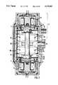
- FIG. 1illustrates a single-tube dashpot with two displacement compartments that communicate through a bypass
- FIG. 2illustrates a vibration-suppression valve system with fluid flowing through pressure-sensitive valves in alignment with the axially displaced plungers
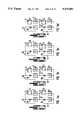
- FIGS. 3a, 3b, 3c and 3dillustrate how the vibration-suppression valve system illustrated in FIG. 2 operates in the vacuum stage
- FIG. 4illustrates a vibration-suppression valve system with fluid flowing through pressure-sensitive valves paralleling the axially displaced plungers
- FIGS. 5a, 5b, 5c and 5dillustrate how the vibration-suppression valve system illustrated in FIG. 4 operates in the compression stage
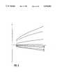
- FIG. 6illustrates characteristic curves attainable with the vibration-suppression valve system
- FIG. 7illustrates another approach to varying the vibration-suppression level on a one-tube dashpot with the vibration-suppression valve system
- FIG. 8illustrates another variation of the vibration-suppression valve system
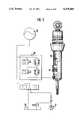
- FIG. 9illustrates a one-tube dashpot with level controls
- FIG. 10illustrates a two-tube dashpot with two displacement compartments communicating through a vibration-suppression valve system.
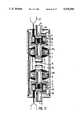
- FIG. 11is a cross-sectional view of another embodiment showing attenuating valves
- FIG. 12is a cross-sectional view of still another embodiment of the system of attenuating valves.
- FIG. 13is a cross-sectional view of another embodiment of FIG. 12;
- FIG. 14is a cross-sectional view of a further embodiment, in accordance with the present invention.
- FIG. 15is a cross-sectional view of a still further embodiment of the system of attenuating valves, according to the present invention.
- the variable single-tube dashpot illustrated in FIG. 1consists essentially of a vibration-suppressing cylinder 17 and piston 18.
- Vibration-suppressing piston 18has a piston rod 19 attached to it, slides in and out of cylinder 17, and is provided with pressure-sensitive vibration-suppression valves 23 and 24.
- Piston rod 19is positioned and sealed off by a seal 20 in cylinder 17.
- Cylinder 17contains a vibration-suppressing fluid.
- Vibration-suppressing piston 18divides the cylinder into an upper displacement compartment 21 and a lower displacement compartment 22. Lower displacement compartment 22 is separated from an equalization compartment 26 by a partitioning piston 25. Partitioning piston 25 is loosely secured in the wall of cylinder 17, allowing displacement of oil by the entering piston rod 19.
- the diameter of cylinder 17is shorter where vibration-suppressing piston 18 enters and leaves than outside that area.
- the cylinderis surrounded at this point by a tube 27. Between cylinder 17 and tube 27 is an annular gap 28.
- a vibration-suppression valve system 29is flanged directly to the dashpot, allowing a bore 15 to communicate with upper displacement compartment 21 and another bore 14 to communicate with lower displacement compartment 22 through annular gap 28.
- FIG. 2illustrates a vibration-suppression valve system with fluid flowing through pressure-sensitive valves 7 and 8 aligned with axially displaced plungers 5 and 6.
- the vibration-suppression valve systemconsists of a cylindrical valve housing 1 that accommodates two aligned vibration-suppressing valves 2, one operating upstream and the other downstream.
- Each vibration-suppressing valve 2consists of an axially displaced electromagnetic plunger 5 or 6 that operates in conjunction with at least one pressure-sensitive valve 7 or 8 aligned with the plunger.
- Each pressure-sensitive valve 7 and 8consists of two resilient-disk valves 7a and 7b or 8a and 8b, two operating upstream and two downstream.
- Each plunger 5 or 6is axially displaced by an electromagnet 11.
- Each electromagnet 11comprises a coil and an armature.
- the plungersblock outlets 3 and 4 when there is no current in the electromagnets and unblock them in the presence of current.
- Housing 1is surrounded by a tube 10, leaving between them a bypass channel 9 in the form of an annular gap. Bypass channel 9 communicates with the inside 16 of the valve through outlets 3 and 4.
- the vibration-suppression valve systemvaries the communication between the dashpot's displacement compartments by way of bores 14 and 15.
- Bypass channel 9communicates with annular gap 28 through bore 15 and lower displacement compartment 22 with the inside 16 of the valve through bore 14.
- FIGS. 3a and 3billustrate how the vibration-suppression valve system illustrated in FIG. 2 operates during the vacuum stage.
- Bore 15is an intake and bore 14 an outlet bore during the vacuum stage and vice versa during the compression stage.
- the vibration-suppression valve systemfunctions as a bypass valve. With outlets 3 and 4 blocked by plungers 5 and 6 as illustrated in FIG. 3, the system is completely disengaged. The only valves in operation are the pressure-sensitive vibration-suppression valves 23 and 24 in vibration-suppressing piston 18.
- FIG. 3bshows outlet 3 open. The fluid can now flow through bore 15, outlet 3, and resilient-disk valve 7b into bore 14 and hence into the dashpot's lower displacement compartment.
- plunger 6unblocks outlet 4 and outlet 3 is closed (FIG. 3c)
- fluidwill flow into bore 14 through bypass channel 9, outlet 4, and resilient-disk valve 8a.
- the softest level of vibration-suppression curveis attained when outlets 3 and 4 are open FIG. 3d). The fluid will enter through bore 15 and flow into bore 14 through outlets 3 and 4 and resilient-disk valves 7b and 8a.
- the vibration-suppression valve systemcan be interposed between the dashpot's displacement compartments and the reservoir.
- FIG. 4Another embodiment of the vibration-suppression valve system is illustrated in FIG. 4.
- the fluid in this systemflows through pressure-sensitive valves 7 and 8 paralleling the axially displaced plungers 5 and 6 that control outlets 3 and 4. Bores 14 and 15 both communicate with the inside 16 of the valve.
- FIGS. 5a and 5billustrate how the vibration-suppression valve system operates during the compression stage.
- Bore 15communicates with the upper displacement compartment and bore 14 with the lower displacement compartment.
- plungers 5 and 6block outlets 3 and 4.
- the fluid entering through bore 14now flows into bore 15, which acts as an outlet bore, only through the similarly oriented resilient-disk valves 8a and 7a.
- the resulting curve of the level of vibration suppression over piston speed(FIG. 6) represents the vibration-suppression valve system's hardest characteristic ZZ.
- FIG. 7illustrates another way of controlling a dashpot's level of vibration suppression with a vibration-suppression valve system 29 between lower displacement compartment 22 and an oil-equalization compartment 30.
- the vibration-suppression curve generated by the valve in this systemis added to the curves generated by pressure-sensitive vibration-suppression valves 23 or 24.
- Vibration-suppression valve system 29is secured to cylinder 17 with a flange 34 and sealed off from the environment and against the wall of the cylinder with seals 35.
- FIG. 8illustrates another version of the vibration-suppression valve system, wherein fluid flows through pressure-sensitive valves 7 and 8 paralleling the axially displaced plungers 5 and 6.
- the bypass channel 9 in this embodimentis constituted by a tube 31 in housing 1 between the outlets 3 and 4 controlled by plungers 5 and 6.
- Tube 31is sectioned between pressure-sensitive valves 7 and 8, providing an outlet 12 to the inside 16 of the valve.
- Tube sections 31a and 31bsimultaneously support pressure-sensitive valves 7 and 8, which are secured with nuts 32 and 33.
- the vibration-suppression valve systemcan be employed without any problem as represented in FIG. 9.
- fluidWhen the vehicle is Jacked up, fluid will be pumped into the dashpot's lower displacement compartment 22, and vibration-suppression valve system 29 will establish the corresponding curve.
- vibration-suppression valve system 29When the vehicle is suspended, fluid will be forced out of lower displacement compartment 22 and into a high-pressure reservoir 35 by vibration-suppression valve system 29 as it generates the adjusted level of vibration-suppression curve to compensate for the volume of the entering piston rod 19.
- the systemalso includes a supply tank 36, a pump 37, and the requisite controls.
- the two-tube dashpot illustrated in FIG. 10consists essentially of a vibration-suppression cylinder 17 with a vibration-suppressing piston 18 attached to a piston rod 19 and having pressure-sensitive vibration-suppression valves 23 and 24 mounted on it traveling in and out.
- An external cylinder 38is mounted concentrically around vibration-suppression cylinder 17, leaving an equalization compartment 26.
- Vibration-suppression cylinder 17is divided into displacement compartments 21 and 22 by a vibration-suppressing piston 18.
- Lower displacement compartment 22communicates with equalization compartment 26 through a valve 39 in the base, allowing compensation for the volume expelled by the entering piston rod 19.
- Upper displacement compartment 21communicates with lower displacement compartment 22 through channel 28 and through vibration-suppression valve system 29, which is currently acting as a bypass valve in relation to pressure-sensitive vibration-suppression valves 23 and 24.
- vibration-suppression valve systemit is on the other hand also possible to exploit the vibration-suppression valve system to create a variable communication for the fluid between upper displacement compartment 21 and equalization compartment 6 or between lower displacement compartment 22 and equalization compartment 26.
- the vibration-suppression valve systemis engaged to adapt the vibration-suppressing properties of the dashpot to the particular state of the vehicle or road conditions.
- Sensorsdetermine the parameters, such as load, vehicle speed, body acceleration, etc.
- the system 29 of attenuating valves illustrated in FIG. 11comprises a cylindrical valve housing 1 that accommodates two coaxially opposed shock-absorbing valves 2.
- Each shock-absorbing valve 2comprises an electromagnetically displaced bolt 5 and 6 and a pressure-sensitive valve 7 and 8.
- Bolts 5 and 6operate in conjunction with ports 3 and 4.
- Pressure-sensitive valves 7 and 8comprise spring-loaded disk valves 7a & 7b and 8a & 8b that open and close in accordance with the pressure of the fluid.
- Bolts 5 and 6are each moved subject to an electromagnet 11 and are positioned to ensure that ports 3 and 4 are closed when no current flows through the electromagnet and are open when current flows through it. In the event of such a malfunction as a power failure or broken cable accordingly, the dashpot's attenuating force will automatically shift to the hardest performance curve.
- the flow channel 9 between the ports 3 and 4 that are adjusted by bolts 5 and 6extends from the outer surface of a pipe 10 accommodated inside housing i and the inner surface of the housing.
- Pipe 10simultaneously constitutes an interior accommodation 6 for pressure-sensitive valves 7 and 8.
- Flow channel 9also accommodate at least one port 12 that opens between the valves into their interior accommodation 6.
- variable communication with the dashpot and, when it is employed in level regulation, with the level regulator,is by way of fluid-line connections 14 and 15.
- Connections 14 and 15are in the form of sections 42 and 43 of pipe that fit into the ends 40 and 41 of system 29 of attenuating valves.
- both electromagnets 11 and annular bolts 5 and 6surround sections 42 and 43.
- Fluid-flow connections 14 and 15terminate in an accommodation 16 for pressure-sensitive valves 7 and 8 and accordingly constitute a direct communication between each pressure-sensitive valve and the ports 3 and 4 accordingly opened and closed by bolts 5 and 6.
- FIG. 12illustrates still another embodiment of the system of attenuating valves.
- Flow channel 9is in this event represented by a pipe 31 accommodated in valve housing 1 between the ports 3 and 4 controlled by bolts 5 and 6.
- the port 12 leading into the interior accommodation 16 for pressure-sensitive valves 7 and 8is constituted by a gap in pipe 31 between the valves. These valves are mounted on sections 31a and 31b of pipe 31.
- Fluid-line connections 14 and 15are constituted in this embodiment by openings in the ends 44 and 45 of housing 1 and by channels between the housing 46 of electromagnets 11 and the inner surface of valve housing 15.
- the ends 44 and 45 of housing 1secure electromagnets 11 above housing 46. Electric connections 47 extend out through the ends.
- FIG. 13illustrates the system 29 of attenuating valves illustrated in FIG. 12 with a radial fluid-line connection 15 and an axial fluid-line connection 14 extending out of end 44.
- Connection 15is positioned in this case between pressure-sensitive valve 8 and port 4.
- the bolts 5 and 6 in the embodiment illustrated in FIG. 14are accommodated axially and coaxially opposed along with their associated ports 3 and 4 and electromagnets 11 inside, and pressure-sensitive valve 7 and 8 axially out valve outside, the sectioned housing 1.
- Each pressure-sensitive valve 7 and 8is in an associated accommodation 16a and 16b in the form of a housing 48.
- Direct communication between axial fluid-flow connections 14 and 15 and their associated pressure-sensitive valves 7 and 8is established by at least one bore 49 and 50.
- Direct connection between fluid-line connections 14 and 15 and the ports 3 and 4 subject to bolts 5 and 6is established through bore 49 or bore 50 in a housing 48, through at least one other bore 51 or 52, and a channel 53 between housing 48 and valve housing 1.
- the two attenuating valves 2communicate through flow channel 9.
- the pressure-sensitive valves 7 and 8are accommodated axially outside and the bolts 5 and 6 that open and close ports 3 and 4 axially inside in valve housing 1 in the system 29 of attenuating valves in the embodiment illustrated in FIG. 15.
- Fluid-flow connections 14 and 15extend along the channel 53 of the particular attenuating valve 2 and accordingly communicate directly with ports 3 or 4 and, by way of bores 51 and 52, with pressure-sensitive valve 7 or 8.
Landscapes
- Engineering & Computer Science (AREA)
- General Engineering & Computer Science (AREA)
- Mechanical Engineering (AREA)
- Fluid-Damping Devices (AREA)
Abstract
Description
Claims (31)
Priority Applications (1)
| Application Number | Priority Date | Filing Date | Title |
|---|---|---|---|
| US08/164,418US5375683A (en) | 1992-01-17 | 1993-12-09 | Controllable vibration damper for motor vehicles |
Applications Claiming Priority (6)
| Application Number | Priority Date | Filing Date | Title |
|---|---|---|---|
| DE4201200 | 1992-01-17 | ||
| DE4201200 | 1992-01-17 | ||
| DE4216987 | 1992-05-22 | ||
| DE4216987ADE4216987C2 (en) | 1992-01-17 | 1992-05-22 | Adjustable vibration damper for motor vehicles |
| US493893A | 1993-01-15 | 1993-01-15 | |
| US08/164,418US5375683A (en) | 1992-01-17 | 1993-12-09 | Controllable vibration damper for motor vehicles |
Related Parent Applications (1)
| Application Number | Title | Priority Date | Filing Date |
|---|---|---|---|
| US493893AContinuation-In-Part | 1992-01-17 | 1993-01-15 |
Publications (1)
| Publication Number | Publication Date |
|---|---|
| US5375683Atrue US5375683A (en) | 1994-12-27 |
Family
ID=27203310
Family Applications (1)
| Application Number | Title | Priority Date | Filing Date |
|---|---|---|---|
| US08/164,418Expired - LifetimeUS5375683A (en) | 1992-01-17 | 1993-12-09 | Controllable vibration damper for motor vehicles |
Country Status (1)
| Country | Link |
|---|---|
| US (1) | US5375683A (en) |
Cited By (41)
| Publication number | Priority date | Publication date | Assignee | Title |
|---|---|---|---|---|
| US5540309A (en)* | 1993-12-16 | 1996-07-30 | August Bilstein Gmbh & Co Kg | Hydraulic cylinder sealing structure |
| US5588510A (en)* | 1995-09-25 | 1996-12-31 | Husco International, Inc. | Variable damping force shock absorber |
| US5624010A (en)* | 1993-12-08 | 1997-04-29 | August Bilstein Gmbh & Co. | Regulable shock-absorption valve system for the dashpot in a motor vehicle |
| US5860498A (en)* | 1995-10-27 | 1999-01-19 | Fichtel & Sachs Ag | Shock absorber for a motor vehicle |
| US5901820A (en)* | 1996-01-25 | 1999-05-11 | Tokico Ltd. | Hydraulic shock absorber |
| US5996748A (en)* | 1996-03-19 | 1999-12-07 | Tokico Ltd. | Damping force adjusting type hydraulic shock absorber |
| US6019201A (en)* | 1996-07-30 | 2000-02-01 | Board Of Regents Of The University And Community College System Of Nevada | Magneto-rheological fluid damper |
| US6116584A (en)* | 1999-02-27 | 2000-09-12 | Daimlerchrysler Ag | Air spring strut for motor vehicle wheel suspensions |
| US6244398B1 (en)* | 1997-05-15 | 2001-06-12 | K2 Bike Inc. | Shock absorber with variable bypass damping |
| US6382370B1 (en) | 1999-09-01 | 2002-05-07 | K2 Bike, Inc. | Shock absorber with an adjustable lock-out value and two-stage flow restriction |
| US6471018B1 (en) | 1998-11-20 | 2002-10-29 | Board Of Regents Of The University And Community College System On Behalf Of The University Of Nevada-Reno, The University Of Reno | Magneto-rheological fluid device |
| US20050163565A1 (en)* | 2004-01-27 | 2005-07-28 | Quenzi Philip J. | Concrete-chute strike-off device |
| US20060054437A1 (en)* | 2004-08-27 | 2006-03-16 | Ken Furuya | Front fork |
| US20060054435A1 (en)* | 2004-07-27 | 2006-03-16 | Hiroyuki Yamaguchi | Hydraulic shock absorber |
| US20080250844A1 (en)* | 2007-04-02 | 2008-10-16 | Gartner Bill J | Methods and Apparatus for Developing a Vehicle Suspension |
| US7699147B2 (en)* | 2000-12-16 | 2010-04-20 | Thyssenkrupp Bilstein Suspension Gmbh | Regulated dashpot with shock-absorption force controls |
| CN104482101A (en)* | 2014-12-30 | 2015-04-01 | 临沂天一减震器有限公司 | Adjustable four-section damping valve for oil fluid shock absorber |
| US20150369324A1 (en)* | 2012-12-07 | 2015-12-24 | Thyssenkrupp Bilstein Gmbh | Damper for a Vehicle Having a Flange for Connecting an External Module Tube |
| US20160160955A1 (en)* | 2014-12-03 | 2016-06-09 | Honda Motor Co., Ltd. | Suspension damper |
| US20160265616A1 (en)* | 2013-11-19 | 2016-09-15 | Thomas Ripa | Damping strut with a hydraulic shock absorber and method for operating the damping strut |
| US9850976B2 (en)* | 2012-12-07 | 2017-12-26 | Thyssenkrupp Bilstein Gmbh | Damper for a vehicle having a flange for connecting an external module tube |
| US20180128339A1 (en)* | 2015-05-20 | 2018-05-10 | Zf Friedrichshafen Ag | Vibration Damper With An External Housing |
| FR3058678A1 (en)* | 2016-11-17 | 2018-05-18 | Peugeot Citroen Automobiles Sa | VARIABLE FLUID INERTIA SUSPENSION DEVICE FOR A VEHICLE TRAIN |
| US10400849B2 (en)* | 2014-12-12 | 2019-09-03 | Zf Friedrichshafen Ag | Adjustable damping valve device |
| US10473179B2 (en) | 2013-11-19 | 2019-11-12 | Thomas Ripa | Movement stage for a hydraulic shock absorber and shock absorber with the movement stage |
| JPWO2018216716A1 (en)* | 2017-05-26 | 2020-02-27 | 日立オートモティブシステムズ株式会社 | Shock absorber |
| US20210131522A1 (en)* | 2019-11-04 | 2021-05-06 | Beijingwest Industries Co., Ltd. | Bracket for attachment with a hydraulic damper assembly and a method of joining a bracket and a hydraulic damper assembly |
| US20210140505A1 (en)* | 2019-11-08 | 2021-05-13 | DRiV Automotive Inc. | Balanced continuously semi-active damper |
| US20210254685A1 (en)* | 2018-09-06 | 2021-08-19 | Thyssenkrupp Bilstein Gmbh | Damper device |
| US20210270342A1 (en)* | 2019-07-18 | 2021-09-02 | Tenneco Automotive Operating Company Inc. | Intake device for a damper having a side collector |
| US11118649B2 (en) | 2019-07-01 | 2021-09-14 | Tenneco Automotive Operating Company Inc. | Damper with side collector and external control valves |
| US20210310535A1 (en)* | 2018-07-27 | 2021-10-07 | Marelli Suspension Systems Italy S.P.A. | Variable-Damping Hydraulic Shock-Absorber for a Vehicle Suspension |
| US11143260B2 (en)* | 2018-12-28 | 2021-10-12 | Tenneco Automotive Operating Company Inc. | Damper with single external control valve |
| US11156261B2 (en) | 2018-12-28 | 2021-10-26 | Tenneco Automotive Operating Company Inc. | Damper with multiple external control valves |
| US11242907B2 (en)* | 2017-09-25 | 2022-02-08 | Zf Friedrichshafen Ag | Adjustable vibration damper |
| US11248677B2 (en)* | 2019-07-18 | 2022-02-15 | Tenneco Automotive Operating Company Inc. | Pre-assembled piston accumulator insert device |
| US20220049753A1 (en)* | 2020-08-14 | 2022-02-17 | DRiV Automotive Inc. | Damper assembly |
| US20220049755A1 (en)* | 2020-08-14 | 2022-02-17 | DRiV Automotive Inc. | Damper assembly including intake valve in fluid chamber |
| US20220252130A1 (en)* | 2019-07-08 | 2022-08-11 | Otto Bock Healthcare Products Gmbh | Actuator and heat store for actuator |
| US11454291B2 (en)* | 2018-12-28 | 2022-09-27 | Tenneco Automotive Operating Company Inc. | Damper with control valves |
| CN116928266A (en)* | 2023-07-27 | 2023-10-24 | 广东溢康通空气弹簧有限公司 | Novel electromagnetic valve of electric control shock absorber |
Citations (5)
| Publication number | Priority date | Publication date | Assignee | Title |
|---|---|---|---|---|
| US4650042A (en)* | 1984-09-22 | 1987-03-17 | Boge Gmbh | Hydraulic adjustable shock absorber |
| US4802561A (en)* | 1986-03-22 | 1989-02-07 | Boge Ag | Adjustable shock absorber |
| US4960188A (en)* | 1988-09-17 | 1990-10-02 | Fichtel & Sachs Ag | Single-tube vibration damper of variable damping force |
| US4986393A (en)* | 1988-02-09 | 1991-01-22 | Boge Ag | Adjustable vibration dampers for motor vehicles |
| US5180039A (en)* | 1989-07-06 | 1993-01-19 | Fichtel & Sachs Ag | Fluid passage unit |
- 1993
- 1993-12-09USUS08/164,418patent/US5375683A/ennot_activeExpired - Lifetime
Patent Citations (5)
| Publication number | Priority date | Publication date | Assignee | Title |
|---|---|---|---|---|
| US4650042A (en)* | 1984-09-22 | 1987-03-17 | Boge Gmbh | Hydraulic adjustable shock absorber |
| US4802561A (en)* | 1986-03-22 | 1989-02-07 | Boge Ag | Adjustable shock absorber |
| US4986393A (en)* | 1988-02-09 | 1991-01-22 | Boge Ag | Adjustable vibration dampers for motor vehicles |
| US4960188A (en)* | 1988-09-17 | 1990-10-02 | Fichtel & Sachs Ag | Single-tube vibration damper of variable damping force |
| US5180039A (en)* | 1989-07-06 | 1993-01-19 | Fichtel & Sachs Ag | Fluid passage unit |
Cited By (63)
| Publication number | Priority date | Publication date | Assignee | Title |
|---|---|---|---|---|
| US5624010A (en)* | 1993-12-08 | 1997-04-29 | August Bilstein Gmbh & Co. | Regulable shock-absorption valve system for the dashpot in a motor vehicle |
| US5540309A (en)* | 1993-12-16 | 1996-07-30 | August Bilstein Gmbh & Co Kg | Hydraulic cylinder sealing structure |
| US5588510A (en)* | 1995-09-25 | 1996-12-31 | Husco International, Inc. | Variable damping force shock absorber |
| US5860498A (en)* | 1995-10-27 | 1999-01-19 | Fichtel & Sachs Ag | Shock absorber for a motor vehicle |
| US5901820A (en)* | 1996-01-25 | 1999-05-11 | Tokico Ltd. | Hydraulic shock absorber |
| US5996748A (en)* | 1996-03-19 | 1999-12-07 | Tokico Ltd. | Damping force adjusting type hydraulic shock absorber |
| US6019201A (en)* | 1996-07-30 | 2000-02-01 | Board Of Regents Of The University And Community College System Of Nevada | Magneto-rheological fluid damper |
| US6244398B1 (en)* | 1997-05-15 | 2001-06-12 | K2 Bike Inc. | Shock absorber with variable bypass damping |
| US6471018B1 (en) | 1998-11-20 | 2002-10-29 | Board Of Regents Of The University And Community College System On Behalf Of The University Of Nevada-Reno, The University Of Reno | Magneto-rheological fluid device |
| US6116584A (en)* | 1999-02-27 | 2000-09-12 | Daimlerchrysler Ag | Air spring strut for motor vehicle wheel suspensions |
| US6382370B1 (en) | 1999-09-01 | 2002-05-07 | K2 Bike, Inc. | Shock absorber with an adjustable lock-out value and two-stage flow restriction |
| US7699147B2 (en)* | 2000-12-16 | 2010-04-20 | Thyssenkrupp Bilstein Suspension Gmbh | Regulated dashpot with shock-absorption force controls |
| US20100155186A1 (en)* | 2000-12-16 | 2010-06-24 | Thyssenkrupp Bilstein Suspension Gmbh | Regulated Dashpot With Shock-Absorption Force Controls |
| US8651251B2 (en) | 2000-12-16 | 2014-02-18 | Thyssenkrupp Bilstein Suspension Gmbh | Regulated dashpot with shock-absorption force controls |
| US20050163565A1 (en)* | 2004-01-27 | 2005-07-28 | Quenzi Philip J. | Concrete-chute strike-off device |
| US20060054435A1 (en)* | 2004-07-27 | 2006-03-16 | Hiroyuki Yamaguchi | Hydraulic shock absorber |
| US20060054437A1 (en)* | 2004-08-27 | 2006-03-16 | Ken Furuya | Front fork |
| US7413064B2 (en)* | 2004-08-27 | 2008-08-19 | Kayaba Industry Co., Ltd. | Front fork |
| US20080250844A1 (en)* | 2007-04-02 | 2008-10-16 | Gartner Bill J | Methods and Apparatus for Developing a Vehicle Suspension |
| US7946163B2 (en) | 2007-04-02 | 2011-05-24 | Penske Racing Shocks | Methods and apparatus for developing a vehicle suspension |
| US9803713B2 (en)* | 2012-12-07 | 2017-10-31 | Thyssenkrupp Bilstein Gmbh | Damper for a vehicle having a flange for connecting an external module tube |
| US20150369324A1 (en)* | 2012-12-07 | 2015-12-24 | Thyssenkrupp Bilstein Gmbh | Damper for a Vehicle Having a Flange for Connecting an External Module Tube |
| US10400844B2 (en)* | 2012-12-07 | 2019-09-03 | Thyssenkrupp Bilstein Gmbh | Damper for a vehicle having a flange for connecting an external module tube |
| US9850976B2 (en)* | 2012-12-07 | 2017-12-26 | Thyssenkrupp Bilstein Gmbh | Damper for a vehicle having a flange for connecting an external module tube |
| US10344819B2 (en) | 2012-12-07 | 2019-07-09 | Thyssenkrupp Bilstein Gmbh | Damper for a vehicle having a flange for connecting an external module tube |
| US20160265616A1 (en)* | 2013-11-19 | 2016-09-15 | Thomas Ripa | Damping strut with a hydraulic shock absorber and method for operating the damping strut |
| US10473179B2 (en) | 2013-11-19 | 2019-11-12 | Thomas Ripa | Movement stage for a hydraulic shock absorber and shock absorber with the movement stage |
| US10047816B2 (en)* | 2013-11-19 | 2018-08-14 | Thomas Ripa | Damping strut with a hydraulic shock absorber and method for operating the damping strut |
| US11578776B2 (en) | 2013-11-19 | 2023-02-14 | Thomas Ripa | Movement stage for a hydraulic shock absorber and shock absorber with the movement stage |
| US20160160955A1 (en)* | 2014-12-03 | 2016-06-09 | Honda Motor Co., Ltd. | Suspension damper |
| US9863494B2 (en)* | 2014-12-03 | 2018-01-09 | Honda Motor Co., Ltd. | Suspension damper |
| US10400849B2 (en)* | 2014-12-12 | 2019-09-03 | Zf Friedrichshafen Ag | Adjustable damping valve device |
| CN104482101A (en)* | 2014-12-30 | 2015-04-01 | 临沂天一减震器有限公司 | Adjustable four-section damping valve for oil fluid shock absorber |
| US20180128339A1 (en)* | 2015-05-20 | 2018-05-10 | Zf Friedrichshafen Ag | Vibration Damper With An External Housing |
| US10514077B2 (en)* | 2015-05-20 | 2019-12-24 | Zf Friedrichshafen Ag | Vibration damper with an external housing |
| WO2018091795A1 (en)* | 2016-11-17 | 2018-05-24 | Psa Automobiles Sa | Suspension device with variable fluid inertia, for a vehicle axle system |
| CN109982875A (en)* | 2016-11-17 | 2019-07-05 | 标致雪铁龙汽车股份有限公司 | The suspension apparatus with convertible fluids inertia for vehicle axle |
| FR3058678A1 (en)* | 2016-11-17 | 2018-05-18 | Peugeot Citroen Automobiles Sa | VARIABLE FLUID INERTIA SUSPENSION DEVICE FOR A VEHICLE TRAIN |
| JPWO2018216716A1 (en)* | 2017-05-26 | 2020-02-27 | 日立オートモティブシステムズ株式会社 | Shock absorber |
| US11242907B2 (en)* | 2017-09-25 | 2022-02-08 | Zf Friedrichshafen Ag | Adjustable vibration damper |
| US11761508B2 (en)* | 2018-07-27 | 2023-09-19 | Marelli Suspension Systems Italy S.P.A. | Variable-damping hydraulic shock-absorber for a vehicle suspension |
| US20210310535A1 (en)* | 2018-07-27 | 2021-10-07 | Marelli Suspension Systems Italy S.P.A. | Variable-Damping Hydraulic Shock-Absorber for a Vehicle Suspension |
| US20210254685A1 (en)* | 2018-09-06 | 2021-08-19 | Thyssenkrupp Bilstein Gmbh | Damper device |
| US12066076B2 (en)* | 2018-09-06 | 2024-08-20 | Thyssenkrupp Bilstein Gmbh | Damper device |
| US11454291B2 (en)* | 2018-12-28 | 2022-09-27 | Tenneco Automotive Operating Company Inc. | Damper with control valves |
| US11143260B2 (en)* | 2018-12-28 | 2021-10-12 | Tenneco Automotive Operating Company Inc. | Damper with single external control valve |
| US11156261B2 (en) | 2018-12-28 | 2021-10-26 | Tenneco Automotive Operating Company Inc. | Damper with multiple external control valves |
| US11118649B2 (en) | 2019-07-01 | 2021-09-14 | Tenneco Automotive Operating Company Inc. | Damper with side collector and external control valves |
| US20220252130A1 (en)* | 2019-07-08 | 2022-08-11 | Otto Bock Healthcare Products Gmbh | Actuator and heat store for actuator |
| US12297889B2 (en)* | 2019-07-08 | 2025-05-13 | Otto Bock Healthcare Products Gmbh | Actuator and heat store for actuator |
| US11248677B2 (en)* | 2019-07-18 | 2022-02-15 | Tenneco Automotive Operating Company Inc. | Pre-assembled piston accumulator insert device |
| US11635122B2 (en)* | 2019-07-18 | 2023-04-25 | Tenneco Automotive Operating Company Inc. | Intake device for a damper having a side collector |
| US20210270342A1 (en)* | 2019-07-18 | 2021-09-02 | Tenneco Automotive Operating Company Inc. | Intake device for a damper having a side collector |
| US11512758B2 (en)* | 2019-11-04 | 2022-11-29 | Beijingwest Industries Co., Ltd. | Bracket for attachment with a hydraulic damper assembly and a method of joining a bracket and a hydraulic damper assembly |
| US20210131522A1 (en)* | 2019-11-04 | 2021-05-06 | Beijingwest Industries Co., Ltd. | Bracket for attachment with a hydraulic damper assembly and a method of joining a bracket and a hydraulic damper assembly |
| US20210140505A1 (en)* | 2019-11-08 | 2021-05-13 | DRiV Automotive Inc. | Balanced continuously semi-active damper |
| US11719305B2 (en)* | 2019-11-08 | 2023-08-08 | DRiV Automotive Inc. | Balanced continuously semi-active damper |
| US20220049753A1 (en)* | 2020-08-14 | 2022-02-17 | DRiV Automotive Inc. | Damper assembly |
| US11454292B2 (en)* | 2020-08-14 | 2022-09-27 | DRiV Automotive Inc. | Damper assembly |
| US11441633B2 (en)* | 2020-08-14 | 2022-09-13 | DRiV Automotive Inc. | Damper assembly including intake valve in fluid chamber |
| CN114076164A (en)* | 2020-08-14 | 2022-02-22 | DRiV汽车公司 | Damper assembly |
| US20220049755A1 (en)* | 2020-08-14 | 2022-02-17 | DRiV Automotive Inc. | Damper assembly including intake valve in fluid chamber |
| CN116928266A (en)* | 2023-07-27 | 2023-10-24 | 广东溢康通空气弹簧有限公司 | Novel electromagnetic valve of electric control shock absorber |
Similar Documents
| Publication | Publication Date | Title |
|---|---|---|
| US5375683A (en) | Controllable vibration damper for motor vehicles | |
| US5078240A (en) | Adjustable vibration damper with valve body in piston having directional flow control | |
| US5295563A (en) | Active suspension actuator with control flow through the piston rod | |
| US5285878A (en) | Cylinder including a piston with a valve control | |
| US5328004A (en) | Bypass valve assembly for a hydraulic damper | |
| US5303804A (en) | Shock absorber for damping courses of motion of a vehicle | |
| CN101802440B (en) | Semi third tube design | |
| US6296091B1 (en) | Suspension control unit and control valve | |
| US4973854A (en) | Hydraulic shock-absorber and vibration damper with adjustable damping | |
| US4850461A (en) | Shock absorber having a throttle with a variable cross section | |
| US5143185A (en) | Controllable hydraulic vibration damper for automotive vehicles | |
| US9453518B2 (en) | Proportional pressure-regulating valve | |
| US5085299A (en) | Shock absorber with two seat valve | |
| EP0882188B1 (en) | Continuously variable single-tube shock absorber with bidirectional control valve | |
| RU2034179C1 (en) | Actuator for brake systems of vehicles | |
| US20090020382A1 (en) | Piston With An Integral Electrically Operated Adjustment Valve For A Hydraulic Vibration Damper | |
| JPS6179036A (en) | Adjustable hydraulic shock absorber | |
| US6044939A (en) | Vibration damper, for a motor vehicle, with adjustable damping force | |
| JPH0356334B2 (en) | ||
| US20070000743A1 (en) | Adjustable damping force hydraulic shock absorber | |
| CN101541571A (en) | Shock absorber with stepless semi-active valve | |
| WO2007149197A1 (en) | Bidirectional force feedback poppet valve | |
| WO2007149192A2 (en) | Poppet valve | |
| CN107567552A (en) | Adjustable vibration-damper | |
| JP2021531441A (en) | Variable damping hydraulic shock absorbers for vehicle suspension |
Legal Events
| Date | Code | Title | Description |
|---|---|---|---|
| AS | Assignment | Owner name:MERCEDES-BENZ AG, GERMANY Free format text:ASSIGNMENT OF ASSIGNORS INTEREST;ASSIGNORS:HUANG, ZHEN;BETSCH, HANS J.;SCHEERER, HANS;AND OTHERS;REEL/FRAME:006803/0237 Effective date:19931015 | |
| FEPP | Fee payment procedure | Free format text:PAYOR NUMBER ASSIGNED (ORIGINAL EVENT CODE: ASPN); ENTITY STATUS OF PATENT OWNER: LARGE ENTITY | |
| FEPP | Fee payment procedure | Free format text:PAYOR NUMBER ASSIGNED (ORIGINAL EVENT CODE: ASPN); ENTITY STATUS OF PATENT OWNER: LARGE ENTITY Free format text:PAYER NUMBER DE-ASSIGNED (ORIGINAL EVENT CODE: RMPN); ENTITY STATUS OF PATENT OWNER: LARGE ENTITY | |
| STCF | Information on status: patent grant | Free format text:PATENTED CASE | |
| FPAY | Fee payment | Year of fee payment:4 | |
| AS | Assignment | Owner name:DAIMLER-BENZ AKTIENGESELLSCHAFT, GERMANY Free format text:MERGER;ASSIGNOR:MERCEDES BENZ AG;REEL/FRAME:009360/0826 Effective date:19970605 | |
| AS | Assignment | Owner name:DAIMLERCHRYSLER AG, GERMANY Free format text:MERGER;ASSIGNOR:DAIMLER-BENZ AKTIENGESELLSCHAFT;REEL/FRAME:010133/0556 Effective date:19990108 | |
| FPAY | Fee payment | Year of fee payment:8 | |
| FPAY | Fee payment | Year of fee payment:12 |