US5373845A - Apparatus and method for forward looking volume imaging - Google Patents
Apparatus and method for forward looking volume imagingDownload PDFInfo
- Publication number
- US5373845A US5373845AUS07/887,473US88747392AUS5373845AUS 5373845 AUS5373845 AUS 5373845AUS 88747392 AUS88747392 AUS 88747392AUS 5373845 AUS5373845 AUS 5373845A
- Authority
- US
- United States
- Prior art keywords
- transducer
- scanning
- scanning system
- scan
- probe
- Prior art date
- Legal status (The legal status is an assumption and is not a legal conclusion. Google has not performed a legal analysis and makes no representation as to the accuracy of the status listed.)
- Expired - Fee Related
Links
- 238000003384imaging methodMethods0.000titleclaimsabstractdescription34
- 238000000034methodMethods0.000titleclaimsdescription8
- 239000000523sampleSubstances0.000claimsabstractdescription65
- 230000033001locomotionEffects0.000claimsdescription19
- 238000003780insertionMethods0.000claims1
- 230000037431insertionEffects0.000claims1
- 238000002604ultrasonographyMethods0.000abstract1
- 238000006073displacement reactionMethods0.000description22
- 210000004204blood vesselAnatomy0.000description13
- 239000007788liquidSubstances0.000description6
- 239000000463materialSubstances0.000description6
- 239000002872contrast mediaSubstances0.000description5
- 230000007170pathologyEffects0.000description5
- 230000001174ascending effectEffects0.000description4
- 238000002592echocardiographyMethods0.000description4
- 239000000835fiberSubstances0.000description4
- 238000012285ultrasound imagingMethods0.000description4
- 230000002792vascularEffects0.000description4
- 210000001367arteryAnatomy0.000description3
- 239000008280bloodSubstances0.000description3
- 210000004369bloodAnatomy0.000description3
- 230000009931harmful effectEffects0.000description3
- 230000003287optical effectEffects0.000description3
- 208000031481Pathologic ConstrictionDiseases0.000description2
- FAPWRFPIFSIZLT-UHFFFAOYSA-MSodium chlorideChemical compound[Na+].[Cl-]FAPWRFPIFSIZLT-UHFFFAOYSA-M0.000description2
- 238000010420art techniqueMethods0.000description2
- 208000021328arterial occlusionDiseases0.000description2
- 210000001124body fluidAnatomy0.000description2
- 230000006378damageEffects0.000description2
- 230000007423decreaseEffects0.000description2
- 230000001419dependent effectEffects0.000description2
- 238000002594fluoroscopyMethods0.000description2
- 239000003550markerSubstances0.000description2
- 230000005855radiationEffects0.000description2
- 230000036262stenosisEffects0.000description2
- 208000037804stenosisDiseases0.000description2
- 244000273618Sphenoclea zeylanicaSpecies0.000description1
- 208000027418Wounds and injuryDiseases0.000description1
- 238000002399angioplastyMethods0.000description1
- 238000004590computer programMethods0.000description1
- 238000007887coronary angioplastyMethods0.000description1
- 230000001627detrimental effectEffects0.000description1
- 201000010099diseaseDiseases0.000description1
- 208000037265diseases, disorders, signs and symptomsDiseases0.000description1
- 239000013536elastomeric materialSubstances0.000description1
- 208000015181infectious diseaseDiseases0.000description1
- 208000014674injuryDiseases0.000description1
- 238000000608laser ablationMethods0.000description1
- 230000004807localizationEffects0.000description1
- 230000009972noncorrosive effectEffects0.000description1
- 210000004872soft tissueAnatomy0.000description1
- 229910001220stainless steelInorganic materials0.000description1
- 239000010935stainless steelSubstances0.000description1
- 238000002560therapeutic procedureMethods0.000description1
- 210000001519tissueAnatomy0.000description1
Images


Classifications
- A—HUMAN NECESSITIES
- A61—MEDICAL OR VETERINARY SCIENCE; HYGIENE
- A61B—DIAGNOSIS; SURGERY; IDENTIFICATION
- A61B8/00—Diagnosis using ultrasonic, sonic or infrasonic waves
- A61B8/42—Details of probe positioning or probe attachment to the patient
- A61B8/4272—Details of probe positioning or probe attachment to the patient involving the acoustic interface between the transducer and the tissue
- A61B8/4281—Details of probe positioning or probe attachment to the patient involving the acoustic interface between the transducer and the tissue characterised by sound-transmitting media or devices for coupling the transducer to the tissue
- A—HUMAN NECESSITIES
- A61—MEDICAL OR VETERINARY SCIENCE; HYGIENE
- A61B—DIAGNOSIS; SURGERY; IDENTIFICATION
- A61B8/00—Diagnosis using ultrasonic, sonic or infrasonic waves
- A61B8/12—Diagnosis using ultrasonic, sonic or infrasonic waves in body cavities or body tracts, e.g. by using catheters
- A—HUMAN NECESSITIES
- A61—MEDICAL OR VETERINARY SCIENCE; HYGIENE
- A61B—DIAGNOSIS; SURGERY; IDENTIFICATION
- A61B8/00—Diagnosis using ultrasonic, sonic or infrasonic waves
- A61B8/44—Constructional features of the ultrasonic, sonic or infrasonic diagnostic device
- A61B8/4444—Constructional features of the ultrasonic, sonic or infrasonic diagnostic device related to the probe
- A61B8/445—Details of catheter construction
- A—HUMAN NECESSITIES
- A61—MEDICAL OR VETERINARY SCIENCE; HYGIENE
- A61B—DIAGNOSIS; SURGERY; IDENTIFICATION
- A61B8/00—Diagnosis using ultrasonic, sonic or infrasonic waves
- A61B8/44—Constructional features of the ultrasonic, sonic or infrasonic diagnostic device
- A61B8/4444—Constructional features of the ultrasonic, sonic or infrasonic diagnostic device related to the probe
- A61B8/4461—Features of the scanning mechanism, e.g. for moving the transducer within the housing of the probe
Definitions
- This inventionrelates to an ultrasonic imaging system and, more particularly, to such a system that employs an ultrasonic transducer which is mounted on a probe member to provide an ultrasonic scan of an area or volume in front of the probe.
- a prior art technique of providing an image of a lumenemploys X-ray fluoroscopy.
- X-ray fluoroscopya contrast agent is sent through an artery of interest.
- the contrast agentis visible under X-ray radiation which enables an X-ray system to provide an image of the arterial obstruction.
- X-ray imaging techniqueshave disadvantages.
- An X-ray image of an arterial obstructionis a profile of the contrast agent as it flows through the artery. Therefore, the images provided are generally of the contrast agent in a single plane of view, not of the tissue.
- the true lumen diameteris generally not provided by these images.
- the characteristics of the plaque within the arteryare not provided, which is important in determining the success of a possible angioplasty procedure.
- Another disadvantageis the potential harmful effects of the radiation to the patient and attending medical personnel.
- a transducerIn prior art ultrasound imaging systems, a transducer is utilized that emits an ultrasonic imaging beam. The transducer is fastened about the outside circumference of a catheter and the ultrasonic imaging beam emanates perpendicular to the catheter. Because of this, the transducer only provides an image of areas on the sides of the catheter, as shown in FIG. 1. Such prior art catheter side scanning systems generally do not provide an image of the central region of the lumen in front of the catheter tip. This is a disadvantage since it is the central region of the lumen that should be imaged in order to characterize a severe stenosis.
- prior art side scanning systemsproceed blindly forward through the blood vessel as the catheter is moved. This forward, unchecked motion may inadvertently cause the catheter to contact the blood vessel wall and shear off material attached to the blood vessel wall so that it is pushed into the bloodstream.
- prior art side scanning systemsgenerally do not provide for the guidance of therapeutic procedures such as laser ablation or mechanical atherectomy.
- prior art catheter side scanning systemsprovide a plane image on the side of the catheter, which prevents a substantial portion of many pathologies from being characterized.
- U.S. Pat. No. 4,998,916 to Hammerslag, et aldiscloses a steerable catheter device for coronary angioplasty applications.
- the devicecan negotiate the tortuous character of a vascular system.
- Fiber optic bundlesare located at the tip of the device that illuminate an area in front of the device.
- a transparent inert liquidsuch as a saline solution, must be discharged into the vascular system.
- the transparent liquidis discharged in front of the device and displaces blood from the front of the device. This enables a user to view through the liquid and observe the volume in front of the device.
- the present inventioncircumvents the drawbacks in the prior art by providing an ultrasonic scanning system that can image an area or volume in front of the probe as the probe is moved through the lumen.
- a scanning system for ultrasonic imagingcomprising a probe having an exploratory end and an opposite end, a transducer nutatably mounted to said exploratory end, moving means coupled to said opposite end for moving said probe to a selected position along a given path, a plurality of cables having first and second ends, wherein said transducer is coupled to said first ends, and scanning means coupled to said second ends for causing said transducer to nutate and provide a scan in front of said transducer and towards said selected position along said path.
- FIG. 1shows a prior art ultrasonic side scanning system
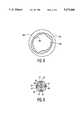
- FIG. 2depicts a present invention embodiment for an exploratory end of a probe employing three cables;
- FIG. 3is a top view of the present invention apparatus
- FIG. 4is a side view along section line 4--4 of FIG. 3;
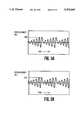
- FIGS. 5A and 5Bshow displacements as a function of time of two driveshafts of the present invention
- FIG. 6shows an exploratory end of the present invention scanning a body lumen
- FIG. 7depicts a spiral scan pattern produced by the displacements of FIGS. 5A and 5B;
- FIG. 8shows an image of the body lumen scanned in FIG. 6
- FIG. 9is an alternate embodiment of the exploratory end employing four cables
- FIGS. 10A-10Cshow displacements as a function of time of each of three driveshafts of a present invention embodiment employing three electromagnetic drives;
- FIGS. 11A-11Bshow displacements as a function of time of each of four driveshafts of a present invention embodiment employing four electromagnetic drives;
- FIG. 12depicts a raster scan pattern produced by the displacements of FIGS 11A-11B.
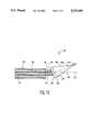
- FIG. 13is a present invention embodiment employing a hinged transducer.
- FIG. 1a prior art ultrasonic catheter side scanning system 20 is shown positioned within a lumen 22 of a blood vessel 24.
- the system 20comprises a catheter 26 having a central longitudinal axis 28.
- a transducer 30is positioned on the side of the catheter 26.
- An imaging device(not shown) is coupled to the transducer 30 to enable the transducer 30 to emit an ultrasonic beam 32.
- the ultrasonic beam 32emanates perpendicular to the central longitudinal axis 28.
- the transducer 30In order to produce an image of an obstruction 34, the transducer 30 must be moved and rotated in the lumen 22 so that the ultrasonic beam 32 intersects the obstruction 34.
- the prior art side scanning system 20provides images of obstructions that the tip 36 of the catheter 26 has already passed. Images in front of the catheter tip 36 are generally not provided by the system shown in FIG. 1.
- the catheter 26may contact obstructions within the blood vessel 24 or the actual wall of the blood vessel 24. Contact by the catheter 26 may dislodge a potentially harmful piece of the obstruction 34 into the blood vessel 24 or may actually damage the blood vessel 24.
- a plane image on the side of the catheter 26is provided, which prevents a substantial portion of the obstruction 34 from being characterized.
- the probe 48may be relatively flexible in order to accommodate tortuous intravascular cavities. Alternately, the probe 48 may be substantially rigid in order to advance the probe 48 directly into a body cavity.
- a transducer 40Positioned at a forward end of the probe 48 is a transducer 40.
- the transducer 40is T-shaped in a side cross section, having a forward facing concave head 41 and a rearwardly extending hollow stem 43.
- a cable attachment plate 37is positioned behind the transducer 40.
- the plate 37is positioned on an outside circumference of a ball 44.
- the stem 43extends through the plate 37 and into the ball 44 and is affixed to the plate 37 and ball 44.
- the ball 44is positioned within a socket 46, forming a ball and socket joint.
- the ball 44pivots relative to the socket 46, thereby allowing the plate 37 and transducer 40 to move according to the swivel of the ball 44 within the socket 46.
- the socket 46is formed in a hollow socket member 39 which is affixed to a probe tip 42.
- a signal wire 58is electrically connected to transducer 40, providing the transducer 40 with ultrasonic signals.
- the signal wire 58extends through the stem 43, the socket member 39 and a central hollow 64 in the probe 48.
- a relief 62is formed on the ball 44 surrounding signal wire 58, allowing the ball 44 a free range of swivel motion without contacting the signal wire 58.
- a plurality of cableseach having ball shaped ends, extend through corresponding channels 47.
- the cablesare free moving within the channels 47 and travel the length of probe 48.
- first 52, second 54 and third 56 (not shown due to side cross sectional view) cablesare utilized, each having corresponding first 59, second 61 and third (not shown) ball shaped ends.
- the first 59, second 61 and third ball shaped endsare pivotally affixed within the plate 37, each forming ball and socket joints, which will be referred to as pivot joints. This allows the plate 37 to nutate about each pivot joint.
- the movement of the plate 37is controlled by movement of the first 52, second 54 and third 56 cables within the channels 47. Consequently, this allows the ball 44 to move within the socket 46 and thus nutate the transducer as will be explained hereinafter.
- the cableshold the ball 44 within the socket 46.
- the cablescan be fabricated from a sterilizable, non-corrosive material such as stainless steel.
- the first 52, second 54 and third 56 cablesare symmetrically positioned around the plate 37.
- An enclosure 45 having an internal chamber 49is positioned on the exploratory end 38 of the probe 48.
- the enclosurehas a reversed "C" shape in a side cross section having ends 50 secured to the probe 48.
- the transducer 40, plate 37, ball 44, socket member 39 and forward ends of the first 52, second 54 and third 56 cablesare positioned within the internal chamber 49 and are encapsulated within the enclosure 45.
- the internal chamber 49is sealed and filled with a liquid 51 such as a saline solution that does not substantially affect ultrasonic energy emitted by the transducer 40 and allows the transducer 40 to nutate as previously described.
- the enclosure 45may be fabricated from any suitable material such as an elastomeric material that also does not substantially affect ultrasonic energy emitted by the transducer 40.
- the enclosure 45serves to protect a patient from injury that may occur due to contact of the transducer 45 or plate 37 or other element with an internal body cavity or intravascular lumen as the transducer 40 nutates.
- the enclosure 45protects the above described encapsulated elements from being contaminated from blood or other bodily fluids during use.
- FIG. 3shows a top view of the present invention apparatus 67.
- the exploratory end 38 of the probe 48 shown in FIG. 2is now depicted as a smaller part of the overall scanning system.
- a distal end 82 of the probe 48, opposite the exploratory end 38,is fastened to the longer arm of a tension bracket 68.
- the tension bracket 68is of a reversed "L" shaped configuration with a long upstanding arm and a shorter base arm and will be designated as an L shaped bracket.
- the L shaped bracket 68is pivotally attached to a platform 70.
- the shorter arm of the L shaped bracket 68is fastened to an end of a spring 71.
- An opposite end of the spring 71is fastened to the platform 70.
- the spring 71holds the L-shaped bracket 68 in a biased position.
- the signal wire 58Emerging from the distal end 82 of the probe 48 is the signal wire 58 that is electrically connected to the transducer 40 and the first 52, second 54 and third 56 cables that control the position of the transducer 40.
- the signal wire 58is coupled to an ultrasonic imaging system 144 having a display 146 that produces and receives ultrasonic signals, as will later be described.
- the first 52, second 54 and third 56 cablespass over a series of pulleys, positioned on the platform 70, and each cable is connected to a disc 76.
- the first cable 52is passed over a first pulley 72.
- the first pulley 72guides the first cable 52 to a first adjustable pulley 74.
- the first adjustable pulley 74has a variable radius of rotation and is used to adjust tension in the first cable 52.
- the first cable 52is then guided by the first adjustable pulley 74 to the disc 76.
- the second cable 54is passed over a second pulley 78.
- the second pulley 78guides the second cable 54 to a second adjustable pulley 80.
- the second adjustable pulley 80has a variable radius of rotation and is used to adjust tension in the second cable 54 in the manner previously described.
- the second cable 54is then guided by the second adjustable pulley 80 to the disc 76.
- the third cable 56is passed over a third pulley 82.
- the third pulley 82guides the third cable 56 to a third adjustable pulley 84.
- the third adjustable pulley 84has an adjustable radius of rotation and is used to adjust tension in the third cable 56.
- the third adjustable 84guides the third cable 56 to a fourth pulley 86.
- the third cable 56is then passed over the fourth pulley 86 and guided to the disc 76.
- the first 52, second 54 and third 56 cablesare fastened to an outside circumference of the disc 76 in a symmetrically disposed manner, with each cable secured 120° apart from the next.
- FIG. 4is a side view of the present invention along section line 4--4 of FIG. 3.
- the disc 76rests on the platform 70.
- the platform 70is releasably secured to a main mounting element 94 by fasteners 92.
- An aperture 90is formed through the main mounting element 94 and platform 70.
- a spindle 88passes through the aperture 90, connecting the disc 76, positioned on top of the platform 70, to hub 112 positioned below the main mounting element 94.
- the spindle 88may be unistructurally formed as part of the hub 112. However, it is preferred that the disc 76 be removable from the spindle 88 to enable the removal of the platform 70.
- the hub 112is supported in place by a flexible rod 138 which is fastened to a baseplate 140. Symmetrically connected to the hub 112 are a plurality of drivewires. The drivewires are connected to a corresponding plurality of driveshafts and electromagnetic drivers.
- first 114 and second 120 drivewiresare used.
- the first 114 and second 120 drivewires extending from the hub 112are connected to corresponding first 116 and second 122 driveshafts.
- the first 116 and second 122 driveshaftsare driven by corresponding first 118 and second 124 electromagnetic drivers that extend and retract or vibrate the driveshafts at a desired frequency.
- the first 118 and second 124 electromagnetic driversare attached to the bottom surface of the main mounting element 94.
- the first 118 and second 124 electromagnetic driversare coupled to a programmable power controller 136 that controls the amplitude and frequency at which the electromagnetic drivers operate the first 116 and second 122 driveshafts and thus the first 114 and second 120 drivewires.
- the transducer 40Since the present invention apparatus uses a transducer 40 to ultrasonically create an image, the transducer 40 must be scanned across the desired area of interest. During operation, the scanning function of the transducer 40 is ultimately controlled by the programmable power controller 136. To scan the transducer 40, a desired signal current is provided to the first 118 and second 124 electromagnetic drivers. Although any signal current can be used, the preferred signal current will cause the first 118 and second 124 electromagnetic drivers to produce sinusoidal vibrations in the first 116 and second 122 driveshafts. Additionally, it is preferred that the sinusoidal vibrations of the first 116 and second 122 driveshafts be equally out of phase with the other. For example, in the shown embodiment there are two electromagnetic drivers.
- the first electromagnetic drive 118vibrate its corresponding first driveshaft 116 at a frequency 90 degrees out of phase with the second driveshaft 122.
- the second driveshaft 122it would be desirable that their corresponding driveshafts be 120 degrees out of phase.
- the first 118 and second 124 electromagnetic driversvibrate the first 116 and second 122 driveshafts which produce vibrations in the first 114 and second 120 drivewires.
- a preferred vibration patternis shown for each driveshaft.
- FIG. 5Aa sinusoidal displacement with respect to time of the first driveshaft 116 is shown.
- the sinusoidal displacementbegins with a minimum amplitude.
- the amplitudeincreases linearly with each sinusoidal displacement and reaches a maximum of approximately 0.030 inch.
- the amplitudethen decreases linearly to the minimum amplitude.
- the frequency of the displacement motionis approximately 150 Hz.
- FIG. 5Bshows a sinusoidal displacement with respect to time of the second driveshaft 122.
- the sinusoidal displacement of the pattern of FIG. 5Bis 90 degrees out of phase with the sinusoidal displacement of the first pattern shown in FIG. 5A.
- the sinusoidal displacement of the second driveshaft 122is otherwise identical to the sinusoidal displacement of the first driveshaft 116.
- the sinusoidal displacement of the first 116 and second 122 driveshaftsis transferred to the first 114 and second 120 drivewires.
- the displacement of the drivewiresis transferred to the hub 112.
- the hub 112is supported in its nominal position by the flexible rod 138.
- the flexible rod 138deforms when biased, the hub 112 will move from its nominal position in accordance with the forces exerted on it by the first 114 and second 120 drivewires.
- the movement of the hub 112is transferred to the disc 76 through the spindle 88.
- the movement of the disc 76therefore, causes the first 52, second 54 and third 56 cables to move in a corresponding fashion.
- the movement of the first 52, second 54 and third cablesis forward through the respective pulley arrangements into the probe 48.
- the first 52, second 54 and third 56 cablesthen cause the plate 37 to move and thus move the ball 44 to within its socket 46, causing the transducer 40 to nutate and provide a scan.
- the movement of the first 52, second 54 and third 56 cables within the probe 48may cause the probe 48 to vibrate. Since vibration of probe 48 is undesirable, the distal end 82 of the probe 48 is attached to the L shaped bracket 68. As previously described, the L shaped bracket 68 is held in a biased position by the spring 71. Vibrations in the probe 48, therefore, cause the L shaped bracket 68 to pivotally move. Consequently, the spring 71 attached to the L shaped bracket 68 is displaced and the vibrations of the probe 48 are damped.
- the probe 48 and enclosure 45are inserted into a patient's body. Consequently, the probe 48 and enclosure 45 come into contact with the patient's blood or other bodily fluids. This requires replacement of the probe 48 and enclosure 45 after use in order to maintain clean and sterilized conditions so that infections and diseases are not spread.
- the removability of the disc 76 and the platform 70enables a doctor or other medical personnel to remove the platform 70 and its elements, including the probe 48, enclosure 45, transducer 40, plate 37, associated pulleys and cables, as an entire platform assembly. The platform assembly may then be quickly replaced by another platform assembly that is sterile, enabling the doctor to proceed with another medical procedure.
- the probe 48bends as it is continuously directed and turned in order to match a labyrinthine path of the intravascular lumen or other body cavity in which it is positioned. It is desirable to provide a scan of the volume in front of the probe tip 42 as the probe 48 bends while being moved in the intravascular lumen.
- the ball 44 supporting the transducer 40is held within its socket 46 by the tension of the first 52, second 54 and third 56 cables. Additionally, in order for the ball 44 to swivel as desired in accordance with the displacements of the first 52, second 54 and third 56 cables, there must be substantially no slack in the length of those cables.
- the probe 48bends as it moves along a path in a lumen, one or more of the first 52, second 54 and third 56 cables that are on the inside of the bend will lose their tension.
- the cable tensionis substantially maintained by the L shaped bracket 68.
- the L shaped bracket 68is fastened to the distal end 82 of the probe 48 and is held in a biased position by the spring 71. As can be ascertained, this causes the probe 48 to maintain a substantially constant tension in the first 52, second 54 and third 56 cables as the probe 48 is being advanced.
- a feedback device(not shown) is coupled to the present invention.
- the feedback devicedetermines a center point of reference for an ultrasonic beam emanating from the transducer 40. Prior to operation, the center point of reference is set.
- the feedback devicecontinuously detects the transducer 40 position and determines whether it is facing substantially forward as desired. If the transducer 40 is not facing substantially forward, the feedback device increases or decreases the scanning motion as required in order to provide a new and corrected point of reference. Consequently, the center point of reference is continuously adjusted as the probe 48 is advanced. This enables the transducer 40 to provide a scan of the area or volume in front of the probe tip 42 as the probe 48 is advanced within an intravascular lumen or other internal cavity.
- the feedback devicemay include a light beam used in conjunction with optical markings on the ball 44 or transducer 40 which are utilized to determine orientation as will be described hereinafter.
- FIG. 6the exploratory end 38 of the present invention probe 48 is shown scanning an oncoming area as it moves within a blood vessel 150.
- the scanning pattern of the transducer 40is dependent upon the displacement of the disc 76 by the first 118 and second 124 electromagnetic drivers.
- the scanning patterncan have any geometry
- the preferred embodiment of the present inventionhas a scanning pattern 154 as shown in FIG. 7 that follows a descending and ascending spiral motion.
- the ascending spiral motionsare shown as solid lines and the descending spiral motions are shown as dotted lines.
- the ascending spiral motiongradually increases and includes a plurality of turns while the descending spiral motion is relatively rapid.
- datamay be collected by the ultrasonic imaging system 144 during the ascending spiral motion which is then utilized to form an image on the display 146.
- the exploratory end 38is positioned within a lumen 148 of a blood vessel 150.
- the blood vessel 150is used by way of example only, and it is understood that other lumens or internal cavities can be scanned by utilizing the present invention.
- the transducer 40emits an ultrasonic beam 152 in the manner previously described.
- the ultrasonic beam 152 emitted from the transducer 40 of the present inventionwill have a focal point 158. Therefore, the transducer 40 can be utilized within a focal zone 160.
- the portion of the area scanned that is in focusis recorded.
- the transducer 40nutates in the spiral manner previously described.
- a spiral scan pattern 154is produced (only one spiral motion is shown for clarity).
- the spiral scan pattern 154is shown imaging material 156 within the lumen 148.
- the material 156can be plaque or any other obstruction that may be found in the lumen 148.
- the ultrasonic beam 152is transmitted and received from the transducer 40 as the transducer 40 is cycled through its scanning pattern.
- the ultrasonic beam 152is generated by the ultrasound imaging systems controller 144, electrically connected to the transducer 40 by the signal wire 58. Reflected ultrasonic beams are also received by the transducer 40 and are read by the ultrasound imaging systems controller 144, utilizing the same signal wire 58.
- An image of an areacan be obtained by emitting an ultrasonic beam and detecting its echo. Echo is generally known in the art as the reflection of an ultrasonic beam from the area or volume being scanned. The distance from the transducer 40 to the area being scanned corresponds to the round trip travel time for the ultrasonic beam 152 to travel from the transducer 40 and to return to the transducer 40. The image in the display 146 is then formed from the echoes of a plurality of spiral scanning patterns that arrive at the transducer 40 at a particular time. As the ultrasonic beam 152 scans a plane of interest, the returning echoes define that plane, which is known in the art as a "C" scan.
- the echoes of the plurality of scanning patternsare received and stored at various time intervals, the echoes describe several different planes that are at distances from the transducer 40 corresponding to their respective round trip travel times.
- a plurality of image planesare provided by each spiral scan pattern 154.
- the image planesmay be on either or both sides of the plane of interest.
- the ultrasonic imaging system 144can provide multiple images over a depth or volume that may be shown in the display 146.
- the multiple image planescan be processed by the ultrasonic imaging system controller 144 to provide a volumetric, three dimensional image on the display 146 of the area or volume in front of the probe 48 as the probe 48 is advanced in the lumen or other internal cavity.
- FIG. 8is a view along section line 8--8 of FIG. 6.
- an image 162is shown that is created by the scanning pattern set forth in FIG. 6.
- the image 162is of the obstructing material 156 lining the blood vessel 150 in front of the transducer 40.
- FIG. 9an alternate embodiment of the present invention is disclosed.
- a cross section of the present invention probe 48is shown containing four cables rather than the three cables previously described.
- Like numeralsindicate like elements.
- a fourth cable 163, identical to the first 52, second 54 and third 56 cables,is added in the alternate embodiment, with each cable positioned in corresponding channels 47.
- the first 52, second 54, third 56 and fourth 163 cablesare located in a circular arrangement and equally spaced.
- the first 52, second 54, third 56 and fourth 162 cablesare fastened to the cable attachment plate 37 in the manner previously described and are symmetrically positioned around the plate 37.
- the signal wire 58is located within the central hollow 64 of the probe 48 and is utilized in the manner previously described.
- a fiber optic cable 59is also positioned within the central hollow 64 and is coupled to the ultrasonic imaging controller 144.
- the ultrasonic imaging controller 144provides a laser signal and the fiber optic element 59 is used to transmit the laser signal.
- the laser signalis used in conjunction with an optical marker which enables the ultrasonic imaging system 144 to detect the position of the ball 44 at the tip of the probe 48.
- the ball 44may be encoded by means of a bar code or any other optical marker. This operates as a feedback control signal for the system to enable the accurate determination of transducer 40 orientation.
- the present inventioncan be readily modified so as to add a third electromagnetic driver.
- a computer programcan be employed that will cause the programmable power controller 144 to displace each output shaft of the electromagnetic drivers.
- FIGS. 10A-10Ca preferred vibration pattern is shown for each driveshaft of the three electromagnetic drivers. As can be seen, the sinusoidal displacements and the amplitudes are similar to those previously described. However, in the alternate embodiment, each driveshaft is 120 degrees out of phase instead of 90 degrees as in the preferred embodiment.
- FIG. 11Ashows the resulting driveshaft displacement of two electromagnetic drivers as a function of time.
- FIG. 11Bshows the driveshaft displacement of the other two electromagnetic drivers as a function of time.
- the resulting motionwill nutate the transducer 40.
- FIG. 12depicts a raster scanning pattern 178 produced by the driveshaft displacements depicted in FIGS. 11A and 11B.
- FIG. 13depicts a cross section of an alternate embodiment of the exploratory end 38.
- a transducer 180having a forward facing concave head 181 and a fiat rear surface 183 is positioned at a forward end of a hollow probe 170.
- the rear surface 183is secured to an end of a hinge 164.
- An opposite end of the hinge 164is fastened to an end of a hollow cylinder 166.
- the hollow cylinder 166is positioned concentrically within the hollow probe 170 and is free to rotate within the hollow probe 170.
- the hollow cylinder 166 and hollow probe 170have a central axis 172.
- An opposite end of the hollow cylinder 166is coupled to a rotating means for rotating (not shown) the hollow cylinder 166.
- An end of the signal wire 58is coupled to the transducer 180.
- the signal wire 58extends through a hollow 176 within the hollow cylinder 166.
- An opposite end of the signal wire 58is coupled to the ultrasonic imaging system 144 previously described.
- a flexible cable 174is coupled to the rear surface 183.
- the cable 174extends through the hollow 176 and is free moving within the hollow cylinder 166.
- An opposite end of the cable 174is coupled to a moving means for moving (not shown) the cable 174.
- the present inventioncan be readily modified to provide the previously described rotating means and moving means. It is understood that the enclosure 45 previously described may be secured to the hollow probe 170 and utilized to encapsulate the transducer 180, hinge 164 signal wire 58 and cable 174.
- the transducer 180emits an ultrasonic beam 182 having a focal point 184 that forms an angle 168 with the central axis 172.
- the rotating meansrotates the hollow cylinder 166 within the hollow probe 170.
- the transducer 180nutates and produces a circular scan corresponding to the angle 168.
- the moving meansmoves the cable 174 relative to the hollow cylinder 166, thus changing the angle 168 as the hollow cylinder 166 rotates.
- a spiral scan patternmay be obtained.
Landscapes
- Health & Medical Sciences (AREA)
- Life Sciences & Earth Sciences (AREA)
- Physics & Mathematics (AREA)
- Biomedical Technology (AREA)
- Medical Informatics (AREA)
- Pathology (AREA)
- Radiology & Medical Imaging (AREA)
- Engineering & Computer Science (AREA)
- Biophysics (AREA)
- Heart & Thoracic Surgery (AREA)
- Nuclear Medicine, Radiotherapy & Molecular Imaging (AREA)
- Molecular Biology (AREA)
- Surgery (AREA)
- Animal Behavior & Ethology (AREA)
- General Health & Medical Sciences (AREA)
- Public Health (AREA)
- Veterinary Medicine (AREA)
- Acoustics & Sound (AREA)
- Ultra Sonic Daignosis Equipment (AREA)
Abstract
Description
Claims (31)
Priority Applications (4)
| Application Number | Priority Date | Filing Date | Title |
|---|---|---|---|
| US07/887,473US5373845A (en) | 1992-05-22 | 1992-05-22 | Apparatus and method for forward looking volume imaging |
| EP93913783AEP0641176B1 (en) | 1992-05-22 | 1993-04-29 | Apparatus for forward volume imaging |
| PCT/US1993/004040WO1993024057A1 (en) | 1992-05-22 | 1993-04-29 | Apparatus and method for forward volume imaging |
| DE69317281TDE69317281T2 (en) | 1992-05-22 | 1993-04-29 | DEVICE FOR IMAGING A SPACE BEFORE THE PROBE |
Applications Claiming Priority (1)
| Application Number | Priority Date | Filing Date | Title |
|---|---|---|---|
| US07/887,473US5373845A (en) | 1992-05-22 | 1992-05-22 | Apparatus and method for forward looking volume imaging |
Publications (1)
| Publication Number | Publication Date |
|---|---|
| US5373845Atrue US5373845A (en) | 1994-12-20 |
Family
ID=25391217
Family Applications (1)
| Application Number | Title | Priority Date | Filing Date |
|---|---|---|---|
| US07/887,473Expired - Fee RelatedUS5373845A (en) | 1992-05-22 | 1992-05-22 | Apparatus and method for forward looking volume imaging |
Country Status (4)
| Country | Link |
|---|---|
| US (1) | US5373845A (en) |
| EP (1) | EP0641176B1 (en) |
| DE (1) | DE69317281T2 (en) |
| WO (1) | WO1993024057A1 (en) |
Cited By (132)
| Publication number | Priority date | Publication date | Assignee | Title |
|---|---|---|---|---|
| US5505088A (en)* | 1993-08-27 | 1996-04-09 | Stellartech Research Corp. | Ultrasound microscope for imaging living tissues |
| WO1996016600A1 (en)* | 1994-11-30 | 1996-06-06 | Boston Scientific Corporation | Acoustic imaging and doppler catheters and guidewires |
| US5606975A (en)* | 1994-09-19 | 1997-03-04 | The Board Of Trustees Of The Leland Stanford Junior University | Forward viewing ultrasonic imaging catheter |
| US5699805A (en)* | 1996-06-20 | 1997-12-23 | Mayo Foundation For Medical Education And Research | Longitudinal multiplane ultrasound transducer underfluid catheter system |
| US5704361A (en)* | 1991-11-08 | 1998-01-06 | Mayo Foundation For Medical Education And Research | Volumetric image ultrasound transducer underfluid catheter system |
| US5713363A (en)* | 1991-11-08 | 1998-02-03 | Mayo Foundation For Medical Education And Research | Ultrasound catheter and method for imaging and hemodynamic monitoring |
| WO1998011823A1 (en) | 1996-09-20 | 1998-03-26 | Cardiovascular Imaging Systems, Inc. | Three-dimensional intraluminal ultrasound image reconstruction |
| US6059731A (en)* | 1998-08-19 | 2000-05-09 | Mayo Foundation For Medical Education And Research | Simultaneous side-and-end viewing underfluid catheter |
| US6066096A (en)* | 1998-05-08 | 2000-05-23 | Duke University | Imaging probes and catheters for volumetric intraluminal ultrasound imaging and related systems |
| WO2000049946A1 (en)* | 1999-02-24 | 2000-08-31 | Echocath, Inc. | Multi-beam diffraction grating imager apparatus and method |
| US6171247B1 (en) | 1997-06-13 | 2001-01-09 | Mayo Foundation For Medical Education And Research | Underfluid catheter system and method having a rotatable multiplane transducer |
| US6198956B1 (en) | 1999-09-30 | 2001-03-06 | Oti Ophthalmic Technologies Inc. | High speed sector scanning apparatus having digital electronic control |
| US6200269B1 (en)* | 1998-05-28 | 2001-03-13 | Diasonics, Ultrasound, Inc. | Forward-scanning ultrasound catheter probe |
| US6264608B1 (en)* | 1996-04-02 | 2001-07-24 | Siemens Aktiengesellschaft | Acoustic therapy apparatus comprising a source of therapeutic acoustic waves and an ultrasound locating means |
| US6306096B1 (en) | 1991-11-08 | 2001-10-23 | Mayo Foundation For Medical Education And Research | Volumetric image ultrasound transducer underfluid catheter system |
| US6306094B1 (en)* | 1996-10-31 | 2001-10-23 | Btg International Limited | Instrument having enhanced ultrasound visibility |
| US6398736B1 (en) | 1999-03-31 | 2002-06-04 | Mayo Foundation For Medical Education And Research | Parametric imaging ultrasound catheter |
| US20020107447A1 (en)* | 1999-07-20 | 2002-08-08 | Scimed Life Systems, Inc. | Imaging catheter and methods of use for ultrasound-guided ablation |
| US6690963B2 (en) | 1995-01-24 | 2004-02-10 | Biosense, Inc. | System for determining the location and orientation of an invasive medical instrument |
| US20040056751A1 (en)* | 2002-09-18 | 2004-03-25 | Byong-Ho Park | Tubular compliant mechanisms for ultrasonic imaging systems and intravascular interventional devices |
| US20040236220A1 (en)* | 2003-05-23 | 2004-11-25 | Parker Willis | Method and system for registering ultrasound image in three-dimensional coordinate system |
| US20060173350A1 (en)* | 2005-01-11 | 2006-08-03 | Scimed Life Systems, Inc. | Systems and methods for three dimensional imaging with an orientation adjustable array |
| US20060241478A1 (en)* | 2005-04-12 | 2006-10-26 | Scimed Life Systems, Inc. | Forward looking imaging guidewire |
| US20060247529A1 (en)* | 2005-04-29 | 2006-11-02 | Rose Harold B | Transurethral ultrasonic imaging system |
| US20070016063A1 (en)* | 2005-05-04 | 2007-01-18 | Byong-Ho Park | Miniature actuator mechanism for intravascular imaging |
| US20070038097A1 (en)* | 2005-07-22 | 2007-02-15 | Crawford Alan D | Introducer |
| US20070106155A1 (en)* | 2005-10-31 | 2007-05-10 | Novelis, Inc. | System and method for reducing angular geometric distortion in an imaging device |
| US20070167804A1 (en)* | 2002-09-18 | 2007-07-19 | Byong-Ho Park | Tubular compliant mechanisms for ultrasonic imaging systems and intravascular interventional devices |
| US20070250000A1 (en)* | 2006-03-30 | 2007-10-25 | Novelis, Inc. | Method and system for imaging, diagnosing, and/or treating an area of interest in a patient's body |
| US20070268287A1 (en)* | 2006-05-22 | 2007-11-22 | Magnin Paul A | Apparatus and method for rendering for display forward-looking image data |
| US20080146918A1 (en)* | 2005-02-08 | 2008-06-19 | Magnin Paul A | Apparatus and methods for low-cost intravascular ultrasound imaging and for crossing severe vascular occlusions |
| US20080177139A1 (en)* | 2007-01-19 | 2008-07-24 | Brian Courtney | Medical imaging probe with rotary encoder |
| US20080221448A1 (en)* | 2007-03-07 | 2008-09-11 | Khuri-Yakub Butrus T | Image-guided delivery of therapeutic tools duing minimally invasive surgeries and interventions |
| US20080287801A1 (en)* | 2006-08-14 | 2008-11-20 | Novelis, Inc. | Imaging device, imaging system, and methods of imaging |
| US20090264768A1 (en)* | 2007-01-19 | 2009-10-22 | Brian Courtney | Scanning mechanisms for imaging probe |
| US20100168569A1 (en)* | 2008-12-30 | 2010-07-01 | Sliwa John W | Image-guided ablation system and method for monitoring an ablation procedure |
| US20110201914A1 (en)* | 2008-10-23 | 2011-08-18 | Washington University In St. Louis | Reflection-Mode Photoacoustic Tomography Using A Flexibly-Supported Cantilever Beam |
| US20130331706A1 (en)* | 2012-06-12 | 2013-12-12 | Volcano Corporation | Devices, Systems, and Methods for Forward Looking Imaging |
| US8632467B2 (en) | 2011-10-12 | 2014-01-21 | Volcano Corporation | Rotational shape-memory actuators and associated devices, systems, and methods |
| US20140107491A1 (en)* | 2012-10-12 | 2014-04-17 | Muffin Incorporated | Devices and methods for three-dimensional internal ultrasound usage |
| WO2014113188A2 (en) | 2012-12-20 | 2014-07-24 | Jeremy Stigall | Locating intravascular images |
| US8997572B2 (en) | 2011-02-11 | 2015-04-07 | Washington University | Multi-focus optical-resolution photoacoustic microscopy with ultrasonic array detection |
| WO2015106188A1 (en) | 2014-01-10 | 2015-07-16 | Volcano Corporation | Detecting endoleaks associated with aneurysm repair |
| WO2015106197A2 (en) | 2014-01-10 | 2015-07-16 | Volcano Corporation | Detecting endoleaks associated with aneurysm repair |
| US9086365B2 (en) | 2010-04-09 | 2015-07-21 | Lihong Wang | Quantification of optical absorption coefficients using acoustic spectra in photoacoustic tomography |
| WO2015108941A1 (en) | 2014-01-14 | 2015-07-23 | Volcano Corporation | Devices and methods for forming vascular access |
| WO2015108973A1 (en) | 2014-01-14 | 2015-07-23 | Volcano Corporation | Methods and systems for clearing thrombus from a vascular access site |
| WO2015108984A1 (en) | 2014-01-14 | 2015-07-23 | Volcano Corporation | Catheter assembly for vascular access site creation |
| WO2015108942A1 (en) | 2014-01-14 | 2015-07-23 | Volcano Corporation | Vascular access evaluation and treatment |
| WO2015156945A1 (en) | 2014-04-11 | 2015-10-15 | Jeremy Stigall | Imaging and treatment device |
| US9164084B2 (en) | 2012-01-31 | 2015-10-20 | Purdue Research Foundation | Methods for determining aggressiveness of a cancer and treatment thereof |
| US9226666B2 (en) | 2007-10-25 | 2016-01-05 | Washington University | Confocal photoacoustic microscopy with optical lateral resolution |
| WO2016009337A2 (en) | 2014-07-15 | 2016-01-21 | Koninklijke Philips N.V. | Devices and methods for intrahepatic shunts |
| WO2016027198A1 (en) | 2014-08-21 | 2016-02-25 | Koninklijke Philips N.V. | Device and methods for crossing occlusions |
| US9286673B2 (en) | 2012-10-05 | 2016-03-15 | Volcano Corporation | Systems for correcting distortions in a medical image and methods of use thereof |
| US9292918B2 (en) | 2012-10-05 | 2016-03-22 | Volcano Corporation | Methods and systems for transforming luminal images |
| US9301687B2 (en) | 2013-03-13 | 2016-04-05 | Volcano Corporation | System and method for OCT depth calibration |
| US9307926B2 (en) | 2012-10-05 | 2016-04-12 | Volcano Corporation | Automatic stent detection |
| US9324141B2 (en) | 2012-10-05 | 2016-04-26 | Volcano Corporation | Removal of A-scan streaking artifact |
| US9351705B2 (en) | 2009-01-09 | 2016-05-31 | Washington University | Miniaturized photoacoustic imaging apparatus including a rotatable reflector |
| US9360630B2 (en) | 2011-08-31 | 2016-06-07 | Volcano Corporation | Optical-electrical rotary joint and methods of use |
| US9367965B2 (en) | 2012-10-05 | 2016-06-14 | Volcano Corporation | Systems and methods for generating images of tissue |
| US9383263B2 (en) | 2012-12-21 | 2016-07-05 | Volcano Corporation | Systems and methods for narrowing a wavelength emission of light |
| US20160213259A1 (en)* | 2015-01-27 | 2016-07-28 | Canon Kabushiki Kaisha | Object information acquiring apparatus |
| WO2016132241A1 (en) | 2015-02-20 | 2016-08-25 | Koninklijke Philips N.V. | Atherectomy apparatus with imaging |
| US9456802B2 (en) | 2012-10-12 | 2016-10-04 | Muffin Incorporated | Mechanical scanning ultrasound transducer with micromotor |
| US9478940B2 (en) | 2012-10-05 | 2016-10-25 | Volcano Corporation | Systems and methods for amplifying light |
| US9486143B2 (en) | 2012-12-21 | 2016-11-08 | Volcano Corporation | Intravascular forward imaging device |
| CN106236246A (en)* | 2016-08-24 | 2016-12-21 | 王卫东 | Ablating device |
| US9579080B2 (en) | 2012-10-16 | 2017-02-28 | Muffin Incorporated | Internal transducer assembly with slip ring |
| US9596993B2 (en) | 2007-07-12 | 2017-03-21 | Volcano Corporation | Automatic calibration systems and methods of use |
| US9612105B2 (en) | 2012-12-21 | 2017-04-04 | Volcano Corporation | Polarization sensitive optical coherence tomography system |
| US9622706B2 (en) | 2007-07-12 | 2017-04-18 | Volcano Corporation | Catheter for in vivo imaging |
| US9675323B2 (en) | 2013-03-15 | 2017-06-13 | Muffin Incorporated | Internal ultrasound assembly with port for fluid injection |
| US9709379B2 (en) | 2012-12-20 | 2017-07-18 | Volcano Corporation | Optical coherence tomography system that is reconfigurable between different imaging modes |
| US9770172B2 (en) | 2013-03-07 | 2017-09-26 | Volcano Corporation | Multimodal segmentation in intravascular images |
| US9786056B2 (en) | 2013-03-15 | 2017-10-10 | Sunnybrook Research Institute | Data display and processing algorithms for 3D imaging systems |
| US9814444B2 (en) | 2012-10-12 | 2017-11-14 | Muffin Incorporated | Feedback/registration mechanism for ultrasound devices |
| US9858668B2 (en) | 2012-10-05 | 2018-01-02 | Volcano Corporation | Guidewire artifact removal in images |
| US9867530B2 (en) | 2006-08-14 | 2018-01-16 | Volcano Corporation | Telescopic side port catheter device with imaging system and method for accessing side branch occlusions |
| US9980701B2 (en) | 2012-10-12 | 2018-05-29 | Muffin Incorporated | Reciprocating internal ultrasound transducer assembly |
| US10058284B2 (en) | 2012-12-21 | 2018-08-28 | Volcano Corporation | Simultaneous imaging, monitoring, and therapy |
| US10070827B2 (en) | 2012-10-05 | 2018-09-11 | Volcano Corporation | Automatic image playback |
| US10166003B2 (en) | 2012-12-21 | 2019-01-01 | Volcano Corporation | Ultrasound imaging with variable line density |
| US10191220B2 (en) | 2012-12-21 | 2019-01-29 | Volcano Corporation | Power-efficient optical circuit |
| US10219780B2 (en) | 2007-07-12 | 2019-03-05 | Volcano Corporation | OCT-IVUS catheter for concurrent luminal imaging |
| US10219887B2 (en) | 2013-03-14 | 2019-03-05 | Volcano Corporation | Filters with echogenic characteristics |
| US10226597B2 (en) | 2013-03-07 | 2019-03-12 | Volcano Corporation | Guidewire with centering mechanism |
| US10238367B2 (en) | 2012-12-13 | 2019-03-26 | Volcano Corporation | Devices, systems, and methods for targeted cannulation |
| US10251606B2 (en) | 2014-01-14 | 2019-04-09 | Volcano Corporation | Systems and methods for evaluating hemodialysis arteriovenous fistula maturation |
| US10292677B2 (en) | 2013-03-14 | 2019-05-21 | Volcano Corporation | Endoluminal filter having enhanced echogenic properties |
| US10332228B2 (en) | 2012-12-21 | 2019-06-25 | Volcano Corporation | System and method for graphical processing of medical data |
| US10327695B2 (en) | 2012-12-21 | 2019-06-25 | Volcano Corporation | Functional gain measurement technique and representation |
| US10413317B2 (en) | 2012-12-21 | 2019-09-17 | Volcano Corporation | System and method for catheter steering and operation |
| US10420530B2 (en) | 2012-12-21 | 2019-09-24 | Volcano Corporation | System and method for multipath processing of image signals |
| US10426590B2 (en) | 2013-03-14 | 2019-10-01 | Volcano Corporation | Filters with echogenic characteristics |
| WO2020002177A1 (en) | 2018-06-28 | 2020-01-02 | Koninklijke Philips N.V. | Internal ultrasound assisted local therapeutic delivery |
| WO2020002179A1 (en) | 2018-06-28 | 2020-01-02 | Koninklijke Philips N.V. | External targeted delivery of active therapeutic agents |
| US10568586B2 (en) | 2012-10-05 | 2020-02-25 | Volcano Corporation | Systems for indicating parameters in an imaging data set and methods of use |
| US10595823B2 (en) | 2013-03-15 | 2020-03-24 | Muffin Incorporated | Internal ultrasound assembly fluid seal |
| US10595820B2 (en) | 2012-12-20 | 2020-03-24 | Philips Image Guided Therapy Corporation | Smooth transition catheters |
| US10638939B2 (en) | 2013-03-12 | 2020-05-05 | Philips Image Guided Therapy Corporation | Systems and methods for diagnosing coronary microvascular disease |
| US10687832B2 (en) | 2013-11-18 | 2020-06-23 | Koninklijke Philips N.V. | Methods and devices for thrombus dispersal |
| US10724082B2 (en) | 2012-10-22 | 2020-07-28 | Bio-Rad Laboratories, Inc. | Methods for analyzing DNA |
| US10758207B2 (en) | 2013-03-13 | 2020-09-01 | Philips Image Guided Therapy Corporation | Systems and methods for producing an image from a rotational intravascular ultrasound device |
| US10905394B2 (en) | 2015-04-20 | 2021-02-02 | Philips Image Guided Therapy Corporation | Dual lumen diagnostic catheter |
| US10942022B2 (en) | 2012-12-20 | 2021-03-09 | Philips Image Guided Therapy Corporation | Manual calibration of imaging system |
| US10939826B2 (en) | 2012-12-20 | 2021-03-09 | Philips Image Guided Therapy Corporation | Aspirating and removing biological material |
| US10993694B2 (en) | 2012-12-21 | 2021-05-04 | Philips Image Guided Therapy Corporation | Rotational ultrasound imaging catheter with extended catheter body telescope |
| US11020006B2 (en) | 2012-10-18 | 2021-06-01 | California Institute Of Technology | Transcranial photoacoustic/thermoacoustic tomography brain imaging informed by adjunct image data |
| US11026591B2 (en) | 2013-03-13 | 2021-06-08 | Philips Image Guided Therapy Corporation | Intravascular pressure sensor calibration |
| US11040140B2 (en) | 2010-12-31 | 2021-06-22 | Philips Image Guided Therapy Corporation | Deep vein thrombosis therapeutic methods |
| US11137375B2 (en) | 2013-11-19 | 2021-10-05 | California Institute Of Technology | Systems and methods of grueneisen-relaxation photoacoustic microscopy and photoacoustic wavefront shaping |
| US11141063B2 (en) | 2010-12-23 | 2021-10-12 | Philips Image Guided Therapy Corporation | Integrated system architectures and methods of use |
| US11154313B2 (en) | 2013-03-12 | 2021-10-26 | The Volcano Corporation | Vibrating guidewire torquer and methods of use |
| US11185372B2 (en)* | 2014-01-10 | 2021-11-30 | Siemens Aktiengesellschaft | Assisting in navigation of a medical instrument |
| US11260160B2 (en) | 2014-01-14 | 2022-03-01 | Philips Image Guided Therapy Corporation | Systems and methods for improving an AV access site |
| US11272845B2 (en) | 2012-10-05 | 2022-03-15 | Philips Image Guided Therapy Corporation | System and method for instant and automatic border detection |
| US11317892B2 (en) | 2015-08-12 | 2022-05-03 | Muffin Incorporated | Over-the-wire ultrasound system with torque-cable driven rotary transducer |
| US11317891B2 (en) | 2016-02-26 | 2022-05-03 | Conavi Medical Inc. | Imaging probe with rotatable core |
| WO2022126101A2 (en) | 2020-12-07 | 2022-06-16 | Frond Medical Inc. | Methods and systems for body lumen medical device location |
| US11369280B2 (en) | 2019-03-01 | 2022-06-28 | California Institute Of Technology | Velocity-matched ultrasonic tagging in photoacoustic flowgraphy |
| US11406498B2 (en) | 2012-12-20 | 2022-08-09 | Philips Image Guided Therapy Corporation | Implant delivery system and implants |
| US11426061B2 (en) | 2007-09-05 | 2022-08-30 | Cogentix Medical, Inc. | Compact endoscope tip and method for constructing same |
| US11530979B2 (en) | 2018-08-14 | 2022-12-20 | California Institute Of Technology | Multifocal photoacoustic microscopy through an ergodic relay |
| US11583245B2 (en)* | 2008-06-19 | 2023-02-21 | Cogentix Medical, Inc. | Method and system for intrabody imaging |
| US11592652B2 (en) | 2018-09-04 | 2023-02-28 | California Institute Of Technology | Enhanced-resolution infrared photoacoustic microscopy and spectroscopy |
| US11672426B2 (en) | 2017-05-10 | 2023-06-13 | California Institute Of Technology | Snapshot photoacoustic photography using an ergodic relay |
| US11890025B2 (en) | 2013-11-18 | 2024-02-06 | Philips Image Guided Therapy Corporation | Guided thrombus dispersal catheter |
| US11986269B2 (en) | 2019-11-05 | 2024-05-21 | California Institute Of Technology | Spatiotemporal antialiasing in photoacoustic computed tomography |
| US12201477B2 (en) | 2012-10-05 | 2025-01-21 | Philips Image Guided Therapy Corporation | Methods and systems for establishing parameters for three-dimensional imaging |
| US12343198B2 (en) | 2013-03-14 | 2025-07-01 | Philips Image Guided Therapy Corporation | Delivery catheter having imaging capabilities |
Families Citing this family (3)
| Publication number | Priority date | Publication date | Assignee | Title |
|---|---|---|---|---|
| US5373849A (en)* | 1993-01-19 | 1994-12-20 | Cardiovascular Imaging Systems, Inc. | Forward viewing imaging catheter |
| AU1693095A (en)* | 1994-08-19 | 1996-03-14 | Biosense, Inc. | Medical diagnosis, treatment and imaging systems |
| US8409102B2 (en)* | 2010-08-31 | 2013-04-02 | General Electric Company | Multi-focus ultrasound system and method |
Citations (6)
| Publication number | Priority date | Publication date | Assignee | Title |
|---|---|---|---|---|
| US3854471A (en)* | 1972-09-15 | 1974-12-17 | J Wild | Ultrasonic method for systematic search and detection of tissue abnormalities |
| US4757823A (en)* | 1987-01-27 | 1988-07-19 | Hofmeister John F | Method and apparatus for measuring uterine blood flow |
| US4841929A (en)* | 1987-12-17 | 1989-06-27 | White Consolidated Industries, Inc. | Portable rotary power tool |
| US5152294A (en)* | 1989-12-14 | 1992-10-06 | Aloka Co., Ltd. | Three-dimensional ultrasonic scanner |
| US5161537A (en)* | 1990-03-26 | 1992-11-10 | Matsushita Electric Industrial Co., Ltd. | Ultrasonic diagnostic system |
| US5174296A (en)* | 1990-03-29 | 1992-12-29 | Fujitsu Limited | Ultrasonic probe having a piezoelectrical element |
Family Cites Families (3)
| Publication number | Priority date | Publication date | Assignee | Title |
|---|---|---|---|---|
| JPS60249944A (en)* | 1984-05-28 | 1985-12-10 | 株式会社日立メディコ | Ultrasonic probe |
| ATE128841T1 (en)* | 1987-11-13 | 1995-10-15 | Advanced Diagnostic Med Syst | ULTRASONIC PROBE. |
| US4841979A (en)* | 1988-01-25 | 1989-06-27 | Capistrano Labs, Inc. | Ultrasonic prostate probe assembly |
- 1992
- 1992-05-22USUS07/887,473patent/US5373845A/ennot_activeExpired - Fee Related
- 1993
- 1993-04-29WOPCT/US1993/004040patent/WO1993024057A1/enactiveIP Right Grant
- 1993-04-29EPEP93913783Apatent/EP0641176B1/ennot_activeExpired - Lifetime
- 1993-04-29DEDE69317281Tpatent/DE69317281T2/ennot_activeExpired - Fee Related
Patent Citations (6)
| Publication number | Priority date | Publication date | Assignee | Title |
|---|---|---|---|---|
| US3854471A (en)* | 1972-09-15 | 1974-12-17 | J Wild | Ultrasonic method for systematic search and detection of tissue abnormalities |
| US4757823A (en)* | 1987-01-27 | 1988-07-19 | Hofmeister John F | Method and apparatus for measuring uterine blood flow |
| US4841929A (en)* | 1987-12-17 | 1989-06-27 | White Consolidated Industries, Inc. | Portable rotary power tool |
| US5152294A (en)* | 1989-12-14 | 1992-10-06 | Aloka Co., Ltd. | Three-dimensional ultrasonic scanner |
| US5161537A (en)* | 1990-03-26 | 1992-11-10 | Matsushita Electric Industrial Co., Ltd. | Ultrasonic diagnostic system |
| US5174296A (en)* | 1990-03-29 | 1992-12-29 | Fujitsu Limited | Ultrasonic probe having a piezoelectrical element |
Cited By (209)
| Publication number | Priority date | Publication date | Assignee | Title |
|---|---|---|---|---|
| US6039693A (en)* | 1991-11-08 | 2000-03-21 | Mayo Foundation For Medical Education And Research | Volumetric image ultrasound transducer underfluid catheter system |
| US6306096B1 (en) | 1991-11-08 | 2001-10-23 | Mayo Foundation For Medical Education And Research | Volumetric image ultrasound transducer underfluid catheter system |
| US7156812B2 (en) | 1991-11-08 | 2007-01-02 | Mayo Foundation For Medical Education & Research | Volumetric image ultrasound transducer underfluid catheter system |
| US6129672A (en)* | 1991-11-08 | 2000-10-10 | Mayo Foundation For Medical Education And Research | Volumetric image ultrasound transducer underfluid catheter system |
| US5704361A (en)* | 1991-11-08 | 1998-01-06 | Mayo Foundation For Medical Education And Research | Volumetric image ultrasound transducer underfluid catheter system |
| US5713363A (en)* | 1991-11-08 | 1998-02-03 | Mayo Foundation For Medical Education And Research | Ultrasound catheter and method for imaging and hemodynamic monitoring |
| US6099475A (en)* | 1991-11-08 | 2000-08-08 | Mayo Foundation For Medical Education And Research | Volumetric image ultrasound transducer underfluid catheter system |
| US5505088A (en)* | 1993-08-27 | 1996-04-09 | Stellartech Research Corp. | Ultrasound microscope for imaging living tissues |
| US5606975A (en)* | 1994-09-19 | 1997-03-04 | The Board Of Trustees Of The Leland Stanford Junior University | Forward viewing ultrasonic imaging catheter |
| US6074349A (en)* | 1994-11-30 | 2000-06-13 | Boston Scientific Corporation | Acoustic imaging and doppler catheters and guidewires |
| WO1996016600A1 (en)* | 1994-11-30 | 1996-06-06 | Boston Scientific Corporation | Acoustic imaging and doppler catheters and guidewires |
| US6690963B2 (en) | 1995-01-24 | 2004-02-10 | Biosense, Inc. | System for determining the location and orientation of an invasive medical instrument |
| US6264608B1 (en)* | 1996-04-02 | 2001-07-24 | Siemens Aktiengesellschaft | Acoustic therapy apparatus comprising a source of therapeutic acoustic waves and an ultrasound locating means |
| US5699805A (en)* | 1996-06-20 | 1997-12-23 | Mayo Foundation For Medical Education And Research | Longitudinal multiplane ultrasound transducer underfluid catheter system |
| WO1998011823A1 (en) | 1996-09-20 | 1998-03-26 | Cardiovascular Imaging Systems, Inc. | Three-dimensional intraluminal ultrasound image reconstruction |
| US6306094B1 (en)* | 1996-10-31 | 2001-10-23 | Btg International Limited | Instrument having enhanced ultrasound visibility |
| US6788967B2 (en) | 1997-05-14 | 2004-09-07 | Biosense, Inc. | Medical diagnosis, treatment and imaging systems |
| US6171247B1 (en) | 1997-06-13 | 2001-01-09 | Mayo Foundation For Medical Education And Research | Underfluid catheter system and method having a rotatable multiplane transducer |
| US6176829B1 (en)* | 1998-02-26 | 2001-01-23 | Echocath, Inc. | Multi-beam diffraction grating imager apparatus and method |
| US6530888B2 (en) | 1998-05-08 | 2003-03-11 | Duke University | Imaging probes and catheters for volumetric intraluminal ultrasound imaging |
| US6572551B1 (en) | 1998-05-08 | 2003-06-03 | Duke University | Imaging catheters for volumetric intraluminal ultrasound imaging |
| US6066096A (en)* | 1998-05-08 | 2000-05-23 | Duke University | Imaging probes and catheters for volumetric intraluminal ultrasound imaging and related systems |
| US6200269B1 (en)* | 1998-05-28 | 2001-03-13 | Diasonics, Ultrasound, Inc. | Forward-scanning ultrasound catheter probe |
| US6059731A (en)* | 1998-08-19 | 2000-05-09 | Mayo Foundation For Medical Education And Research | Simultaneous side-and-end viewing underfluid catheter |
| WO2000049946A1 (en)* | 1999-02-24 | 2000-08-31 | Echocath, Inc. | Multi-beam diffraction grating imager apparatus and method |
| US6398736B1 (en) | 1999-03-31 | 2002-06-04 | Mayo Foundation For Medical Education And Research | Parametric imaging ultrasound catheter |
| US6544187B2 (en) | 1999-03-31 | 2003-04-08 | Mayo Foundation For Medical Education And Research | Parametric imaging ultrasound catheter |
| US20020107447A1 (en)* | 1999-07-20 | 2002-08-08 | Scimed Life Systems, Inc. | Imaging catheter and methods of use for ultrasound-guided ablation |
| US7488289B2 (en)* | 1999-07-20 | 2009-02-10 | Boston Scientific Scimed, Inc. | Imaging catheter and methods of use for ultrasound-guided ablation |
| US6198956B1 (en) | 1999-09-30 | 2001-03-06 | Oti Ophthalmic Technologies Inc. | High speed sector scanning apparatus having digital electronic control |
| US20040056751A1 (en)* | 2002-09-18 | 2004-03-25 | Byong-Ho Park | Tubular compliant mechanisms for ultrasonic imaging systems and intravascular interventional devices |
| US7115092B2 (en) | 2002-09-18 | 2006-10-03 | The Board Of Trustees Of The Leland Stanford Junior University | Tubular compliant mechanisms for ultrasonic imaging systems and intravascular interventional devices |
| US20070167804A1 (en)* | 2002-09-18 | 2007-07-19 | Byong-Ho Park | Tubular compliant mechanisms for ultrasonic imaging systems and intravascular interventional devices |
| US20040236220A1 (en)* | 2003-05-23 | 2004-11-25 | Parker Willis | Method and system for registering ultrasound image in three-dimensional coordinate system |
| US20050090744A1 (en)* | 2003-05-23 | 2005-04-28 | Scimed Life Systems, Inc. | Method and system for registering ultrasound image in three-dimensional coordinate system |
| US6896657B2 (en) | 2003-05-23 | 2005-05-24 | Scimed Life Systems, Inc. | Method and system for registering ultrasound image in three-dimensional coordinate system |
| US7052461B2 (en) | 2003-05-23 | 2006-05-30 | Scimed Life Systems, Inc. | Method and system for registering ultrasound image in three-dimensional coordinate system |
| US20060173350A1 (en)* | 2005-01-11 | 2006-08-03 | Scimed Life Systems, Inc. | Systems and methods for three dimensional imaging with an orientation adjustable array |
| US8007440B2 (en) | 2005-02-08 | 2011-08-30 | Volcano Corporation | Apparatus and methods for low-cost intravascular ultrasound imaging and for crossing severe vascular occlusions |
| US20080146918A1 (en)* | 2005-02-08 | 2008-06-19 | Magnin Paul A | Apparatus and methods for low-cost intravascular ultrasound imaging and for crossing severe vascular occlusions |
| US9474506B2 (en) | 2005-02-08 | 2016-10-25 | Volcano Corporation | Apparatus and methods for low-cost intravascular ultrasound imaging and for crossing severe vascular occlusions |
| US8480593B2 (en) | 2005-02-08 | 2013-07-09 | Volcano Corporation | Apparatus and methods for intravascular ultrasound imaging and for crossing severe vascular occlusions |
| US8491484B2 (en) | 2005-04-12 | 2013-07-23 | Scimed Life Systems, Inc. | Forward looking imaging guidewire |
| US20060241478A1 (en)* | 2005-04-12 | 2006-10-26 | Scimed Life Systems, Inc. | Forward looking imaging guidewire |
| US20060247529A1 (en)* | 2005-04-29 | 2006-11-02 | Rose Harold B | Transurethral ultrasonic imaging system |
| US20100137721A1 (en)* | 2005-04-29 | 2010-06-03 | Rose Harold B | Transurethral ultrasonic imaging system |
| US8187193B2 (en) | 2005-05-04 | 2012-05-29 | Volcano Corporation | Miniature actuator mechanism for intravascular imaging |
| US8652050B2 (en) | 2005-05-04 | 2014-02-18 | Volcano Corporation | Miniature actuator mechanism for intravascular imaging |
| US20080287810A1 (en)* | 2005-05-04 | 2008-11-20 | Byong-Ho Park | Miniature actuator mechanism for intravascular optical imaging |
| US7658715B2 (en) | 2005-05-04 | 2010-02-09 | Fluid Medical | Miniature actuator mechanism for intravascular imaging |
| US20070016063A1 (en)* | 2005-05-04 | 2007-01-18 | Byong-Ho Park | Miniature actuator mechanism for intravascular imaging |
| US20100113938A1 (en)* | 2005-05-04 | 2010-05-06 | Fluid Medical | Miniature actuator mechanism for intravascular imaging |
| US20070038097A1 (en)* | 2005-07-22 | 2007-02-15 | Crawford Alan D | Introducer |
| US20070106155A1 (en)* | 2005-10-31 | 2007-05-10 | Novelis, Inc. | System and method for reducing angular geometric distortion in an imaging device |
| US8414496B2 (en) | 2005-10-31 | 2013-04-09 | Volcano Corporation | System and method for reducing angular geometric distortion in an imaging device |
| US8047996B2 (en) | 2005-10-31 | 2011-11-01 | Volcano Corporation | System and method for reducing angular geometric distortion in an imaging device |
| US8491567B2 (en) | 2006-03-30 | 2013-07-23 | Volcano Corporation | Method and system for imaging, diagnosing, and/or treating an area of interest in a patient's body |
| US20070250000A1 (en)* | 2006-03-30 | 2007-10-25 | Novelis, Inc. | Method and system for imaging, diagnosing, and/or treating an area of interest in a patient's body |
| US10512446B2 (en) | 2006-03-30 | 2019-12-24 | Volcano Corporation | Method and system for imaging, diagnosing, and/or treating an area of interest in a patient's body |
| US10039522B2 (en) | 2006-03-30 | 2018-08-07 | Volcano Corporation | Method and system for imaging, diagnosing, and/or treating an area of interest in a patient's body |
| US7785286B2 (en) | 2006-03-30 | 2010-08-31 | Volcano Corporation | Method and system for imaging, diagnosing, and/or treating an area of interest in a patient's body |
| JP2013059675A (en)* | 2006-05-22 | 2013-04-04 | Volcano Corp | Apparatus for rendering for display image data from device for collecting forward-looking image data |
| WO2007139697A3 (en)* | 2006-05-22 | 2008-03-20 | Novelis Investments Canada | Apparatus and method for rendering for display forward-looking image data |
| EP2036049A4 (en)* | 2006-05-22 | 2011-03-23 | Novelis Invest | RENDERING APPARATUS AND METHOD FOR DISPLAYING PREVISION IMAGE DATA |
| US20070268287A1 (en)* | 2006-05-22 | 2007-11-22 | Magnin Paul A | Apparatus and method for rendering for display forward-looking image data |
| US7612773B2 (en)* | 2006-05-22 | 2009-11-03 | Magnin Paul A | Apparatus and method for rendering for display forward-looking image data |
| EP2056713A4 (en)* | 2006-08-14 | 2009-12-02 | Novelis Inc | IMAGING DEVICE, IMAGING SYSTEM, AND IMAGING METHODS |
| US9867530B2 (en) | 2006-08-14 | 2018-01-16 | Volcano Corporation | Telescopic side port catheter device with imaging system and method for accessing side branch occlusions |
| US20080287801A1 (en)* | 2006-08-14 | 2008-11-20 | Novelis, Inc. | Imaging device, imaging system, and methods of imaging |
| US8214010B2 (en) | 2007-01-19 | 2012-07-03 | Sunnybrook Health Sciences Centre | Scanning mechanisms for imaging probe |
| US20080177183A1 (en)* | 2007-01-19 | 2008-07-24 | Brian Courtney | Imaging probe with combined ultrasounds and optical means of imaging |
| EP3120752A1 (en) | 2007-01-19 | 2017-01-25 | Sunnybrook Health Sciences Centre | Scanning mechanisms for imaging probe |
| US20080177139A1 (en)* | 2007-01-19 | 2008-07-24 | Brian Courtney | Medical imaging probe with rotary encoder |
| US8460195B2 (en) | 2007-01-19 | 2013-06-11 | Sunnybrook Health Sciences Centre | Scanning mechanisms for imaging probe |
| US20080177138A1 (en)* | 2007-01-19 | 2008-07-24 | Brian Courtney | Scanning mechanisms for imaging probe |
| US20090264768A1 (en)* | 2007-01-19 | 2009-10-22 | Brian Courtney | Scanning mechanisms for imaging probe |
| US8712506B2 (en) | 2007-01-19 | 2014-04-29 | Sunnybrook Health Sciences Centre | Medical imaging probe with rotary encoder |
| US8784321B2 (en) | 2007-01-19 | 2014-07-22 | Sunnybrook Health Sciences Centre | Imaging probe with combined ultrasound and optical means of imaging |
| US20080221448A1 (en)* | 2007-03-07 | 2008-09-11 | Khuri-Yakub Butrus T | Image-guided delivery of therapeutic tools duing minimally invasive surgeries and interventions |
| US9596993B2 (en) | 2007-07-12 | 2017-03-21 | Volcano Corporation | Automatic calibration systems and methods of use |
| US9622706B2 (en) | 2007-07-12 | 2017-04-18 | Volcano Corporation | Catheter for in vivo imaging |
| US10219780B2 (en) | 2007-07-12 | 2019-03-05 | Volcano Corporation | OCT-IVUS catheter for concurrent luminal imaging |
| US11350906B2 (en) | 2007-07-12 | 2022-06-07 | Philips Image Guided Therapy Corporation | OCT-IVUS catheter for concurrent luminal imaging |
| US11426061B2 (en) | 2007-09-05 | 2022-08-30 | Cogentix Medical, Inc. | Compact endoscope tip and method for constructing same |
| US9226666B2 (en) | 2007-10-25 | 2016-01-05 | Washington University | Confocal photoacoustic microscopy with optical lateral resolution |
| US10433733B2 (en) | 2007-10-25 | 2019-10-08 | Washington University | Single-cell label-free photoacoustic flowoxigraphy in vivo |
| US11583245B2 (en)* | 2008-06-19 | 2023-02-21 | Cogentix Medical, Inc. | Method and system for intrabody imaging |
| US20110201914A1 (en)* | 2008-10-23 | 2011-08-18 | Washington University In St. Louis | Reflection-Mode Photoacoustic Tomography Using A Flexibly-Supported Cantilever Beam |
| US9528966B2 (en)* | 2008-10-23 | 2016-12-27 | Washington University | Reflection-mode photoacoustic tomography using a flexibly-supported cantilever beam |
| US9089287B2 (en)* | 2008-12-30 | 2015-07-28 | St. Jude Medical, Atrial Fibrillation Division, Inc. | Image-guided ablation system and method for monitoring an ablation procedure |
| US20100168569A1 (en)* | 2008-12-30 | 2010-07-01 | Sliwa John W | Image-guided ablation system and method for monitoring an ablation procedure |
| US9351705B2 (en) | 2009-01-09 | 2016-05-31 | Washington University | Miniaturized photoacoustic imaging apparatus including a rotatable reflector |
| US10105062B2 (en) | 2009-01-09 | 2018-10-23 | Washington University | Miniaturized photoacoustic imaging apparatus including a rotatable reflector |
| US9086365B2 (en) | 2010-04-09 | 2015-07-21 | Lihong Wang | Quantification of optical absorption coefficients using acoustic spectra in photoacoustic tomography |
| US9655527B2 (en) | 2010-04-09 | 2017-05-23 | Washington University | Quantification of optical absorption coefficients using acoustic spectra in photoacoustic tomography |
| US11141063B2 (en) | 2010-12-23 | 2021-10-12 | Philips Image Guided Therapy Corporation | Integrated system architectures and methods of use |
| US11040140B2 (en) | 2010-12-31 | 2021-06-22 | Philips Image Guided Therapy Corporation | Deep vein thrombosis therapeutic methods |
| US8997572B2 (en) | 2011-02-11 | 2015-04-07 | Washington University | Multi-focus optical-resolution photoacoustic microscopy with ultrasonic array detection |
| US10359400B2 (en) | 2011-02-11 | 2019-07-23 | Washington University | Multi-focus optical-resolution photoacoustic microscopy with ultrasonic array detection |
| US12050201B2 (en) | 2011-02-11 | 2024-07-30 | California Institute Of Technology | Multi-focus optical-resolution photoacoustic microscopy with ultrasonic array detection |
| US11029287B2 (en) | 2011-02-11 | 2021-06-08 | California Institute Of Technology | Multi-focus optical-resolution photoacoustic microscopy with ultrasonic array detection |
| US9360630B2 (en) | 2011-08-31 | 2016-06-07 | Volcano Corporation | Optical-electrical rotary joint and methods of use |
| US8632467B2 (en) | 2011-10-12 | 2014-01-21 | Volcano Corporation | Rotational shape-memory actuators and associated devices, systems, and methods |
| US9164084B2 (en) | 2012-01-31 | 2015-10-20 | Purdue Research Foundation | Methods for determining aggressiveness of a cancer and treatment thereof |
| US9492140B2 (en)* | 2012-06-12 | 2016-11-15 | Volcano Corporation | Devices, systems, and methods for forward looking imaging |
| US20130331706A1 (en)* | 2012-06-12 | 2013-12-12 | Volcano Corporation | Devices, Systems, and Methods for Forward Looking Imaging |
| US12201477B2 (en) | 2012-10-05 | 2025-01-21 | Philips Image Guided Therapy Corporation | Methods and systems for establishing parameters for three-dimensional imaging |
| US9367965B2 (en) | 2012-10-05 | 2016-06-14 | Volcano Corporation | Systems and methods for generating images of tissue |
| US9858668B2 (en) | 2012-10-05 | 2018-01-02 | Volcano Corporation | Guidewire artifact removal in images |
| US9478940B2 (en) | 2012-10-05 | 2016-10-25 | Volcano Corporation | Systems and methods for amplifying light |
| US9292918B2 (en) | 2012-10-05 | 2016-03-22 | Volcano Corporation | Methods and systems for transforming luminal images |
| US9286673B2 (en) | 2012-10-05 | 2016-03-15 | Volcano Corporation | Systems for correcting distortions in a medical image and methods of use thereof |
| US9307926B2 (en) | 2012-10-05 | 2016-04-12 | Volcano Corporation | Automatic stent detection |
| US9324141B2 (en) | 2012-10-05 | 2016-04-26 | Volcano Corporation | Removal of A-scan streaking artifact |
| US11510632B2 (en) | 2012-10-05 | 2022-11-29 | Philips Image Guided Therapy Corporation | Systems for indicating parameters in an imaging data set and methods of use |
| US12226189B2 (en) | 2012-10-05 | 2025-02-18 | Philips Image Guided Therapy Corporation | System and method for instant and automatic border detection |
| US10568586B2 (en) | 2012-10-05 | 2020-02-25 | Volcano Corporation | Systems for indicating parameters in an imaging data set and methods of use |
| US11864870B2 (en) | 2012-10-05 | 2024-01-09 | Philips Image Guided Therapy Corporation | System and method for instant and automatic border detection |
| US11272845B2 (en) | 2012-10-05 | 2022-03-15 | Philips Image Guided Therapy Corporation | System and method for instant and automatic border detection |
| US10070827B2 (en) | 2012-10-05 | 2018-09-11 | Volcano Corporation | Automatic image playback |
| US11890117B2 (en) | 2012-10-05 | 2024-02-06 | Philips Image Guided Therapy Corporation | Systems for indicating parameters in an imaging data set and methods of use |
| US9649092B2 (en)* | 2012-10-12 | 2017-05-16 | Muffin Incorporated | Devices and methods for three-dimensional internal ultrasound usage |
| US10653391B2 (en) | 2012-10-12 | 2020-05-19 | Muffin Incorporated | Substantially acoustically transparent and conductive window |
| US20140107491A1 (en)* | 2012-10-12 | 2014-04-17 | Muffin Incorporated | Devices and methods for three-dimensional internal ultrasound usage |
| CN104837412A (en)* | 2012-10-12 | 2015-08-12 | 玛芬股份有限公司 | Devices and methods for use in three-dimensional in vivo ultrasound |
| US9980701B2 (en) | 2012-10-12 | 2018-05-29 | Muffin Incorporated | Reciprocating internal ultrasound transducer assembly |
| EP2906126A4 (en)* | 2012-10-12 | 2016-07-13 | Muffin Inc | Devices and methods for three-dimensional internal ultrasound usage |
| US9814444B2 (en) | 2012-10-12 | 2017-11-14 | Muffin Incorporated | Feedback/registration mechanism for ultrasound devices |
| US9456802B2 (en) | 2012-10-12 | 2016-10-04 | Muffin Incorporated | Mechanical scanning ultrasound transducer with micromotor |
| CN104837412B (en)* | 2012-10-12 | 2018-06-29 | 玛芬股份有限公司 | Devices and methods for use in three-dimensional in vivo ultrasound |
| AU2013329043B2 (en)* | 2012-10-12 | 2018-01-18 | Muffin Incorporated | Devices and methods for three-dimensional internal ultrasound usage |
| US9579080B2 (en) | 2012-10-16 | 2017-02-28 | Muffin Incorporated | Internal transducer assembly with slip ring |
| US12408839B2 (en) | 2012-10-18 | 2025-09-09 | California Institute Of Technology | Transcranial photoacoustic/thermoacoustic tomography brain imaging informed by adjunct image data |
| US11020006B2 (en) | 2012-10-18 | 2021-06-01 | California Institute Of Technology | Transcranial photoacoustic/thermoacoustic tomography brain imaging informed by adjunct image data |
| US10724082B2 (en) | 2012-10-22 | 2020-07-28 | Bio-Rad Laboratories, Inc. | Methods for analyzing DNA |
| US10238367B2 (en) | 2012-12-13 | 2019-03-26 | Volcano Corporation | Devices, systems, and methods for targeted cannulation |
| US9709379B2 (en) | 2012-12-20 | 2017-07-18 | Volcano Corporation | Optical coherence tomography system that is reconfigurable between different imaging modes |
| WO2014113188A2 (en) | 2012-12-20 | 2014-07-24 | Jeremy Stigall | Locating intravascular images |
| US10939826B2 (en) | 2012-12-20 | 2021-03-09 | Philips Image Guided Therapy Corporation | Aspirating and removing biological material |
| US11892289B2 (en) | 2012-12-20 | 2024-02-06 | Philips Image Guided Therapy Corporation | Manual calibration of imaging system |
| US10595820B2 (en) | 2012-12-20 | 2020-03-24 | Philips Image Guided Therapy Corporation | Smooth transition catheters |
| US9730613B2 (en) | 2012-12-20 | 2017-08-15 | Volcano Corporation | Locating intravascular images |
| US11406498B2 (en) | 2012-12-20 | 2022-08-09 | Philips Image Guided Therapy Corporation | Implant delivery system and implants |
| US10942022B2 (en) | 2012-12-20 | 2021-03-09 | Philips Image Guided Therapy Corporation | Manual calibration of imaging system |
| US11141131B2 (en) | 2012-12-20 | 2021-10-12 | Philips Image Guided Therapy Corporation | Smooth transition catheters |
| US9383263B2 (en) | 2012-12-21 | 2016-07-05 | Volcano Corporation | Systems and methods for narrowing a wavelength emission of light |
| US10332228B2 (en) | 2012-12-21 | 2019-06-25 | Volcano Corporation | System and method for graphical processing of medical data |
| US10327695B2 (en) | 2012-12-21 | 2019-06-25 | Volcano Corporation | Functional gain measurement technique and representation |
| US11786213B2 (en) | 2012-12-21 | 2023-10-17 | Philips Image Guided Therapy Corporation | System and method for multipath processing of image signals |
| US10413317B2 (en) | 2012-12-21 | 2019-09-17 | Volcano Corporation | System and method for catheter steering and operation |
| US10420530B2 (en) | 2012-12-21 | 2019-09-24 | Volcano Corporation | System and method for multipath processing of image signals |
| US11253225B2 (en) | 2012-12-21 | 2022-02-22 | Philips Image Guided Therapy Corporation | System and method for multipath processing of image signals |
| US10191220B2 (en) | 2012-12-21 | 2019-01-29 | Volcano Corporation | Power-efficient optical circuit |
| US9486143B2 (en) | 2012-12-21 | 2016-11-08 | Volcano Corporation | Intravascular forward imaging device |
| US9612105B2 (en) | 2012-12-21 | 2017-04-04 | Volcano Corporation | Polarization sensitive optical coherence tomography system |
| US10166003B2 (en) | 2012-12-21 | 2019-01-01 | Volcano Corporation | Ultrasound imaging with variable line density |
| US10058284B2 (en) | 2012-12-21 | 2018-08-28 | Volcano Corporation | Simultaneous imaging, monitoring, and therapy |
| US10993694B2 (en) | 2012-12-21 | 2021-05-04 | Philips Image Guided Therapy Corporation | Rotational ultrasound imaging catheter with extended catheter body telescope |
| US10226597B2 (en) | 2013-03-07 | 2019-03-12 | Volcano Corporation | Guidewire with centering mechanism |
| US9770172B2 (en) | 2013-03-07 | 2017-09-26 | Volcano Corporation | Multimodal segmentation in intravascular images |
| US11154313B2 (en) | 2013-03-12 | 2021-10-26 | The Volcano Corporation | Vibrating guidewire torquer and methods of use |
| US10638939B2 (en) | 2013-03-12 | 2020-05-05 | Philips Image Guided Therapy Corporation | Systems and methods for diagnosing coronary microvascular disease |
| US12350018B2 (en) | 2013-03-12 | 2025-07-08 | Philips Image Guided Therapy Corporation | Systems and methods for diagnosing coronary microvascular disease |
| US11026591B2 (en) | 2013-03-13 | 2021-06-08 | Philips Image Guided Therapy Corporation | Intravascular pressure sensor calibration |
| US10758207B2 (en) | 2013-03-13 | 2020-09-01 | Philips Image Guided Therapy Corporation | Systems and methods for producing an image from a rotational intravascular ultrasound device |
| US9301687B2 (en) | 2013-03-13 | 2016-04-05 | Volcano Corporation | System and method for OCT depth calibration |
| US12343198B2 (en) | 2013-03-14 | 2025-07-01 | Philips Image Guided Therapy Corporation | Delivery catheter having imaging capabilities |
| US10219887B2 (en) | 2013-03-14 | 2019-03-05 | Volcano Corporation | Filters with echogenic characteristics |
| US10292677B2 (en) | 2013-03-14 | 2019-05-21 | Volcano Corporation | Endoluminal filter having enhanced echogenic properties |
| US10426590B2 (en) | 2013-03-14 | 2019-10-01 | Volcano Corporation | Filters with echogenic characteristics |
| US11071521B2 (en) | 2013-03-15 | 2021-07-27 | Muffin Incorporated | Internal ultrasound assembly with port for fluid injection |
| US9786056B2 (en) | 2013-03-15 | 2017-10-10 | Sunnybrook Research Institute | Data display and processing algorithms for 3D imaging systems |
| US10595823B2 (en) | 2013-03-15 | 2020-03-24 | Muffin Incorporated | Internal ultrasound assembly fluid seal |
| US9675323B2 (en) | 2013-03-15 | 2017-06-13 | Muffin Incorporated | Internal ultrasound assembly with port for fluid injection |
| US10687832B2 (en) | 2013-11-18 | 2020-06-23 | Koninklijke Philips N.V. | Methods and devices for thrombus dispersal |
| US11890025B2 (en) | 2013-11-18 | 2024-02-06 | Philips Image Guided Therapy Corporation | Guided thrombus dispersal catheter |
| US11137375B2 (en) | 2013-11-19 | 2021-10-05 | California Institute Of Technology | Systems and methods of grueneisen-relaxation photoacoustic microscopy and photoacoustic wavefront shaping |
| WO2015106197A2 (en) | 2014-01-10 | 2015-07-16 | Volcano Corporation | Detecting endoleaks associated with aneurysm repair |
| WO2015106188A1 (en) | 2014-01-10 | 2015-07-16 | Volcano Corporation | Detecting endoleaks associated with aneurysm repair |
| US11185372B2 (en)* | 2014-01-10 | 2021-11-30 | Siemens Aktiengesellschaft | Assisting in navigation of a medical instrument |
| US11260160B2 (en) | 2014-01-14 | 2022-03-01 | Philips Image Guided Therapy Corporation | Systems and methods for improving an AV access site |
| US10238816B2 (en) | 2014-01-14 | 2019-03-26 | Volcano Corporation | Devices and methods for forming vascular access |
| WO2015108941A1 (en) | 2014-01-14 | 2015-07-23 | Volcano Corporation | Devices and methods for forming vascular access |
| WO2015108973A1 (en) | 2014-01-14 | 2015-07-23 | Volcano Corporation | Methods and systems for clearing thrombus from a vascular access site |
| WO2015108984A1 (en) | 2014-01-14 | 2015-07-23 | Volcano Corporation | Catheter assembly for vascular access site creation |
| US11234649B2 (en) | 2014-01-14 | 2022-02-01 | Philips Image Guided Therapy Corporation | Systems and methods for evaluating hemodialysis arteriovenous fistula maturation |
| WO2015108942A1 (en) | 2014-01-14 | 2015-07-23 | Volcano Corporation | Vascular access evaluation and treatment |
| US10874409B2 (en) | 2014-01-14 | 2020-12-29 | Philips Image Guided Therapy Corporation | Methods and systems for clearing thrombus from a vascular access site |
| US11426534B2 (en) | 2014-01-14 | 2022-08-30 | Koninklijke Philips N.V. | Devices and methods for forming vascular access |
| US10251606B2 (en) | 2014-01-14 | 2019-04-09 | Volcano Corporation | Systems and methods for evaluating hemodialysis arteriovenous fistula maturation |
| WO2015156945A1 (en) | 2014-04-11 | 2015-10-15 | Jeremy Stigall | Imaging and treatment device |
| WO2016009337A2 (en) | 2014-07-15 | 2016-01-21 | Koninklijke Philips N.V. | Devices and methods for intrahepatic shunts |
| US11369346B2 (en) | 2014-07-15 | 2022-06-28 | Philips Image Guided Therapy Corporation | Devices and methods for intrahepatic shunts |
| WO2016027198A1 (en) | 2014-08-21 | 2016-02-25 | Koninklijke Philips N.V. | Device and methods for crossing occlusions |
| US20160213259A1 (en)* | 2015-01-27 | 2016-07-28 | Canon Kabushiki Kaisha | Object information acquiring apparatus |
| JP2016137053A (en)* | 2015-01-27 | 2016-08-04 | キヤノン株式会社 | Subject information acquisition device |
| WO2016132241A1 (en) | 2015-02-20 | 2016-08-25 | Koninklijke Philips N.V. | Atherectomy apparatus with imaging |
| US10905394B2 (en) | 2015-04-20 | 2021-02-02 | Philips Image Guided Therapy Corporation | Dual lumen diagnostic catheter |
| US11317892B2 (en) | 2015-08-12 | 2022-05-03 | Muffin Incorporated | Over-the-wire ultrasound system with torque-cable driven rotary transducer |
| US11317891B2 (en) | 2016-02-26 | 2022-05-03 | Conavi Medical Inc. | Imaging probe with rotatable core |
| CN106236246A (en)* | 2016-08-24 | 2016-12-21 | 王卫东 | Ablating device |
| US11672426B2 (en) | 2017-05-10 | 2023-06-13 | California Institute Of Technology | Snapshot photoacoustic photography using an ergodic relay |
| WO2020002179A1 (en) | 2018-06-28 | 2020-01-02 | Koninklijke Philips N.V. | External targeted delivery of active therapeutic agents |
| WO2020002177A1 (en) | 2018-06-28 | 2020-01-02 | Koninklijke Philips N.V. | Internal ultrasound assisted local therapeutic delivery |
| US11530979B2 (en) | 2018-08-14 | 2022-12-20 | California Institute Of Technology | Multifocal photoacoustic microscopy through an ergodic relay |
| US11592652B2 (en) | 2018-09-04 | 2023-02-28 | California Institute Of Technology | Enhanced-resolution infrared photoacoustic microscopy and spectroscopy |
| US11369280B2 (en) | 2019-03-01 | 2022-06-28 | California Institute Of Technology | Velocity-matched ultrasonic tagging in photoacoustic flowgraphy |
| US11986269B2 (en) | 2019-11-05 | 2024-05-21 | California Institute Of Technology | Spatiotemporal antialiasing in photoacoustic computed tomography |
| WO2022126101A2 (en) | 2020-12-07 | 2022-06-16 | Frond Medical Inc. | Methods and systems for body lumen medical device location |
Also Published As
| Publication number | Publication date |
|---|---|
| EP0641176B1 (en) | 1998-03-04 |
| EP0641176A1 (en) | 1995-03-08 |
| DE69317281T2 (en) | 1998-10-08 |
| EP0641176A4 (en) | 1995-08-09 |
| DE69317281D1 (en) | 1998-04-09 |
| WO1993024057A1 (en) | 1993-12-09 |
Similar Documents
| Publication | Publication Date | Title |
|---|---|---|
| US5373845A (en) | Apparatus and method for forward looking volume imaging | |
| US5010886A (en) | Medical probe assembly having combined ultrasonic imaging and laser ablation capabilities | |
| KR102427579B1 (en) | Ultrasound Imaging and Therapy Devices | |
| EP0329492A2 (en) | Laser catheter delivery system | |
| US5682897A (en) | Guidewire with imaging capability | |
| US5582171A (en) | Apparatus for doppler interferometric imaging and imaging guidewire | |
| JP3231316B2 (en) | Guidewire with video capabilities | |
| US8187193B2 (en) | Miniature actuator mechanism for intravascular imaging | |
| US7077808B2 (en) | Ultrasonic imaging catheter | |
| KR101517252B1 (en) | Scanning mechanisms for imaging probe | |
| US7488289B2 (en) | Imaging catheter and methods of use for ultrasound-guided ablation | |
| US5507294A (en) | Ultrasound diagnostic probe having non-rotating acoustic imaging waveguide | |
| US20070167804A1 (en) | Tubular compliant mechanisms for ultrasonic imaging systems and intravascular interventional devices | |
| EP2422708B1 (en) | Multi-focus ultrasound system | |
| US20130245448A1 (en) | Ultrasonic diagnosis device and ultrasonic probe for use in ultrasonic diagnosis device | |
| US20100179434A1 (en) | Systems and methods for making and using intravascular ultrasound systems with photo-acoustic imaging capabilities | |
| JPH11503928A (en) | Intraluminal ecology imaging catheter | |
| WO2007025230A2 (en) | Tubular compliant mechanisms for ultrasonic imaging systems and intravascular interventional devices | |
| US5509418A (en) | Ultrasound diagnostic probe having acoustically driven turbin | |
| CN111356400A (en) | Photoacoustic apparatus systems and methods | |
| JP2512593B2 (en) | Lithotripter | |
| Aretz et al. | Intraluminal ultrasound guidance of transverse laser coronary atherectomy | |
| EP4226874A1 (en) | Ultrasound and/or shock wave device with hexapod platform mounted source | |
| CN113057581A (en) | External photoacoustic scanner | |
| JPH07155316A (en) | Intraluminal diagnostic system |
Legal Events
| Date | Code | Title | Description |
|---|---|---|---|
| AS | Assignment | Owner name:ECHO CATH, LTD., NEW JERSEY Free format text:ASSIGNMENT OF ASSIGNORS INTEREST.;ASSIGNORS:GARDINEER, BAYARD;VILKOMERSON, DAVID;REEL/FRAME:006131/0362 Effective date:19920520 | |
| AS | Assignment | Owner name:ECHO CATH, INC., NEW JERSEY Free format text:ASSIGNMENT OF ASSIGNORS INTEREST.;ASSIGNOR:ECHO CATH, LTD.;REEL/FRAME:006268/0198 Effective date:19920902 | |
| FPAY | Fee payment | Year of fee payment:4 | |
| AS | Assignment | Owner name:PRISCHAK, JOSEPH J., PENNSYLVANIA Free format text:SECURITY INTEREST;ASSIGNOR:ECHOCATH, INC.;REEL/FRAME:011911/0816 Effective date:20010529 | |
| FEPP | Fee payment procedure | Free format text:PAYOR NUMBER ASSIGNED (ORIGINAL EVENT CODE: ASPN); ENTITY STATUS OF PATENT OWNER: SMALL ENTITY | |
| FPAY | Fee payment | Year of fee payment:8 | |
| REMI | Maintenance fee reminder mailed | ||
| REMI | Maintenance fee reminder mailed | ||
| LAPS | Lapse for failure to pay maintenance fees | ||
| STCH | Information on status: patent discontinuation | Free format text:PATENT EXPIRED DUE TO NONPAYMENT OF MAINTENANCE FEES UNDER 37 CFR 1.362 | |
| FP | Lapsed due to failure to pay maintenance fee | Effective date:20061220 | |
| AS | Assignment | Owner name:KELTIC FINANCIAL PARTNERS, LP, NEW YORK Free format text:SECURITY AGREEMENT;ASSIGNOR:EP MEDSYSTEMS, INC.;REEL/FRAME:020599/0373 Effective date:20080228 Owner name:KELTIC FINANCIAL PARTNERS, LP,NEW YORK Free format text:SECURITY AGREEMENT;ASSIGNOR:EP MEDSYSTEMS, INC.;REEL/FRAME:020599/0373 Effective date:20080228 | |
| AS | Assignment | Owner name:KELTIC FINANCIAL PARTNERS, LP, NEW YORK Free format text:RELEASE BY SECURED PARTY;ASSIGNOR:EP MEDSYSTEMS, INC.;REEL/FRAME:021243/0030 Effective date:20080710 Owner name:KELTIC FINANCIAL PARTNERS, LP,NEW YORK Free format text:RELEASE BY SECURED PARTY;ASSIGNOR:EP MEDSYSTEMS, INC.;REEL/FRAME:021243/0030 Effective date:20080710 |