US5373828A - Fuel injection system - Google Patents
Fuel injection systemDownload PDFInfo
- Publication number
- US5373828A US5373828AUS07/944,789US94478992AUS5373828AUS 5373828 AUS5373828 AUS 5373828AUS 94478992 AUS94478992 AUS 94478992AUS 5373828 AUS5373828 AUS 5373828A
- Authority
- US
- United States
- Prior art keywords
- valve
- fuel
- bore
- spill
- spill valve
- Prior art date
- Legal status (The legal status is an assumption and is not a legal conclusion. Google has not performed a legal analysis and makes no representation as to the accuracy of the status listed.)
- Expired - Fee Related
Links
- 239000000446fuelSubstances0.000titleclaimsabstractdescription101
- 238000002347injectionMethods0.000titleclaimsdescription12
- 239000007924injectionSubstances0.000titleclaimsdescription12
- 238000005086pumpingMethods0.000claimsabstractdescription12
- 230000006835compressionEffects0.000claimsabstractdescription6
- 238000007906compressionMethods0.000claimsabstractdescription6
- 230000001934delayEffects0.000claimsdescription2
- 239000007788liquidSubstances0.000abstractdescription2
- 238000005553drillingMethods0.000description6
- 238000004891communicationMethods0.000description2
- 238000007789sealingMethods0.000description2
- 238000002485combustion reactionMethods0.000description1
- 230000000295complement effectEffects0.000description1
- 238000010276constructionMethods0.000description1
- 230000000694effectsEffects0.000description1
- 238000003754machiningMethods0.000description1
- 238000010248power generationMethods0.000description1
- 230000000717retained effectEffects0.000description1
- 239000004065semiconductorSubstances0.000description1
- 238000011144upstream manufacturingMethods0.000description1
Images

Classifications
- F—MECHANICAL ENGINEERING; LIGHTING; HEATING; WEAPONS; BLASTING
- F02—COMBUSTION ENGINES; HOT-GAS OR COMBUSTION-PRODUCT ENGINE PLANTS
- F02M—SUPPLYING COMBUSTION ENGINES IN GENERAL WITH COMBUSTIBLE MIXTURES OR CONSTITUENTS THEREOF
- F02M59/00—Pumps specially adapted for fuel-injection and not provided for in groups F02M39/00 -F02M57/00, e.g. rotary cylinder-block type of pumps
- F02M59/44—Details, components parts, or accessories not provided for in, or of interest apart from, the apparatus of groups F02M59/02 - F02M59/42; Pumps having transducers, e.g. to measure displacement of pump rack or piston
- F02M59/48—Assembling; Disassembling; Replacing
- F02M59/485—Means for fixing delivery valve casing and barrel to each other or to pump casing
- F—MECHANICAL ENGINEERING; LIGHTING; HEATING; WEAPONS; BLASTING
- F02—COMBUSTION ENGINES; HOT-GAS OR COMBUSTION-PRODUCT ENGINE PLANTS
- F02M—SUPPLYING COMBUSTION ENGINES IN GENERAL WITH COMBUSTIBLE MIXTURES OR CONSTITUENTS THEREOF
- F02M59/00—Pumps specially adapted for fuel-injection and not provided for in groups F02M39/00 -F02M57/00, e.g. rotary cylinder-block type of pumps
- F02M59/20—Varying fuel delivery in quantity or timing
- F02M59/36—Varying fuel delivery in quantity or timing by variably-timed valves controlling fuel passages to pumping elements or overflow passages
- F02M59/366—Valves being actuated electrically
- F—MECHANICAL ENGINEERING; LIGHTING; HEATING; WEAPONS; BLASTING
- F02—COMBUSTION ENGINES; HOT-GAS OR COMBUSTION-PRODUCT ENGINE PLANTS
- F02M—SUPPLYING COMBUSTION ENGINES IN GENERAL WITH COMBUSTIBLE MIXTURES OR CONSTITUENTS THEREOF
- F02M59/00—Pumps specially adapted for fuel-injection and not provided for in groups F02M39/00 -F02M57/00, e.g. rotary cylinder-block type of pumps
- F02M59/44—Details, components parts, or accessories not provided for in, or of interest apart from, the apparatus of groups F02M59/02 - F02M59/42; Pumps having transducers, e.g. to measure displacement of pump rack or piston
- F02M59/46—Valves
- F02M59/462—Delivery valves
Definitions
- This inventionrelates to a fuel injection system for supplying fuel to an internal combustion engine of the compression ignition type and having for each cylinder of the engine, a fuel injection nozzle, a reciprocable plunger cam actuated pump which can supply fuel under pressure to the nozzle during inward movement of the plunger in a bore in a pump body, an electromagnetically operable valve means which when closed prevents the spillage of fuel from the bore and a control unit for the valve.
- the object of the present inventionis to provide such a system in a simple and convenient form.
- each pumpcomprises a generally tubular body, a flanged pump barrel located against a step defined in the body, a bore formed in the barrel, a pumping plunger slidable in the bore and extending from one end thereof, first and second valve blocks located within the body, a mounting block extending within the body, means for securing the mounting block to the body so as to generate a clamping force between the presented surfaces of the barrel, the valve blocks and the mounting block, the valve blocks housing a spill valve and a delivery valve respectively, an electromagnetically operable valve carried on the mounting block, controlling the operation of the spill valve, an outlet on the mounting block, communicating with the bore through a fuel delivery channel in which the delivery valve is located, resilient means for biasing the plunger outwardly of the bore, means for supplying fuel to the bore during the outward movement of the plunger and means engageable with the plunger for effecting inward movement thereof.
- the delivery valveis located in the second valve block and the fuel delivery channel includes a passage in the first valve block.
- the delivery valve and the spill valveare located in drillings formed in the respective valve blocks, the drillings being offset from the axis of the plunger, each valve block being provided at one end with a cylindrical portion the axis of which coincides with the axis of the drilling formed in that block.
- control systemincludes a drive unit for the electromagnetic valve means, the drive unit including look-up maps in which is stored data representing the operational times of the electromagnetic valve means and spill valve whereby the operating delays which may vary in accordance for example with temperature, can be compensated.
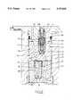
- FIG. 1is an axial cross sectional view of the pump
- FIG. 2is a cross sectional view on an enlarged scale of part of the pump which is seen in FIG. 1.
- the pumpcomprises a generally tubular body 10 and located against an annular step 11 in the body is a complementary step defined by a flanged portion of a pump barrel 12.
- a pump barrel 12Surrounding the flanged portion of the barrel is an annular chamber 13 which communicates with a fuel inlet (not shown) formed in the pump body.
- the chamberis also provided with anti-erosion baffles.
- Within the barrelthere is formed a bore 14 and slidable within the bore is a pumping plunger 15.
- the plungerextends from the bore and is provided with a head 16 with which is engaged a spring abutment 17.
- abutment 17Engaged with the abutment 17 is one end of a coiled compression spring 18 the opposite end of which abuts against a shim 19 which is interposed between the spring and a further step defined in the body.
- the interior surface of the body in the region of the spring abutmentis machined to form a bearing surface for a cup shaped tappet 20 which engages with the head 16 of the plunger.
- the tappetis retained within the body in known manner, by means of a circlip and in use, is urged inwardly by an engine driven cam.
- the plungeris shown in its outermost position and in this position the end of the plunger remote from the head uncovers a pair of inlet ports 21 which communicate at their outer ends, with the annular space 13. The ports 21 are covered during the initial inward movement of the plunger.
- valve blocks 22, 23,which are located in end to end relationship with the first valve block 22 being in engagement with the end surface of the pump barrel.
- the first block 22is held in sealing engagement with the adjacent end face of the pump barrel and with the adjacent face of the second valve block 23 by means of a mounting block 24 which has a portion located within the body 10 and defining an end surface for sealing engagement with the adjacent end surface of the valve block 23.
- the mounting blockis secured by means of bolts 25 to the body 10 and the action of tightening the bolts produces a clamping force which provides the required liquid seal between the adjacent contacting surfaces of the mounting block, the valve blocks and the pump barrel.
- the mounting block and the valve blockscan be secured together by screws to facilitate assembly.
- the first valve block 22houses a spill valve generally indicated at 26 and this takes the form of a valve member 27 slidable axially within a drilling 28 extending inwardly from the end face of the valve block which is engaged by the valve block 23. At its inner end the drilling defines a seating 29 about a spill passage 30 which communicates with the adjacent end of the bore 14.
- the valve member at its end adjacent the seatingis of reduced diameter so as to define an annular space 31 which communicates with the chamber 13 by way of a passage formed in the valve block and which is a continuation of the spill passage 30.
- the end of the valve memberis shaped to cooperate with the seating.
- an axial passage 32which terminates in a restriction through which the passage communicates with the spill passage 30.
- the opening of the passageis flared so as to afford permanent communication with a passage 34 which is formed in the valve block 23.
- the passage 34communicates with a further passage 35 formed in the mounting block 24 and which opens onto the end surface of a peripherally screw threaded spigot 36 machined on the mounting block.
- the spigotcarries a sleeve 37 into which is screwed the body of an electromagnetically operable valve 38.
- the valveis such that when electric current is supplied to the solenoid thereof, the passage 35 is closed and when the solenoid is de-energized, the passage is connected to a fuel drain.
- a passage 39which forms part of a fuel delivery channel which terminates in an outlet 40 formed on the mounting block 24.
- the outlet 40in use, is connected to a fuel injection nozzle of the associated engine.
- a delivery valveLocated in the fuel delivery channel is a delivery valve generally indicated at 41 in FIG. 1 and which is shown on a substantially enlarged scale in FIG. 2.
- the delivery valvecomprises a valve element 43 which is provided with longitudinal flutes on its external surface whereby the valve element is guided in a bore 44 formed in the valve block 23.
- the valve elementis biased into engagement with a seating 45 by means of a coiled compression spring 46 which conveniently is housed within a chamber 47 formed in the mounting block 24.
- the valve element 43is of hollow cup shaped form and formed in the base thereof is an opening 48 through which the interior of the valve member is in permanent communication with a passage 49 upstream of the seating 45, the passage 49 communicating with the passage 39 in the valve block 22.
- valve housing 50in which is formed a drilling 51 at the inner end of which is a seating for a spring loaded valve 52, the valve 52 being fluted.
- the valve housing 50may be in screw thread engagement with the valve element 43 and it forms an abutment for the spring 46.
- the opposite end of the spring 46engages a step defined on a stop member 50A which is located in the chamber 47 and which serves to limit the extent of movement as will be described, of the valve element 43.
- the stop memberdefines a central passage having in addition side entries 53, this passage forming part of the fuel delivery channel.
- valve 38If the valve 38 is energized the flow of fuel through the passage 32 will be prevented and this will cause a build up of pressure in the end portion of the cylinder 28 remote from the seating 29.
- the build up of pressurein view of the fact that there will be a pressure difference between the fuel in the spill passage 30 and the fuel in the chamber 13, will result in the valve member 27 moving into engagement with the seating 29 and when this occurs further flow of fuel through the spill passage 30 is prevented.
- the fueltherefore must flow through the fuel delivery channel towards the fuel injection nozzle. The result will be that the valve element 43 of the delivery valve will be lifted from its seating to permit such flow and this flow will continue so long as the plunger is being moved inwardly by the cam and the spill valve is in the closed position.
- the electromagnetically operable valve 38If while the plunger is moving inwardly, the electromagnetically operable valve 38 is de-energized, the fuel pressure at the end of the cylinder 28 connected to the valve 38 will fall and the high pressure within the bore will cause the spill valve to be lifted from its seating to allow fuel to spill from the bore along the spill passage 30. The reduction in pressure will permit the valve member in the fuel injection nozzle to close and also will allow the delivery valve element 43 to move into engagement with the seating 45.
- a reverse flow of fuel from the pipeline which connects the pump with the nozzlemay occur, such reverse flow being controlled by the valve 52 which can be set so that a predetermined pressure is maintained in the pipeline, the pressure being less than the pressure required to open the valve member of the nozzle.
- closure of the electromagnetic valve 38 whilst the plunger is moving inwardlydetermines the instant of fuel delivery to the associated engine and the length of time considered in terms of engine crankshaft rotation during which the valve is closed, determines the amount of fuel which is supplied to the engine.
- a light spring 54is provided to bias the valve member 27 of the spill valve to the open position.
- the delivery valve 41is a pressure unloading valve.
- the collarmay be a close sliding fit with the wall of the bore 44 in which case it will be exposed beyond the end of the bore when the delivery valve is in the fully open position.
- the collarmay however have a clearance with the bore in which case it may not be moved beyond the end of the bore.
- the axes of the bores 28 and 44 which house the spill valve, and the delivery valve respectively,are offset from the axis of the bore 14.
- the machining of the bores 28, 44is facilitated by the fact that the end portions of the valve blocks remote from the open ends of the bores are of cylindrical form and have their axes coinciding with the longitudinal axes of the respective bores.
- the pumpis mounted on the engine by means of a pair of mounting lugs integrally formed with the lower end of the pump body 10 at a position so that the tappet 20 can be engaged conveniently by a member which is driven by an engine driven cam.
- the systemincludes a fuel injection nozzle (not shown).
- the nozzleis a conventional nozzle having an inwardly opening valve member housed within a nozzle body, the valve member being biased by means of a spring to the closed position and being moved to the open position by means of fuel under pressure delivered by the pump.
- the nozzle bodyis mounted at the end of a holder which defines a chamber housing the spring which biases the valve member.
- An intermediate piecemay be located between the nozzle body and the end of the holder and a cap nut of conventional construction is utilized to retain the nozzle body relative to the holder.
- the supply of electric current to the solenoids of the valves 38is effected by means of a drive unit (not shown).
- the drive unitincludes a power pack which ensures that the solenoids will be energized from a constant voltage source and a switching unit which includes semiconductor drive elements connected in series with the solenoids respectively.
- the flow of current in the drive elementsis controlled so that the initial flow of current rises at a high rate to a value which may be maintained by a switching action and is then reduced to a lower value to hold the valves in the closed position. Provision is made to monitor the current flowing in the solenoids and also to check the operation of the valves.
- the period of time required for the valves 38 to move to the closed position or what can be regarded as the closed position together with the subsequent operation of the associated spill valves and other factors such as the time taken for the pressure wave to reach the injector,constitute a real time delay which must be taken into account when injection of fuel is required at a particular point in the engine operating cycle.
- the delay in terms of degrees of engine crankshaft rotationvaries with the engine speed but in addition the delay can vary with for example temperature.
- Mapsare provided in the drive unit so that the delay can be determined, the maps containing data obtained as a result of engine testing.
- the drive unitis supplied with an engine rotational position signal, an engine speed signal, a fuel demand signal and a timing demand signal and from these signals together with data extracted from the maps, a micro-processor in the drive unit can determine the exact instant at which the current should be supplied to the solenoids and the period of energization in order to secure injection of fuel at the correct instant in the engine operating cycle and in the required quantity.
- a micro-processor in the drive unitcan determine the exact instant at which the current should be supplied to the solenoids and the period of energization in order to secure injection of fuel at the correct instant in the engine operating cycle and in the required quantity.
- the solenoidsare energised in turn although for engines having a large number of cylinders two solenoids may be energized at the same time.
- the fuel demand signal and the timing demand signalare provided by a microprocessor based engine governor unit.
- the governor unitreceives a power/speed requirement signal from a high level control system and is provided with a number of maps containing data obtained as a result of engine testing. Such data for example, may relate to engine exhaust emissions and specific fuel consumption at different speeds and loads.
- the governor unitalso receives an engine speed signal together with signals relative to other engine operating parameters such for example as engine temperature and air inlet manifold pressure and on the basis of the signals obtained from the engine and the data contained in the maps, the fuel demand signal and the timing demand signal to the drive unit are determined.
- a typical application for an engine incorporating the fuel systemoccurs in a power generation, marine propulsion or rail traction system.
- a high level controllerwhich on the basis of operator demand and other inputs determines the power/speed requirement signal which is supplied to the governor unit.
- the governor unitcan also be used to monitor the performance of the engine and both the governor unit and the drive unit will include facilities for checking their operation and the operation of system sensors.
Landscapes
- Engineering & Computer Science (AREA)
- Chemical & Material Sciences (AREA)
- Combustion & Propulsion (AREA)
- Mechanical Engineering (AREA)
- General Engineering & Computer Science (AREA)
- Fuel-Injection Apparatus (AREA)
Abstract
Description
Claims (10)
Priority Applications (5)
| Application Number | Priority Date | Filing Date | Title |
|---|---|---|---|
| US07/944,789US5373828A (en) | 1992-09-11 | 1992-09-15 | Fuel injection system |
| GB9317903AGB2270545B (en) | 1992-09-11 | 1993-08-27 | Fuel injection system |
| DE4329142ADE4329142A1 (en) | 1992-09-11 | 1993-08-30 | Fuel injection system |
| IT93MI001866AIT1276343B1 (en) | 1992-09-11 | 1993-08-31 | FUEL INJECTION SYSTEM |
| JP5240282AJPH0791345A (en) | 1992-09-11 | 1993-09-02 | Fuel injection device |
Applications Claiming Priority (2)
| Application Number | Priority Date | Filing Date | Title |
|---|---|---|---|
| GB929219217AGB9219217D0 (en) | 1992-09-11 | 1992-09-11 | Fuel injection system |
| US07/944,789US5373828A (en) | 1992-09-11 | 1992-09-15 | Fuel injection system |
Publications (1)
| Publication Number | Publication Date |
|---|---|
| US5373828Atrue US5373828A (en) | 1994-12-20 |
Family
ID=26301597
Family Applications (1)
| Application Number | Title | Priority Date | Filing Date |
|---|---|---|---|
| US07/944,789Expired - Fee RelatedUS5373828A (en) | 1992-09-11 | 1992-09-15 | Fuel injection system |
Country Status (4)
| Country | Link |
|---|---|
| US (1) | US5373828A (en) |
| JP (1) | JPH0791345A (en) |
| DE (1) | DE4329142A1 (en) |
| IT (1) | IT1276343B1 (en) |
Cited By (15)
| Publication number | Priority date | Publication date | Assignee | Title |
|---|---|---|---|---|
| US5443049A (en)* | 1992-02-19 | 1995-08-22 | Lucas Industries Public Limited Company | Fuel pumping apparatus |
| US5517973A (en)* | 1993-03-30 | 1996-05-21 | Lucas Industries Public Limited Company | Fuel pump |
| WO1997012145A1 (en)* | 1995-09-12 | 1997-04-03 | Diesel Technology Company | Fuel injection pump having a solenoid operated control valve |
| US5954487A (en)* | 1995-06-23 | 1999-09-21 | Diesel Technology Company | Fuel pump control valve assembly |
| US5961052A (en)* | 1997-09-25 | 1999-10-05 | Caterpillar Inc. | Control valve having a top mounted single pole solenoid for a fuel injector |
| US5979415A (en)* | 1997-11-12 | 1999-11-09 | Caterpillar Inc. | Fuel injection pump with a hydraulically-spill valve |
| US6089470A (en)* | 1999-03-10 | 2000-07-18 | Diesel Technology Company | Control valve assembly for pumps and injectors |
| US6158419A (en)* | 1999-03-10 | 2000-12-12 | Diesel Technology Company | Control valve assembly for pumps and injectors |
| US6386185B1 (en)* | 1999-09-28 | 2002-05-14 | Delphi Technologies, Inc. | Valve arrangement |
| US6450778B1 (en) | 2000-12-07 | 2002-09-17 | Diesel Technology Company | Pump system with high pressure restriction |
| KR100470102B1 (en)* | 2001-06-18 | 2005-02-05 | 맨 비 앤드 더블유 디젤 에이/에스 | Device for supplying the fuel for internal combustion engine |
| US20140202422A1 (en)* | 2011-08-23 | 2014-07-24 | International Engine Intellectual Property Company, Llc | Controlling cylinder usage during reduced load on an internal combustion propulsion engine |
| GB2553484A (en)* | 2016-04-26 | 2018-03-14 | Delphi Int Operations Luxembourg Sarl | High pressure diesel pump |
| US20180135580A1 (en)* | 2015-06-10 | 2018-05-17 | Denso Corporation | High-pressure pump |
| US11352965B2 (en)* | 2019-10-18 | 2022-06-07 | Caterpillar Inc. | Reverse flow detection system |
Families Citing this family (1)
| Publication number | Priority date | Publication date | Assignee | Title |
|---|---|---|---|---|
| DE10062966A1 (en)* | 2000-12-16 | 2002-07-18 | Bosch Gmbh Robert | Single cylinder pump module for a fuel injection system of an internal combustion engine |
Citations (9)
| Publication number | Priority date | Publication date | Assignee | Title |
|---|---|---|---|---|
| DE2348865A1 (en)* | 1973-09-28 | 1975-04-10 | Maschf Augsburg Nuernberg Ag | Fuel injector system for compression ignition engines - has pressure relief valve fitted inside pump delivery valve to relieve pressure oscillations |
| US4129256A (en)* | 1977-09-12 | 1978-12-12 | General Motors Corporation | Electromagnetic unit fuel injector |
| US4422424A (en)* | 1981-06-23 | 1983-12-27 | The Bendix Corporation | Electronically controlled fuel injection pump |
| US4531672A (en)* | 1983-05-13 | 1985-07-30 | Cummins Engine Company, Inc. | Solenoid operated unit injector having distinct timing, metering and injection periods |
| US4653448A (en)* | 1984-02-22 | 1987-03-31 | Nippondenso Co., Ltd. | Fuel injection device |
| US4653455A (en)* | 1984-09-14 | 1987-03-31 | Robert Bosch Gmbh | Electrically controlled fuel injection pump for internal combustion engines |
| US4969600A (en)* | 1988-12-02 | 1990-11-13 | Lucas Industries | Fuel injection nozzle |
| US4997345A (en)* | 1988-09-02 | 1991-03-05 | Volkswagen Ag | Pressure relief valve for a fuel injection pump of an internal combustion engine |
| US5076241A (en)* | 1988-09-21 | 1991-12-31 | Toyota Jidosha Kabushiki Kaisha | Fuel injection device |
- 1992
- 1992-09-15USUS07/944,789patent/US5373828A/ennot_activeExpired - Fee Related
- 1993
- 1993-08-30DEDE4329142Apatent/DE4329142A1/ennot_activeWithdrawn
- 1993-08-31ITIT93MI001866Apatent/IT1276343B1/enactiveIP Right Grant
- 1993-09-02JPJP5240282Apatent/JPH0791345A/enactivePending
Patent Citations (9)
| Publication number | Priority date | Publication date | Assignee | Title |
|---|---|---|---|---|
| DE2348865A1 (en)* | 1973-09-28 | 1975-04-10 | Maschf Augsburg Nuernberg Ag | Fuel injector system for compression ignition engines - has pressure relief valve fitted inside pump delivery valve to relieve pressure oscillations |
| US4129256A (en)* | 1977-09-12 | 1978-12-12 | General Motors Corporation | Electromagnetic unit fuel injector |
| US4422424A (en)* | 1981-06-23 | 1983-12-27 | The Bendix Corporation | Electronically controlled fuel injection pump |
| US4531672A (en)* | 1983-05-13 | 1985-07-30 | Cummins Engine Company, Inc. | Solenoid operated unit injector having distinct timing, metering and injection periods |
| US4653448A (en)* | 1984-02-22 | 1987-03-31 | Nippondenso Co., Ltd. | Fuel injection device |
| US4653455A (en)* | 1984-09-14 | 1987-03-31 | Robert Bosch Gmbh | Electrically controlled fuel injection pump for internal combustion engines |
| US4997345A (en)* | 1988-09-02 | 1991-03-05 | Volkswagen Ag | Pressure relief valve for a fuel injection pump of an internal combustion engine |
| US5076241A (en)* | 1988-09-21 | 1991-12-31 | Toyota Jidosha Kabushiki Kaisha | Fuel injection device |
| US4969600A (en)* | 1988-12-02 | 1990-11-13 | Lucas Industries | Fuel injection nozzle |
Cited By (22)
| Publication number | Priority date | Publication date | Assignee | Title |
|---|---|---|---|---|
| US5443049A (en)* | 1992-02-19 | 1995-08-22 | Lucas Industries Public Limited Company | Fuel pumping apparatus |
| US5517973A (en)* | 1993-03-30 | 1996-05-21 | Lucas Industries Public Limited Company | Fuel pump |
| US5954487A (en)* | 1995-06-23 | 1999-09-21 | Diesel Technology Company | Fuel pump control valve assembly |
| US6059545A (en)* | 1995-06-23 | 2000-05-09 | Diesel Technology Company | Fuel pump control valve assembly |
| WO1997012145A1 (en)* | 1995-09-12 | 1997-04-03 | Diesel Technology Company | Fuel injection pump having a solenoid operated control valve |
| US5749717A (en)* | 1995-09-12 | 1998-05-12 | Deisel Technology Company | Electromagnetic fuel pump for a common rail fuel injection system |
| US5961052A (en)* | 1997-09-25 | 1999-10-05 | Caterpillar Inc. | Control valve having a top mounted single pole solenoid for a fuel injector |
| US5979415A (en)* | 1997-11-12 | 1999-11-09 | Caterpillar Inc. | Fuel injection pump with a hydraulically-spill valve |
| US6089470A (en)* | 1999-03-10 | 2000-07-18 | Diesel Technology Company | Control valve assembly for pumps and injectors |
| US6158419A (en)* | 1999-03-10 | 2000-12-12 | Diesel Technology Company | Control valve assembly for pumps and injectors |
| US6386185B1 (en)* | 1999-09-28 | 2002-05-14 | Delphi Technologies, Inc. | Valve arrangement |
| US6450778B1 (en) | 2000-12-07 | 2002-09-17 | Diesel Technology Company | Pump system with high pressure restriction |
| US20040076530A1 (en)* | 2000-12-07 | 2004-04-22 | Spoolstra Gregg R. | Pump system with high pressure restriction |
| US6854962B2 (en)* | 2000-12-07 | 2005-02-15 | Robert Bosch Gmbh | Pump system with high pressure restriction |
| KR100470102B1 (en)* | 2001-06-18 | 2005-02-05 | 맨 비 앤드 더블유 디젤 에이/에스 | Device for supplying the fuel for internal combustion engine |
| US20140202422A1 (en)* | 2011-08-23 | 2014-07-24 | International Engine Intellectual Property Company, Llc | Controlling cylinder usage during reduced load on an internal combustion propulsion engine |
| US20180135580A1 (en)* | 2015-06-10 | 2018-05-17 | Denso Corporation | High-pressure pump |
| US10527017B2 (en)* | 2015-06-10 | 2020-01-07 | Denso Corporation | High-pressure pump |
| US10907599B2 (en) | 2015-06-10 | 2021-02-02 | Denso Corporation | High-pressure pump |
| GB2553484A (en)* | 2016-04-26 | 2018-03-14 | Delphi Int Operations Luxembourg Sarl | High pressure diesel pump |
| US10995718B2 (en) | 2016-04-26 | 2021-05-04 | Delphi Technologies Ip Limited | High pressure diesel pump |
| US11352965B2 (en)* | 2019-10-18 | 2022-06-07 | Caterpillar Inc. | Reverse flow detection system |
Also Published As
| Publication number | Publication date |
|---|---|
| ITMI931866A1 (en) | 1995-03-03 |
| DE4329142A1 (en) | 1994-03-17 |
| IT1276343B1 (en) | 1997-10-30 |
| ITMI931866A0 (en) | 1993-08-31 |
| JPH0791345A (en) | 1995-04-04 |
Similar Documents
| Publication | Publication Date | Title |
|---|---|---|
| US5373828A (en) | Fuel injection system | |
| US4798186A (en) | Fuel injector unit | |
| EP0315328B1 (en) | Pneumatic direct cylinder fuel injection system | |
| US5150688A (en) | Magnet valve, in particular for fuel injection pumps | |
| US5740782A (en) | Positive-displacement-metering, electro-hydraulic fuel injection system | |
| US4957085A (en) | Fuel injection system for internal combustion engines | |
| US5785021A (en) | Hydraulically actuated electronic fuel injection system | |
| US5048497A (en) | Fuel injection unit | |
| US4567872A (en) | Unit fuel injector and system therefor | |
| DE59903599D1 (en) | FUEL INJECTION VALVE FOR INTERNAL COMBUSTION ENGINES | |
| US4394856A (en) | Compression operated injector with fuel injection control | |
| US5183019A (en) | Idling control device for high pressure fuel injection engine | |
| US5150684A (en) | High pressure fuel injection unit for engine | |
| US5115786A (en) | Fuel injection control system | |
| EP0736686B1 (en) | Fuel injection pump control | |
| JPS6113740Y2 (en) | ||
| US4969442A (en) | High pressure fuel injection device for engine | |
| US4745903A (en) | Pressure regulating valve | |
| US5345903A (en) | Engine stop control device | |
| GB2270545A (en) | Fuel injection system. | |
| US5655502A (en) | Injection timing control device for fuel injection pump | |
| US5081975A (en) | Idle stabilizing system for engine | |
| JP2598579B2 (en) | Fuel injection valve for internal combustion engine | |
| US5517973A (en) | Fuel pump | |
| EP0821154B1 (en) | Fuel pumping apparatus |
Legal Events
| Date | Code | Title | Description |
|---|---|---|---|
| AS | Assignment | Owner name:LUCAS INDUSTRIES PUBLIC LIMITED COMPANY, UNITED K Free format text:ASSIGNMENT OF ASSIGNORS INTEREST.;ASSIGNORS:ASKEW, JAMES M. A;JONES, ALAN G.;REEL/FRAME:006398/0407 Effective date:19921029 | |
| AS | Assignment | Owner name:LUCAS INDUSTRIES PUBLIC LIMITED COMPANY, UNITED KI Free format text:ASSIGNMENT OF ASSIGNORS INTEREST.;ASSIGNORS:LILLEY, ANDREW JOHN;VRANAS, GOULIELMOS;REEL/FRAME:006414/0822 Effective date:19921029 | |
| AS | Assignment | Owner name:LUCAS INDUSTRIES PUBLIC LIMITED COMPANY, UNITED KI Free format text:ASSIGNMENT OF ASSIGNORS INTEREST;ASSIGNORS:ASKEW, JAMES MARTIN ANDERTON;JONES, ALAN GRANVILLE;LILLEY, ANDREW J.;AND OTHERS;REEL/FRAME:006605/0201 Effective date:19921029 | |
| FEPP | Fee payment procedure | Free format text:PAYOR NUMBER ASSIGNED (ORIGINAL EVENT CODE: ASPN); ENTITY STATUS OF PATENT OWNER: LARGE ENTITY | |
| FPAY | Fee payment | Year of fee payment:4 | |
| AS | Assignment | Owner name:DELPHI TECHNOLOGIES, INC., MICHIGAN Free format text:ASSIGNMENT OF ASSIGNORS INTEREST;ASSIGNORS:LUCAS LIMITED;LUCAS INDUSTRIES LIMITED;REEL/FRAME:011742/0367 Effective date:20010409 | |
| REMI | Maintenance fee reminder mailed | ||
| LAPS | Lapse for failure to pay maintenance fees | ||
| LAPS | Lapse for failure to pay maintenance fees | Free format text:PATENT EXPIRED FOR FAILURE TO PAY MAINTENANCE FEES (ORIGINAL EVENT CODE: EXP.); ENTITY STATUS OF PATENT OWNER: LARGE ENTITY | |
| STCH | Information on status: patent discontinuation | Free format text:PATENT EXPIRED DUE TO NONPAYMENT OF MAINTENANCE FEES UNDER 37 CFR 1.362 | |
| FP | Lapsed due to failure to pay maintenance fee | Effective date:20021220 |