US5373809A - Pet cage doors with raised central sections - Google Patents
Pet cage doors with raised central sectionsDownload PDFInfo
- Publication number
- US5373809A US5373809AUS08/224,505US22450594AUS5373809AUS 5373809 AUS5373809 AUS 5373809AUS 22450594 AUS22450594 AUS 22450594AUS 5373809 AUS5373809 AUS 5373809A
- Authority
- US
- United States
- Prior art keywords
- door
- opening
- cage
- wire
- central portion
- Prior art date
- Legal status (The legal status is an assumption and is not a legal conclusion. Google has not performed a legal analysis and makes no representation as to the accuracy of the status listed.)
- Expired - Fee Related
Links
- 230000002093peripheral effectEffects0.000claimsabstractdescription16
- 241001465754MetazoaSpecies0.000claimsabstractdescription14
- 230000001154acute effectEffects0.000claimsdescription3
- 238000010276constructionMethods0.000description5
- 230000007246mechanismEffects0.000description4
- 238000000034methodMethods0.000description3
- 230000008878couplingEffects0.000description2
- 238000010168coupling processMethods0.000description2
- 238000005859coupling reactionMethods0.000description2
- 239000000463materialSubstances0.000description2
- 238000012986modificationMethods0.000description2
- 230000004048modificationEffects0.000description2
- 229910000831SteelInorganic materials0.000description1
- 230000002596correlated effectEffects0.000description1
- 238000003780insertionMethods0.000description1
- 230000037431insertionEffects0.000description1
- 238000007689inspectionMethods0.000description1
- 238000004519manufacturing processMethods0.000description1
- 239000010959steelSubstances0.000description1
- 230000000153supplemental effectEffects0.000description1
Images

Classifications
- A—HUMAN NECESSITIES
- A01—AGRICULTURE; FORESTRY; ANIMAL HUSBANDRY; HUNTING; TRAPPING; FISHING
- A01K—ANIMAL HUSBANDRY; AVICULTURE; APICULTURE; PISCICULTURE; FISHING; REARING OR BREEDING ANIMALS, NOT OTHERWISE PROVIDED FOR; NEW BREEDS OF ANIMALS
- A01K1/00—Housing animals; Equipment therefor
- A01K1/02—Pigsties; Dog-kennels; Rabbit-hutches or the like
- A01K1/035—Devices for use in keeping domestic animals, e.g. fittings in housings or dog beds
- A—HUMAN NECESSITIES
- A01—AGRICULTURE; FORESTRY; ANIMAL HUSBANDRY; HUNTING; TRAPPING; FISHING
- A01K—ANIMAL HUSBANDRY; AVICULTURE; APICULTURE; PISCICULTURE; FISHING; REARING OR BREEDING ANIMALS, NOT OTHERWISE PROVIDED FOR; NEW BREEDS OF ANIMALS
- A01K31/00—Housing birds
- A01K31/10—Doors; Trap-doors
Definitions
- the present inventionrelates to pet cage doors with raised central sections and more particularly pertains to closing an aperture in an animal cage through a door having an offset, high-profile central section.
- pet cages and doorsThe use of pet cages and doors is known in the prior art. More specifically, pet cages and doors heretofore devised and utilized for the purpose of securing animals within cages having doors are known to consist basically of familiar, expected, and obvious structural configurations, notwithstanding the myriad of designs encompassed by the crowded prior art which has been developed for the fulfillment of countless objectives and requirements.
- the new and improved pet cage door with offset planar sectionsubstantially departs from the conventional concepts and designs of the prior art, and in doing so provides an apparatus primarily developed for the purpose of closing an aperture in an animal cage through a door having an offset, high-profile central section.
- the present inventionprovides new and improved pet cage doors with raised central sections.
- the general purpose of the present inventionwhich will be described subsequently in greater detail, is to provide new and improved pet cage doors with raised central sections and methods which have all the advantages of the prior art and none of the disadvantages.
- the present inventionessentially comprises a new and improved pet cage door with a raised central section comprising, in combination, a rectangular screen formed of a plurality of spaced horizontal and vertical wires coupled in a mesh-like configuration and constituting a door, the door being positionable over the front screen of an animal cage formed with a rectangular opening of a predetermined height and width, the door being formed of horizontal and vertical wires with a height and width greater than the height and width of the opening; the rectangular screen having a raised central portion and peripheral regions formed vertically and horizontally as extensions of the central portion, the peripheral portions being beveled at an acute angle with respect to the central portion and terminating in horizontal and vertical end wires adapted to contact the front screen of the cage when the door is in a closed orientation; a plurality of wire loops encompassing an endmost vertical wire of the door and an adjacent vertical wire of the cage front screen to constitute a hinge for opening and closing the door, at least one of the loops adapted to be located between a vertical wire of the door and cage front screen to pre
- An even further object of the present inventionis to provide new and improved pet cage doors with raised central sections which are susceptible of a low cost of manufacture with regard to both materials and labor, and which accordingly are then susceptible of low prices of sale to the consuming public, thereby making such new and improved pet cage doors with raised central sections economically available to the buying public.
- Still yet another object of the present inventionis to provide new and improved pet cage doors with raised central sections which provide in the apparatuses and methods of the prior art some of the advantages thereof, while simultaneously overcoming some of the disadvantages normally associated therewith.
- Even still another object of the present inventionis to close an aperture in an animal cage through a door having an offset, high-profile central section.
- a pet cage door with raised central sectioncomprising a rectangular screen formed of a plurality of spaced horizontal and vertical wires coupled in a mesh-like configuration and constituting a door, the door being positionable over the front screen of an animal cage formed with a rectangular opening of a predetermined height and width, the door being formed of horizontal and vertical wires with a height and width greater than the height and width of the opening; the rectangular screen having a raised central portion and peripheral regions formed vertically and horizontally as extensions of the central portion, the peripheral portions being beveled at an angle with respect to the central portion and terminating in horizontal and vertical end wires adapted to contact the front screen of the cage when the door is in a closed orientation; a plurality of wire loops encompassing an endmost wire of the door and an adjacent wire of the cage front screen to constitute a hinge for opening and closing the door, at least one of the loops adapted to be located between an endmost wire of the door and cage front screen to preclude excess shifting of the door with respect to
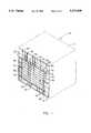
- FIG. 1is a perspective illustration of an animal cage illustrating the preferred embodiment of the new and improved pet cage door with offset planar section constructed in accordance with the principles of the present invention.
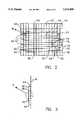
- FIG. 2is a front elevational view of the door and cage front illustrated in FIG. 1.
- FIG. 3is an enlarged end view of the locking mechanism for the door illustrated in FIGS. 1 and 2.
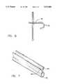
- FIG. 4is an enlarged showing of the hinge area coupling the door and cage front taken at the circle 4 of FIG. 2.
- FIG. 5is an enlarged showing of the locking mechanism for the door taken at circle 5 of FIG. 3.
- FIG. 6is an end view of the locking mechanism illustrated in FIG. 5.
- FIG. 7is a perspective illustration of a plastic door guard located on each side of the doorway of the cage shown in FIGS. 1 and 2.
- FIGS. 1 through 7the preferred embodiment of the new and improved pet cage door with offset planar section embodying the principles and concepts of the present invention and generally designated by the reference numeral 10 will be described.
- the present inventionis constructed of a plurality of separate components.
- such componentsinclude the cage with a screen front and rectangular opening therein, a rectangular screen functioning as a door, the raised central portion of the screen with beveled sides, wired loops for functioning as hinges, a semi-rigid wire formed as a locking member, and plastic door guards around the opening in the cage front.
- Such componentsare specifically configured and correlated one with respect to the other in order to obtain the desired objectives.
- the pet cage 12is of a generally conventional construction. It has parallel top and bottom walls, parallel side walls and parallel front and rear walls coupled together at their edges to form a box-like container.
- the front wall 14is of a mesh configuration with horizontal and vertical wires 16 and 18.
- a rectangular opening 20is formed in the center thereof with a peripheral upper and lower wire 22 and 24 and peripheral edge wires 26 and 28.
- a rectangular screen 32Located in association with the cage front is a rectangular screen 32.
- the screenis formed of a plurality of spaced horizontal and vertical wires 34 and 36 coupled in a mesh-like configuration and constituting a door 38.
- the dooris positionable over the front opening screen of the cage.
- the doorhas a height and width which are both greater than the height and width of the opening in the cage front.
- the rectangular screenhas a raised rectangular central portion 42 and peripheral regions formed vertically and horizontally as extensions of the central portion.
- the peripheral regionsinclude a top portion 44, a bottom portion 46, an interior lateral portion 48 and an exterior lateral portion 50.
- the peripheral portionsare all beveled at an acute angle with respect to the central portion.
- Each peripheral portionterminates in a wire, horizontal wires 52 and 54 above and below and vertical wires 56 and 58 interiorly and exteriorly at the vertical edges.
- Such end wiresare adapted to contact the front screen of the cage upwardly of the opening when the door is in a closed orientation.
- a plurality of wire loops 62are formed to encompass the endmost vertical wire of the door and an adjacent vertical wire of the cage proximate to the vertical edge wire of the opening.
- Such wire loopsconstitute a hinge 64 for opening and closing the door.
- At least one of the loops, preferably the top loop 66,is adapted to be located between a vertical wire of the door and an adjacent vertical wire of the cage.
- This particular loopfunctions to preclude excess vertical shifting or dropping of the door with respect to the opening. As such, it insures that when closed the door does not fall an excessive amount to cause an inadvertent passage along the upper horizontal extent of the opening.
- the locking member 70is formed from a semi-rigid wire having a loop 72 at its central extent.
- the locking memberis secured to the wires of the door by supplemental wire loops 74.
- the couplingis adjacent to the vertical edge of the door remote from the hinge.
- the loophas a horizontal extension 76 extending horizontally to a location outboardly of the door and opening.
- the loopextends inwardly and is formed with a curve 78 adapted to be releasably moved by a user to encompass a central horizontal wire of the cage front for locking the door with respect to the opening.
- the wiremay be pushed inwardly and lifted whereby the curve will clear its associated wire to allow opening of the door.
- the last component of the systemis in the nature of a plurality of plastic door guards 82.
- Such guardsare of a generally C-shaped configuration and are positionable over the wires around the opening of the door.
- the outermost ends 84 of the guardsare flared outwardly to allow ease of insertion of the guards into position on the cage opening.
- Such guardspromote safety whereby the user may insert hands and arms into the cage or out of the cage and also to allow passage of a pet through the opening when the door is open.
- the present inventionis a product that enhances and improves both small and large animal pet cages. Conventional pet cages are made with flat doors. The present invention improves on this design in virtue of the fact that it is a "high profile" door with beveled edges. This new design is not only more attractive, but it is also stronger, safer and fits better over the plastic door guards on each side of the doorway.
- Both the cage to which it is attached and the present invention itselfare made of steel mesh.
- Each end of the doorangles out away from the cage slightly, after which it bends again, this time by the same degree in the opposite direction, into a parallel position with the front surface of the cage. This is what gives the door a beveled look.
- This attributereadily offers a means for the end user to differentiate between a contemporary cage with a conventional door, and one of better quality.
Landscapes
- Life Sciences & Earth Sciences (AREA)
- Environmental Sciences (AREA)
- Zoology (AREA)
- Animal Husbandry (AREA)
- Biodiversity & Conservation Biology (AREA)
- Birds (AREA)
- Animal Behavior & Ethology (AREA)
- Housing For Livestock And Birds (AREA)
Abstract
Description
Claims (3)
Priority Applications (1)
| Application Number | Priority Date | Filing Date | Title |
|---|---|---|---|
| US08/224,505US5373809A (en) | 1994-04-07 | 1994-04-07 | Pet cage doors with raised central sections |
Applications Claiming Priority (1)
| Application Number | Priority Date | Filing Date | Title |
|---|---|---|---|
| US08/224,505US5373809A (en) | 1994-04-07 | 1994-04-07 | Pet cage doors with raised central sections |
Publications (1)
| Publication Number | Publication Date |
|---|---|
| US5373809Atrue US5373809A (en) | 1994-12-20 |
Family
ID=22840990
Family Applications (1)
| Application Number | Title | Priority Date | Filing Date |
|---|---|---|---|
| US08/224,505Expired - Fee RelatedUS5373809A (en) | 1994-04-07 | 1994-04-07 | Pet cage doors with raised central sections |
Country Status (1)
| Country | Link |
|---|---|
| US (1) | US5373809A (en) |
Cited By (16)
| Publication number | Priority date | Publication date | Assignee | Title |
|---|---|---|---|---|
| USD367734S (en) | 1994-06-01 | 1996-03-05 | Doskocil Mfg. Co. | Combined kennel door and latch |
| US6217677B1 (en) | 1999-06-28 | 2001-04-17 | Ford Global Technologies, Inc. | Method for annealing stamped components |
| US6312506B1 (en) | 1998-06-16 | 2001-11-06 | Telefonaktiebolaget Lm Ericsson (Publ) | Method for reducing moisture content within a housing by reducing thermal inertia on a side of the housing |
| US6408742B1 (en) | 1998-12-21 | 2002-06-25 | Alan L. Backus | Spit rod assembly for rotisserie oven |
| US6450087B2 (en) | 1998-12-21 | 2002-09-17 | Alan L. Backus | Rotisserie oven having a shaped food basket |
| US6568316B1 (en) | 2001-12-05 | 2003-05-27 | Alan L. Backus | Rotisserie spit attachment |
| US6658991B2 (en) | 1998-12-21 | 2003-12-09 | Alan L. Backus | Barbeque grill spit assembly |
| US6874408B2 (en) | 1998-12-21 | 2005-04-05 | Advantage Partners Ip, Llc | Rotisserie cooker |
| US7021203B2 (en) | 1998-12-21 | 2006-04-04 | Advantage Partners Llc | Vented countertop rotisserie oven |
| US7225730B2 (en) | 1998-12-21 | 2007-06-05 | Ronco Marketing Corporation | Spit assembly support base |
| US20080172947A1 (en)* | 2007-01-19 | 2008-07-24 | Matteson Michael L | Reversible door with integral pivot pin |
| US7514651B2 (en) | 2004-09-20 | 2009-04-07 | Ronco Acquisition Corporation | Rotisserie oven having horizontally and vertically oriented cooking elements |
| US7626142B2 (en) | 1998-12-21 | 2009-12-01 | Ronco Acquisition Corporation | Enclosed rotisserie with detachable electronic components |
| US7739948B2 (en) | 1997-07-07 | 2010-06-22 | Ronco Acquisition Corporation | Simplified device to quickly cook food |
| US7878111B2 (en) | 1998-12-21 | 2011-02-01 | Ronco Acquisition Corporation | Heating and venting arrangement for a rotisserie oven |
| CN106069797A (en)* | 2016-07-04 | 2016-11-09 | 黄立成 | A kind of control device of wire cage cage door |
Citations (8)
| Publication number | Priority date | Publication date | Assignee | Title |
|---|---|---|---|---|
| US1107871A (en)* | 1913-10-21 | 1914-08-18 | Homer R Alkire | Collapsible housing device. |
| US2822780A (en)* | 1956-11-02 | 1958-02-11 | William S Buell | Animal cage |
| US3058445A (en)* | 1959-08-13 | 1962-10-16 | Wallace M L Johnson | Collapsible wire mesh cage |
| US3490417A (en)* | 1967-07-31 | 1970-01-20 | Elaine P Swinney | Combination shipping and living compartment for animals |
| US4046107A (en)* | 1976-07-14 | 1977-09-06 | Kuster Herman A | Laying cage subfloor |
| US4781147A (en)* | 1987-08-14 | 1988-11-01 | Delino Jr Joseph V | Portable safety seat and carrier for small animal |
| US5010848A (en)* | 1989-10-23 | 1991-04-30 | Rankin William J | Folding travel cage |
| US5168829A (en)* | 1991-06-12 | 1992-12-08 | Dietrich Bruce E | Versa cage system |
- 1994
- 1994-04-07USUS08/224,505patent/US5373809A/ennot_activeExpired - Fee Related
Patent Citations (8)
| Publication number | Priority date | Publication date | Assignee | Title |
|---|---|---|---|---|
| US1107871A (en)* | 1913-10-21 | 1914-08-18 | Homer R Alkire | Collapsible housing device. |
| US2822780A (en)* | 1956-11-02 | 1958-02-11 | William S Buell | Animal cage |
| US3058445A (en)* | 1959-08-13 | 1962-10-16 | Wallace M L Johnson | Collapsible wire mesh cage |
| US3490417A (en)* | 1967-07-31 | 1970-01-20 | Elaine P Swinney | Combination shipping and living compartment for animals |
| US4046107A (en)* | 1976-07-14 | 1977-09-06 | Kuster Herman A | Laying cage subfloor |
| US4781147A (en)* | 1987-08-14 | 1988-11-01 | Delino Jr Joseph V | Portable safety seat and carrier for small animal |
| US5010848A (en)* | 1989-10-23 | 1991-04-30 | Rankin William J | Folding travel cage |
| US5168829A (en)* | 1991-06-12 | 1992-12-08 | Dietrich Bruce E | Versa cage system |
Cited By (26)
| Publication number | Priority date | Publication date | Assignee | Title |
|---|---|---|---|---|
| USD367734S (en) | 1994-06-01 | 1996-03-05 | Doskocil Mfg. Co. | Combined kennel door and latch |
| US7739948B2 (en) | 1997-07-07 | 2010-06-22 | Ronco Acquisition Corporation | Simplified device to quickly cook food |
| US6312506B1 (en) | 1998-06-16 | 2001-11-06 | Telefonaktiebolaget Lm Ericsson (Publ) | Method for reducing moisture content within a housing by reducing thermal inertia on a side of the housing |
| US6837150B2 (en) | 1998-12-21 | 2005-01-04 | Advantage Partners | Food cooking rotisserie |
| US7021203B2 (en) | 1998-12-21 | 2006-04-04 | Advantage Partners Llc | Vented countertop rotisserie oven |
| US6536334B2 (en) | 1998-12-21 | 2003-03-25 | Advantage Partners Ip, Llc | Spit assembly for rotisserie oven |
| US6568315B2 (en) | 1998-12-21 | 2003-05-27 | Alan L. Backus | Rotisserie and spit assembly |
| US8017167B2 (en) | 1998-12-21 | 2011-09-13 | Ronco Holding, Inc. | Food cooking basket for a rotisserie oven |
| US6658991B2 (en) | 1998-12-21 | 2003-12-09 | Alan L. Backus | Barbeque grill spit assembly |
| US6742445B2 (en) | 1998-12-21 | 2004-06-01 | Advantage Partners Ip, Llc | Horizontal rotisserie oven |
| US6782806B2 (en) | 1998-12-21 | 2004-08-31 | Advantage Partners Ip, Llc | Food cooking rotisserie |
| US6782805B2 (en) | 1998-12-21 | 2004-08-31 | Advantage Partners Ip, Llc | Food cooking rotisserie |
| US6408742B1 (en) | 1998-12-21 | 2002-06-25 | Alan L. Backus | Spit rod assembly for rotisserie oven |
| US6874408B2 (en) | 1998-12-21 | 2005-04-05 | Advantage Partners Ip, Llc | Rotisserie cooker |
| US6450087B2 (en) | 1998-12-21 | 2002-09-17 | Alan L. Backus | Rotisserie oven having a shaped food basket |
| US7225730B2 (en) | 1998-12-21 | 2007-06-05 | Ronco Marketing Corporation | Spit assembly support base |
| US7225729B2 (en) | 1998-12-21 | 2007-06-05 | Ronco Marketing Corporation | Countertop rotisserie oven with warming unit |
| US7878111B2 (en) | 1998-12-21 | 2011-02-01 | Ronco Acquisition Corporation | Heating and venting arrangement for a rotisserie oven |
| US7424849B2 (en) | 1998-12-21 | 2008-09-16 | Ronco Acquisition Corporation | Rotisserie cooker |
| US7626142B2 (en) | 1998-12-21 | 2009-12-01 | Ronco Acquisition Corporation | Enclosed rotisserie with detachable electronic components |
| US6217677B1 (en) | 1999-06-28 | 2001-04-17 | Ford Global Technologies, Inc. | Method for annealing stamped components |
| US6568316B1 (en) | 2001-12-05 | 2003-05-27 | Alan L. Backus | Rotisserie spit attachment |
| US7514651B2 (en) | 2004-09-20 | 2009-04-07 | Ronco Acquisition Corporation | Rotisserie oven having horizontally and vertically oriented cooking elements |
| US7805808B2 (en)* | 2007-01-19 | 2010-10-05 | Schroer Manufacturing Company | Reversible door with integral pivot pin |
| US20080172947A1 (en)* | 2007-01-19 | 2008-07-24 | Matteson Michael L | Reversible door with integral pivot pin |
| CN106069797A (en)* | 2016-07-04 | 2016-11-09 | 黄立成 | A kind of control device of wire cage cage door |
Similar Documents
| Publication | Publication Date | Title |
|---|---|---|
| US5373809A (en) | Pet cage doors with raised central sections | |
| US12035687B2 (en) | Animal crate with swing or drop door | |
| US11528883B2 (en) | Animal crate with swing or drop door assembly | |
| US10420319B2 (en) | Animal enclosure | |
| US5136803A (en) | Bait box | |
| US8925492B2 (en) | Collapsible wire crate and method of assembly | |
| US5040327A (en) | Polygonal bait station | |
| US6427631B1 (en) | Pet carrier | |
| US10716284B2 (en) | Pet door enclosure system | |
| US5167202A (en) | Window pet porch | |
| US7213368B1 (en) | Apparatus for vertical sliding pet door | |
| US20140150728A1 (en) | Door for household pet carrier | |
| CA3013890A1 (en) | Animal crate latch | |
| US20210144954A1 (en) | Animal crate with removably coupled divider panel assembly | |
| US4995336A (en) | Animal entrance | |
| US2792961A (en) | Tackle box | |
| US4104986A (en) | Bird cage with transparent shield | |
| US5634434A (en) | Self closing dog house door | |
| US6415844B1 (en) | Garage doorway screen apparatus | |
| US5852987A (en) | Pet food container shielding device | |
| CN209219011U (en) | Poison bait station | |
| US3068607A (en) | Minnow container and system | |
| US2683438A (en) | Multiple hen nest | |
| US2105879A (en) | Automatic door for turkey nests | |
| JP6479494B2 (en) | Cat cage |
Legal Events
| Date | Code | Title | Description |
|---|---|---|---|
| FEPP | Fee payment procedure | Free format text:PETITION RELATED TO MAINTENANCE FEES FILED (ORIGINAL EVENT CODE: PMFP); ENTITY STATUS OF PATENT OWNER: SMALL ENTITY | |
| FEPP | Fee payment procedure | Free format text:PETITION RELATED TO MAINTENANCE FEES GRANTED (ORIGINAL EVENT CODE: PMFG); ENTITY STATUS OF PATENT OWNER: SMALL ENTITY | |
| FP | Lapsed due to failure to pay maintenance fee | Effective date:19981220 | |
| FPAY | Fee payment | Year of fee payment:4 | |
| SULP | Surcharge for late payment | ||
| PRDP | Patent reinstated due to the acceptance of a late maintenance fee | Effective date:19990521 | |
| AS | Assignment | Owner name:DEBBIE J. BALDWIN, OHIO Free format text:ASSIGNMENT OF ASSIGNORS INTEREST;ASSIGNOR:SPHAR, FAYNE A.;REEL/FRAME:010133/0245 Effective date:19990719 | |
| AS | Assignment | Owner name:BALDWIN, ALBERT, OHIO Free format text:ASSIGNMENT OF ASSIGNORS INTEREST;ASSIGNOR:BALDWIN, DEBBIE J.;REEL/FRAME:012407/0742 Effective date:20010129 | |
| REMI | Maintenance fee reminder mailed | ||
| LAPS | Lapse for failure to pay maintenance fees | ||
| STCH | Information on status: patent discontinuation | Free format text:PATENT EXPIRED DUE TO NONPAYMENT OF MAINTENANCE FEES UNDER 37 CFR 1.362 | |
| FP | Lapsed due to failure to pay maintenance fee | Effective date:20021220 |