US5372587A - Steerable medical device - Google Patents
Steerable medical deviceDownload PDFInfo
- Publication number
- US5372587A US5372587AUS08/031,810US3181093AUS5372587AUS 5372587 AUS5372587 AUS 5372587AUS 3181093 AUS3181093 AUS 3181093AUS 5372587 AUS5372587 AUS 5372587A
- Authority
- US
- United States
- Prior art keywords
- wire
- steering
- deflection
- inches
- housing
- Prior art date
- Legal status (The legal status is an assumption and is not a legal conclusion. Google has not performed a legal analysis and makes no representation as to the accuracy of the status listed.)
- Expired - Lifetime
Links
- 238000006073displacement reactionMethods0.000claimsabstractdescription25
- 238000004804windingMethods0.000claimsdescription15
- 239000000835fiberSubstances0.000abstractdescription19
- 230000002262irrigationEffects0.000abstractdescription19
- 238000003973irrigationMethods0.000abstractdescription19
- 239000012530fluidSubstances0.000abstractdescription10
- 230000005540biological transmissionEffects0.000abstractdescription7
- 239000002775capsuleSubstances0.000abstractdescription5
- 238000012377drug deliveryMethods0.000abstractdescription2
- 239000000463materialSubstances0.000description30
- 238000000034methodMethods0.000description27
- 238000002399angioplastyMethods0.000description23
- 230000033001locomotionEffects0.000description22
- 229910052751metalInorganic materials0.000description22
- 239000002184metalSubstances0.000description22
- 230000007704transitionEffects0.000description21
- 230000006870functionEffects0.000description20
- 238000000576coating methodMethods0.000description19
- 239000011248coating agentSubstances0.000description17
- 229910001220stainless steelInorganic materials0.000description16
- 230000004323axial lengthEffects0.000description14
- 208000027418Wounds and injuryDiseases0.000description13
- 229910001000nickel titaniumInorganic materials0.000description13
- 238000005476solderingMethods0.000description12
- 239000010935stainless steelSubstances0.000description12
- 238000005219brazingMethods0.000description11
- HLXZNVUGXRDIFK-UHFFFAOYSA-Nnickel titaniumChemical compound[Ti].[Ti].[Ti].[Ti].[Ti].[Ti].[Ti].[Ti].[Ti].[Ti].[Ti].[Ni].[Ni].[Ni].[Ni].[Ni].[Ni].[Ni].[Ni].[Ni].[Ni].[Ni].[Ni].[Ni].[Ni]HLXZNVUGXRDIFK-UHFFFAOYSA-N0.000description11
- 239000000853adhesiveSubstances0.000description10
- 230000001070adhesive effectEffects0.000description10
- 238000001125extrusionMethods0.000description9
- BASFCYQUMIYNBI-UHFFFAOYSA-NplatinumChemical compound[Pt]BASFCYQUMIYNBI-UHFFFAOYSA-N0.000description9
- 239000004677NylonSubstances0.000description8
- 238000013461designMethods0.000description8
- 238000013147laser angioplastyMethods0.000description8
- 229920001778nylonPolymers0.000description8
- 239000004952PolyamideSubstances0.000description7
- 239000011324beadSubstances0.000description7
- 238000010276constructionMethods0.000description7
- 239000004035construction materialSubstances0.000description7
- 238000004519manufacturing processMethods0.000description7
- 229920002647polyamidePolymers0.000description7
- -1polyethylenePolymers0.000description7
- 239000004593EpoxySubstances0.000description6
- 210000001367arteryAnatomy0.000description6
- 230000001965increasing effectEffects0.000description6
- 230000003287optical effectEffects0.000description6
- 230000037361pathwayEffects0.000description6
- 229910000679solderInorganic materials0.000description6
- 230000008901benefitEffects0.000description5
- 230000006835compressionEffects0.000description5
- 238000007906compressionMethods0.000description5
- 238000007887coronary angioplastyMethods0.000description5
- 208000014674injuryDiseases0.000description5
- 229920000642polymerPolymers0.000description5
- 230000008569processEffects0.000description5
- 230000008733traumaEffects0.000description5
- 229910045601alloyInorganic materials0.000description4
- 239000000956alloySubstances0.000description4
- 238000007598dipping methodMethods0.000description4
- 230000002526effect on cardiovascular systemEffects0.000description4
- 229910000701elgiloys (Co-Cr-Ni Alloy)Inorganic materials0.000description4
- 238000003780insertionMethods0.000description4
- 230000037431insertionEffects0.000description4
- 150000002739metalsChemical class0.000description4
- 239000004033plasticSubstances0.000description4
- 229920003023plasticPolymers0.000description4
- 229910052697platinumInorganic materials0.000description4
- 230000004044responseEffects0.000description4
- 239000007787solidSubstances0.000description4
- 210000004026tunica intimaAnatomy0.000description4
- 238000012800visualizationMethods0.000description4
- 239000010963304 stainless steelSubstances0.000description3
- 239000004698PolyethyleneSubstances0.000description3
- 229910000589SAE 304 stainless steelInorganic materials0.000description3
- 238000005452bendingMethods0.000description3
- 210000004087corneaAnatomy0.000description3
- 210000004351coronary vesselAnatomy0.000description3
- 238000000227grindingMethods0.000description3
- 238000003801millingMethods0.000description3
- 210000000056organAnatomy0.000description3
- 229920000573polyethylenePolymers0.000description3
- 229920001296polysiloxanePolymers0.000description3
- 229920001343polytetrafluoroethylenePolymers0.000description3
- 239000004810polytetrafluoroethyleneSubstances0.000description3
- 238000000926separation methodMethods0.000description3
- 230000002966stenotic effectEffects0.000description3
- 210000001519tissueAnatomy0.000description3
- 230000002792vascularEffects0.000description3
- 238000003466weldingMethods0.000description3
- 208000002177CataractDiseases0.000description2
- JOYRKODLDBILNP-UHFFFAOYSA-NEthyl urethaneChemical compoundCCOC(N)=OJOYRKODLDBILNP-UHFFFAOYSA-N0.000description2
- 229910000639Spring steelInorganic materials0.000description2
- 208000007536ThrombosisDiseases0.000description2
- HZEWFHLRYVTOIW-UHFFFAOYSA-N[Ti].[Ni]Chemical compound[Ti].[Ni]HZEWFHLRYVTOIW-UHFFFAOYSA-N0.000description2
- 238000004026adhesive bondingMethods0.000description2
- 238000005520cutting processMethods0.000description2
- 238000005516engineering processMethods0.000description2
- 238000001727in vivoMethods0.000description2
- 230000007246mechanismEffects0.000description2
- 229910001092metal group alloyInorganic materials0.000description2
- 238000000465mouldingMethods0.000description2
- 230000009972noncorrosive effectEffects0.000description2
- 238000010422paintingMethods0.000description2
- 230000002093peripheral effectEffects0.000description2
- 229920000728polyesterPolymers0.000description2
- 230000009467reductionEffects0.000description2
- 125000006850spacer groupChemical group0.000description2
- 239000007921spraySubstances0.000description2
- 238000005507sprayingMethods0.000description2
- 239000000126substanceSubstances0.000description2
- 238000001356surgical procedureMethods0.000description2
- 238000012546transferMethods0.000description2
- 210000005166vasculatureAnatomy0.000description2
- 206010060965Arterial stenosisDiseases0.000description1
- 229910000906BronzeInorganic materials0.000description1
- 241001092081CarpenteriaSpecies0.000description1
- 229920001651CyanoacrylatePolymers0.000description1
- MWCLLHOVUTZFKS-UHFFFAOYSA-NMethyl cyanoacrylateChemical compoundCOC(=O)C(=C)C#NMWCLLHOVUTZFKS-UHFFFAOYSA-N0.000description1
- OAICVXFJPJFONN-UHFFFAOYSA-NPhosphorusChemical compound[P]OAICVXFJPJFONN-UHFFFAOYSA-N0.000description1
- 241000910050Sacothrips catheterSpecies0.000description1
- 239000004809TeflonSubstances0.000description1
- 229920006362Teflon®Polymers0.000description1
- 230000009471actionEffects0.000description1
- 230000002411adverseEffects0.000description1
- 238000004873anchoringMethods0.000description1
- 238000000137annealingMethods0.000description1
- 238000013459approachMethods0.000description1
- 210000001815ascending colonAnatomy0.000description1
- 229920000249biocompatible polymerPolymers0.000description1
- 238000001574biopsyMethods0.000description1
- 230000036760body temperatureEffects0.000description1
- 238000009954braidingMethods0.000description1
- 239000010974bronzeSubstances0.000description1
- 230000000747cardiac effectEffects0.000description1
- 210000000748cardiovascular systemAnatomy0.000description1
- 230000008859changeEffects0.000description1
- 238000005345coagulationMethods0.000description1
- 230000015271coagulationEffects0.000description1
- 238000004891communicationMethods0.000description1
- KUNSUQLRTQLHQQ-UHFFFAOYSA-Ncopper tinChemical compound[Cu].[Sn]KUNSUQLRTQLHQQ-UHFFFAOYSA-N0.000description1
- 238000005336crackingMethods0.000description1
- 238000002788crimpingMethods0.000description1
- 230000003247decreasing effectEffects0.000description1
- 230000010339dilationEffects0.000description1
- 238000005553drillingMethods0.000description1
- 230000002183duodenal effectEffects0.000description1
- 238000001839endoscopyMethods0.000description1
- 230000002708enhancing effectEffects0.000description1
- 229920006332epoxy adhesivePolymers0.000description1
- 230000001747exhibiting effectEffects0.000description1
- 210000001105femoral arteryAnatomy0.000description1
- 210000005224forefingerAnatomy0.000description1
- 239000012634fragmentSubstances0.000description1
- 239000007789gasSubstances0.000description1
- 230000002496gastric effectEffects0.000description1
- PCHJSUWPFVWCPO-UHFFFAOYSA-NgoldChemical compound[Au]PCHJSUWPFVWCPO-UHFFFAOYSA-N0.000description1
- 239000010931goldSubstances0.000description1
- 229910052737goldInorganic materials0.000description1
- 238000013007heat curingMethods0.000description1
- 238000005286illuminationMethods0.000description1
- 230000006872improvementEffects0.000description1
- 238000007373indentationMethods0.000description1
- 238000001802infusionMethods0.000description1
- 238000001746injection mouldingMethods0.000description1
- 230000001788irregularEffects0.000description1
- 230000003902lesionEffects0.000description1
- 229920001684low density polyethylenePolymers0.000description1
- 239000004702low-density polyethyleneSubstances0.000description1
- 239000003550markerSubstances0.000description1
- 238000002844meltingMethods0.000description1
- 230000008018meltingEffects0.000description1
- 239000012528membraneSubstances0.000description1
- 230000000399orthopedic effectEffects0.000description1
- 239000002245particleSubstances0.000description1
- 238000011160researchMethods0.000description1
- 238000007790scrapingMethods0.000description1
- 238000007789sealingMethods0.000description1
- 238000004904shorteningMethods0.000description1
- 239000002904solventSubstances0.000description1
- 229910052715tantalumInorganic materials0.000description1
- GUVRBAGPIYLISA-UHFFFAOYSA-Ntantalum atomChemical compound[Ta]GUVRBAGPIYLISA-UHFFFAOYSA-N0.000description1
- 230000001225therapeutic effectEffects0.000description1
- 229920001169thermoplasticPolymers0.000description1
- 239000004416thermosoftening plasticSubstances0.000description1
- 210000003813thumbAnatomy0.000description1
- 238000012549trainingMethods0.000description1
- WFKWXMTUELFFGS-UHFFFAOYSA-NtungstenChemical compound[W]WFKWXMTUELFFGS-UHFFFAOYSA-N0.000description1
- 229910052721tungstenInorganic materials0.000description1
- 239000010937tungstenSubstances0.000description1
- 238000004078waterproofingMethods0.000description1
Images


Classifications
- A—HUMAN NECESSITIES
- A61—MEDICAL OR VETERINARY SCIENCE; HYGIENE
- A61M—DEVICES FOR INTRODUCING MEDIA INTO, OR ONTO, THE BODY; DEVICES FOR TRANSDUCING BODY MEDIA OR FOR TAKING MEDIA FROM THE BODY; DEVICES FOR PRODUCING OR ENDING SLEEP OR STUPOR
- A61M25/00—Catheters; Hollow probes
- A61M25/01—Introducing, guiding, advancing, emplacing or holding catheters
- A61M25/0105—Steering means as part of the catheter or advancing means; Markers for positioning
- A61M25/0133—Tip steering devices
- A61M25/0147—Tip steering devices with movable mechanical means, e.g. pull wires
- A—HUMAN NECESSITIES
- A61—MEDICAL OR VETERINARY SCIENCE; HYGIENE
- A61M—DEVICES FOR INTRODUCING MEDIA INTO, OR ONTO, THE BODY; DEVICES FOR TRANSDUCING BODY MEDIA OR FOR TAKING MEDIA FROM THE BODY; DEVICES FOR PRODUCING OR ENDING SLEEP OR STUPOR
- A61M25/00—Catheters; Hollow probes
- A61M25/0043—Catheters; Hollow probes characterised by structural features
- A61M25/005—Catheters; Hollow probes characterised by structural features with embedded materials for reinforcement, e.g. wires, coils, braids
- A61M25/0053—Catheters; Hollow probes characterised by structural features with embedded materials for reinforcement, e.g. wires, coils, braids having a variable stiffness along the longitudinal axis, e.g. by varying the pitch of the coil or braid
- A—HUMAN NECESSITIES
- A61—MEDICAL OR VETERINARY SCIENCE; HYGIENE
- A61M—DEVICES FOR INTRODUCING MEDIA INTO, OR ONTO, THE BODY; DEVICES FOR TRANSDUCING BODY MEDIA OR FOR TAKING MEDIA FROM THE BODY; DEVICES FOR PRODUCING OR ENDING SLEEP OR STUPOR
- A61M25/00—Catheters; Hollow probes
- A61M25/01—Introducing, guiding, advancing, emplacing or holding catheters
- A61M25/0105—Steering means as part of the catheter or advancing means; Markers for positioning
- A61M25/0133—Tip steering devices
- A61M25/0144—Tip steering devices having flexible regions as a result of inner reinforcement means, e.g. struts or rods
- A—HUMAN NECESSITIES
- A61—MEDICAL OR VETERINARY SCIENCE; HYGIENE
- A61M—DEVICES FOR INTRODUCING MEDIA INTO, OR ONTO, THE BODY; DEVICES FOR TRANSDUCING BODY MEDIA OR FOR TAKING MEDIA FROM THE BODY; DEVICES FOR PRODUCING OR ENDING SLEEP OR STUPOR
- A61M25/00—Catheters; Hollow probes
- A61M25/01—Introducing, guiding, advancing, emplacing or holding catheters
- A61M25/06—Body-piercing guide needles or the like
- A61M25/0662—Guide tubes
- A—HUMAN NECESSITIES
- A61—MEDICAL OR VETERINARY SCIENCE; HYGIENE
- A61B—DIAGNOSIS; SURGERY; IDENTIFICATION
- A61B17/00—Surgical instruments, devices or methods
- A61B17/22—Implements for squeezing-off ulcers or the like on inner organs of the body; Implements for scraping-out cavities of body organs, e.g. bones; for invasive removal or destruction of calculus using mechanical vibrations; for removing obstructions in blood vessels, not otherwise provided for
- A61B2017/22072—Implements for squeezing-off ulcers or the like on inner organs of the body; Implements for scraping-out cavities of body organs, e.g. bones; for invasive removal or destruction of calculus using mechanical vibrations; for removing obstructions in blood vessels, not otherwise provided for with an instrument channel, e.g. for replacing one instrument by the other
- A—HUMAN NECESSITIES
- A61—MEDICAL OR VETERINARY SCIENCE; HYGIENE
- A61M—DEVICES FOR INTRODUCING MEDIA INTO, OR ONTO, THE BODY; DEVICES FOR TRANSDUCING BODY MEDIA OR FOR TAKING MEDIA FROM THE BODY; DEVICES FOR PRODUCING OR ENDING SLEEP OR STUPOR
- A61M25/00—Catheters; Hollow probes
- A61M25/01—Introducing, guiding, advancing, emplacing or holding catheters
- A61M25/0105—Steering means as part of the catheter or advancing means; Markers for positioning
- A61M25/0133—Tip steering devices
- A61M25/0147—Tip steering devices with movable mechanical means, e.g. pull wires
- A61M2025/015—Details of the distal fixation of the movable mechanical means
- A—HUMAN NECESSITIES
- A61—MEDICAL OR VETERINARY SCIENCE; HYGIENE
- A61M—DEVICES FOR INTRODUCING MEDIA INTO, OR ONTO, THE BODY; DEVICES FOR TRANSDUCING BODY MEDIA OR FOR TAKING MEDIA FROM THE BODY; DEVICES FOR PRODUCING OR ENDING SLEEP OR STUPOR
- A61M25/00—Catheters; Hollow probes
- A61M25/01—Introducing, guiding, advancing, emplacing or holding catheters
- A61M25/0105—Steering means as part of the catheter or advancing means; Markers for positioning
- A61M25/0133—Tip steering devices
- A61M25/0138—Tip steering devices having flexible regions as a result of weakened outer material, e.g. slots, slits, cuts, joints or coils
- A—HUMAN NECESSITIES
- A61—MEDICAL OR VETERINARY SCIENCE; HYGIENE
- A61M—DEVICES FOR INTRODUCING MEDIA INTO, OR ONTO, THE BODY; DEVICES FOR TRANSDUCING BODY MEDIA OR FOR TAKING MEDIA FROM THE BODY; DEVICES FOR PRODUCING OR ENDING SLEEP OR STUPOR
- A61M25/00—Catheters; Hollow probes
- A61M25/01—Introducing, guiding, advancing, emplacing or holding catheters
- A61M25/09—Guide wires
- A61M25/09016—Guide wires with mandrils
- A61M25/09025—Guide wires with mandrils with sliding mandrils
- A—HUMAN NECESSITIES
- A61—MEDICAL OR VETERINARY SCIENCE; HYGIENE
- A61M—DEVICES FOR INTRODUCING MEDIA INTO, OR ONTO, THE BODY; DEVICES FOR TRANSDUCING BODY MEDIA OR FOR TAKING MEDIA FROM THE BODY; DEVICES FOR PRODUCING OR ENDING SLEEP OR STUPOR
- A61M3/00—Medical syringes, e.g. enemata; Irrigators
- A61M3/02—Enemata; Irrigators
- A61M3/0279—Cannula; Nozzles; Tips; their connection means
Definitions
- the present inventionrelates to steering devices such as may be used with catheters, cannulae, guidewires and the like. More particularly, the present invention relates to catheters and guidewires that are steerable through body lumen or cavities and positionable within or aimable at obstructions, organs or tissue within the body from a position external to the body.
- Medical cathetersgenerally comprise elongate tube-like members which may be inserted into the body, either percutaneously or via a body orifice, for any of a wide variety of diagnostic and therapeutic purposes. Such medical applications frequently require use of a catheter having the ability to negotiate twists and turns, particularly with regard to certain cardiovascular applications.
- Percutaneous Transluminal Coronary AngioplastyBalloon angioplasty
- Balloon angioplastyrequires manipulation of a catheter from a position outside the patient's body through extended portions of the patient's arterial system to the stenotic site for the purpose of alleviating the obstruction by inflating a balloon. This particular procedure has been performed with increasing frequency over the past years in preference to open heart bypass surgery, when possible.
- a guidewireis transluminally inserted into the brachial or the femoral artery, to be positioned within the stenotic region and followed by a balloon catheter.
- the cardiologistusually pre-bends the distal tip of the guidewire before insertion and then rotates (or torques) the wire once it has reached a branch artery to enable the guidewire to enter the branch. If the angle of the bend has to be adjusted, the guidewire must be removed, re-bent and reinserted, sometimes several times. Particular difficulty is encountered with prebending where an artery branches at one angle, and then sub-branches at a different angle. This procedure is attended by the risk of significant trauma to the arterial lining, and, in many cases, the obstruction cannot be reached at all with the guidewire and catheter.
- Coronary arteriesare tortuous, have many sub-branches and often the obstruction is either located where the diameter of the artery is small or, by its very presence, the obstruction leaves only a very small opening through which a guidewire and/or catheter can be passed. Consequently, the cardiologist often finds it very difficult to maneuver the guidewire or catheter, which are typically several feet long, from the proximal end.
- Transluminal Laser Catheter AngioplastyIn another application, Transluminal Laser Catheter Angioplasty (laser angioplasty), the delivery of laser energy from an external source to an intraluminal site to remove plaque or thrombus obstructions in vessels is accomplished by providing a waveguide such as a fiber optic bundle within a catheter.
- a waveguidesuch as a fiber optic bundle within a catheter.
- laser angioplastyrequires an even greater ability to precisely manipulate the catheter, to control and aim the laser light at the specific plaques or thrombi to be removed.
- U.S. Pat. No. 3,470,876 to Barchilondiscloses a catheter device having a central lumen extending therethrough, and four tensioning cords extending along an inner wall of the catheter.
- the '876 patentspecifically recites that catheters may be produced in accordance with the Barchilon design having diameters of 0,125 to 2 inches, and are suited for applications such as within the duodenal bulb or ascending colon. These diameters are unsuited for use as a guidewire in coronary angioplasty, which typically requires diameters in the area of as small as from about 0.014 to 0.018 inches.
- the steering deviceis constructed in a manner which permits a diameter as small as that of existing dilatation catheters or guidewires used in angioplasty applications.
- the steering deviceadditionally permits controlled lateral deflection of the distal tip.
- a steerable sheathfor steering or aiming within a body cavity, such as an organ or a body lumen.
- the sheathcomprises an elongate flexible tubular housing, having proximal and distal ends and at least one central passageway extending axially therethrough.
- a deflection elementis secured to the housing at a first point, and extends axially along the housing.
- a pull elementis secured to the housing at a second point and extends axially along the housing. The second point is rotationally displaced from the first point, preferably by at least about 90°, and, more preferably, by about 180°.
- Axial proximal displacement of the pull elementcauses a lateral displacement of a portion of the tubular housing disposed distally of the first point.
- a steerable sheath of the typehaving an elongate flexible tubular body with a deflectable distal end and a high central lumen to outside diameter ratio.
- the sheathcomprises a tubular housing, and a deflection element secured to the housing and extending in an axial direction.
- a pull elementis provided, extending axially through the housing, and secured with respect to the distal end of the housing. Axial displacement of the pull element laterally displaces the distal tip of the housing.
- the diameter of the central lumen extending through the housingis at least about 65% of the outer diameter of the housing. More preferably, the diameter of the central lumen is at least about 75% of the outer diameter of the housing, and, in one embodiment, the diameter of the central lumen is at least about 80% of the outer diameter of the housing.
- an irrigation and aspiration toolcomprising a tubular body, having a deflactable distal region, and a pull wire extending proximally from a distal end of the tubular body.
- a first tubular sleeveis provided on at least the deflectable region of the tubular body. Proximal axial displacement of the pull wire causes a lateral deflection of the deflectable end of the tubular body.
- the tubular bodycomprises a spring coil.
- the first tubular sleevesurrounds the exterior of the spring coil.
- a second tubular sleeveis spaced radially outwardly from the spring coil to provide and annular flow passage, such as for irrigation of a preselected site.
- a steerable sheath of the typehaving an elongate flexible tubular body and a deflectable distal end.
- the sheathcomprises a tubular housing, having a deflection element secured therein and extending axially therethrough.
- a pull elementextends axially through the housing, and is secured with respect to the distal end thereof.
- an outer polymeric jacketis provided in tight sealing contact with the housing, for improving the pushability of the housing and optimizing torque transmission throughout the housing.
- FIG. 1is a partial sectional perspective view of a steerable guidewire according to the present invention, with the outer tubular casing removed.
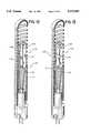
- FIG. 2is an elevational sectional view of the guidewire of FIG. 1, illustrated in a first deflected position.
- FIG. 3is an elevational sectional view of the guidewire of FIG. 1, illustrated in a second deflected position.
- FIG. 4is a partial sectional perspective view of a steerable laser angioplasty catheter according to the present invention.
- FIG. 5is a further embodiment of the steerable guidewire of the present invention.
- FIG. 6is a schematic view of the guidewire of FIG. 1, illustrated as negotiating an arterial branch point and approaching an arterial stenosis.
- FIG. 7is an elevational perspective view of a further embodiment of a steering device according to the present invention.
- FIG. 8is an elevational perspective view of still a further embodiment of the present invention.
- FIG. 9is a cross-sectional view along the line 9--9 of the device of FIG. 8.
- FIG. 10is a simplified front elevational view of the device shown in FIG. 8, following application of an anchor cap.
- FIG. 11is a simplified front elevational view of the device shown in FIG. 7, following application of an anchor cap.
- FIG. 12is a partial sectional perspective view of a "ribbon" steering device according to the present invention, with the outer tubular casing removed.
- FIG. 13is an elevational perspective view of a another embodiment of a "ribbon" steering device according to the present invention.
- FIG. 14is a side-elevational view of a guidewire incorporating a single deflection wire embodiment of the steering device in accordance with the present invention.
- FIG. 15is an enlargement of a distal portion of the guidewire illustrated in FIG. 14.
- FIGS. 16, 17 and 18show an enlarged view of the guidewire illustrated in FIG. 15.
- FIG. 19is a side-elevational view of the region marked 19 in FIG. 14.
- FIG. 20is an elevational cross-sectional view through the lines 20--20 in FIG. 19.
- FIG. 21is an elevational cross-sectional view taken along the lines 21--21 in FIG. 15.
- FIG. 22illustrates a helical channel in the distal end of a hypotube segment, adapted to receive a spring coil.
- FIG. 23illustrates one embodiment of a central core wire or deflection wire in accordance with one aspect of the present invention.
- FIG. 24is a cross-sectional view of the distal end of a steerable sheath in accordance with a further aspect of the present invention.
- FIG. 25is a cross-sectional view through lines 25--25 of FIG. 24.
- FIG. 26is a cross-sectional view of the steerable sheath of FIG. 24, shown in a deflected configuration.
- FIG. 27is a cross-sectional view of the distal end of a steerable aspiration device in accordance with a further aspect of the present invention.
- FIG. 28is a cross-sectional view along lines 28--28 in FIG. 27.
- an elongate flexible implement 10having a tubular body 11 with a proximal end 12 and a distal end 14.
- the distal end 14comprises a steering region 16, and the proximal end 12 is provided with a control 18 for steering the implement 10, which may be, for example, a steerable guidewire or catheter.
- a control 18 for steering the implement 10which may be, for example, a steerable guidewire or catheter.
- the steering device of the present inventionwill generally be described herein as incorporated into an angioplasty guidewire, it is to be understood that one skilled in the art will be able to readily adapt the steering device to other medical and non-medical applications.
- the body 11 of steerable implement 10may be any desired length from inches to many feet depending upon the intended application. In an embodiment useful as an angioplasty guidewire or catheter, the body 11 will typically be several feet long, and will preferably be about 135-180 cm, as is typical of existing angioplasty catheters and guidewires respectively. However, any suitable length may be used. Typically, the proximal most 120 to 150 cm of the body 11 is hypotube, as is well known in the art, and the distal 30 cm comprises a metal coil.
- the body 11may be constructed in any of a variety of ways known in the art, such as by tightly winding a coil of metal wire, or extrusion of a relatively flexible biocompatible polymer such as polyethylene.
- Wound guidewirespreferably comprise a high tensile strength wire of a resilient, non-corrosive metal such as stainless steel or platinum, and may have a circular cross section with a diameter of from about 0.001 to 0.020 in.
- the wiremay alternatively have a rectangular cross section of from about 0.001 to 0.020 inches by from about 0.001 to 0.040 inches, or other variations known in the art.
- Construction materials and techniques for manufacturing wire wound guidewiresare well known in the art, and a typical 180 cm teflon coated 0.014 inch or 0.016 inch diameter non-steerable guidewire may be obtained from U.S. Catheter, Inc., a division of C.R. Bard, Inc., located in Billerica, Mass., U.S.A.
- the external diameter of wire wound guidewireswill of course be a function of the intended application.
- the wire wound coronary angioplasty guidewires incorporating the steering device of the present inventionare preferably wound to have an external diameter in the range of from about 0.014 inches to about 0.018 inches.
- the diameter of the cathetercan be varied to optimize the diameter of a central working channel as desired, while still maintaining a sufficiently small exterior diameter for the intended application.
- Steerable balloon angioplasty catheters incorporating the present inventionwill typically have an exterior diameter in the range of from about 0.020 inches to about 0.041 inches or larger as permitted by location of the lesion.
- the exterior surface of the wound coil type guidewire shaft 10is provided with an elastic, biocompatible coating or sheath to provide a smooth outer surface.
- Suitable coatingscan be formed by dipping, spraying or wrapping and heat curing operations as are known in the art.
- heat shrinkable tubingcan provide a suitable outer sheath.
- a coating materialshould be selected which will permit sufficient flexing of the body 11 without cracking, will minimize sliding friction of the implement 10 during insertion and removal, and is substantially chemically inert in the in vivo vascular environment.
- suitable materialsare known, including, for example, polytetrafluoroethylene, urethane or polyethylene.
- the body 11 of flexible implement 10typically terminates at its distal end 14 in a closed tip 20.
- the tip 20is formed by a rounded braze or solder joint, which may also serve to secure the distal ends of the deflection wires.
- the deflection wirescan extend distally beyond their point of attachment to the ribbon or post, to function as a safety wire, or a separate safety wire may be secured at one end to the inside of the tip 20, and at the other end to the post 22 or support 24.
- the tip 20is constructed of a resilient polymeric material such as silicone or urethane which will minimize trauma to the vascular intima, as will be appreciated by one of skill in the art.
- Steering region 16Disposed intermediate the tip 20 and body 11 of a flexible implement 10 in accordance with the present invention is a floppy but controllable steering region 16.
- Steering region 16is constructed in a manner that facilitates lateral displacement of the tip 20 relative to the axis of the body 11, through physical design and/or choice of flexible construction materials.
- the revolutions of wire per unit of axial distance along the bodyis reduced in the steering region 16 relative to body 11 to provide a looser wound coil having space 17 between adjacent wire loops, as illustrated in FIGS. 1-6.
- lateral deflection of steering region 16 to the leftmay involve both an axial compression of adjacent wire loops on the inside surface 36 of the bend, and an axial separation of the adjacent wire loops on the outside surface 38 of the bend.
- the steering region 16may be made from a variety of suitable metal or plastic coils or flexible sleeves. Materials opaque to X-rays, such as platinum, gold, tungsten, tantalum or the like, may be advantageously incorporated therein, to act as a fluoroscopic marker to aid in visualization.
- a steering post 22is provided, extending in a generally axial direction within the steering region 16 of flexible body 11.
- the steering post 22is disposed coaxially within the central lumen of steering region 16 when the steering region 16 and body 11 are linearly aligned, such as when at rest. See FIG. 1.
- the steering post 22is secured in the steering region 16 in a manner that substantially prevents axial displacement thereof yet permits lateral deflection of the axis of the steering post 22 away from the axis of body 11.
- Post 22preferably comprises a resilient shaft which may be molded or extruded from any of a variety of materials, such as nylon, and may have a cross-sectional dimension of from about 0.002 inches up to about 0.012 inches for use in a typical steerable angioplasty guidewire embodiment.
- a variety of resilient or springy metals in the form of wirecan also be used to form post 22, such as phosphor bronze, spring steel, Nitinol, or other resilient metal.
- the length of steering post 22will, of course, be dependant upon the length of the steering region 16.
- the entire steering region 16will be on the order of from about 0.040 to about 1.0 inches and preferably from about 0.120 to about 0.150 inches long, and the steering post 22 may be from one-quarter to two-thirds that length.
- steering post 22may extend distally all the way to the distal tip 20 of the steerable implement 10, it is preferred to limit the length to the proximal one-half or one-third of the axial length of steering region 16 to minimize rigidity in the steering region 16 yet permit sufficient steerability thereof.
- the distal end 27 of steering post 22will be spaced apart from the interior surface of tip 20 by a distance of from about one-tenth to one-half an inch or more, thus permitting the steering region 16 of the catheter shaft to be as floppy as desired.
- the distal portion of a fiber optics bundle or flexible tube for defining a working channeladditionally functions as the steering post 22, the post 22 will extend all the way to the distal tip 20 and be exposed to the outside by way of an opening therethrough. See, for example, FIG. 4.
- steering post 22is further provided with a bead or enlarged region 26 to optimize transmission of lateral force from the steering post 22 to the wall of steering region 16.
- bead 26is most effectively located at or near the distal end of steering post 22.
- Bead 26may be formed by dipping or coating techniques, or may be a preformed member having an opening therein for sliding over the end of steering post 22.
- post 22can be molded or milled to provide a bead 26 integrally formed thereon.
- Bead 26is preferably substantially circular in a cross section perpendicular to the axis of post 22, and the external diameter of the bead 26 is only slightly less than the interior diameter of the steering region 16 so that maximum lateral motion of the steering post 22 is transmitted to the steering region 16, but bead 26 also remains only in slidable contact with the interior surface thereof.
- the proximal end 23 of the steering post 22is mounted to or in pivotable contact with a radial support 24, in a manner which permits pivoting of the steering post 22 throughout a full 360° range of motion about the axis of body 11.
- the postmay also be molded or milled as an integral part of disk 24.
- the support 24comprises any means by which the deflection wires 28 are displaced radially outwardly from the axis of the tubular body 11, such as by the thickness of the post 22 or other structure including the plate embodiment illustrated in FIGS. 1-3.
- the support 24 of the illustrated embodimentcomprises a circular disk 25 located within the tubular body 11 of the steerable implement 10, preferably located near the distal end thereof.
- the disk 25is axially secured within the tubular body 11 to provide a stationary radial support for at least one deflection wire 28, and pivotable mount for steering post 22.
- Disk 25may be attached, for example, by friction fit between adjacent turns of coiled spring wire.
- Steering post 22preferably is attached to or in contact with the disk 25 in a manner which permits it to swivel from 90 degrees to close to 0 degrees, relative to the lateral plane of disk 25.
- the disk 25may be made of stainless steel or any of a variety of other suitable materials such as other metals or plastic polymers which will provide a sufficiently axially rigid seat for the proximal end 23 of steering post 22.
- Disk 25may be formed by stamping from sheet stock and drilling, injection molding, or other techniques well known in the art. Preferably, a central depression or orifice is provided thereon, for providing an axial seat for steering post 22.
- the diameter of disk 25can vary, however, it will typically be no greater than, but may approximate the outside diameter of the steerable implement 10. Diameters from about 0.14 to 0.050 inches may preferably be used in the construction of cardiac angioplasty catheters.
- Lateral deflection of the steering post 22 away from the axis of body 11is accomplished by proximal axial displacement of any of a plurality of deflection wires 28 extending proximally throughout the length of flexible body 11.
- a plurality of deflection wires 28extending proximally throughout the length of flexible body 11.
- three or four deflection wires 28are employed in the "post" embodiment to provide a full 360° range of motion of the steering region 16 about the axis of the body 11, as will become apparent. Only a single deflection wire 28 will be described in detail herein.
- deflection wire 28is secured such as by adhesives (or brazing or soldering, etc.) to the steering post 22 at the distal end thereof, or at a variety of other locations along the length of post 22.
- adhesivesor brazing or soldering, etc.
- the deflection wire 28is mechanically linked to the post 22 but need not necessarily be directly secured thereto.
- the deflection wire 28could be secured to an annular flange or ring surrounding the post or other structure which may be convenient from a manufacturing standpoint to provide a sufficiently secure linkage to accomplish the intended steering function.
- an eye on the end of the deflection wirecan surround the post 22 and rest against a stop formed by a milled shoulder or adhesive, or other means of attachment as will be apparent to one of skill in the art.
- the deflection wire 28preferably extends radially outwardly from the point of attachment to the steering post 22 to the support 24.
- the support 24is preferably provided with a notch or orifice 40 for each deflection wire 28 to extend through, said orifice 40 spaced radially outwardly from the axis of the tubular body 11 by a first distance.
- the distal end of each deflection wire 28is secured to the steering post 22 at a point radially displaced from the axis of the steering post 22 by a second distance, and the first distance is preferably greater than the second distance to maximize the lateral component of force.
- the second distancepreferably approaches zero; however, it will inherently include the radius of the steering post 22 where the deflection wire 28 is secured intermediate the two ends thereof.
- each orifice 40is separated from each adjacent orifice by an angle of approximately 120°.
- the deflection wiresmay be made of stainless steel, nylon or any other suitable material which provides sufficient tensile strength and flexibility.
- the deflection wiresare braided from multiple strands, as is detailed below.
- the diameter of the wirescan range from 0.001 to 0.005 inches or more, and suitability of particular sizes or materials can be readily determined by experimentation.
- control 18 for steering the catheteris shown schematically in FIGS. 1-3.
- the control device 18is preferably provided at its center with a pivotable mount 32 to permit it to be tipped throughout a full 360° range of motion.
- control 18comprises a circular plate 34 secured to proximal end 12 of flexible shaft 10 by way of pivotable mount 32.
- Deflection wires 28are spaced equally radially outwardly from the pivotable center of the control device and at equal angular distances around the plate 34.
- Deflecting plate 34 from a plane normal to the axis of shaft 10transmits force via one or more deflection wires 28, a component of which is resolved into a lateral force to deflect the catheter tip toward or away from the longitudinal axis of catheter. Selective tipping of the deflection plate 34 results in rotation of the catheter tip to any desired orientation.
- any control devicecan be envisioned for use with the steerable implement of the present invention.
- a "joy stick" type devicecomprising a single lever which can be displaced to any position throughout a nearly hemispherical range of motion might be used.
- a portion of the proximal end 12 of tubular body 11is enlarged to a cross section of a half inch or larger to facilitate grip.
- the enlarged sectionis provided with a plurality of axially slidable switches, one corresponding to each deflection wire 28. Manipulation of the switches by the thumb or forefinger will obtain the desired deflection of steering region 16.
- any control devicewill preferably be provided with a stop to prevent bending of the post 22 or steering region 16 past its elastic limit.
- support 24is typically within one or two inches, and preferably less than one inch, from the distal tip 20 of an angioplasty catheter or guidewire embodiment of the invention.
- a fulcrum 44is provided at a point intermediate the radial support 24 and point of attachment 42 for maintaining the deflection wire 28 concave in a radial inward direction.
- the fulcrum 44may conveniently comprise a substantially radially symmetrical member such as a sphere or toroid, which can also function to limit proximal axial movement of steering post 22 through a central opening in support 24.
- the point of attachment of deflection wires 28may be to the fulcrum 44 instead of directly to the steering post 22.
- a steerable medical implementfor use in percutaneous transluminal laser angioplasty applications.
- an elongate flexible implement 45comprising at its distal end a floppy steering region 46.
- enhanced flexibilitymay be imparted to steering region 46 by providing spacing 47 between adjacent loops of wound wire 48.
- a radial support means 49is disposed at the proximal end of steering region 46, which may comprise a circular plate 50 or other structure for displacing deflection wires 52 radially outwardly from the axis of implement 45.
- a waveguide such as a fiber optic bundle 54extends the entire length of the implement 45, for directing laser light from a source (not illustrated) disposed at the proximal end of the implement 45, to a point of application within a coronary artery at the distal tip 56 of the implement 45.
- the optical pathway 54extends throughout the length of steering region 46 and traverses tip 56 by way of an opening 58 therein.
- Each of the deflection wires 52is secured at its distal end to the fiber optic bundle 54 at a point intermediate radial support 49 and distal tip 56.
- the point of attachment of deflection wires 52 to the fiber optic bundle 54is less than half the distance and preferably is within one-third of the distance between the radial support 49 and distal tip 56, in order to optimize the lateral component of force.
- a laser angioplasty catheter incorporating the present inventionpermits the controlled direction of a beam of light transmitted through fiber bundle 54 at any desired point within a full 360° circle on a plane normal to the axis of the implement 45.
- a waveguidesuch as fiber bundle 54.
- substantially parallel but discrete bundles of fiber opticscan be secured adjacent one another within the fiber bundle 54 to permit a plurality of discrete light transmitting channels.
- a plurality of concentric optical pathwayscan be provided as is well known in the art.
- a plurality of discrete optical pathwaysmay advantageously be used to perform a variety of functions.
- a first optical pathwaymight be utilized to permit visualization of the stenotic site or other surface to be treated.
- a separate optical pathwaymay be utilized to transmit light for illuminating the site.
- a third optical pathwaymight be utilized to transmit the laser light.
- an aspiration ductmay be provided near the distal end of the implement 45, for suctioning debris or gases which may be generated as a result of the action of the laser.
- a flexible tubemay be incorporated into the steering device of the present invention, thereby providing a working channel to receive additional implements therethrough.
- FIG. 7there is disclosed a further embodiment of the steering device in accordance with the present invention.
- the steerable device illustrated in FIG. 7can be incorporated into a guidewire, or directly into a catheter, such as a balloon dilation catheter, or other elongate implement for which steerability is desired. It is to be understood that while certain preferred dimensions and construction materials will be recited in the discussion of the present embodiment, these illustrate a single angioplasty guidewire embodiment only and in no way limit the scope of the present invention.
- the steering device 60preferably is incorporated into a steerable guidewire, of the type made from an elongate flexible hypotube and tubular spring coil 61 having a central lumen extending therethrough.
- the spring coil 61may be further provided with an outer sheath or coating, as are known in the art, or the spring coil may, by itself, serve as the outer wall of the guidewire.
- the proximal end of the spring coil 61is made up of a plurality of adjacent loops of wire, which may in turn be connected to a solid walled tube such as a length of hypodermic needle stock.
- a 150 cm length of hypotubehaving a nominal 0.0135 inch outside diameter and 0.007 inch inside diameter will be used for this purpose.
- Lateral flexibility of the spring coil 61 at a distal steering regioncan be enhanced by providing a spacing between adjacent loops of the spring coil. These features are illustrated in FIGS. 1-6 of a previous embodiment of the present invention, and need no further discussion here.
- the adjacent loops of wire in the steering regioncan be in contact with one another, i.e., no axial spacing, when the steering region is in an orientation co-linear with the axis of the adjacent guidewire.
- Post 62Extending axially within the steering region of the spring coil 61 is a central post 62.
- Post 62is preferably made from a flexible polymeric extrusion, or from a metal or metal alloy such as Nitinol, although any of a wide variety of materials can be incorporated into the post 62 of the present invention.
- the post 62comprises a nylon rod having a substantially circular cross-sectional area and a diameter of about 0.004 inches.
- the distal end 64 of post 62preferably is disposed at or near the distal end of the spring coil 61.
- the distal end 64in one embodiment terminates proximally of the guidewire tip (not illustrated), similarly to the embodiment illustrated in FIG. 1.
- the distal end 64is in contact with the guidewire tip, which can be molded or machined integrally with the post 62 or secured thereto such as by known biocompatible adhesives.
- the distal end of the spring coil 61is provided with any of the known atraumatic tips conventional in the angioplasty arts, such as those formed by molding or dipping or brazing processes.
- the post 62can extend in a distal direction beyond the distal ends of wire guides 72 and for a predetermined length. This can be one way of causing the steering region in operation to form an "elbow" bend, which is believed clinically desirable.
- the portion of post 62 disposed between the end of wire guide 72 and the guidewire tipcan function as a safety wire for securing the guidewire tip against in vivo detachment.
- bowbend, it is meant that the bend in the guidewire occurs at a relatively discrete position displaced proximally from the distal end of the guidewire. This enables a short length of floppy guidewire at the distal end to facilitate negotiation of the artery with minimal trauma to the vascular intima.
- the length of the floppy tip beyond the more rigid steering region of the guidewirecan be varied, depending upon a number of considerations which will be apparent to one of skill in the art, including the diameter of the vessels expected to be traversed.
- the relative dimensionsare as follows. Length of each of guide 68 and anchor 72: about 0.010 inches. Axial distance between guide 68 and anchor 72: about 0.006 inches. Distance between end of anchor 72 and distal tip of guidewire: about 0.140 inches. Diameter of control post 62: about 0.004 inches. Diameter of spring wire of guidewire body: about 0.002 inches. Outside diameter of assembled guidewire: about 0.014 inches.
- the length of the guidesis about 0.060 inches
- the length of the anchorsis about 0.010 inches
- the gap between the guides and anchorsis about 0.070 inches
- the distance from the top of the guide to the distal end of the guidewireis about 0.140 inches.
- the post 62extends in a proximal direction through the spring coil 61 as far as may be desired for a given application, as will be understood by one of skill in the art.
- the central post 62may extend proximally only as far as the proximal wire guide 68, or further in a proximal direction to impart greater rigidity to the spring coil 61 than would otherwise be present.
- the post 62should at some point along its length be secured against axial movement in the proximal direction relative to the spring coil 61. From a manufacturing standpoint, it has been found convenient to secure the proximal wire guides 68 both to the post 62 and to the interior surface of spring coil 61 for this purpose as will be discussed. However, the post 62 can also be secured to the coil 61 at other locations, such as at the proximal end of an axially elongated post 62.
- a plurality of proximal wire guides 68are provided, one for guiding each of a plurality of deflection wires 70.
- four proximal wire guides 68are provided, equally spaced about the periphery of the central post 62.
- three wire guides 68 spaced equidistant around the periphery of central post 62will also allow complete 360° steerability about the axis of the guidewire.
- the use of four deflection wires 70is preferred.
- the guidewirecan be constructed having only two or even a single deflection wire and proximal wire guide 68, with a commensurate reduction in the annular range of motion over which the guidewire may be steered.
- a plurality of deflection wires 70extend axially throughout the length of the spring coil 61, each through a unique proximal wire guide 68 to the distal end 64 of post 62.
- the distal end 64 of post 62is also provided with a plurality of distal wire guides 72, which can also function as wire anchors, corresponding to each deflection wire 70.
- each deflection wire 70having a unique proximal wire guide 68 and distal wire guide 72.
- Each of the deflection wires 70may be secured to the distal end of the post in any of a variety of manners, which will be apparent to one of skill in the art, such as by mechanical anchors, adhesives or thermal or chemical welding, or metal fastening techniques such as brazing or soldering, depending upon construction materials.
- a first deflection wire 70extends distally through distal wire guide 72, continuously around or over the distal end 64 of central post 62 and back proximally through the opposing wire guide 72 and continuing on towards the proximal end of the instrument.
- the distal ends of the deflection wiresare twisted or braided together, and extend as a safety wire up to the distal tip of the guidewire. In this manner, all four ends of the two continuous wires terminate at the proximal end of the guidewire where they connect to a control device permitting selective axial reciprocating motion thereof.
- proximal wire guide 68is in the form of an elongate tubular body for receiving the corresponding deflection wire 70 therethrough.
- the tubular wire guide 68preferably is comprised of a material which can be readily adhered to the central post 62, and preferably also can be adhered to the adjacent loops of spring coil 61.
- Polyamide tubingsuch as that manufactured by Polymicro Technologies, Inc.
- the distal wire guide 72is approximately 0.010 inches along and the proximal wire guide 68 is about 0.030 inches long.
- metal tubingsuch as solid wall tubing or wire wound tubing can be conveniently soldered or brazed to a metal post.
- the length of the tubeis generally less important than the diameter, and the diameter must be sufficient that a deflection wire extending therethrough is capable of reciprocal motion with sufficiently low friction that steering may be accomplished.
- the wall thickness of the tubewill directly affect the minimum diameter of the assembled steerable guidewire, and is thus preferably minimized.
- the wall thicknessis preferably as low as about 0.0003 inches.
- the proximal wire guide 68is conveniently affixed to the spring coil 61 by applying an epoxy 69 thereto.
- Deflection wire 70extends distally beyond the end of the proximal wire guide 68, and preferably through a distal wire guide 72.
- Deflection wire 70is a fine wire of a diameter sufficient to provide enough tensile strength to allow steering of the guidewire without breaking, but small enough to permit construction of guidewires suitable for angioplasty applications.
- a stainless steel wireis used, and diameters as low as about 0.0015 inches have been found functionally sufficient.
- a variety of other metals or polymersmay be used, and the minimum appropriate diameter for any given material can be readily determined by one of skill in the art.
- Distal wire guide 72is in the preferred embodiment a similar construction to proximal wire guide 68.
- distal wire guides 72are formed by a plurality of elongate tubular guides adhered to the central post 62 for receiving the corresponding deflection wire 70 therethrough.
- the distal wire guide 72can simply be a groove over the distal end 64 of post 62, or a bore hole extending transversely through the center of central post 62.
- Assembly of the steering device of the present inventionmay be accomplished in a variety of ways which will be understood by one of skill in the art, with many of the assembly steps being performed under microscopic vision.
- the proximal wire guide 68 and distal wire guide 72when used, are preferably secured to the central post 62 by applying an adhesive thereto such as by dabbing with a 0.0015 inch diameter wire as an applicator.
- a first deflection wire 70is threaded in a distal direction through corresponding proximal wire guide 68, through distal wire guide 72, then back in a proximal direction through the corresponding wire guides on the opposite side of post 62 and drawn through to the proximal end of the instrument. This assembly procedure is repeated for a second deflection wire.
- the entire distal end 64 of post 62is dipped in or dabbed with an epoxy or other biologically compatible material to form a cap 65 to secure each of the deflection wires 70 against axial movement relative to the control post 62. See FIG. 11.
- the entire assembly of post 62 wire guides and deflection wiresis thereafter inserted distal end first into the proximal end of a standard spring coil 61 and advanced until the proximal wire guide 68 is approximately axially adjacent the beginning of the distal flexible steering region on the spring coil 61.
- An epoxy or other biocompatible adhesive 69is thereafter applied between the adjacent loops of spring coil 61 to secure the proximal wire guides 68 to the spring coil 61, thereby preventing axial movement of the post 62 relative to the spring coil 61. It has been found that polyamide tubing can be epoxied to the adjacent spring coil 61 using a 0.002 inch wire or other applicator tip under microscopic vision. However, care must be taken that the epoxy does not flow into contact with the deflection wire 70, in which case the deflection wire 70 would be unable to slide axially within the proximal wire guide 68.
- the steering device 76comprises a main body 77 having a proximal wire guide 80, a wire anchor 84 and a pivot region 86.
- the wire guide 80, pivot 86 and anchor 84are integrally formed from a single extrusion or molded part.
- the main body 77has a maximum diameter of as small as about 0.009 inches or smaller, and is substantially circular in outer cross-sectional configuration, except for a plurality of axially extending channels 85 for receiving guidewires 88 therethrough.
- Each of the channels 85preferably has a depth of approximately 0.002 inches, so that 0.0015-inch diameter stainless steel wire can slidably extend therethrough.
- Channels 85can conveniently be formed in the extrusion process as axial recesses of the type illustrated in FIGS. 8-10, or by providing parallel sets of radially outwardly extending flanges which extend axially to create a channel 85 therebetween.
- Pivot 86may be formed in any of a variety of ways, which will be apparent to one of skill in the art, and which will depend upon the construction material utilized.
- the pivot region 86preferably comprises a radially inwardly extending annular depression, which may be formed by application of heat and pressure or by stretching following the extrusion process.
- the pivot region 86can be provided by producing an annular recess through other operations such as by physically milling or cutting portions of the extrusion away, or, wire guide 80 and anchor 84 can be secured to a length of metal or polymeric wire, spaced axially apart to provide a flexible length of wire therebetween.
- the steering device 76is provided with a deflection wire 88 at each of the four 90° positions around the periphery thereof. (See FIG. 9.) As has been previously discussed, this can be accomplished by providing four separate guidewires which are anchored at the distal end of the steering device 76. However, four deflection wires 88 are effectively provided by assembling the steering device 76 with two continuous deflection wires 88, which loop over the distal end of wire anchor 84 and extend back in a proximal direction as has been discussed.
- the deflection wires 88are preferably crossed over the distal end of an extruded main body 77, axially aligned with the free ends extending in the proximal direction.
- the distal end of the wire anchor 84is thereafter dipped in or dabbed with an appropriate adhesive, such as an epoxy, to form a cap 90 for securing the deflection wires 88 to the wire anchor 84.
- a tubular sleeve 82such as a length of heat-shrink tubing, is thereafter passed over the distal end of wire anchor 84 and advanced proximally into alignment with the proximal wire guide 80 in a manner which captures each wire 88 within the respective channel 85.
- the annular sleeve 82reduces in diameter to snugly adhere to the proximal wire guide 80. It has been found that the use of channels 81, having a depth of approximately 0.002 inches, leaves a sufficient tolerance after heat shrinking of sleeve 82 so that stainless steel wires having a diameter of approximately 0.0015 inches can freely axially move therethrough.
- the steering assemblyis thereafter inserted into a standard guidewire coil 78, and advanced until the proximal wire guide 80 is approximately aligned with the proximal end of the flexible steering region of the coil 78.
- the radial outside surface of the annular sleeve 82may thereafter be secured to the adjacent coil loops of coil 78, such as by the application of an epoxy or other adhesive 79, as has previously been described.
- any given deflection wire 88 in a proximal directionwill cause the wire 88 to slide through the channel 81 in proximal wire guide 80, and, because the wire 88 is immovably secured to the wire anchor 84, pivot region 86 will flex to permit lateral displacement of wire anchor 84 in the direction of the wire 88 which has been proximally displaced.
- the steering device 76permits selective lateral displacement of the distal tip in any direction, and restoration of the position of the distal end of the steering device back into axial alignment with the axis of the adjacent portion of the guidewire or catheter.
- the pivot region 86is deleted so that the assembled device has an anchor region 84 and a wire guide 80 axially spaced apart and secured to the coils of guidewire body 78.
- the deflection wiresextend distally from the wire guide 80 toward the anchor 84 as before, but instead of extending substantially parallel to the axis of the steering device 76 as illustrated in FIGS. 8 and 10, each deflection wire crosses the axis of the steering device to the opposite side thereof.
- one deflection wire 70extends through wire guide 80 at the 90° position, then distally at an incline relative to the axis of the steering device to the 180° position on the anchor 84.
- the wire 70thereafter in the preferred embodiment loops around the distal end of anchor 84 and extends proximally through the channel 85 at the 90° position thereof.
- Wire 70thereafter extends diagonally across the axis of the steering device, through the wire guide 80 at the 180° position, and proximally to the steering control.
- the distal ends of the deflection wiresare brazed directly to the wire coils of the guidewire body.
- a brazed jointis most conveniently accomplished on the outside surface of the guidewire body, and the deflection wires preferably extend radially outwardly between adjacent loops on the guidewire body for this purpose.
- the deflection wireis conveniently looped around the outside of the guidewire body to provide a site for brazing.
- the distal wire anchor 84can be deleted.
- FIG. 12a partial sectional perspective view of a two-wire "ribbon" type steering device 100 with the outer tubular casing removed.
- FIG. 13shows a partial sectional perspective view of a another embodiment of a two-wire steering device 120 according to the present invention.
- the tubular outer body 111 of the steering devices 100, 120can be similar to that of any of the various embodiments previously described.
- a flexible steering ribbon 110disposed within the central lumen of the steering region 116 of the tubular outer body.
- "flexible”can mean either a ribbon which can be physically bent or flexed in use, or a more rigid structure provided with a narrowing thereon or other type of pivot to form a hinge.
- controlled steerability within a single planeis achieved.
- One improvement over the prior artis that the steering region of the device, once controllably bent, can be restraightened by applying a positive traction to at least one of the deflection wires.
- the steering ribbon 110may be molded, milled or extruded from any of a variety of known flexible materials, such as Nitinol, spring steel, nylon or other plastic materials. Preferably, the material will permit sufficient lateral flexibility while also exhibiting sufficient axial compressive strength to optimize transfer of axial force into lateral deflection.
- the steering ribbon 110may be replaced by two or more substantially parallel ribbons or wires. Ribbon 110 can be brazed or otherwise secured directly to the body 111, or indirectly through proximal wire guides, as illustrated in FIG. 12.
- the ribbon 110is preferably made from a shape-memory Nitinol alloy having a transition temperature of less than about 20° C.
- Nitinolis a thermal-memory nickel-titanium metal alloy that is flexible and characterized by a high tensile strength, as well as a high endurance limit to stress fatigue. Nitinol has been found to be repeatedly deformable without apparent loss of resiliency at the site of deformation.
- Nitinol transition temperature for the invention described hereinis well below body temperature, such as 0° C.
- body temperaturesuch as 0° C.
- the transition temperature of the Nitinol family of alloyscan be manipulated over a relatively wide range by altering the nickel-titanium ratio, by adding small amounts of other elements, and by varying deformation and annealing processes. While Nitinol alloys having a range of transition temperatures can be used, the transition temperature of the Nitinol alloy of this invention should be sufficiently lower than the surrounding ambient temperature to prevent transition from occurring during use. Nitinol can be obtained from Shape Memory Applications, Inc., Sunnyvale, Calif.
- the steering ribbon 110is preferably of substantially rectangular cross section but could also be of a variety of shapes including those that are substantially circular or ovoid. In general, any configuration which tends to promote the desired flexibility in a single plane may be used, although a circular cross section structure may also be used.
- the narrower dimension of the approximately rectangular cross section illustrated in FIGS. 12 and 13is preferably within the range of about 0.0005 to about 0.003 inches.
- the low end of the rangerepresents about as narrow a dimension as the inventors believe will be functional, given the known materials.
- the upper end of the rangeis only really limited by the desired overall diameter of the instrument which, for example, may utilize a spring coil body having an inside diameter of 0.010 inches and an outside diameter of 0.014 inches.
- increasing ribbon widthswill tend to require increased force to bend the ribbon.
- the long side of the rectangular cross sectionis limited at its maximum by the available inside diameter of the outer flexible coil.
- the cross-sectional dimension of a rectangular ribbon for use in a guidewireis about 0.001 ⁇ 50% by 0.007 ⁇ 50% inches.
- the ribbon 110has substantially the same cross-sectional area throughout its length, except in the region of a hinge in an embodiment such as that illustrated in FIG. 13.
- Flexibility across an arc of 180° or more in a single planecan also be facilitated by an appropriate pinching or narrowing of the ribbon 110.
- the hinge 175is provided by an indentation 176 within the ribbon 110.
- the hinge of FIG. 13may be formed by molding, pinching, milling or stretching operations to form a narrowing having a greater propensity to bend than other portions of the ribbon 110.
- the hingeis formed by pinching in a ribbon 110 having a rectangular cross section, however, any cross-sectional configuration may be used so long as flexibility in a single plane is encouraged and the ribbon 110 has sufficient rigidity and strength to withstand the forces applied in multiple flexings and straightenings needed in steering the body 111.
- the flexible hinge region 175is effectively provided by an axial space between tubular deflection wire guide 172 and anchor 168 which can be similar to the corresponding structures described in connection with the embodiment illustrated in FIG. 7.
- the guides 172 and anchors 168function to position the wires 70 axially along the steering ribbon as described in connection with FIG. 7 for securing the wires 70 to the steering post.
- the exact length of the polyamide tubes preferably utilized as wire guidesis not critical but the combined length of the tubing for guide 172 and anchor 168 should typically be less than the overall ribbon length.
- the length, diameter, construction and assembly of the guides 172 and anchors 168will be readily understood by one of skill in the art by reference to the drawings and description above and in connection with FIG. 7.
- the wire guide 172is about 0.030 inches in length and the wire anchor 168 is about 0.010 inches in length.
- the distance between the wire guide 172 and anchor 168influences the ability of the ribbon to deform in response to axial displacement of the deflection wires. It is contemplated that a useful distance between coaxial wire guides and anchors is from about 0.010 to about 0.100 inches, with a preferred distance of from about 0.020 to about 0.090 inches, and a still more preferred distance of about 0.050 inches. Depending on the overall dimensions of the steering apparatus it is believed that a distance of up to 1 inch or more between guides 172 and anchors 168 is feasible. However, such an increase in distance between the guides and anchors would create a longer hinge region requiring thicker ribbon dimensions to counter the tendency of the increased length to buckle, and to provide flexibility comparable to the preferred embodiment. In addition, excessive length between the wire guide and wire anchor will tend to result in too gradual an arc during steering to negotiate relatively sharp arterial branches.
- the ribbon of FIG. 12can be coated with a substance to provide additional support to regions of the ribbon proximal and distal to the hinge.
- This support layer or coatingmay be applied during manufacture in a co-extrusion process or, alternatively, the layer may be applied following or during ribbon manufacture as a dip or spray.
- Suitable coatings or support layer materialinclude but are not limited to polyamide, nylon or cyanoacrylate.
- the coatingcan be applied over the entire ribbon surface or the coating can be applied to the distal and proximal ends leaving the hinge region uncoated. If the support layer or coating is applied over the entire ribbon surface, the coating over the hinge region can be subsequently removed in at least one location by scraping, grinding, cutting, melting or by laser.
- the coatingcan be applied in a uniform thickness or it can be applied non-uniformly.
- the thickness of the coatingis determined by the method of application as well as by physical constraints imparted by the dimensions of the apparatus. For example, the final width of the ribbon together with the tubing and deflecting wires need be less than the functional inner diameter of the flexible housing thus providing a limit to the coating thickness.
- the coatingcan be applied so that it is thicker on the proximal portion of the ribbon relative to the distal portion thereby minimizing ribbon movement relative to the housing at the proximal portion yet permitting movement of the ribbon relative to the housing at the distal portion of the ribbon.
- the coatingcan also function as the adhesive to secure the wire guides and wire anchors to the ribbon.
- the deflection wires 170are formed as a multi-filament complex.
- each deflection wirecould consist of a single wire filament.
- the multi-wire filaments of the preferred embodimentare twisted or braided together to give about the same strength as a wire monofilament of the same overall diameter yet the multi-filament nature provides added flexibility.
- a range of from about 3-10 monofilament strands that are braided or entwined togetherare contemplated.
- 7 strands of type 304 stainless steel each with a diameter of about 0.0005 inchesare braided to provide an overall diameter of about 0.0015 inches.
- the seven strand multi-filament wireprovides tensile strength on the order of 400,000-450,000 psi and is roughly equal in diameter to the single strand deflection wire previously described.
- Suitable wire strandscan be obtained from Fort Wayne Metals Research Products Corp., Fort Wayne, Ind.
- the multi-filament bundle or single strand deflection wirecould have an overall diameter in the range 0.001 to 0.005 inches.
- the choice of final wire diameteris limited by the internal diameter of the wire housing that contains the ribbon, polyamide tubing and deflection wire as well as by the tensile strength required to translate an applied axial force into lateral deflection.
- a lubricous coatingis preferably applied to the surface of the deflection wire in order to facilitate smooth motion of the wire in the housing.
- Any of polyamide, silicone, polytetrafluoroethylene or nyloncan be applied to the surface of the wires to facilitate smooth movement of the wire along the proximal end of the steering ribbon.
- polytetrafluoroethylene coated deflection wireis employed to permit even, continuous movement in response to an applied steering force.
- the wirecan be coated by spray, dip, or other means known to one of skill in the art.
- At least one deflection wire 170is secured with respect to the ribbon 110.
- Securingmay be done by brazing, gluing, welding or soldering the wire directly to the top of the steering ribbon.
- the deflection wiresalternatively continue distally of the ribbon and meet at a centrally fixed location where they are twisted or coiled together. This joint may be additionally strengthened and affixed by soldering, brazing, or gluing the wires to the distal end of the ribbon 110. One or both of the wires preferably continues distally and is affixed to the catheter tip such as by soldering or brazing to provide a safety wire.
- Torqueis readily transmitted from the proximal control to the distal steering apparatus by either the use of hypodermic needle tubing or by tri-plex spring supplied by Microspring Company, Inc., Nowell, Mass.
- the tri-plex spring guidewirecould also be coated with a biocompatible lubricous coating. Such a coating could reduce friction between the guidewire and the vessel wall.
- Tri-plex springprovides the guidewire housing with sufficient rigidity such that force applied at the proximal end of the device is efficiently transferred to the distal steering ribbon.
- the tri-plex springshould be closely coiled over the majority of the apparatus and preferably at least about 7/8 of the overall length of the device.
- the distal end of the apparatusis comprised of a small region of loose coiling that is bounded on either side by coiling having a rigidity that is greater than the loose coiling but less rigid than the tri-plex spring.
- the majority of the apparatusis formed from the tri-plex spring with the distal region, preferably one eight or less of the total length, made of coiling of intermediate rigidity, followed by flexible coiling and ending in coiling of intermediate rigidity.
- the steering ribbonis positioned at or near the proximal junction of the intermediate coiling and the looser coiling. Thus proximally applied force is translated to the steering ribbon and the looser coil within the steering region deflects laterally in response to ribbon deflection thereby providing a steering direction.
- the steering device 100 or 120can be steered in either of two directly opposite steering directions by displacing one of the deflection wires 170.
- a range of motion of the tip of the deviceis achieved along a semicircular arc within a plane lying on the longitudinal axis of the steering device 100, 120.
- the deviceAfter the device is introduced into the vasculature or other branched system, and a branch or a turn is encountered, in order to enter the branch or turn, the device can be rotated (torqued) to align one of the two steering directions with the branch or turn to be entered.
- the devicecan be steered by axial displacement of one of the deflection wires.
- the devicecan be easily straightened to some degree by displacing the deflection wire opposing the side toward which the device was steered. The device can then be further advanced through the vasculature.
- Guide wire 180generally comprises an elongate tubular body portion 182, and a distal tip 184.
- Steering region 186is disposed within about 2 cm, and preferably within about 1 cm of the distal tip 184.
- the body of steerable guide wire 180may be any desired length from inches to many feet depending upon the intended application. In a typical angioplasty guide wire or catheter, the body will typically be several feet long, and preferably will be within the range from about 135 cm to 175 cm, as is typical of existing angioplasty catheters and guide wires, respectively. Guide wires are typically somewhat longer than the corresponding catheter to facilitate catheter insertion and exchange as is well known in the art.
- the proximal portion 181 of the tubular body 182typically comprises hypodermic needle tubing, although other materials such as a spring coil or polymeric tube are also known for this purpose.
- the distal portion of the tubular bodypreferably comprises a metal coil.
- the proximal hypotube sectionis typically about 155 cm in length, and the distal metal coil section is typically about 30 cm in length.
- either the distal most 2 cm or so of the spring coil, or the entire 30 cm of spring coilcomprises platinum or other radiopaque material.
- the hypotube section 181 of the main body 182 in a guidewire or balloon on a wire embodiment for coronary vascular applicationshas an outside diameter of from about 0.013 to about 0.018 inches and an inside diameter of within the range of from about 0.008 to about 0.009 inches or larger.
- the inside diameteris approximately 0.0085 inches.
- the hypotube section 181will typically have an external diameter on the order of from about 0.035 to about 0.040 inches.
- Suitable hypodermic needle stockis available from a variety of sources, such as the 304 stainless steel hypodermic stock available from MicroGroup, Inc., Medway, Mass., Popper and Sons Corp., New Hyde Park, N.Y., or Uniform Tubes, Inc., Collegeville, Pa.
- the proximal hypodermic needle stock section 181 and distal wire coil section 183are merged at a transition section 187.
- the transition from the hypodermic needle stock 181 to the spring coil 183is preferably accomplished with a minimal or no change in either the inside diameter or the outside diameter of the body 182.
- the distal end 185 of the hypodermic tube section 181is provided with a helical channel such as by a wire electrical discharge machine (EDM) utilizing techniques which are known in the art.
- EDMwire electrical discharge machine
- the hypotubeis fixtured in a servomotor controlled rotary indexer which accurately rotates the tube while the entire fixture is advanced at a controlled rate.
- the EDM machineis stationary and the wire is advanced into the hypotube wall to cut the spiral as the tube rotates and advances. See, for example, FIG. 22, illustrating the helical channel cut into the distal end 185 of the hypotube segment.
- a helical channelhaving a channel width within the range of from about 0.0025 to about 0.0030 inches.
- the channeldefines a helical ribbon having a width within the range of from about 0.0080 to about 0.0090 inches.
- the hypotube in the illustrated embodimenthas an outside diameter of about 0.013 inches, and the helical channel was cut into the distal portion of a hypotube segment having an axial length of about 150.5 cm.
- the hypotubeis provided with at least 3 or 4 complete threads.
- the proximal most windings of the coil 183are threaded onto the helical channel, to provide a transition 187 having a mechanical interfit between the two adjacent sections.
- the transition 187is strengthened by flowing solder or other suitable bonding material into the helical channels with the coil installed. Thereafter, the exterior may be polished to a smooth surface.
- any of a variety of other junctions between solid tubing stock and spring coil stockmay be utilized, as may be known to or devised by persons skilled in the art.
- the metal coil section 183may be constructed in any of a variety of ways known in the art, such as by tightly winding a coil of a high tensile strength wire of a resilient, noncorrosive metal such as stainless steel or platinum.
- Typical wire for this purposewill have a circular cross-section with a diameter of from about 0.001 to about 0.005 inches.
- the wiremay have a rectangular cross-section of from about 0.001 to about 0.020 inches by from about 0.001 to about 0.040 inches, or other variations known in the art. More preferably, the rectangular wire embodiment has cross sectional dimensions of from about 0.001 to about 0.004 by from about 0.004 to about 0.010 inches.
- the preferred coil for use in the present embodimentis a tightly wound stainless steel or platinum wire having a diameter of about 0.0025, to produce a coil having inside diameter of about 0.0085 inches and an outside diameter of about 0.0135 inches.
- the distal portion of the metal coil section 183comprises a steering region 186. See FIGS. 15 and 16.
- the windings of the spring coil 183 distal to the wire guide 200are separated slightly, to increase the relative flexibility of the steering region 186.
- "Loosely" wound coil sectionsmay be produced in accordance with a variety of techniques well known in the art.
- the steerability function of the guidewire in accordance with the present inventionis optimized if the adjacent windings of spring coil 183 are "tightly wound” or in contact with each other proximally to wire guide 200. This resists axial compression and enables the wire guide 200 to function as the steering "platform" as has been described in previous embodiments. In this manner, and in view of the additional function of wire guide 200 of providing an axial anchor for steering ribbon 202, proximal motion of pull wire 188 produces a lateral component of force as the effective length of the pull wire segment between guide wire 200 and junction 206 is reduced compared to the fixed axial length of the steering ribbon 202 between wire guide 200 and junction 206.
- That portion of the steering element between its point of attachment with respect to the coil 183 and its point of attachment to the pull wirethus functions in the same manner as the "post" and "ribbon" described in connection with previously described embodiments.
- the post in this embodimentis secured against axial movement by being secured to the wire guide 200
- other means of attachmentcan be utilized to practice the present invention.
- plate 50 illustrated in FIG. 4 or other structure which can be inserted between adjacent windingscan be used.
- the steering ribbon 202can be bonded directly to the interior of spring coil 183.
- the radius of the turn when bent to about a 90° angleis about 0.06.
- desirable radii in a percutaneous coronary transluminal angioplasty applicationwill be within the range of from about 0.020 to 0.180.
- individual cardiologistsmay develop a preference for a wire having a particular radius of curvature, which may be within or outside of the above recited range.
- increasing the distance between the wire guide 200 and the distal junction 206will enlarge the radius of curvature while decreasing the distance between the wire guide 200 and the distal junction 206 will reduce the radius of curvature.
- the precise distance required to produce a given radiuscan be readily determined through routine experimentation by one of skill in the art.
- a second advantage of the designs disclosed hereinis that the distance from the center of the bend to the distal tip 184 of the guidewire 180 can also be varied as desired.
- the distal junction 206is displace proximally from the distal tip 184 of the steerable guidewire 180 by approximately 2 mm. This produces a "dogleg" bend, which, as previously described, is preferred by many cardiologist.
- the relative dimensions of the dogleg bendcan be varied as will be appreciated by one of skill in the art.
- First pull wire segment 188preferably comprises a solid wire made from a metal or polymer having good axial compressive strength and torque transmission characteristics.
- first pull wire segment 188comprises a stainless steel wire having a proximal portion 188a of circular cross-section, having a diameter of approximately 0.0075 inches.
- the outer diameter of pull wire 188 and inside diameter of hypotube section 181may be varied within a relatively wide range as will be understood by one of skill in the art, as long as the pull wire segment 188 remains axially movable within hypotube section 181 without excess friction.
- torque transmitter 189comprises a flat 192 provided on the surface of pull wire 188 such as by milling or grinding.
- the flat 192cooperates with a corresponding torque surface 194 on the hypotube 181.
- Torque surface 194is preferably provided by crimping the hypotube to produce a flat or irregular wall section thereon.
- the axial length of the flat 192is preferably within the range from about 0.2 cm to about 0.5 cm, thereby producing a proximal shoulder 193 and a distal shoulder 195.
- the separation of the proximal shoulder 193 and distal shoulder 195can, if desired, be utilized to limit the axial range of motion of the pull wire 188 within tubular body 182 as will be apparent to one of skill in the art.
- the axial range of travel of the pull wire 188 within the guidewire bodyis about 0.200 inches or less for normal steerability.
- the depth of the flat 192can vary considerably, but, in a preferred embodiment, is within the range of from about 0.0045 to about 0.0055 inches.
- first pull wire segment 188can extend the entire length of first pull wire segment 188, or first pull wire segment 188 can comprise a rectangular wire throughout or other cross-sectional configuration susceptical to rotational interlocking such as by a torque surface 194.
- first pull wire segment 188can comprise a rectangular wire throughout or other cross-sectional configuration susceptical to rotational interlocking such as by a torque surface 194.
- at least the portion of the pull wire 188 that extends within the spring coil 183is circular in cross section to minimize whipping.
- portion 188a of first pull wire segment 188extends distally from a circular cross section of about 0.0075 inches at the torque transmitter 189 through one or a series of transition zones, to a reduced cross-sectional rectangular dimension of about 0.001 inches by about 0.003 inches at 188e. See FIG. 23.
- the cross sectional area reductioncan extend over any of a variety of axial lengths, as will be apparent to one of skill in the art. The rate of taper has been found to affect the relative flexibility of the tip, and the present inventors prefer the taper to occur over an axial length of about 12 cm.
- Taperingcan be smooth or stepped, and can be accomplished in any of a variety of manners, such as by grinding in a centerless grinder or an O.D. grinder. Flattening of distal portion 188e is then accomplished by compression between adjacent rollers or other technique depending upon the construction material.
- the cross sectional dimension of the pull wire 188is reduced in the distal direction over a series of steps as illustrated in FIG. 23.
- Proximal portion 188ain a preferred coronary artery embodiment, has a diameter of approximately 0.0075 inches.
- a transition 188breduces the diameter to 0.0060 inches at 188c.
- the axial length of the transition 188bis approximately 3.5 cm.
- the axial length of segment 188cis about 6.0 cm.
- transition 188dprovides a taper over an axial length of about 3 cm to a segment 188e having a diameter of approximately 0.0025 inches.
- segment 188ePrior to assembly of the steerable guidewire 180, the segment 188e is flattened between adjacent rollers to produce a rectangular ribbon having a thickness of about 0.0010 inches. The length of section 188e is thereafter trimmed to approximately 5 mm.
- a second torque transmitter 192is disposed within the coil 183 distally of transition 188d for axially slidably receiving flattened region 188e of the first pull wire segment 188.
- Torque transmitter 192preferably comprises a structure affixed to the interior wall of coil 183, having a configuration to rotationally engage the flattened region 188e of first pull wire segment 188.
- torque transmitter 192comprises a length of tubing which has been molded or compressed into a generally oval cross-sectional configuration for receiving flattened region 188e.
- stainless steel hypotube stockhaving a 0.004 inch inside diameter and 0.007 inch outside diameter, and cut to a length of approximately 0.030 inches, is flattened in a die having stops to prevent complete collapse as will be understood by one of skill in the art.
- the resulting oval mini hypotubemay be soldered to the adjacent windings of coil 183, to rotationally link the coil 183 with the flattened region 188e of first pull wire segment 188. Additional variations on torque transmitter 192 will be apparent to one of skill in the art in view of the present disclosure.
- First pull wire segment 188eis connected to a second pull wire segment 198 at junction 196.
- junction 196comprises a length of overlap of the first pull wire segment 188e and second pull wire segment 198, which are connected such as by soldering.
- the main pull wire 188can alternatively extend throughout the length of the guidewire, without any joints or discontinuities.
- Second pull wire segment 198preferably comprises a flexible pull wire such as a multifilament stranded wire having an outside diameter of about 0.002 inches. Second pull wire segment 198 preferably extends all the way from junction 196 to the distal tip 184 where it is linked to the coil 183 and or tip 184 such as by soldering. That portion of segment 198 which extends between junction 206 and tip 184 functions as a safety wire.
- a range of from about 3 to about 10 monofilament strandsare braided or entwined together to produce the second pull wire segment 198. Due to braiding geometry, 3 or 7 strands are generally used. Preferably, seven strands of type 304 stainless steel each having a diameter of about 0.0007 inches are braided to provide a pull wire having an overall diameter of about 0.002 inches as has been previously discussed.
- Second pull wire segment 198extends distally from junction 196 through a wire guide 200.
- Wire guide 200preferably comprises a tubular body which is secured to both the windings of the coil 183 and to the steering ribbon 202.
- the wire guide 200has an inside diameter of about 0.0025 inches and an outside diameter of about 0.0035 inches, made from wire having a diameter of about 0.0005 inches.
- Suitable tubular wire guidescan be produced by winding fine wire about a wire mandrel to produce a small coil. Stainless steel wire having a diameter of about 0.0023 inches has been found preferable for this purpose.
- the wire guide 200is preferably soldered to adjacent loops of wire coil 183.
- solderhas been preferred by the present inventors.
- all of the components of the guide wire disclosed in this embodimentare preferably stainless steel or other solderable metal. Soldering, which can be conducted in the area of about 500° Fahrenheit is preferred over brazing, which requires higher temperatures in the neighborhood of about 1200° Fahrenheit. Brazing temperatures have appeared to the present inventors to induce fatigue and increase the likelihood of failure in the finished product.
- the wire guide 200has an axial length of about 0.030 inches, although any of a variety of axial lengths can be utilized as will be apparent to one of skill in the art.
- Steering ribbon 202extends distally from wire guide 200 for about 0.1 inches, where it is affixed such as by soldering to the second pull wire segment 198 at distal junction 206. Steering ribbon 202 preferably also extends proximally from the wire guide 200 to regulate the flexibility of the steerable guide wire 180. In the illustrated embodiment, steering ribbon 202 extends proximally for a distance slightly in excess of about 2 cm. Approximately midway between the wire guide 200 and the proximal end of steering ribbon 202 is a transition 208 at which the outside dimensions of the steering ribbon are reduced from about 0.001 by 0.003 inches on the proximal side of transition 208 to about 0.0004 by 0.008 inches on the distal side of transition 208.
- the wire guide 200can be conveniently secured within coil 183 by separating the adjacent loops slightly and soldering the coil 183 directly to the wire guide coil 200.
- a spacer 201 formed from a second coil or wirecan be adhered to the opposing side of steering ribbon 202 to provide additional bonding strength.
- Spacer 201is similarly soldered or otherwise secured both to the interior of adjacent windings on coil 183 and to steering ribbon 202.
- the distance from the distal tip 184 to the distal end of junction 206was 2.3 mm.
- the length of junction 206was approximately 0.015 inches.
- the distance from the proximal end of junction 206 to the distal end of wire guide 200was approximately 0.100 inches.
- the axial length of wire guide 200was about 0.030 inches.
- the distance from the distal tip 184 to the distal end of wire guide 200was approximately 5.25 mm.
- the distance from distal tip 184 to the transition 208 on steering ribbon 202was approximately 13.30 mm.
- Transition section 208was disposed approximately 1 mm to the distal side of the distal end of junction 196.
- the junction 196comprised an overlap of flattened region 194 on first pull wire segment 188 and second pull wire segment 198 of approximately 2 mm.
- the overall distance from the distal end of torque transmitter 189 to the distal tip 184was approximately 20.00 mm.
- the devices of the present inventioncan readily be modified by one of skill in the art to allow lateral displacement in only a single direction instead of two opposing directions.
- the groove in a living hinge type devicecan be provided on only a single side of the steering ribbon, or other means for stopping or resisting flexing in one direction can be employed as will be readily apparent to one of skill in the art.
- An advantage of the simplified steering devices 100, 120 of the present inventionis that they can be operated in a manner similar to that employed on conventional steering devices for coronary angioplasty and other medical procedures. Thus, one skilled in the art of the prior art procedures could learn to manipulate the steering device of the present invention with little or no additional training.
- an embodiment of the steerable medical devicein the form of a steerable tubular sheath, for gaining access to and/or pointing within the body.
- Any of a wide variety of working implements, such as fiber optics, irrigation, aspiration, balloon dilatation catheters, biopsy or other tissue removal apparatus, and the likecan readily be adapted for use through the central lumen of the steerable sheath.
- a steerable sheath 210in accordance with the present invention.
- Steerable sheaths in accordance with the present embodimentcoupled with or incorporated into an endoscope or other multifunctional catheter, can be used in any of a wide variety of medical and nonmedical applications. Medical applications of a particular interest include gastroenterology, urology, gynecology, ear, nose and throat applications, orthopedics (arthroscopy), angioscopes, neurology and cardiology.
- the present inventionis applicable in any environment in which it is desirable to controllably deflect the distal tip of a working implement.
- the embodiment illustrated in FIGS. 24-26can be readily adapted to a desired application by one of skill in the art.
- the embodiment illustrated in FIGS. 27 and 28has been particularly adapted for use as an ocular irrigation and aspiration tool, as will be discussed infra.
- Steerable sheath 210generally comprises an elongate tubular body 212 which is laterally flexible at least in the distal steering region 232 thereof.
- the distal steering region 232 of the sheath 210is preferably flexible.
- the sheathis preferably flexible as far proximally of steering region 232 as is desirable for the intended application.
- Tubular body 212generally comprises a spring coil portion 214, as is well known in the art.
- Spring coil 214may additionally be coupled to a proximal hypodermic needle tubing section, as has been discussed in connection with previous embodiments herein.
- Spring coil 214defines a central elongate lumen 216 for guiding surgical implements, fluids or vacuum axially through the sheath 210 and out a distal opening 218.
- the central lumen 216can be readily divided into two or more passageways such as for carrying fiber optic illumination and visualization bundles, irrigation, aspiration, drug delivery, balloon inflation or other conduits as well as wiring for transducers and working channels for any of a wide variety of known medical implements.
- the spring coil 214extends approximately 16 inches or more in length. Adjacent windings of the spring coil 214 are typically “bottomed out” as is known in the art, with adjacent windings in the distal most one quarter to one half inch being spaced apart by about a 0.005-0.006 inch gap.
- the outside diameter of the steerable endoscope sheathis approximately 0.100 inches.
- the spring coilextends the entire length of the sheath, and no proximal hypotube section is provided.
- an end cap 220 or other lateral force transmitting structureis provided at the distal opening 218.
- End cap 220 in the illustrated embodimentcomprises a radially extending annular flange 222 with a smooth outer surface for minimizing trauma as the tubular sheath 210 is advanced distally through the body.
- End cap 220is preferably additionally provided with one or more axially extending support structures such as annular flange 224 which extends in a proximal direction through central lumen 216 to securely anchor cap 220.
- Axial flange 224 and radial flange 222provide convenient mounting surfaces for attachment of the deflection ribbon 226 and pull ribbon 234, discussed infra.
- End cap 220may comprise any of a variety of configurations and materials, as will be apparent to one of skill in the art.
- end cap 220comprises a material which is readily securable to the deflection ribbon 226 and pull ribbon 234 such as by brazing or soldering techniques.
- end capis also secured to the spring coil 214.
- end cap 220can be devised as needed for particular applications or manufacturing convenience.
- axial flange 224can be replaced by one or more support structures which extend less than the full circumference of spring coil 214.
- the function of end cap 220can be accomplished by fusing the distal most revolutions of spring coil 214 together such as by flowing solder therebetween in a manner that maintains patency of lumen 216.
- any structure that laterally transfers force between deflection ribbon 226 and pull ribbon 234, and which preferably also resists axial collapse of the spring coilis preferred.
- the portion of spring coil 214 which extends around axial flange 224is relatively inflexible.
- the axial length of axial flange 224can be varied to affect the deflected profile of the steerable sheath 210.
- the axial flange 224is less than about 0.5 inch long, and, more preferably, axial flange 224 is less than about 0.2 inch long. Too short an axial flange 224 may adversely impact the integrity of the joint between end cap 220 and spring coil 214, and an annular flange 224 of at least about 0.100 inches long is preferred in a steerable sheath having a diameter of about 0.100 inches.
- a deflection ribbon 226is preferably secured with respect to the tubular body 212 at a proximal point 228, and extends distally to a distal point of attachment 230.
- the distal point of attachmentmay secure the deflection ribbon 226 to either or both of the spring coil 214 and end cap 220.
- Deflection ribbon 226functions similarly to the deflection "post" of previous embodiments, if end cap 220 is not adhered to coil 214 with proximal point of attachment 228 functioning as the fulcrum or platform.
- Proximal attachment 228is preferably a solder, braze or weld joint, as is known in the art, with any excess on the radial outside surface of the tubular body 212 being trimmed or polished to minimize rough edges.
- Distal point of attachment 230is similarly provided by any of a variety of conventional securing techniques which is appropriate for the construction materials of the steerable sheath 210.
- the length of the space between the proximal point of attachment 228 and distal point of attachment 230affects the radius of the curve of the deflection ribbon 226 and hence of the region 232, as will be appreciated by one of skill in the art.
- the deflection ribbon 226 in the preferred embodimentwill tend to remain positioned along the exterior circumference of the curve during deflection of the steerable sheath 210. Since the circumference in a given steerable sheath 210 will be a fixed distance, the radius of the curve during deflection will differ, depending upon the degree of deflection achieved.
- a 45° bend in the steerable sheath 210will produce a 7.5 mm inside curve radius (10 mm outside radius).
- the distance between points of attachment 228 and 230must be extended to 0.630 inches.
- Deflection at steering region 232 of steerable sheath 210is accomplished by providing a pull ribbon 234, as has been previously discussed.
- Pull ribbon 234is preferably secured at a distal point of attachment 236 and extends proximally to the control end of the steerable sheath 210.
- Axial displacement of the pull ribbon 234will tend to pivot the steering region 232 of the tubular body 212 around proximal point of attachment 228.
- lateral displacement of steering region 232is accomplished by axial proximal displacement of pull ribbon 234.
- Two or more pull ribbons 234can be provided in accordance with principles discussed in connection with previous embodiments. However, in a simplified, single plane steerable sheath 210, a single pull ribbon 234 is provided.
- Pull ribbon 234is rotationally offset from deflection ribbon 226 by at least about 90°.
- pull ribbon 234is rotationally offset from deflection ribbon 226 by about 180°, as illustrated in FIG. 24 and cross-sectional view FIG. 25.
- opposing placement of deflection ribbon 226 and pull ribbon 235tends to maintain central lumen 26 open while the steering region 232 is laterally deflected in response to proximal displacement of pull ribbon 234. This tends to prevent objects traveling through central lumen 216 from becoming entangled with pull ribbon 234 or deflection ribbon 226.
- an interior tubular sleeve(not illustrated) is additionally provided to facilitate negotiation of objects or fluids through central lumen 216.
- the interior sleeveis preferably in the form of a continuous, tubular flexible material, such as nylon or polyethylene.
- the interior tubular sleevemay have an exterior diameter in the area of about 0.074 inches and an interior diameter in the area of about 0.069 inches.
- this thin wall plastic tube on the inside of the tubular sheath 210is particularly useful for guiding a fiber through the tubular sheath 210.
- the interior tube described aboveis additionally waterproof, and can be used to either protect the implements transmitted therethrough from moisture, or can be used to transmit fluids through the steerable sheath 210.
- the spring coil 214is wound from a wire stock having a 0.010-inch diameter.
- the spring coilis tightly wound or "bottomed out” from its proximal end through the proximal point of attachment 228.
- the adjacent loops of the spring coilare preferably spaced slightly apart (e.g., 0.005-0.006 inches) to facilitate bending, as is well known in the art.
- spring coil 214can be bottomed out within the distance between proximal point of attachment 228 and distal point of attachment 230.
- 0.010-inch wire stockis wound into a coil having an outside diameter of about 0.098 inches and an inside diameter of from about 0.078 to about 0.080 inches.
- the pull ribbon 234comprises a flat ribbon of high-tensile strength stainless steel having a cross-sectional dimension of about 0.003 by about 0.010 inches.
- the deflection ribbon 226preferably comprises a material such as spring-tempered stainless steel or Elgiloy®, available from Elgiloy Ltd. Partnership, Elgin, Ill. Elgiloy® may be desirable in embodiments required to permit relatively higher degrees of curvature, as it does not take a set as easily as the stainless steel deflection ribbon 226. In general, materials such as Elgiloy® which will not exceed their elastic limit as easily as stainless steel are preferable in embodiments which are required to undergo particularly extreme curvature in use.
- an outer tubular sleeveis provided for surrounding the tubular body 212 at least throughout the length of spring coil 214.
- the outer tubular sleevemay be provided in accordance with techniques known in the art and, in one preferred embodiment, is a thin wall polyester heat shrink tubing such as that available from Advanced Polymers, Inc. in Salem, N.H. Such heat shrink tubings have a wall thickness of as little as about 0.0002 inches and tube diameter as little as about 0.010 inches.
- the outer tubular sleeveenhances that structural integrity of the sheath, as well as providing a fluid seal and improved lubricity.
- the outer tubular sleevetends to prevent the spring coil from collapsing under proximal force on pull wire 234.
- a pulling force on pull wire 234 in the area of from about 21/2 pounds to about 5 poundsmay be necessary to bend the fiber optic. If the outer tubular sleeve is deleted, adjacent windings of spring coil 216 may become misaligned under these forces. The sleeve also improves pushability of the catheters, and improves torque transmission.
- FIGS. 27 and 28there is illustrated a modified embodiment of the steerable tubular sheath of the present invention, particularly adapted for irrigation and aspiration of interior regions of the human eye.
- any of the features of the embodiment of FIGS. 27 and 28can readily be adaptable or combinable into the previous embodiments disclosed herein, such as for application within the cardiovascular, gastrointestinal or other body lumens, tissue or organs, as desired.
- a variety of medical conditionscan give rise to a cataract or opaque lens.
- One method of treating the opaque lensis by removal, and replacement with any of a variety of prosthetic intraocular lenses.
- U.S. Pat. No. 5,084,012 to Kelmandiscloses both rigid linear and flexible precurved irrigation and aspiration catheters for this purpose.
- the elongated catheter tipis inserted through an incision made in the cornea.
- the instrumentis capable of vibrating the operative tip at ultrasonic frequencies of variable amplitude and duration to break apart particles of the material, such as a cataracted lens.
- Sources of fluid and vacuumare provided at the proximal end of the instrument to dispense and withdraw fluid to and from the surgical site.
- the opaque lens or cataract to be removedis encased in a membrane or capsular bag, including a front portion closest to the cornea, known as the anterior capsule and a rear portion known as the posterior capsule.
- the removal instrumentis advanced through the incision in the cornea and also through an incision in the anterior wall of the capsular bag. Due to the geometry involved, as is well understood in the art, the distal tip of the irrigation and aspiration tool can not conveniently reach various regions within the capsular bag, particularly around the peripheral portions at the junction of the anterior and posterior walls.
- the ability of the irrigation and aspiration tool disclosed herein to controllably bend in as far as a 180° or greater curvepermits significantly improved access to all regions within the capsular bag, as will be apparent to one of skill in the art in view of the disclosure herein.
- the modified steerable sheathcomprises an elongate tubular body 240 having a spring coil section 242 disposed on the distal end thereof.
- Spring coil section 242may in an ocular application be considerably shorter than in a cardiovascular application, as will be understood by one of skill in the art.
- Spring coil 242defines a central lumen 244 for placing a distal opening 246 in fluid communication with a proximal vacuum or source of infusion media.
- Multiple fluid or vacuum lumencan readily be provided, as desired, such as for simultaneous irrigation and aspiration or other functions known in the art.
- an outer tubular irrigation sleeveis provided, spaced apart from and surrounding the spring coil 242.
- the outer tubular sleevein one embodiment has an inside diameter of about 0.060 inches and an outside diameter of about 0.075 inches for use on a steerable sheath having an outside diameter of spring coil 242 of about 0.040 inches.
- This configurationprovides an annular flow passageway in the annular space between the spring coil 242 and the outer sheath (not illustrated).
- the distal end of the outer irrigation sleeveis positioned sufficiently close to the distal end of the device so that it will be positioned within the capsule of the eye when in use.
- the outer distal sleeveis positioned no more than about 2 mm from the distal tip of the catheter.
- the outer irrigation sleeveis axially reciprocally movable with respect to spring coil 242.
- the irrigation sleeveis preferably secured at its proximal end with respect to pull wire 262. In this manner, axial proximal displacement of the irrigation sleeve simultaneously causes lateral deflection of the steering region 260.
- This configurationprovides a preferred result of causing the spring coil 242 to simultaneously curve as it is advanced out of the distal end of the outer sleeve.
- Distal opening 246may be conveniently provided in an end cap 248 which is otherwise constructed in a manner similar to end cap 220 of the previous embodiment.
- distal opening 246is inclined with respect to the longitudinal axis of tubular body 240.
- an angle of about 45°is provided, although other angles can be used as will be understood by one of skill in the art.
- the steering region 260extends approximately from the distal end of hypotubing 266 to the distal point of attachment 258 with respect to cap 248.
- the steering region 260 in an IA devicewill typically be less than about 0.25 inches in length, and preferably less than about 0.200 inches.
- the distance between distal point of attachment 258 and distal end of hypotube 266is approximately 0.175 inches. In that embodiment, the distance from distal point of attachment 258 to the distal tip of end cap 248 is approximately 0.040 inches.
- the outside diameter of the spring coil 242is approximately 0.040 inches, and the inside diameter of spring coil 242 is approximately 0.033 inches.
- the inside diameter of hypotube 266is approximately 0.026 inches.
- the outside diameter of the tubular body 240is substantially uniform throughout its length; however, only the distal most 0.5 inches is likely to be introduced within the eye. Portions of the tubular body 214 which are spaced more than about 0.75 inches from the distal end of end cap 248 therefore need not maintain the same exterior diameter.
- Deflection of steering region 260is accomplished in a manner similar to that previously described, with one or more deflection ribbons 254 extending from a proximal point of attachment 256 to a distal point of attachment 258.
- adjacent windings of the spring coil 242 throughout the steering region 260are slightly spaced apart as has been previously described.
- the proximal point of attachment 256may coincide with the distal end of hypotube 266, and, preferably, comprises a solder joint or other secure junction which joins the spring coil 242, proximal end of deflection ribbon 254, and the distal end of hypotube 266.
- Deflectionis further accomplished through the use of a pull ribbon 262, which is secured at a distal point of attachment 264 to end cap 248 or other lateral force transmitting structure.
- the proximal end of pull wire 262is soldered or otherwise secured with respect to the spring coil 242 at a point proximally of the distal end of hypotube 266. In this manner, steering may be accomplished by grasping the proximal extension of hypotube 266 and axially sliding spring coil 242 in a proximal or distal direction with respect to hypotube 266.
- the proximal end of spring coil 242may be secured to any of a variety of friction enhancing structures or handles to facilitate axial manipulation of spring coil 242 with respect to hypotube 266.
- hypotube 266is axially slidably received within spring coil 242.
- An axially extending deflection ribbon flat 268is milled, ground or otherwise provided along an exterior surface of hypotube 266, for receiving deflection ribbon 254.
- Deflection ribbon 254is preferably secured to the hypotube at a proximal point of attachment 256 such as by soldering, or other attachment means which does not interfere with axial slidability of the hypotube 266 within spring coil 242.
- an axially extending pull ribbon flat 270is provided on the opposing side of hypotube 266, for slidably receiving pull ribbon 262.
- the steering region between proximal point of attachment 256 and distal point of attachment 258is approximately 0.175 inches, which permits a 180° deflection of the steering region 260 with respect to the longitudinal axis of tubular body 240, around an inside curve radius of about 0.015 inch. Deflections of as much as 180° or more are preferably obtainable for use in IA procedures, in order to insure access to the entire interior of the lens capsule as will be understood by one of skill in the art.
- the IA tool tipis further provided with an interior or exterior tubular sleeve for efficiently transmitting vacuum or pressurized fluids from the proximal end of the tubular body 240 to the distal port 246.
- an outer tubular sleeveis securely adhered around the outside of spring coil 242, to provide an efficient seal.
- One preferred outer tubular sleeveis a thin wall low density polyethylene tubing such as that available from Medical Extrusion Technologies in Murietta, Calif.
- a polyester heat shrink tubular sleeve available from Advanced Polymers, Inc.as has been previously discussed, can also be used.
- a waterproof jacketis provided by painting silicone such as MED2-6640, available from McGhan Nusil Corp., Carpenteria, Calif., on the outside of spring coil 242.
- pull ribbon 262extends through a channel provided by pull ribbon flat 270
- straightening of a displaced steering region 260can be achieved by distal axial displacement of pull ribbon 262 as will be understood by one of skill in the art.
Landscapes
- Health & Medical Sciences (AREA)
- Life Sciences & Earth Sciences (AREA)
- Engineering & Computer Science (AREA)
- Biomedical Technology (AREA)
- Pulmonology (AREA)
- Anesthesiology (AREA)
- Biophysics (AREA)
- Heart & Thoracic Surgery (AREA)
- Hematology (AREA)
- Animal Behavior & Ethology (AREA)
- General Health & Medical Sciences (AREA)
- Public Health (AREA)
- Veterinary Medicine (AREA)
- Mechanical Engineering (AREA)
- Media Introduction/Drainage Providing Device (AREA)
Abstract
Description
Claims (10)
Priority Applications (4)
| Application Number | Priority Date | Filing Date | Title |
|---|---|---|---|
| US08/031,810US5372587A (en) | 1989-01-09 | 1993-03-15 | Steerable medical device |
| US08/062,961US5378234A (en) | 1993-03-15 | 1993-05-14 | Coil polymer composite |
| PCT/US1994/002998WO1994021318A1 (en) | 1993-03-15 | 1994-03-15 | Coil polymer composite |
| US08/300,724US5480382A (en) | 1989-01-09 | 1994-09-02 | Steerable medical device |
Applications Claiming Priority (5)
| Application Number | Priority Date | Filing Date | Title |
|---|---|---|---|
| US07/295,124US4921482A (en) | 1989-01-09 | 1989-01-09 | Steerable angioplasty device |
| US07/461,049US4998916A (en) | 1989-01-09 | 1990-01-04 | Steerable medical device |
| US07/583,819US5108368A (en) | 1990-01-04 | 1990-09-17 | Steerable medical device |
| US07/865,357US5203772A (en) | 1989-01-09 | 1992-04-08 | Steerable medical device |
| US08/031,810US5372587A (en) | 1989-01-09 | 1993-03-15 | Steerable medical device |
Related Parent Applications (1)
| Application Number | Title | Priority Date | Filing Date |
|---|---|---|---|
| US07/865,357Continuation-In-PartUS5203772A (en) | 1989-01-09 | 1992-04-08 | Steerable medical device |
Related Child Applications (2)
| Application Number | Title | Priority Date | Filing Date |
|---|---|---|---|
| US08/062,961Continuation-In-PartUS5378234A (en) | 1993-03-15 | 1993-05-14 | Coil polymer composite |
| US08/300,724Continuation-In-PartUS5480382A (en) | 1989-01-09 | 1994-09-02 | Steerable medical device |
Publications (1)
| Publication Number | Publication Date |
|---|---|
| US5372587Atrue US5372587A (en) | 1994-12-13 |
Family
ID=46247208
Family Applications (1)
| Application Number | Title | Priority Date | Filing Date |
|---|---|---|---|
| US08/031,810Expired - LifetimeUS5372587A (en) | 1989-01-09 | 1993-03-15 | Steerable medical device |
Country Status (1)
| Country | Link |
|---|---|
| US (1) | US5372587A (en) |
Cited By (196)
| Publication number | Priority date | Publication date | Assignee | Title |
|---|---|---|---|---|
| US5599326A (en)* | 1994-12-20 | 1997-02-04 | Target Therapeutics, Inc. | Catheter with multi-layer section |
| US5605537A (en)* | 1994-08-08 | 1997-02-25 | Ivey; Jack L. | Endoscopic device |
| WO1997011735A1 (en)* | 1995-09-27 | 1997-04-03 | Interventional Innovations Corporation | Nickel titanium guide wires for occlusion and drug delivery |
| US5695499A (en)* | 1994-10-27 | 1997-12-09 | Schneider (Usa) Inc. | Medical device supported by spirally wound wire |
| US5733248A (en)* | 1995-11-29 | 1998-03-31 | Scimed Life Systems, Inc. | Universal guide catheter |
| US5797842A (en)* | 1996-10-31 | 1998-08-25 | E.P. Technologies, Inc. | Steerable electrophysiology catheter |
| US5820591A (en)* | 1990-02-02 | 1998-10-13 | E. P. Technologies, Inc. | Assemblies for creating compound curves in distal catheter regions |
| WO1998020787A3 (en)* | 1996-11-14 | 1998-11-05 | Vista Medical Tech | An endoscope wherein electrical components are electrically isolated from patient-engaging components |
| US5967997A (en)* | 1998-04-30 | 1999-10-19 | Symbiosis Corporation | Endoscopic surgical instrument with deflectable and rotatable distal end |
| US6130406A (en)* | 1998-01-08 | 2000-10-10 | Adam Spence Corporation | Method for forming a medical tubing device |
| US6146355A (en)* | 1996-12-30 | 2000-11-14 | Myelotec, Inc. | Steerable catheter |
| US6165140A (en) | 1998-12-28 | 2000-12-26 | Micrus Corporation | Composite guidewire |
| US6165139A (en)* | 1993-03-01 | 2000-12-26 | Fonar Corporation | Remotely steerable guide wire with external control wires |
| US6213974B1 (en) | 1996-12-30 | 2001-04-10 | Visionary Biomedical, Inc. | Steerable catheter having segmented tip and one-piece inlet housing, and method of fabricating same |
| US6352531B1 (en) | 1999-03-24 | 2002-03-05 | Micrus Corporation | Variable stiffness optical fiber shaft |
| US6398759B1 (en) | 1998-06-04 | 2002-06-04 | Alcon Manufacturing, Ltd. | Liquefracture handpiece tip |
| US6413234B1 (en) | 1990-02-02 | 2002-07-02 | Ep Technologies, Inc. | Assemblies for creating compound curves in distal catheter regions |
| US20020198585A1 (en)* | 1999-10-05 | 2002-12-26 | Willem Wisselink | System and method for edoluminal grafting of bifurcated or branched vessels |
| US20030004460A1 (en)* | 2000-01-06 | 2003-01-02 | Bedell Raymond L | Steerable fiberoptic epidural balloon catheter and scope |
| US6565528B1 (en) | 1999-05-07 | 2003-05-20 | Scimed Life Systems, Inc. | Apparatus and method for delivering therapeutic and diagnostic agents |
| US6585718B2 (en) | 2001-05-02 | 2003-07-01 | Cardiac Pacemakers, Inc. | Steerable catheter with shaft support system for resisting axial compressive loads |
| US6596005B1 (en)* | 1998-03-05 | 2003-07-22 | Scimed Life Systems, Inc. | Steerable ablation burr |
| US6605086B2 (en) | 2001-05-02 | 2003-08-12 | Cardiac Pacemakers, Inc. | Steerable catheter with torque transfer system |
| US6610058B2 (en) | 2001-05-02 | 2003-08-26 | Cardiac Pacemakers, Inc. | Dual-profile steerable catheter |
| US20030171656A1 (en)* | 2002-01-22 | 2003-09-11 | Foulkes Richard B. | Ophthalmic sulcus speculum |
| US6623448B2 (en) | 2001-03-30 | 2003-09-23 | Advanced Cardiovascular Systems, Inc. | Steerable drug delivery device |
| US20030181827A1 (en)* | 2002-03-22 | 2003-09-25 | Hikmat Hojeibane | Guidewire with deflectable tip |
| US6641553B1 (en) | 1999-06-02 | 2003-11-04 | Boston Scientific Corporation | Devices and methods for delivering a drug |
| US20040054322A1 (en)* | 2002-09-12 | 2004-03-18 | Vargas Jaime Salvador | Shape-transferring cannula system and method of use |
| US20040082881A1 (en)* | 2002-03-22 | 2004-04-29 | David Grewe | Guidewire with deflectable tip having improved torque characteristics |
| US20040087996A1 (en)* | 1999-07-30 | 2004-05-06 | C. R. Bard, Inc. | Catheter positioning systems |
| US20040167436A1 (en)* | 2003-02-26 | 2004-08-26 | Reynolds Brian R. | Elongate medical device with distal cap |
| US6783510B1 (en)* | 1999-07-08 | 2004-08-31 | C.R. Bard, Inc. | Steerable catheter |
| US20040193205A1 (en)* | 2002-03-22 | 2004-09-30 | Robert Burgermeister | Steerable balloon catheter |
| US20040215139A1 (en)* | 2002-12-20 | 2004-10-28 | Todd Cohen | Apparatus and method for implanting left ventricular pacing leads within the coronary sinus |
| US20040260182A1 (en)* | 2003-06-23 | 2004-12-23 | Zuluaga Andres F. | Intraluminal spectroscope with wall contacting probe |
| US6887235B2 (en) | 1999-03-24 | 2005-05-03 | Micrus Corporation | Variable stiffness heating catheter |
| US20050113802A1 (en)* | 2001-03-01 | 2005-05-26 | Watson David A. | Process for creating an ingrowth preventing indwelling catheter assembly |
| US20050119614A1 (en)* | 1999-07-29 | 2005-06-02 | Gerald Melsky | Irrigation and aspiration device |
| US20050131457A1 (en)* | 2003-12-15 | 2005-06-16 | Ethicon, Inc. | Variable stiffness shaft |
| NL1025274C2 (en)* | 2004-01-16 | 2005-07-19 | Univ Delft Tech | Instrument for fine-mechanical or fine-surgical applications. |
| US20060005391A1 (en)* | 2004-07-12 | 2006-01-12 | Eastman Kodak Company | Axially compliant pressure roller utilizing non-newtonian fluid |
| US20060025652A1 (en)* | 2004-07-27 | 2006-02-02 | Vargas Jaime S | Cannula system and method of use |
| US20060074427A1 (en)* | 2002-12-27 | 2006-04-06 | Lieberman Isador H | Articulatable apparatus for cutting bone |
| US20060173382A1 (en)* | 2005-01-31 | 2006-08-03 | John Schreiner | Guidewire with superelastic core |
| US20060212027A1 (en)* | 2005-03-17 | 2006-09-21 | Nassir Marrouche | Treating internal body tissue |
| US7147633B2 (en) | 1999-06-02 | 2006-12-12 | Boston Scientific Scimed, Inc. | Method and apparatus for treatment of atrial fibrillation |
| US20070005008A1 (en)* | 2005-06-09 | 2007-01-04 | Brian Honebrink | Push-pull wire anchor |
| US7179269B2 (en) | 2002-05-20 | 2007-02-20 | Scimed Life Systems, Inc. | Apparatus and system for removing an obstruction from a lumen |
| US20070050000A1 (en)* | 2005-07-21 | 2007-03-01 | Esch Brady D | Apparatus and method for ensuring thermal treatment of a hollow anatomical structure |
| US7226466B2 (en) | 2001-09-06 | 2007-06-05 | Nmt Medical, Inc. | Flexible delivery system |
| US20070213689A1 (en)* | 2002-03-22 | 2007-09-13 | Grewe David D | Deflectable tip infusion guidewire |
| US20070219465A1 (en)* | 2002-03-22 | 2007-09-20 | Rudolph Cedro | Guidewire with deflectable tip having improved flexibility |
| US20070219464A1 (en)* | 2002-03-22 | 2007-09-20 | Stephen Davis | Guidewire with deflectable re-entry tip |
| US20070260173A1 (en)* | 2006-05-05 | 2007-11-08 | Alcon, Inc. | Irrigation/aspiration tip |
| EP1854500A1 (en)* | 2006-05-09 | 2007-11-14 | Olympus Medical Systems Corp. | Treatment tool inserting/withdrawing auxiliary device |
| US20080004645A1 (en)* | 2006-06-30 | 2008-01-03 | Atheromed, Inc. | Atherectomy devices and methods |
| US20080147001A1 (en)* | 2002-03-22 | 2008-06-19 | Laila Al-Marashi | Rapid-exchange balloon catheter shaft and method |
| US20080228135A1 (en)* | 2007-03-05 | 2008-09-18 | Elizabeth Ann Snoderly | Apparatus for treating a damaged spinal disc |
| US20090043299A1 (en)* | 2005-11-08 | 2009-02-12 | Racz N Sandor | Reinforced Catheter With Articulated Distal Tip |
| US20090107511A1 (en)* | 2006-05-11 | 2009-04-30 | Yossi Gross | Implantable respiration therapy device |
| US7553323B1 (en) | 2004-01-08 | 2009-06-30 | Perez Juan I | Steerable endovascular graft delivery system |
| US20090209910A1 (en)* | 2008-02-05 | 2009-08-20 | Chad John Kugler | Crossing occlusions in blood vessels |
| US20090240202A1 (en)* | 2008-03-21 | 2009-09-24 | William Joseph Drasler | Expandable introducer sheath |
| US20100121260A1 (en)* | 2008-11-12 | 2010-05-13 | Ghannoum Ziad R | Distal Plastic End Infusion/Aspiration Tip |
| US20100139465A1 (en)* | 2008-12-08 | 2010-06-10 | Next Vascular, Llc | Micro-Cutting Machine for Forming Cuts in Products |
| US7771388B2 (en) | 2005-10-12 | 2010-08-10 | Daniel Olsen | Steerable catheter system |
| CN101810904A (en)* | 2010-03-26 | 2010-08-25 | 孙颖浩 | Minimally invasive surgery guide wire guiding catheter |
| US20100222677A1 (en)* | 2009-02-27 | 2010-09-02 | Gynesonics, Inc. | Needle and tine deployment mechanism |
| US20100256602A1 (en)* | 2009-04-03 | 2010-10-07 | Scientia Vascular, Llc | Micro-fabricated Guidewire Devices Formed With Hybrid Materials |
| US20100256603A1 (en)* | 2009-04-03 | 2010-10-07 | Scientia Vascular, Llc | Micro-fabricated Catheter Devices Formed Having Elastomeric Fill Compositions |
| US20100256528A1 (en)* | 2009-04-03 | 2010-10-07 | Scientia Vascular, Llc | Micro-fabricated Guidewire Devices Having Varying Diameters |
| WO2010115163A1 (en)* | 2009-04-03 | 2010-10-07 | Scientia Vascular, Llc | Micro-fabricated catheter and guidewire devices |
| US20100256601A1 (en)* | 2009-04-03 | 2010-10-07 | Scientia Vascular, Llc | Micro-fabricated Catheter Devices Having Varying Diameters |
| US20100256527A1 (en)* | 2009-04-03 | 2010-10-07 | Scientia Vascular, Llc | Micro-fabricated Guidewire Devices Formed Having Elastomeric Compositions |
| US20100256606A1 (en)* | 2009-04-03 | 2010-10-07 | Scientia Vascular, Llc | Micro-fabricated Guidewire Devices Formed Having Elastomeric Fill Compositions |
| US20100256604A1 (en)* | 2009-04-03 | 2010-10-07 | Scientia Vascular, Llc | Micro-fabricated Catheter Devices Formed Having Elastomeric Compositions |
| US7811291B2 (en) | 2007-11-16 | 2010-10-12 | Osseon Therapeutics, Inc. | Closed vertebroplasty bone cement injection system |
| US7815571B2 (en) | 2006-04-20 | 2010-10-19 | Gynesonics, Inc. | Rigid delivery systems having inclined ultrasound and needle |
| US7850811B2 (en)* | 2002-11-15 | 2010-12-14 | Hart Charles C | Steerable kink-resistant sheath |
| US20110009699A1 (en)* | 2007-01-09 | 2011-01-13 | Medtronic Xomed, Inc. | Methods for biofilm removal |
| US7874986B2 (en) | 2006-04-20 | 2011-01-25 | Gynesonics, Inc. | Methods and devices for visualization and ablation of tissue |
| US7918795B2 (en) | 2005-02-02 | 2011-04-05 | Gynesonics, Inc. | Method and device for uterine fibroid treatment |
| US20110118543A1 (en)* | 2009-11-14 | 2011-05-19 | SPI Surgical, Inc. | Surgical device |
| US20110144596A1 (en)* | 2008-09-12 | 2011-06-16 | Jms Co., Ltd. | Spout and liquid container with spout |
| US7985254B2 (en) | 2007-01-08 | 2011-07-26 | David Tolkowsky | Endobronchial fluid exhaler devices and methods for use thereof |
| US20110180566A1 (en)* | 2008-10-16 | 2011-07-28 | Jms Co., Ltd. | Spout and liquid container with spout |
| US20110190831A1 (en)* | 2010-01-29 | 2011-08-04 | Kyphon Sarl | Steerable balloon catheter |
| US8007506B2 (en) | 2006-06-30 | 2011-08-30 | Atheromed, Inc. | Atherectomy devices and methods |
| US8070762B2 (en) | 2007-10-22 | 2011-12-06 | Atheromed Inc. | Atherectomy devices and methods |
| US8083727B2 (en) | 2005-09-12 | 2011-12-27 | Bridgepoint Medical, Inc. | Endovascular devices and methods for exploiting intramural space |
| US8088072B2 (en) | 2007-10-12 | 2012-01-03 | Gynesonics, Inc. | Methods and systems for controlled deployment of needles in tissue |
| US20120016342A1 (en)* | 2009-02-12 | 2012-01-19 | St. Georges Healthcare Nhs Trust | Percutaneous Guidewire |
| US20120065636A1 (en)* | 2004-09-27 | 2012-03-15 | Tyco Healthcare Group Lp | Systems and methods for treating a hollow anatomical structure |
| US8172863B2 (en) | 2008-04-28 | 2012-05-08 | Bridgepoint Medical, Inc. | Methods and apparatus for crossing occlusions in blood vessels |
| US8206349B2 (en) | 2007-03-01 | 2012-06-26 | Medtronic Xomed, Inc. | Systems and methods for biofilm removal, including a biofilm removal endoscope for use therewith |
| US8206300B2 (en) | 2008-08-26 | 2012-06-26 | Gynesonics, Inc. | Ablation device with articulated imaging transducer |
| US8236016B2 (en) | 2007-10-22 | 2012-08-07 | Atheromed, Inc. | Atherectomy devices and methods |
| WO2012158263A1 (en)* | 2011-05-13 | 2012-11-22 | St. Jude Medical, Atrial Fibrillation Division, Inc. | Five degree of freedom ultrasound catheter and catheter control handle |
| US8323261B2 (en) | 2005-09-12 | 2012-12-04 | Bridgepoint Medical, Inc. | Methods of accessing an intramural space |
| US8323241B2 (en) | 2009-06-24 | 2012-12-04 | Shifamed Holdings, Llc | Steerable medical delivery devices and methods of use |
| US8337425B2 (en) | 2008-02-05 | 2012-12-25 | Bridgepoint Medical, Inc. | Endovascular device with a tissue piercing distal probe and associated methods |
| US20130012925A1 (en)* | 2011-07-05 | 2013-01-10 | Medtronic Vascular, Inc. | Steerable Delivery Catheter |
| US8361094B2 (en) | 2006-06-30 | 2013-01-29 | Atheromed, Inc. | Atherectomy devices and methods |
| US8545462B2 (en) | 2009-11-11 | 2013-10-01 | Alcon Research, Ltd. | Patch for irrigation/aspiration tip |
| WO2013166355A1 (en)* | 2012-05-04 | 2013-11-07 | St. Jude Medical, Cardiology Division, Inc. | Hypotube shaft with articulation mechanism |
| US8628549B2 (en) | 2006-06-30 | 2014-01-14 | Atheromed, Inc. | Atherectomy devices, systems, and methods |
| US8632556B2 (en) | 2007-10-22 | 2014-01-21 | Bridgepoint Medical, Inc. | Methods and devices for crossing chronic total occlusions |
| US8636712B2 (en) | 2005-09-12 | 2014-01-28 | Bridgepoint Medical, Inc. | Endovascular devices and methods |
| US8708953B2 (en) | 2009-06-24 | 2014-04-29 | Shifamed Holdings, Llc | Steerable medical delivery devices and methods of use |
| US8728011B2 (en) | 2011-07-22 | 2014-05-20 | Michael D. Khoury | Multi wire sheath |
| US8740815B2 (en) | 2009-01-27 | 2014-06-03 | Device Source Llc | Guidewire |
| US8784361B2 (en) | 2010-12-07 | 2014-07-22 | Alcon Research, Ltd. | Combined coaxial and bimanual irrigation/aspiration apparatus |
| US8795306B2 (en) | 2011-10-13 | 2014-08-05 | Atheromed, Inc. | Atherectomy apparatus, systems and methods |
| US8827981B2 (en) | 2007-11-16 | 2014-09-09 | Osseon Llc | Steerable vertebroplasty system with cavity creation element |
| US8961550B2 (en) | 2012-04-17 | 2015-02-24 | Indian Wells Medical, Inc. | Steerable endoluminal punch |
| US8986307B2 (en) | 2012-07-10 | 2015-03-24 | X-Spine Systems, Inc. | Surgical instrument with pivotable implant holder |
| US20150134056A1 (en)* | 2008-02-29 | 2015-05-14 | The Florida International University Board Of Trustees | Catheter deliverable artificial multi-leaflet heart valve prosthesis and intravascular delivery system for a catheter deliverable heart valve prosthesis |
| US9044156B2 (en) | 2012-12-28 | 2015-06-02 | Biosense Webster (Israel) Ltd. | Catheter with improved safety line for distal tip and related method |
| US9060802B2 (en) | 2006-11-21 | 2015-06-23 | Bridgepoint Medical, Inc. | Endovascular devices and methods for exploiting intramural space |
| US20150246205A1 (en)* | 2014-02-28 | 2015-09-03 | Darin Schaeffer | Deflectable Catheters, Systems, and Methods for the Visualization and Treatment of Bodily Passages |
| US9132258B2 (en) | 2004-12-28 | 2015-09-15 | St. Jude Medical, Atrial Fibrillation Division, Inc. | Fixed dimensional and bi-directional steerable catheter control handle |
| WO2015179208A1 (en)* | 2014-05-20 | 2015-11-26 | Koninklijke Philips N.V. | Intravascular devices, systems, and methods having drive cables with a lubricious coating and/or radiopaque markers |
| US9308016B2 (en) | 2006-06-30 | 2016-04-12 | Atheromed, Inc. | Devices, systems, and methods for performing atherectomy including delivery of a bioactive material |
| US9314263B2 (en) | 2006-06-30 | 2016-04-19 | Atheromed, Inc. | Atherectomy devices, systems, and methods |
| US9326665B2 (en) | 2007-01-09 | 2016-05-03 | Medtronic Xomed, Inc. | Surgical instrument, system, and method for biofilm removal |
| US9357977B2 (en) | 2006-01-12 | 2016-06-07 | Gynesonics, Inc. | Interventional deployment and imaging system |
| US9433725B2 (en) | 2011-12-23 | 2016-09-06 | Alcon Research, Ltd. | Combined coaxial and bimanual irrigation/aspiration apparatus |
| US9492192B2 (en) | 2006-06-30 | 2016-11-15 | Atheromed, Inc. | Atherectomy devices, systems, and methods |
| US9510885B2 (en) | 2007-11-16 | 2016-12-06 | Osseon Llc | Steerable and curvable cavity creation system |
| US9532871B2 (en) | 2012-05-04 | 2017-01-03 | St. Jude Medical, Cardiology Division, Inc. | Delivery system deflection mechanism |
| US9566153B2 (en) | 2013-09-12 | 2017-02-14 | St. Jude Medical, Cardiology Division, Inc. | Alignment of an implantable medical device |
| USD782037S1 (en) | 2014-08-08 | 2017-03-21 | Oscor Inc. | Steerable guiding catheter handle |
| US9675376B2 (en) | 2006-06-30 | 2017-06-13 | Atheromed, Inc. | Atherectomy devices and methods |
| EP3238771A1 (en) | 2016-04-26 | 2017-11-01 | Jeffrey Thomas Loh | Swivel enhanced guidewire |
| US9808597B2 (en) | 2002-09-12 | 2017-11-07 | Intuitive Surgical Operations, Inc. | Shape-transferring cannula system and method of use |
| US9827367B2 (en) | 2008-04-29 | 2017-11-28 | Medtronic Xomed, Inc. | Surgical instrument, system, and method for frontal sinus irrigation |
| US9839738B2 (en) | 2013-06-06 | 2017-12-12 | Novartis Ag | Transformer irrigation/aspiration device |
| US20180001058A1 (en)* | 2015-01-12 | 2018-01-04 | Intuitive Surgical Operations, Inc. | Devices, Systems, and Methods for Anchoring Actuation Wires to a Steerable Instrument |
| US9907570B2 (en) | 2013-08-23 | 2018-03-06 | Oscor Inc. | Steerable medical devices |
| US9913684B2 (en) | 2013-08-23 | 2018-03-13 | Oscor Inc. | Steerable ablation catheter for renal denervation |
| US20180085555A1 (en)* | 2016-09-26 | 2018-03-29 | Boston Scientific Scimed, Inc. | Injection catheter |
| WO2018142209A1 (en)* | 2017-02-02 | 2018-08-09 | Hoya Corporation | Wire guiding component and endoscope comprising at least one pulling wire |
| US10058342B2 (en) | 2006-01-12 | 2018-08-28 | Gynesonics, Inc. | Devices and methods for treatment of tissue |
| US10105220B2 (en) | 2013-02-21 | 2018-10-23 | St. Jude Medical, Cardiology Division, Inc. | Transapical passive articulation delivery system design |
| US10172638B2 (en) | 2010-06-23 | 2019-01-08 | Device Source, Llc | Multiple function vascular device |
| US20190060618A1 (en)* | 2017-08-25 | 2019-02-28 | Acclarent, Inc. | Core wire assembly for guidewire |
| US10315010B2 (en) | 2005-09-12 | 2019-06-11 | Bridgepoint Medical, Inc. | Endovascular devices and methods |
| US10420537B2 (en) | 2015-03-27 | 2019-09-24 | Shifamed Holdings, Llc | Steerable medical devices, systems, and methods of use |
| US10463380B2 (en) | 2016-12-09 | 2019-11-05 | Dfine, Inc. | Medical devices for treating hard tissues and related methods |
| US10478241B2 (en) | 2016-10-27 | 2019-11-19 | Merit Medical Systems, Inc. | Articulating osteotome with cement delivery channel |
| US20200001042A1 (en)* | 2018-06-28 | 2020-01-02 | Biosense Webster (Israel) Ltd. | Catheter Elements for Bond-Strength Enhancement |
| EP3610915A1 (en) | 2018-08-14 | 2020-02-19 | Biosense Webster (Israel) Ltd. | A guidewire with an integrated flexible tube |
| EP3610774A1 (en) | 2018-08-14 | 2020-02-19 | Biosense Webster (Israel) Ltd. | A guidewire with an integrated optical fiber |
| US10568614B2 (en) | 2010-04-29 | 2020-02-25 | Cook Medical Technologies Llc | Systems and methods for facilitating closure of bodily openings |
| US10568628B2 (en) | 2017-05-23 | 2020-02-25 | Muffin Incorporated | Closing device for tissue openings |
| US10595819B2 (en) | 2006-04-20 | 2020-03-24 | Gynesonics, Inc. | Ablation device with articulated imaging transducer |
| US10624652B2 (en) | 2010-04-29 | 2020-04-21 | Dfine, Inc. | System for use in treatment of vertebral fractures |
| US10660656B2 (en) | 2017-01-06 | 2020-05-26 | Dfine, Inc. | Osteotome with a distal portion for simultaneous advancement and articulation |
| US10821268B2 (en) | 2016-09-14 | 2020-11-03 | Scientia Vascular, Llc | Integrated coil vascular devices |
| US10888354B2 (en)* | 2006-11-21 | 2021-01-12 | Bridgepoint Medical, Inc. | Endovascular devices and methods for exploiting intramural space |
| US10933221B2 (en) | 2015-11-09 | 2021-03-02 | Kalila Medical, Inc. | Steering assemblies for medical devices, and methods of use |
| US20210077170A1 (en)* | 2019-09-18 | 2021-03-18 | Merit Medical Systems, Inc. | Osteotome with inflatable portion and multiwire articulation |
| US10953203B2 (en) | 2016-07-18 | 2021-03-23 | Scientia Vascular, Llc | Guidewire devices having shapeable polymer tips |
| US10993770B2 (en) | 2016-11-11 | 2021-05-04 | Gynesonics, Inc. | Controlled treatment of tissue and dynamic interaction with, and comparison of, tissue and/or treatment data |
| US11026744B2 (en) | 2016-11-28 | 2021-06-08 | Dfine, Inc. | Tumor ablation devices and related methods |
| US11052226B2 (en) | 2015-04-24 | 2021-07-06 | Kalila Medical, Inc. | Steerable medical devices, systems, and methods of use |
| US11052228B2 (en) | 2016-07-18 | 2021-07-06 | Scientia Vascular, Llc | Guidewire devices having shapeable tips and bypass cuts |
| US11197681B2 (en) | 2009-05-20 | 2021-12-14 | Merit Medical Systems, Inc. | Steerable curvable vertebroplasty drill |
| US11207096B2 (en) | 2006-06-30 | 2021-12-28 | Atheromed, Inc. | Devices systems and methods for cutting and removing occlusive material from a body lumen |
| US20220016396A1 (en)* | 2019-07-26 | 2022-01-20 | Lake Region Manufacturing, Inc. | Catheter With Embedded Core Wires And Shaping Ribbons |
| US11259825B2 (en) | 2006-01-12 | 2022-03-01 | Gynesonics, Inc. | Devices and methods for treatment of tissue |
| US11298511B2 (en) | 2006-11-21 | 2022-04-12 | Bridgepoint Medical, Inc. | Endovascular devices and methods for exploiting intramural space |
| US11304723B1 (en) | 2020-12-17 | 2022-04-19 | Avantec Vascular Corporation | Atherectomy devices that are self-driving with controlled deflection |
| US11305095B2 (en) | 2018-02-22 | 2022-04-19 | Scientia Vascular, Llc | Microfabricated catheter having an intermediate preferred bending section |
| US11369351B2 (en) | 2017-05-26 | 2022-06-28 | Scientia Vascular, Inc. | Micro-fabricated medical device having a non-helical cut arrangement |
| US20220225859A1 (en)* | 2021-01-20 | 2022-07-21 | Covidien Lp | Steerable endoscope system and method |
| US11406791B2 (en) | 2009-04-03 | 2022-08-09 | Scientia Vascular, Inc. | Micro-fabricated guidewire devices having varying diameters |
| US11452541B2 (en) | 2016-12-22 | 2022-09-27 | Scientia Vascular, Inc. | Intravascular device having a selectively deflectable tip |
| US11510723B2 (en) | 2018-11-08 | 2022-11-29 | Dfine, Inc. | Tumor ablation device and related systems and methods |
| CN115501456A (en)* | 2021-06-22 | 2022-12-23 | 上海加奇生物科技苏州有限公司 | Guiding device |
| US11759260B2 (en)* | 2012-02-20 | 2023-09-19 | Samuel H. SHUFFLER | Steerable and controllable medical laser fibers |
| US11826070B2 (en) | 2005-09-12 | 2023-11-28 | Boston Scientific Scimed, Inc. | Endovascular devices and methods |
| US11992238B2 (en) | 2008-02-05 | 2024-05-28 | Boston Scientific Scimed, Inc. | Endovascular device with a tissue piercing distal probe and associated methods |
| US12004724B2 (en) | 2021-05-06 | 2024-06-11 | Medtronic Xomed, Inc. | Endoscope cleaning system |
| US20240188809A1 (en)* | 2022-01-04 | 2024-06-13 | Olympus Winter & Ibe Gmbh | Albarran and pull wire carrier for an albarran |
| US12011555B2 (en) | 2019-01-15 | 2024-06-18 | Scientia Vascular, Inc. | Guidewire with core centering mechanism |
| US12178975B2 (en) | 2020-01-23 | 2024-12-31 | Scientia Vascular, Inc. | Guidewire having enlarged, micro-fabricated distal section |
| US12220538B2 (en) | 2008-12-08 | 2025-02-11 | Scientia Vascular, Inc. | Micro-fabricated intravascular devices having varying diameters |
| US12220140B1 (en) | 2023-08-16 | 2025-02-11 | Avantec Vascular Corporation | Thrombectomy devices with lateral and vertical bias |
| US12290279B2 (en) | 2021-06-07 | 2025-05-06 | Avantec Vascular Corporation | Hybrid atherectomy devices |
| US12296112B2 (en) | 2020-10-05 | 2025-05-13 | Scientia Vascular, Inc. | Microfabricated catheter devices with high axial strength |
| US12343485B2 (en) | 2020-01-23 | 2025-07-01 | Scientia Vascular, Inc. | High torque guidewire device |
| US12364840B2 (en) | 2016-07-29 | 2025-07-22 | Cephea Valve Technologies, Inc. | Mechanical interlock for catheters |
| US12414785B1 (en) | 2025-03-17 | 2025-09-16 | Avantec Vascular Corporation | Cutters with pulsating vacuum control |
| US12440332B2 (en) | 2021-08-11 | 2025-10-14 | Cephea Valve Technologies, Inc. | Systems and methods for loading and deploying an intravascular device |
Citations (3)
| Publication number | Priority date | Publication date | Assignee | Title |
|---|---|---|---|---|
| US3470876A (en)* | 1966-09-28 | 1969-10-07 | John Barchilon | Dirigible catheter |
| US4719924A (en)* | 1986-09-09 | 1988-01-19 | C. R. Bard, Inc. | Small diameter steerable guidewire with adjustable tip |
| US4898577A (en)* | 1988-09-28 | 1990-02-06 | Advanced Cardiovascular Systems, Inc. | Guiding cathether with controllable distal tip |
- 1993
- 1993-03-15USUS08/031,810patent/US5372587A/ennot_activeExpired - Lifetime
Patent Citations (3)
| Publication number | Priority date | Publication date | Assignee | Title |
|---|---|---|---|---|
| US3470876A (en)* | 1966-09-28 | 1969-10-07 | John Barchilon | Dirigible catheter |
| US4719924A (en)* | 1986-09-09 | 1988-01-19 | C. R. Bard, Inc. | Small diameter steerable guidewire with adjustable tip |
| US4898577A (en)* | 1988-09-28 | 1990-02-06 | Advanced Cardiovascular Systems, Inc. | Guiding cathether with controllable distal tip |
Cited By (399)
| Publication number | Priority date | Publication date | Assignee | Title |
|---|---|---|---|---|
| US6602278B1 (en)* | 1990-02-02 | 2003-08-05 | Ep Technologies, Inc. | Devices for supporting diagnostic or therapeutic elements and assemblies for creating curves in the distal regions thereof |
| US5820591A (en)* | 1990-02-02 | 1998-10-13 | E. P. Technologies, Inc. | Assemblies for creating compound curves in distal catheter regions |
| US7008401B2 (en) | 1990-02-02 | 2006-03-07 | Boston Scientific Scimed, Inc. | Assemblies for creating compound curves in distal catheter regions |
| US6413234B1 (en) | 1990-02-02 | 2002-07-02 | Ep Technologies, Inc. | Assemblies for creating compound curves in distal catheter regions |
| US20040106897A1 (en)* | 1990-02-02 | 2004-06-03 | Thompson Russell B. | Assemblies for creating compound curves in distal catheter regions |
| US6165139A (en)* | 1993-03-01 | 2000-12-26 | Fonar Corporation | Remotely steerable guide wire with external control wires |
| US5605537A (en)* | 1994-08-08 | 1997-02-25 | Ivey; Jack L. | Endoscopic device |
| US5695499A (en)* | 1994-10-27 | 1997-12-09 | Schneider (Usa) Inc. | Medical device supported by spirally wound wire |
| US5599326A (en)* | 1994-12-20 | 1997-02-04 | Target Therapeutics, Inc. | Catheter with multi-layer section |
| WO1997011735A1 (en)* | 1995-09-27 | 1997-04-03 | Interventional Innovations Corporation | Nickel titanium guide wires for occlusion and drug delivery |
| US5776100A (en)* | 1995-09-27 | 1998-07-07 | Interventional Innovations Corporation | Nickel titanium guide wires for occlusion and drug delivery |
| US5733248A (en)* | 1995-11-29 | 1998-03-31 | Scimed Life Systems, Inc. | Universal guide catheter |
| US5797842A (en)* | 1996-10-31 | 1998-08-25 | E.P. Technologies, Inc. | Steerable electrophysiology catheter |
| US5941817A (en)* | 1996-11-14 | 1999-08-24 | Vista Medical Technologies, Inc. | Endoscope wherein electrical components are electrically isolated from patient-engaging components |
| WO1998020787A3 (en)* | 1996-11-14 | 1998-11-05 | Vista Medical Tech | An endoscope wherein electrical components are electrically isolated from patient-engaging components |
| US6146355A (en)* | 1996-12-30 | 2000-11-14 | Myelotec, Inc. | Steerable catheter |
| US6213974B1 (en) | 1996-12-30 | 2001-04-10 | Visionary Biomedical, Inc. | Steerable catheter having segmented tip and one-piece inlet housing, and method of fabricating same |
| US6130406A (en)* | 1998-01-08 | 2000-10-10 | Adam Spence Corporation | Method for forming a medical tubing device |
| US6596005B1 (en)* | 1998-03-05 | 2003-07-22 | Scimed Life Systems, Inc. | Steerable ablation burr |
| US5967997A (en)* | 1998-04-30 | 1999-10-19 | Symbiosis Corporation | Endoscopic surgical instrument with deflectable and rotatable distal end |
| US6398759B1 (en) | 1998-06-04 | 2002-06-04 | Alcon Manufacturing, Ltd. | Liquefracture handpiece tip |
| US6165140A (en) | 1998-12-28 | 2000-12-26 | Micrus Corporation | Composite guidewire |
| US6432066B1 (en) | 1998-12-28 | 2002-08-13 | Micrus Corporation | Composite guidewire |
| US7014616B2 (en) | 1998-12-28 | 2006-03-21 | Micrus Corporation | Composite guidewire |
| US6595932B2 (en) | 1998-12-28 | 2003-07-22 | Micrus Corporation | Composite guidewire |
| US7066931B2 (en) | 1999-03-24 | 2006-06-27 | Micrus Corporation | Variable stiffness heating catheter |
| US6887235B2 (en) | 1999-03-24 | 2005-05-03 | Micrus Corporation | Variable stiffness heating catheter |
| US8282677B2 (en) | 1999-03-24 | 2012-10-09 | Micrus Corporation | Variable stiffness heating catheter |
| US6352531B1 (en) | 1999-03-24 | 2002-03-05 | Micrus Corporation | Variable stiffness optical fiber shaft |
| US7645275B2 (en) | 1999-03-24 | 2010-01-12 | Micrus Corporation | Variable stiffness heating catheter |
| US20050171474A1 (en)* | 1999-05-07 | 2005-08-04 | Scimed Life Systems | Apparatus and method for delivering therapeutic and diagnostic agents |
| US6565528B1 (en) | 1999-05-07 | 2003-05-20 | Scimed Life Systems, Inc. | Apparatus and method for delivering therapeutic and diagnostic agents |
| US7211041B2 (en) | 1999-05-07 | 2007-05-01 | Boston Scientific Scimed, Inc. | Apparatus and method for delivering therapeutic and diagnostic agents |
| US8187251B2 (en) | 1999-06-02 | 2012-05-29 | Boston Scientific Scimed, Inc. | Methods of treating cardiac arrhythmia |
| US6641553B1 (en) | 1999-06-02 | 2003-11-04 | Boston Scientific Corporation | Devices and methods for delivering a drug |
| US7147633B2 (en) | 1999-06-02 | 2006-12-12 | Boston Scientific Scimed, Inc. | Method and apparatus for treatment of atrial fibrillation |
| US6783510B1 (en)* | 1999-07-08 | 2004-08-31 | C.R. Bard, Inc. | Steerable catheter |
| US7232422B2 (en)* | 1999-07-08 | 2007-06-19 | C.R. Bard, Inc | Steerable catheter |
| US20050027243A1 (en)* | 1999-07-08 | 2005-02-03 | Gibson Charles A. | Steerable catheter |
| US20050119614A1 (en)* | 1999-07-29 | 2005-06-02 | Gerald Melsky | Irrigation and aspiration device |
| US20040087996A1 (en)* | 1999-07-30 | 2004-05-06 | C. R. Bard, Inc. | Catheter positioning systems |
| US20020198585A1 (en)* | 1999-10-05 | 2002-12-26 | Willem Wisselink | System and method for edoluminal grafting of bifurcated or branched vessels |
| US20030004460A1 (en)* | 2000-01-06 | 2003-01-02 | Bedell Raymond L | Steerable fiberoptic epidural balloon catheter and scope |
| US7273468B2 (en)* | 2000-01-06 | 2007-09-25 | Raymond L. Bedell | Steerable fiberoptic epidural balloon catheter and scope |
| US8376980B2 (en) | 2001-03-01 | 2013-02-19 | David A. Watson | Ingrowth preventing indwelling catheter assembly |
| US20050113802A1 (en)* | 2001-03-01 | 2005-05-26 | Watson David A. | Process for creating an ingrowth preventing indwelling catheter assembly |
| US7763142B2 (en)* | 2001-03-01 | 2010-07-27 | Watson David A | Process for creating an ingrowth preventing indwelling catheter assembly |
| US20100179471A1 (en)* | 2001-03-01 | 2010-07-15 | Watson David A | Ingrowth preventing indwelling catheter assembly |
| US20100282394A1 (en)* | 2001-03-01 | 2010-11-11 | Watson David A | Process for creating an ingrowth preventing indwelling catheter assembly |
| US6623448B2 (en) | 2001-03-30 | 2003-09-23 | Advanced Cardiovascular Systems, Inc. | Steerable drug delivery device |
| US6585718B2 (en) | 2001-05-02 | 2003-07-01 | Cardiac Pacemakers, Inc. | Steerable catheter with shaft support system for resisting axial compressive loads |
| US6605086B2 (en) | 2001-05-02 | 2003-08-12 | Cardiac Pacemakers, Inc. | Steerable catheter with torque transfer system |
| US6610058B2 (en) | 2001-05-02 | 2003-08-26 | Cardiac Pacemakers, Inc. | Dual-profile steerable catheter |
| US6976987B2 (en) | 2001-05-02 | 2005-12-20 | Cardiac Pacemakers, Inc. | Dual-profile steerable catheter |
| US20040059326A1 (en)* | 2001-05-02 | 2004-03-25 | Jesse Flores | Dual-profile steerable catheter |
| US7226466B2 (en) | 2001-09-06 | 2007-06-05 | Nmt Medical, Inc. | Flexible delivery system |
| US20070179346A1 (en)* | 2002-01-22 | 2007-08-02 | Foulkes Richard B | Ophthalmic sulcus speculum |
| US7175594B2 (en) | 2002-01-22 | 2007-02-13 | Foulkes Richard B | Ophthalmic sulcus speculum |
| US20030171656A1 (en)* | 2002-01-22 | 2003-09-11 | Foulkes Richard B. | Ophthalmic sulcus speculum |
| US7128718B2 (en) | 2002-03-22 | 2006-10-31 | Cordis Corporation | Guidewire with deflectable tip |
| US20110034989A1 (en)* | 2002-03-22 | 2011-02-10 | Cordis Corporation | Rapid-exchange balloon catheter shaft and method |
| US7351214B2 (en) | 2002-03-22 | 2008-04-01 | Cordis Corporation | Steerable balloon catheter |
| US20060241519A1 (en)* | 2002-03-22 | 2006-10-26 | Hikmat Hojeibane | Guidewire with deflectable tip |
| US7481778B2 (en)* | 2002-03-22 | 2009-01-27 | Cordis Corporation | Guidewire with deflectable tip having improved flexibility |
| US20030181827A1 (en)* | 2002-03-22 | 2003-09-25 | Hikmat Hojeibane | Guidewire with deflectable tip |
| US7815600B2 (en) | 2002-03-22 | 2010-10-19 | Cordis Corporation | Rapid-exchange balloon catheter shaft and method |
| US20040082881A1 (en)* | 2002-03-22 | 2004-04-29 | David Grewe | Guidewire with deflectable tip having improved torque characteristics |
| US7520863B2 (en) | 2002-03-22 | 2009-04-21 | Cordis Corporation | Guidewire with deflectable tip having improved torque characteristics |
| US20070219464A1 (en)* | 2002-03-22 | 2007-09-20 | Stephen Davis | Guidewire with deflectable re-entry tip |
| US8454673B2 (en) | 2002-03-22 | 2013-06-04 | Cordis Corporation | Rapid-exchange balloon catheter shaft and method |
| US20070219465A1 (en)* | 2002-03-22 | 2007-09-20 | Rudolph Cedro | Guidewire with deflectable tip having improved flexibility |
| US20040193205A1 (en)* | 2002-03-22 | 2004-09-30 | Robert Burgermeister | Steerable balloon catheter |
| US20070213689A1 (en)* | 2002-03-22 | 2007-09-13 | Grewe David D | Deflectable tip infusion guidewire |
| US20080147001A1 (en)* | 2002-03-22 | 2008-06-19 | Laila Al-Marashi | Rapid-exchange balloon catheter shaft and method |
| US7179269B2 (en) | 2002-05-20 | 2007-02-20 | Scimed Life Systems, Inc. | Apparatus and system for removing an obstruction from a lumen |
| US8771224B2 (en) | 2002-09-12 | 2014-07-08 | Intuitive Surgical Operations, Inc. | Shape-transferring cannula system and method of use |
| US10314465B2 (en) | 2002-09-12 | 2019-06-11 | Intuitive Surgical Operations, Inc. | Shape-transferring cannula system and method of use |
| US11395580B2 (en) | 2002-09-12 | 2022-07-26 | Intuitive Surgical Operations, Inc. | Shape-transferring cannula system and method of use |
| US10143362B2 (en) | 2002-09-12 | 2018-12-04 | Intuitive Surgical Operations, Inc. | Shape-transferring cannula system and method of use |
| US9808597B2 (en) | 2002-09-12 | 2017-11-07 | Intuitive Surgical Operations, Inc. | Shape-transferring cannula system and method of use |
| US8298161B2 (en) | 2002-09-12 | 2012-10-30 | Intuitive Surgical Operations, Inc. | Shape-transferring cannula system and method of use |
| US20040054322A1 (en)* | 2002-09-12 | 2004-03-18 | Vargas Jaime Salvador | Shape-transferring cannula system and method of use |
| US7850811B2 (en)* | 2002-11-15 | 2010-12-14 | Hart Charles C | Steerable kink-resistant sheath |
| US20040215139A1 (en)* | 2002-12-20 | 2004-10-28 | Todd Cohen | Apparatus and method for implanting left ventricular pacing leads within the coronary sinus |
| US20060074427A1 (en)* | 2002-12-27 | 2006-04-06 | Lieberman Isador H | Articulatable apparatus for cutting bone |
| US7749228B2 (en)* | 2002-12-27 | 2010-07-06 | The Cleveland Clinic Foundation | Articulatable apparatus for cutting bone |
| US20040167436A1 (en)* | 2003-02-26 | 2004-08-26 | Reynolds Brian R. | Elongate medical device with distal cap |
| US7169118B2 (en)* | 2003-02-26 | 2007-01-30 | Scimed Life Systems, Inc. | Elongate medical device with distal cap |
| US20100022891A1 (en)* | 2003-06-23 | 2010-01-28 | Infraredx, Inc. | Intraluminal spectroscope with wall contacting probe |
| US20040260182A1 (en)* | 2003-06-23 | 2004-12-23 | Zuluaga Andres F. | Intraluminal spectroscope with wall contacting probe |
| US20050107706A1 (en)* | 2003-06-23 | 2005-05-19 | Andres Zuluaga | Intraluminal spectroscope with wall-contacting probe |
| EP1525897A2 (en) | 2003-10-23 | 2005-04-27 | Cordis Corporation | Steerable balloon catheter |
| US20050131457A1 (en)* | 2003-12-15 | 2005-06-16 | Ethicon, Inc. | Variable stiffness shaft |
| US7553323B1 (en) | 2004-01-08 | 2009-06-30 | Perez Juan I | Steerable endovascular graft delivery system |
| WO2005067785A1 (en)* | 2004-01-16 | 2005-07-28 | Technische Universiteit Delft | Instrument for fine-mechanical or surgical applications |
| NL1025274C2 (en)* | 2004-01-16 | 2005-07-19 | Univ Delft Tech | Instrument for fine-mechanical or fine-surgical applications. |
| US9138133B2 (en) | 2004-01-16 | 2015-09-22 | Technische Universiteit Delft | Instrument for fine-mechanical or surgical applications |
| US20060005391A1 (en)* | 2004-07-12 | 2006-01-12 | Eastman Kodak Company | Axially compliant pressure roller utilizing non-newtonian fluid |
| US8075476B2 (en) | 2004-07-27 | 2011-12-13 | Intuitive Surgical Operations, Inc. | Cannula system and method of use |
| US8894564B2 (en) | 2004-07-27 | 2014-11-25 | Intuitive Surgical Operations, Inc. | Methods of advancing a cannula system into a body |
| US8512228B2 (en) | 2004-07-27 | 2013-08-20 | Intuitive Surgical Operations, Inc. | Rigidizable linkage mechanisms and systems for modifying an articulating force |
| US20060025652A1 (en)* | 2004-07-27 | 2006-02-02 | Vargas Jaime S | Cannula system and method of use |
| US20120065636A1 (en)* | 2004-09-27 | 2012-03-15 | Tyco Healthcare Group Lp | Systems and methods for treating a hollow anatomical structure |
| US10960181B2 (en) | 2004-12-28 | 2021-03-30 | St. Jude Medical, Atrial Fibrillation Division, Inc. | Fixed dimensional and bi-directional steerable catheter control handle |
| US9132258B2 (en) | 2004-12-28 | 2015-09-15 | St. Jude Medical, Atrial Fibrillation Division, Inc. | Fixed dimensional and bi-directional steerable catheter control handle |
| US10183149B2 (en) | 2004-12-28 | 2019-01-22 | St. Jude Medical, Atrial Fibrillation Division, Inc. | Five degree of freedom ultrasound catheter and catheter control handle |
| US8858495B2 (en) | 2004-12-28 | 2014-10-14 | St. Jude Medical, Atrial Fibrillation Division, Inc. | Five degree of freedom ultrasound catheter and catheter control handle |
| US10035000B2 (en) | 2004-12-28 | 2018-07-31 | St. Jude Medical, Atrial Fibrillation Division, Inc. | Fixed dimensional and bi-directional steerable catheter control handle |
| US20060173382A1 (en)* | 2005-01-31 | 2006-08-03 | John Schreiner | Guidewire with superelastic core |
| US7918795B2 (en) | 2005-02-02 | 2011-04-05 | Gynesonics, Inc. | Method and device for uterine fibroid treatment |
| US11419668B2 (en) | 2005-02-02 | 2022-08-23 | Gynesonics, Inc. | Method and device for uterine fibroid treatment |
| US9808310B2 (en) | 2005-02-02 | 2017-11-07 | Gynesonics, Inc. | Method and device for uterine fibroid treatment |
| US11950837B2 (en) | 2005-02-02 | 2024-04-09 | Gynesonics, Inc. | Method and device for uterine fibroid treatment |
| US12414813B2 (en) | 2005-02-02 | 2025-09-16 | Gynesonics, Inc. | Method and device for uterine fibroid treatment |
| US9987080B2 (en) | 2005-02-02 | 2018-06-05 | Gynesonics, Inc. | Method and device for uterine fibroid treatment |
| US10182862B2 (en) | 2005-02-02 | 2019-01-22 | Gynesonics, Inc. | Method and device for uterine fibroid treatment |
| US20090209951A1 (en)* | 2005-03-17 | 2009-08-20 | Boston Scientific Scimed, Inc. | Treating Internal Body Tissue |
| US7674256B2 (en) | 2005-03-17 | 2010-03-09 | Boston Scientific Scimed, Inc. | Treating internal body tissue |
| US20060212027A1 (en)* | 2005-03-17 | 2006-09-21 | Nassir Marrouche | Treating internal body tissue |
| US8123741B2 (en) | 2005-03-17 | 2012-02-28 | Boston Scientific Scimed, Inc. | Treating internal body tissue |
| US7553305B2 (en) | 2005-06-09 | 2009-06-30 | Enpath Medical, Inc. | Push-pull wire anchor |
| US20090235511A1 (en)* | 2005-06-09 | 2009-09-24 | Enpath Medical, Inc. | Push/pull wire anchor |
| US20120053569A1 (en)* | 2005-06-09 | 2012-03-01 | Greatbatch Ltd. | Push/Pull Wire Anchor |
| US8056207B2 (en) | 2005-06-09 | 2011-11-15 | Greatbatch Ltd. | Push/pull wire anchor |
| US8540697B2 (en)* | 2005-06-09 | 2013-09-24 | Greatbatch Ltd. | Push/pull wire anchor |
| US20070005008A1 (en)* | 2005-06-09 | 2007-01-04 | Brian Honebrink | Push-pull wire anchor |
| US8852178B2 (en) | 2005-07-21 | 2014-10-07 | Covidien Lp | Systems for treating a hollow anatomical structure |
| US8721634B2 (en) | 2005-07-21 | 2014-05-13 | Covidien Lp | Apparatus and method for ensuring thermal treatment of a hollow anatomical structure |
| US20070050000A1 (en)* | 2005-07-21 | 2007-03-01 | Esch Brady D | Apparatus and method for ensuring thermal treatment of a hollow anatomical structure |
| US8636729B2 (en) | 2005-07-21 | 2014-01-28 | Covidien Lp | Therapeutic system with energy application device and programmed power delivery |
| US10722284B2 (en) | 2005-07-21 | 2020-07-28 | Covidien Lp | Systems for treating a hollow anatomical structure |
| US11672587B2 (en) | 2005-07-21 | 2023-06-13 | Covidien Lp | Systems for treating a hollow anatomical structure |
| US8083727B2 (en) | 2005-09-12 | 2011-12-27 | Bridgepoint Medical, Inc. | Endovascular devices and methods for exploiting intramural space |
| US11607245B2 (en) | 2005-09-12 | 2023-03-21 | Boston Scientific Scimed, Inc. | Endovascular devices and methods for exploiting intramural space |
| US10939928B2 (en) | 2005-09-12 | 2021-03-09 | Bridgepoint Medical, Inc. | Endovascular devices and methods for exploiting intramural space |
| US10806487B2 (en) | 2005-09-12 | 2020-10-20 | Bridgepoint Medical, Inc. | Endovascular devices and methods for exploiting intramural space |
| US11826070B2 (en) | 2005-09-12 | 2023-11-28 | Boston Scientific Scimed, Inc. | Endovascular devices and methods |
| US11793978B2 (en) | 2005-09-12 | 2023-10-24 | Boston Scientific Scimed, Inc. | Endovascular devices and methods |
| US9788855B2 (en) | 2005-09-12 | 2017-10-17 | Bridgepoint Medical, Inc. | Endovascular devices and methods for exploiting intramural space |
| US10315010B2 (en) | 2005-09-12 | 2019-06-11 | Bridgepoint Medical, Inc. | Endovascular devices and methods |
| US12295597B2 (en) | 2005-09-12 | 2025-05-13 | Boston Scientific Scimed, Inc. | Endovascular devices and methods for exploiting intramural space |
| US11779361B2 (en) | 2005-09-12 | 2023-10-10 | Boston Scientific Scimed, Inc. | Endovascular devices and methods for exploiting intramural space |
| US9237897B2 (en) | 2005-09-12 | 2016-01-19 | Bridgepoint Medical, Inc. | Endovascular devices and methods |
| US10143487B2 (en) | 2005-09-12 | 2018-12-04 | Bridgepoint Medical, Inc. | Endovascular devices and methods |
| US11076882B2 (en) | 2005-09-12 | 2021-08-03 | Bridgepoint Medical, Inc. | Endovascular devices and methods |
| US12251128B2 (en) | 2005-09-12 | 2025-03-18 | Boston Scientific Scimed, Inc. | Endovascular devices and methods for exploiting intramural space |
| US9308019B2 (en) | 2005-09-12 | 2016-04-12 | Bridgepoint Medical, Inc. | Endovascular devices and methods for exploiting intramural space |
| US8512310B2 (en) | 2005-09-12 | 2013-08-20 | Bridgepoint Medical, Inc. | Endovascular devices and methods for exploiting intramural space |
| US11229776B2 (en) | 2005-09-12 | 2022-01-25 | Bridgepoint Medical, Inc. | Endovascular devices and methods |
| US8636712B2 (en) | 2005-09-12 | 2014-01-28 | Bridgepoint Medical, Inc. | Endovascular devices and methods |
| US12214144B2 (en) | 2005-09-12 | 2025-02-04 | Boston Scientific Scimed, Inc. | Endovascular devices and methods |
| US10166035B2 (en) | 2005-09-12 | 2019-01-01 | Bridgepoint Medical, Inc. | Endovascular devices and methods for exploiting intramural space |
| US10342569B2 (en) | 2005-09-12 | 2019-07-09 | Bridgeport Medical, Inc. | Endovascular devices and methods |
| US12161358B2 (en) | 2005-09-12 | 2024-12-10 | Boston Scientific Scimed, Inc. | Endovascular devices and methods |
| US8961494B2 (en) | 2005-09-12 | 2015-02-24 | Bridgepoint Medical, Inc. | Endovascular devices and methods for exploiting intramural space |
| US8323261B2 (en) | 2005-09-12 | 2012-12-04 | Bridgepoint Medical, Inc. | Methods of accessing an intramural space |
| US7771388B2 (en) | 2005-10-12 | 2010-08-10 | Daniel Olsen | Steerable catheter system |
| US8388572B2 (en) | 2005-10-12 | 2013-03-05 | Cordis Corporation | Steerable catheter system |
| US8206343B2 (en)* | 2005-11-08 | 2012-06-26 | Custom Medical Applications, Inc. | Reinforced catheter with articulated distal tip |
| US20090043299A1 (en)* | 2005-11-08 | 2009-02-12 | Racz N Sandor | Reinforced Catheter With Articulated Distal Tip |
| US11259825B2 (en) | 2006-01-12 | 2022-03-01 | Gynesonics, Inc. | Devices and methods for treatment of tissue |
| US10058342B2 (en) | 2006-01-12 | 2018-08-28 | Gynesonics, Inc. | Devices and methods for treatment of tissue |
| US9357977B2 (en) | 2006-01-12 | 2016-06-07 | Gynesonics, Inc. | Interventional deployment and imaging system |
| US9517047B2 (en) | 2006-01-12 | 2016-12-13 | Gynesonics, Inc. | Interventional deployment and imaging system |
| US7874986B2 (en) | 2006-04-20 | 2011-01-25 | Gynesonics, Inc. | Methods and devices for visualization and ablation of tissue |
| US8506485B2 (en) | 2006-04-20 | 2013-08-13 | Gynesonics, Inc | Devices and methods for treatment of tissue |
| US12048583B2 (en) | 2006-04-20 | 2024-07-30 | Gynesonics, Inc. | Ablation device with articulated imaging transducer |
| US7815571B2 (en) | 2006-04-20 | 2010-10-19 | Gynesonics, Inc. | Rigid delivery systems having inclined ultrasound and needle |
| US10595819B2 (en) | 2006-04-20 | 2020-03-24 | Gynesonics, Inc. | Ablation device with articulated imaging transducer |
| US10610197B2 (en) | 2006-04-20 | 2020-04-07 | Gynesonics, Inc. | Ablation device with articulated imaging transducer |
| US20070260173A1 (en)* | 2006-05-05 | 2007-11-08 | Alcon, Inc. | Irrigation/aspiration tip |
| EP1854500A1 (en)* | 2006-05-09 | 2007-11-14 | Olympus Medical Systems Corp. | Treatment tool inserting/withdrawing auxiliary device |
| US20070265595A1 (en)* | 2006-05-09 | 2007-11-15 | Olympus Medical Systems Corp. | Treatment tool inserting/withdrawing auxiliary device and medical procedure through endoscope |
| US8196580B2 (en) | 2006-05-11 | 2012-06-12 | Yossi Gross | Implantable respiration therapy device |
| US20090107511A1 (en)* | 2006-05-11 | 2009-04-30 | Yossi Gross | Implantable respiration therapy device |
| US9492192B2 (en) | 2006-06-30 | 2016-11-15 | Atheromed, Inc. | Atherectomy devices, systems, and methods |
| US8920448B2 (en) | 2006-06-30 | 2014-12-30 | Atheromed, Inc. | Atherectomy devices and methods |
| US8361094B2 (en) | 2006-06-30 | 2013-01-29 | Atheromed, Inc. | Atherectomy devices and methods |
| US20080004645A1 (en)* | 2006-06-30 | 2008-01-03 | Atheromed, Inc. | Atherectomy devices and methods |
| US9675376B2 (en) | 2006-06-30 | 2017-06-13 | Atheromed, Inc. | Atherectomy devices and methods |
| US11207096B2 (en) | 2006-06-30 | 2021-12-28 | Atheromed, Inc. | Devices systems and methods for cutting and removing occlusive material from a body lumen |
| US9668767B2 (en) | 2006-06-30 | 2017-06-06 | Atheromed, Inc. | Atherectomy devices and methods |
| US10154853B2 (en) | 2006-06-30 | 2018-12-18 | Atheromed, Inc. | Devices, systems, and methods for cutting and removing occlusive material from a body lumen |
| US10154854B2 (en) | 2006-06-30 | 2018-12-18 | Atheromed, Inc. | Atherectomy devices and methods |
| US9492193B2 (en) | 2006-06-30 | 2016-11-15 | Atheromed, Inc. | Devices, systems, and methods for cutting and removing occlusive material from a body lumen |
| US10226275B2 (en) | 2006-06-30 | 2019-03-12 | Atheromed, Inc. | Devices, systems, and methods for debulking restenosis of a blood vessel |
| US9314263B2 (en) | 2006-06-30 | 2016-04-19 | Atheromed, Inc. | Atherectomy devices, systems, and methods |
| US9308016B2 (en) | 2006-06-30 | 2016-04-12 | Atheromed, Inc. | Devices, systems, and methods for performing atherectomy including delivery of a bioactive material |
| US8628549B2 (en) | 2006-06-30 | 2014-01-14 | Atheromed, Inc. | Atherectomy devices, systems, and methods |
| US7981128B2 (en) | 2006-06-30 | 2011-07-19 | Atheromed, Inc. | Atherectomy devices and methods |
| US8007506B2 (en) | 2006-06-30 | 2011-08-30 | Atheromed, Inc. | Atherectomy devices and methods |
| US8888801B2 (en) | 2006-06-30 | 2014-11-18 | Atheromed, Inc. | Atherectomy devices and methods |
| US11298511B2 (en) | 2006-11-21 | 2022-04-12 | Bridgepoint Medical, Inc. | Endovascular devices and methods for exploiting intramural space |
| US9060802B2 (en) | 2006-11-21 | 2015-06-23 | Bridgepoint Medical, Inc. | Endovascular devices and methods for exploiting intramural space |
| US20210186560A1 (en)* | 2006-11-21 | 2021-06-24 | Bridgepoint Medical, Inc. | Endovascular devices and methods for exploiting intramural space |
| US12115325B2 (en) | 2006-11-21 | 2024-10-15 | Boston Scientific Scimed, Inc. | Endovascular devices and methods for exploiting intramural space |
| US12194259B2 (en) | 2006-11-21 | 2025-01-14 | Boston Scientific Scimed, Inc. | Endovascular devices and methods for exploiting intramural space |
| US10537716B2 (en) | 2006-11-21 | 2020-01-21 | Bridgepoint Medical, Inc. | Endovascular devices and methods for exploiting intramural space |
| US10888354B2 (en)* | 2006-11-21 | 2021-01-12 | Bridgepoint Medical, Inc. | Endovascular devices and methods for exploiting intramural space |
| US9717889B2 (en) | 2006-11-21 | 2017-08-01 | Bridgepoint Medical, Inc. | Endovascular devices and methods for exploiting intramural space |
| US7985254B2 (en) | 2007-01-08 | 2011-07-26 | David Tolkowsky | Endobronchial fluid exhaler devices and methods for use thereof |
| US9339172B2 (en) | 2007-01-09 | 2016-05-17 | Medtronic Xomed, Inc. | Methods for biofilm removal |
| US9326665B2 (en) | 2007-01-09 | 2016-05-03 | Medtronic Xomed, Inc. | Surgical instrument, system, and method for biofilm removal |
| US20110009699A1 (en)* | 2007-01-09 | 2011-01-13 | Medtronic Xomed, Inc. | Methods for biofilm removal |
| US8206349B2 (en) | 2007-03-01 | 2012-06-26 | Medtronic Xomed, Inc. | Systems and methods for biofilm removal, including a biofilm removal endoscope for use therewith |
| US8790301B2 (en) | 2007-03-01 | 2014-07-29 | Medtronic Xomed, Inc. | Systems and methods for biofilm removal, including a biofilm removal endoscope for use therewith |
| US20080228135A1 (en)* | 2007-03-05 | 2008-09-18 | Elizabeth Ann Snoderly | Apparatus for treating a damaged spinal disc |
| US11096761B2 (en) | 2007-10-12 | 2021-08-24 | Gynesonics, Inc. | Methods and systems for controlled deployment of needles in tissue |
| US11925512B2 (en) | 2007-10-12 | 2024-03-12 | Gynesonics, Inc. | Methods and systems for controlled deployment of needles in tissue |
| US8262577B2 (en) | 2007-10-12 | 2012-09-11 | Gynesonics, Inc. | Methods and systems for controlled deployment of needles in tissue |
| US11096760B2 (en) | 2007-10-12 | 2021-08-24 | Gynesonics, Inc. | Methods and systems for controlled deployment of needles in tissue |
| US11826207B2 (en) | 2007-10-12 | 2023-11-28 | Gynesonics, Inc | Methods and systems for controlled deployment of needles in tissue |
| US8088072B2 (en) | 2007-10-12 | 2012-01-03 | Gynesonics, Inc. | Methods and systems for controlled deployment of needles in tissue |
| US9333007B2 (en) | 2007-10-22 | 2016-05-10 | Atheromed, Inc. | Atherectomy devices and methods |
| US8632556B2 (en) | 2007-10-22 | 2014-01-21 | Bridgepoint Medical, Inc. | Methods and devices for crossing chronic total occlusions |
| US12059145B2 (en) | 2007-10-22 | 2024-08-13 | Boston Scientific Scimed, Inc. | Methods and devices for crossing chronic total occlusions |
| US10448940B2 (en) | 2007-10-22 | 2019-10-22 | Bridgepoint Medical, Inc. | Methods and devices for crossing chronic total occlusions |
| US9198679B2 (en) | 2007-10-22 | 2015-12-01 | Atheromed, Inc. | Atherectomy devices and methods |
| US8070762B2 (en) | 2007-10-22 | 2011-12-06 | Atheromed Inc. | Atherectomy devices and methods |
| US8337516B2 (en) | 2007-10-22 | 2012-12-25 | Atheromed, Inc. | Atherectomy devices and methods |
| US8236016B2 (en) | 2007-10-22 | 2012-08-07 | Atheromed, Inc. | Atherectomy devices and methods |
| US11510663B2 (en) | 2007-10-22 | 2022-11-29 | Boston Scientific Scimed, Inc. | Methods and devices for crossing chronic total occlusions |
| US8647355B2 (en) | 2007-10-22 | 2014-02-11 | Atheromed, Inc. | Atherectomy devices and methods |
| US9095371B2 (en) | 2007-10-22 | 2015-08-04 | Atheromed, Inc. | Atherectomy devices and methods |
| US8827981B2 (en) | 2007-11-16 | 2014-09-09 | Osseon Llc | Steerable vertebroplasty system with cavity creation element |
| US7811291B2 (en) | 2007-11-16 | 2010-10-12 | Osseon Therapeutics, Inc. | Closed vertebroplasty bone cement injection system |
| US7842041B2 (en) | 2007-11-16 | 2010-11-30 | Osseon Therapeutics, Inc. | Steerable vertebroplasty system |
| US9510885B2 (en) | 2007-11-16 | 2016-12-06 | Osseon Llc | Steerable and curvable cavity creation system |
| US11540857B2 (en) | 2008-02-05 | 2023-01-03 | Boston Scientific Scimed, Inc. | Endovascular device with a tissue piercing distal probe and associated methods |
| US8202246B2 (en) | 2008-02-05 | 2012-06-19 | Bridgepoint Medical, Inc. | Crossing occlusions in blood vessels |
| US10575869B2 (en) | 2008-02-05 | 2020-03-03 | Bridgepoint Medical, Inc. | Endovascular device with a tissue piercing distal probe and associated methods |
| US11992238B2 (en) | 2008-02-05 | 2024-05-28 | Boston Scientific Scimed, Inc. | Endovascular device with a tissue piercing distal probe and associated methods |
| US11065002B2 (en) | 2008-02-05 | 2021-07-20 | Bridgepoint Medical, Inc. | Crossing occlusions in blood vessels |
| US8337425B2 (en) | 2008-02-05 | 2012-12-25 | Bridgepoint Medical, Inc. | Endovascular device with a tissue piercing distal probe and associated methods |
| US9872685B2 (en) | 2008-02-05 | 2018-01-23 | Bridgepoint Medical, Inc. | Crossing occlusions in blood vessels |
| US20090209910A1 (en)* | 2008-02-05 | 2009-08-20 | Chad John Kugler | Crossing occlusions in blood vessels |
| US20150134056A1 (en)* | 2008-02-29 | 2015-05-14 | The Florida International University Board Of Trustees | Catheter deliverable artificial multi-leaflet heart valve prosthesis and intravascular delivery system for a catheter deliverable heart valve prosthesis |
| US20090240202A1 (en)* | 2008-03-21 | 2009-09-24 | William Joseph Drasler | Expandable introducer sheath |
| US9005225B2 (en) | 2008-04-28 | 2015-04-14 | Bridgepoint Medical, Inc. | Methods and appartus for crossing occlusions in blood vessels |
| US8709028B2 (en) | 2008-04-28 | 2014-04-29 | Bridgepoint Medical, Inc. | Methods and appartus for crossing occlusions in blood vessels |
| US8172863B2 (en) | 2008-04-28 | 2012-05-08 | Bridgepoint Medical, Inc. | Methods and apparatus for crossing occlusions in blood vessels |
| US8496679B2 (en) | 2008-04-28 | 2013-07-30 | Bridgepoint Medical, Inc. | Methods and apparatus for crossing occlusions in blood vessels |
| US9827367B2 (en) | 2008-04-29 | 2017-11-28 | Medtronic Xomed, Inc. | Surgical instrument, system, and method for frontal sinus irrigation |
| US8206300B2 (en) | 2008-08-26 | 2012-06-26 | Gynesonics, Inc. | Ablation device with articulated imaging transducer |
| US20110144596A1 (en)* | 2008-09-12 | 2011-06-16 | Jms Co., Ltd. | Spout and liquid container with spout |
| US20110180566A1 (en)* | 2008-10-16 | 2011-07-28 | Jms Co., Ltd. | Spout and liquid container with spout |
| US20100121260A1 (en)* | 2008-11-12 | 2010-05-13 | Ghannoum Ziad R | Distal Plastic End Infusion/Aspiration Tip |
| US9351871B2 (en) | 2008-11-12 | 2016-05-31 | Alcon Research, Ltd. | Distal plastic end infusion/aspiration tip |
| US10232141B2 (en) | 2008-12-08 | 2019-03-19 | Scientia Vascular, Llc | Micro-cutting systems for forming cuts in products |
| US12220538B2 (en) | 2008-12-08 | 2025-02-11 | Scientia Vascular, Inc. | Micro-fabricated intravascular devices having varying diameters |
| US10980968B2 (en) | 2008-12-08 | 2021-04-20 | Scientia Vascular, Llc | Micro-cutting systems for forming cuts in products |
| US20100139465A1 (en)* | 2008-12-08 | 2010-06-10 | Next Vascular, Llc | Micro-Cutting Machine for Forming Cuts in Products |
| US9662798B2 (en) | 2008-12-08 | 2017-05-30 | Scientia Vascular Llc | Micro-cutting systems for forming cuts in products |
| US8468919B2 (en) | 2008-12-08 | 2013-06-25 | Next Vascular, Llc | Micro-cutting machine for forming cuts in products |
| US8740815B2 (en) | 2009-01-27 | 2014-06-03 | Device Source Llc | Guidewire |
| US9968761B2 (en)* | 2009-02-12 | 2018-05-15 | Medtronic CV Luxembourg S.a.r.l. | Percutaneous guidewire |
| US20120016342A1 (en)* | 2009-02-12 | 2012-01-19 | St. Georges Healthcare Nhs Trust | Percutaneous Guidewire |
| US10321951B2 (en) | 2009-02-27 | 2019-06-18 | Gynesonics, Inc. | Needle and tine deployment mechanism |
| US11564735B2 (en) | 2009-02-27 | 2023-01-31 | Gynesonics, Inc. | Needle and fine deployment mechanism |
| US20100222677A1 (en)* | 2009-02-27 | 2010-09-02 | Gynesonics, Inc. | Needle and tine deployment mechanism |
| US8262574B2 (en) | 2009-02-27 | 2012-09-11 | Gynesonics, Inc. | Needle and tine deployment mechanism |
| US11992258B2 (en) | 2009-02-27 | 2024-05-28 | Gynesonics, Inc. | Needle and tine deployment mechanism |
| CN102438691A (en)* | 2009-04-03 | 2012-05-02 | 血管科学有限公司 | Lead wires and catheters used in surgical procedures |
| US20100256604A1 (en)* | 2009-04-03 | 2010-10-07 | Scientia Vascular, Llc | Micro-fabricated Catheter Devices Formed Having Elastomeric Compositions |
| US20100256605A1 (en)* | 2009-04-03 | 2010-10-07 | Scientia Vascular, Llc | Micro-fabricated Catheter Devices Formed With Hybrid Materials |
| US20100256606A1 (en)* | 2009-04-03 | 2010-10-07 | Scientia Vascular, Llc | Micro-fabricated Guidewire Devices Formed Having Elastomeric Fill Compositions |
| US9067332B2 (en) | 2009-04-03 | 2015-06-30 | Scientia Vascular, Llc | Micro-fabricated catheter devices formed with hybrid materials |
| US9067333B2 (en) | 2009-04-03 | 2015-06-30 | Scientia Vascular, Llc | Micro-fabricated guidewire devices having elastomeric fill compositions |
| US9072873B2 (en) | 2009-04-03 | 2015-07-07 | Scientia Vascular, Llc | Micro-fabricated guidewire devices having elastomeric compositions |
| US11406791B2 (en) | 2009-04-03 | 2022-08-09 | Scientia Vascular, Inc. | Micro-fabricated guidewire devices having varying diameters |
| US20100256527A1 (en)* | 2009-04-03 | 2010-10-07 | Scientia Vascular, Llc | Micro-fabricated Guidewire Devices Formed Having Elastomeric Compositions |
| US9616195B2 (en) | 2009-04-03 | 2017-04-11 | Scientia Vascular, Llc | Micro-fabricated catheter devices having varying diameters |
| US20100256601A1 (en)* | 2009-04-03 | 2010-10-07 | Scientia Vascular, Llc | Micro-fabricated Catheter Devices Having Varying Diameters |
| WO2010115163A1 (en)* | 2009-04-03 | 2010-10-07 | Scientia Vascular, Llc | Micro-fabricated catheter and guidewire devices |
| US20100256602A1 (en)* | 2009-04-03 | 2010-10-07 | Scientia Vascular, Llc | Micro-fabricated Guidewire Devices Formed With Hybrid Materials |
| US20100256528A1 (en)* | 2009-04-03 | 2010-10-07 | Scientia Vascular, Llc | Micro-fabricated Guidewire Devices Having Varying Diameters |
| US9950137B2 (en) | 2009-04-03 | 2018-04-24 | Scientia Vascular, Llc | Micro-fabricated guidewire devices formed with hybrid materials |
| AU2010232448B2 (en)* | 2009-04-03 | 2013-11-14 | Scientia Vascular, Inc. | Micro-fabricated catheter and guidewire devices |
| US20100256603A1 (en)* | 2009-04-03 | 2010-10-07 | Scientia Vascular, Llc | Micro-fabricated Catheter Devices Formed Having Elastomeric Fill Compositions |
| US10363389B2 (en) | 2009-04-03 | 2019-07-30 | Scientia Vascular, Llc | Micro-fabricated guidewire devices having varying diameters |
| US11197681B2 (en) | 2009-05-20 | 2021-12-14 | Merit Medical Systems, Inc. | Steerable curvable vertebroplasty drill |
| US10188832B2 (en) | 2009-06-24 | 2019-01-29 | Shifamed Holdings, Llc | Steerable delivery sheaths |
| US8920369B2 (en) | 2009-06-24 | 2014-12-30 | Shifamed Holdings, Llc | Steerable delivery sheaths |
| US8323241B2 (en) | 2009-06-24 | 2012-12-04 | Shifamed Holdings, Llc | Steerable medical delivery devices and methods of use |
| US9586025B2 (en) | 2009-06-24 | 2017-03-07 | Shifamed Holdings, Llc | Steerable delivery sheaths |
| US8708953B2 (en) | 2009-06-24 | 2014-04-29 | Shifamed Holdings, Llc | Steerable medical delivery devices and methods of use |
| US8545462B2 (en) | 2009-11-11 | 2013-10-01 | Alcon Research, Ltd. | Patch for irrigation/aspiration tip |
| US9775640B2 (en)* | 2009-11-14 | 2017-10-03 | SPI Surgical, Inc. | Surgical device |
| US20110118543A1 (en)* | 2009-11-14 | 2011-05-19 | SPI Surgical, Inc. | Surgical device |
| US20110190831A1 (en)* | 2010-01-29 | 2011-08-04 | Kyphon Sarl | Steerable balloon catheter |
| CN101810904A (en)* | 2010-03-26 | 2010-08-25 | 孙颖浩 | Minimally invasive surgery guide wire guiding catheter |
| US10568614B2 (en) | 2010-04-29 | 2020-02-25 | Cook Medical Technologies Llc | Systems and methods for facilitating closure of bodily openings |
| US10624652B2 (en) | 2010-04-29 | 2020-04-21 | Dfine, Inc. | System for use in treatment of vertebral fractures |
| US10172638B2 (en) | 2010-06-23 | 2019-01-08 | Device Source, Llc | Multiple function vascular device |
| US8784361B2 (en) | 2010-12-07 | 2014-07-22 | Alcon Research, Ltd. | Combined coaxial and bimanual irrigation/aspiration apparatus |
| WO2012158263A1 (en)* | 2011-05-13 | 2012-11-22 | St. Jude Medical, Atrial Fibrillation Division, Inc. | Five degree of freedom ultrasound catheter and catheter control handle |
| CN103635141A (en)* | 2011-05-13 | 2014-03-12 | 圣犹达医疗用品电生理部门有限公司 | Five degree of freedom ultrasound catheter and catheter control handle |
| US20130012925A1 (en)* | 2011-07-05 | 2013-01-10 | Medtronic Vascular, Inc. | Steerable Delivery Catheter |
| US8926588B2 (en)* | 2011-07-05 | 2015-01-06 | Medtronic Vascular, Inc. | Steerable delivery catheter |
| US8728011B2 (en) | 2011-07-22 | 2014-05-20 | Michael D. Khoury | Multi wire sheath |
| US10226277B2 (en) | 2011-10-13 | 2019-03-12 | Atheromed, Inc. | Atherectomy apparatus, systems, and methods |
| US11259835B2 (en) | 2011-10-13 | 2022-03-01 | Atheromed, Inc. | Atherectomy apparatus systems and methods |
| US9345511B2 (en) | 2011-10-13 | 2016-05-24 | Atheromed, Inc. | Atherectomy apparatus, systems and methods |
| US8795306B2 (en) | 2011-10-13 | 2014-08-05 | Atheromed, Inc. | Atherectomy apparatus, systems and methods |
| US9433725B2 (en) | 2011-12-23 | 2016-09-06 | Alcon Research, Ltd. | Combined coaxial and bimanual irrigation/aspiration apparatus |
| US11759260B2 (en)* | 2012-02-20 | 2023-09-19 | Samuel H. SHUFFLER | Steerable and controllable medical laser fibers |
| US20240225733A1 (en)* | 2012-02-20 | 2024-07-11 | Samuel SHUFFLER | Steerable and controllable medical laser fibers |
| US8961550B2 (en) | 2012-04-17 | 2015-02-24 | Indian Wells Medical, Inc. | Steerable endoluminal punch |
| US9707007B2 (en) | 2012-04-17 | 2017-07-18 | Indian Wells Medical, Inc. | Steerable endoluminal punch |
| US9277990B2 (en) | 2012-05-04 | 2016-03-08 | St. Jude Medical, Cardiology Division, Inc. | Hypotube shaft with articulation mechanism |
| WO2013166355A1 (en)* | 2012-05-04 | 2013-11-07 | St. Jude Medical, Cardiology Division, Inc. | Hypotube shaft with articulation mechanism |
| US9532871B2 (en) | 2012-05-04 | 2017-01-03 | St. Jude Medical, Cardiology Division, Inc. | Delivery system deflection mechanism |
| US10398548B2 (en) | 2012-05-04 | 2019-09-03 | St. Jude Medical, Cardiology Division, Inc. | Delivery system deflection mechanism |
| US10213300B2 (en) | 2012-05-04 | 2019-02-26 | St. Jude Medical, Cardiology Division, Inc. | Hypotube shaft with articulation mechanism |
| US8986307B2 (en) | 2012-07-10 | 2015-03-24 | X-Spine Systems, Inc. | Surgical instrument with pivotable implant holder |
| US9474458B2 (en) | 2012-12-28 | 2016-10-25 | Biosense Webser (Israel) Ltd. | Catheter with improved safety line for distal tip and related method |
| US9044156B2 (en) | 2012-12-28 | 2015-06-02 | Biosense Webster (Israel) Ltd. | Catheter with improved safety line for distal tip and related method |
| US10925506B2 (en) | 2012-12-28 | 2021-02-23 | Biosense Webster (Israel) Ltd. | Catheter with improved safety line for distal tip and related method |
| US9848794B2 (en) | 2012-12-28 | 2017-12-26 | Biosense Webster (Israel) Ltd. | Catheter with improved safety line for distal tip and related method |
| US10398336B2 (en) | 2012-12-28 | 2019-09-03 | Biosense Webster (Israel) Ltd. | Catheter with improved safety line for distal tip and related method |
| US10105220B2 (en) | 2013-02-21 | 2018-10-23 | St. Jude Medical, Cardiology Division, Inc. | Transapical passive articulation delivery system design |
| US9839738B2 (en) | 2013-06-06 | 2017-12-12 | Novartis Ag | Transformer irrigation/aspiration device |
| US9907570B2 (en) | 2013-08-23 | 2018-03-06 | Oscor Inc. | Steerable medical devices |
| US9913684B2 (en) | 2013-08-23 | 2018-03-13 | Oscor Inc. | Steerable ablation catheter for renal denervation |
| US9566153B2 (en) | 2013-09-12 | 2017-02-14 | St. Jude Medical, Cardiology Division, Inc. | Alignment of an implantable medical device |
| US10500043B2 (en) | 2013-09-12 | 2019-12-10 | St. Jude Medical, Cardiology Division, Inc. | Alignment of an implantable medical device |
| US10123870B2 (en) | 2013-09-12 | 2018-11-13 | St. Jude Medical, Cardiology Division, Inc. | Alignment of an implantable medical device |
| US20150246205A1 (en)* | 2014-02-28 | 2015-09-03 | Darin Schaeffer | Deflectable Catheters, Systems, and Methods for the Visualization and Treatment of Bodily Passages |
| US9937323B2 (en)* | 2014-02-28 | 2018-04-10 | Cook Medical Technologies Llc | Deflectable catheters, systems, and methods for the visualization and treatment of bodily passages |
| WO2015179208A1 (en)* | 2014-05-20 | 2015-11-26 | Koninklijke Philips N.V. | Intravascular devices, systems, and methods having drive cables with a lubricious coating and/or radiopaque markers |
| US10413273B2 (en) | 2014-05-20 | 2019-09-17 | Koninklijke Philips N.V. | Intravascular devices, systems, and methods having drive cables with a lubricious coating and/or radiopaque markers |
| USD782037S1 (en) | 2014-08-08 | 2017-03-21 | Oscor Inc. | Steerable guiding catheter handle |
| US11033716B2 (en)* | 2015-01-12 | 2021-06-15 | Intuitive Surgical Operations, Inc. | Devices, systems, and methods for anchoring actuation wires to a steerable instrument |
| US20180001058A1 (en)* | 2015-01-12 | 2018-01-04 | Intuitive Surgical Operations, Inc. | Devices, Systems, and Methods for Anchoring Actuation Wires to a Steerable Instrument |
| US20210268235A1 (en)* | 2015-01-12 | 2021-09-02 | Intuitive Surgical Operations, Inc. | Devices, systems, and methods for anchoring actuation wires to a steerable instrument |
| US10420537B2 (en) | 2015-03-27 | 2019-09-24 | Shifamed Holdings, Llc | Steerable medical devices, systems, and methods of use |
| US11052226B2 (en) | 2015-04-24 | 2021-07-06 | Kalila Medical, Inc. | Steerable medical devices, systems, and methods of use |
| US10933221B2 (en) | 2015-11-09 | 2021-03-02 | Kalila Medical, Inc. | Steering assemblies for medical devices, and methods of use |
| EP3238771A1 (en) | 2016-04-26 | 2017-11-01 | Jeffrey Thomas Loh | Swivel enhanced guidewire |
| US11951267B2 (en) | 2016-07-18 | 2024-04-09 | Scientia Vascular, Inc. | Guidewire devices having shapeable tips and bypass cuts |
| US12115324B2 (en) | 2016-07-18 | 2024-10-15 | Scientia Vascular, Inc. | Guidewire devices having shapeable polymer tips |
| US11052228B2 (en) | 2016-07-18 | 2021-07-06 | Scientia Vascular, Llc | Guidewire devices having shapeable tips and bypass cuts |
| US11207502B2 (en) | 2016-07-18 | 2021-12-28 | Scientia Vascular, Llc | Guidewire devices having shapeable tips and bypass cuts |
| US10953202B2 (en) | 2016-07-18 | 2021-03-23 | Scientia Vascular, Llc | Guidewire devices having distally extending coils and shapeable tips |
| US11890434B2 (en) | 2016-07-18 | 2024-02-06 | Scientia Vascular, Inc. | Guidewire devices having distally extending coils and shapeable tips |
| US10953203B2 (en) | 2016-07-18 | 2021-03-23 | Scientia Vascular, Llc | Guidewire devices having shapeable polymer tips |
| US12364840B2 (en) | 2016-07-29 | 2025-07-22 | Cephea Valve Technologies, Inc. | Mechanical interlock for catheters |
| US10821268B2 (en) | 2016-09-14 | 2020-11-03 | Scientia Vascular, Llc | Integrated coil vascular devices |
| US20180085555A1 (en)* | 2016-09-26 | 2018-03-29 | Boston Scientific Scimed, Inc. | Injection catheter |
| US10478241B2 (en) | 2016-10-27 | 2019-11-19 | Merit Medical Systems, Inc. | Articulating osteotome with cement delivery channel |
| US11344350B2 (en) | 2016-10-27 | 2022-05-31 | Dfine, Inc. | Articulating osteotome with cement delivery channel and method of use |
| US12239382B2 (en) | 2016-11-11 | 2025-03-04 | Gynesonics, Inc. | Controlled treatment of tissue and dynamic interaction with, and comparison of, tissue and/or treatment data |
| US10993770B2 (en) | 2016-11-11 | 2021-05-04 | Gynesonics, Inc. | Controlled treatment of tissue and dynamic interaction with, and comparison of, tissue and/or treatment data |
| US11419682B2 (en) | 2016-11-11 | 2022-08-23 | Gynesonics, Inc. | Controlled treatment of tissue and dynamic interaction with, and comparison of, tissue and/or treatment data |
| US12011215B2 (en) | 2016-11-28 | 2024-06-18 | Dfine, Inc. | Tumor ablation devices and related methods |
| US12433671B2 (en) | 2016-11-28 | 2025-10-07 | Dfine, Inc. | Tumor ablation devices and related methods |
| US11116570B2 (en) | 2016-11-28 | 2021-09-14 | Dfine, Inc. | Tumor ablation devices and related methods |
| US11026744B2 (en) | 2016-11-28 | 2021-06-08 | Dfine, Inc. | Tumor ablation devices and related methods |
| US10470781B2 (en) | 2016-12-09 | 2019-11-12 | Dfine, Inc. | Medical devices for treating hard tissues and related methods |
| US10463380B2 (en) | 2016-12-09 | 2019-11-05 | Dfine, Inc. | Medical devices for treating hard tissues and related methods |
| US11540842B2 (en) | 2016-12-09 | 2023-01-03 | Dfine, Inc. | Medical devices for treating hard tissues and related methods |
| US11452541B2 (en) | 2016-12-22 | 2022-09-27 | Scientia Vascular, Inc. | Intravascular device having a selectively deflectable tip |
| US10660656B2 (en) | 2017-01-06 | 2020-05-26 | Dfine, Inc. | Osteotome with a distal portion for simultaneous advancement and articulation |
| US11607230B2 (en) | 2017-01-06 | 2023-03-21 | Dfine, Inc. | Osteotome with a distal portion for simultaneous advancement and articulation |
| WO2018142209A1 (en)* | 2017-02-02 | 2018-08-09 | Hoya Corporation | Wire guiding component and endoscope comprising at least one pulling wire |
| US11678884B2 (en) | 2017-05-23 | 2023-06-20 | Muffin Incorporated | Closing device for tissue openings |
| US10568628B2 (en) | 2017-05-23 | 2020-02-25 | Muffin Incorporated | Closing device for tissue openings |
| US11369351B2 (en) | 2017-05-26 | 2022-06-28 | Scientia Vascular, Inc. | Micro-fabricated medical device having a non-helical cut arrangement |
| US12310567B2 (en) | 2017-05-26 | 2025-05-27 | Scientia Vascular, Inc. | Micro-fabricated medical device having a non-helical cut arrangement |
| US20190060618A1 (en)* | 2017-08-25 | 2019-02-28 | Acclarent, Inc. | Core wire assembly for guidewire |
| US11305095B2 (en) | 2018-02-22 | 2022-04-19 | Scientia Vascular, Llc | Microfabricated catheter having an intermediate preferred bending section |
| US12053595B2 (en) | 2018-02-22 | 2024-08-06 | Scientia Vascular, Inc. | Microfabricated catheter having an intermediate preferred bending section |
| US20200001042A1 (en)* | 2018-06-28 | 2020-01-02 | Biosense Webster (Israel) Ltd. | Catheter Elements for Bond-Strength Enhancement |
| US12102773B2 (en)* | 2018-06-28 | 2024-10-01 | Biosense Webster (Israel) Ltd. | Catheter elements for bond-strength enhancement |
| US12144649B2 (en) | 2018-08-14 | 2024-11-19 | Biosense Webster (Israel) Ltd. | Guidewire with an integrated optical fiber |
| EP3610774A1 (en) | 2018-08-14 | 2020-02-19 | Biosense Webster (Israel) Ltd. | A guidewire with an integrated optical fiber |
| US11364368B2 (en) | 2018-08-14 | 2022-06-21 | Biosense Webster (Israel) Ltd. | Guidewire with an integrated flexible tube |
| EP3610915A1 (en) | 2018-08-14 | 2020-02-19 | Biosense Webster (Israel) Ltd. | A guidewire with an integrated flexible tube |
| US11510723B2 (en) | 2018-11-08 | 2022-11-29 | Dfine, Inc. | Tumor ablation device and related systems and methods |
| US11937864B2 (en) | 2018-11-08 | 2024-03-26 | Dfine, Inc. | Ablation systems with parameter-based modulation and related devices and methods |
| US12011555B2 (en) | 2019-01-15 | 2024-06-18 | Scientia Vascular, Inc. | Guidewire with core centering mechanism |
| US20220016396A1 (en)* | 2019-07-26 | 2022-01-20 | Lake Region Manufacturing, Inc. | Catheter With Embedded Core Wires And Shaping Ribbons |
| US20210077170A1 (en)* | 2019-09-18 | 2021-03-18 | Merit Medical Systems, Inc. | Osteotome with inflatable portion and multiwire articulation |
| US11986229B2 (en)* | 2019-09-18 | 2024-05-21 | Merit Medical Systems, Inc. | Osteotome with inflatable portion and multiwire articulation |
| US12178975B2 (en) | 2020-01-23 | 2024-12-31 | Scientia Vascular, Inc. | Guidewire having enlarged, micro-fabricated distal section |
| US12343485B2 (en) | 2020-01-23 | 2025-07-01 | Scientia Vascular, Inc. | High torque guidewire device |
| US12296112B2 (en) | 2020-10-05 | 2025-05-13 | Scientia Vascular, Inc. | Microfabricated catheter devices with high axial strength |
| US11304723B1 (en) | 2020-12-17 | 2022-04-19 | Avantec Vascular Corporation | Atherectomy devices that are self-driving with controlled deflection |
| US12089867B2 (en) | 2020-12-17 | 2024-09-17 | Avantec Vascular Corporation | Telescoping atherectomy device |
| US12419505B2 (en)* | 2021-01-20 | 2025-09-23 | Covidien Lp | Steerable endoscope system and method |
| US20220225859A1 (en)* | 2021-01-20 | 2022-07-21 | Covidien Lp | Steerable endoscope system and method |
| US12004724B2 (en) | 2021-05-06 | 2024-06-11 | Medtronic Xomed, Inc. | Endoscope cleaning system |
| US12290279B2 (en) | 2021-06-07 | 2025-05-06 | Avantec Vascular Corporation | Hybrid atherectomy devices |
| CN115501456B (en)* | 2021-06-22 | 2024-04-26 | 上海加奇生物科技苏州有限公司 | Guiding device |
| CN115501456A (en)* | 2021-06-22 | 2022-12-23 | 上海加奇生物科技苏州有限公司 | Guiding device |
| US12440332B2 (en) | 2021-08-11 | 2025-10-14 | Cephea Valve Technologies, Inc. | Systems and methods for loading and deploying an intravascular device |
| US20240188809A1 (en)* | 2022-01-04 | 2024-06-13 | Olympus Winter & Ibe Gmbh | Albarran and pull wire carrier for an albarran |
| US12220140B1 (en) | 2023-08-16 | 2025-02-11 | Avantec Vascular Corporation | Thrombectomy devices with lateral and vertical bias |
| US12414785B1 (en) | 2025-03-17 | 2025-09-16 | Avantec Vascular Corporation | Cutters with pulsating vacuum control |
Similar Documents
| Publication | Publication Date | Title |
|---|---|---|
| US5372587A (en) | Steerable medical device | |
| US5480382A (en) | Steerable medical device | |
| US5308324A (en) | Steerable medical device | |
| US5203772A (en) | Steerable medical device | |
| EP0452402B1 (en) | Steerable medical device | |
| US5108368A (en) | Steerable medical device | |
| US5037391A (en) | Steerable angioplasty device | |
| US4921482A (en) | Steerable angioplasty device | |
| CA1266215A (en) | Steerable catheter | |
| US5318526A (en) | Flexible endoscope with hypotube activating wire support | |
| US5378234A (en) | Coil polymer composite | |
| US5125895A (en) | Steerable catheter | |
| US7972323B1 (en) | Steerable device for introducing diagnostic and therapeutic apparatus into the body | |
| US6056702A (en) | Guidewire with outer sheath | |
| US4927413A (en) | Catheter for balloon angioplasty | |
| US4841976A (en) | Steerable catheter guide | |
| US5908395A (en) | Vibrating guidewire | |
| AU673361B2 (en) | Catheter having a multiple durometer | |
| US6685696B2 (en) | Hollow lumen cable apparatus | |
| US20030018318A1 (en) | Irrigation and aspiration device | |
| JP2009537280A (en) | Mobile medical device | |
| WO2007067963A1 (en) | Handle and articulator system and method | |
| KR20140018809A (en) | Guidewire | |
| WO1992014508A1 (en) | Torsionally stable guidewire | |
| GB2399017A (en) | Aortic catheter with preformed helically coiled section |
Legal Events
| Date | Code | Title | Description |
|---|---|---|---|
| AS | Assignment | Owner name:PILOT CARDIOVASCULAR SYSTEMS, INC., CALIFORNIA Free format text:ASSIGNMENT OF ASSIGNORS INTEREST.;ASSIGNORS:HAMMERSLAG, JULIUS G.;HAMMERSLAG, GARY R.;REEL/FRAME:006468/0482 Effective date:19930309 | |
| STPP | Information on status: patent application and granting procedure in general | Free format text:APPLICATION UNDERGOING PREEXAM PROCESSING | |
| FEPP | Fee payment procedure | Free format text:PAYOR NUMBER ASSIGNED (ORIGINAL EVENT CODE: ASPN); ENTITY STATUS OF PATENT OWNER: SMALL ENTITY | |
| CC | Certificate of correction | ||
| AS | Assignment | Owner name:C.R. BARD, INC., NEW JERSEY Free format text:ASSIGNMENT OF ASSIGNORS INTEREST;ASSIGNOR:PILOT CARDIOVASCULAR SYSTEMS, INC.;REEL/FRAME:008334/0334 Effective date:19970123 | |
| FPAY | Fee payment | Year of fee payment:4 | |
| AS | Assignment | Owner name:SCOPE MEDICAL, INC., COLORADO Free format text:ASSIGNMENT OF ASSIGNORS INTEREST;ASSIGNOR:C.R. BARD, INC.;REEL/FRAME:009580/0201 Effective date:19980801 | |
| FEPP | Fee payment procedure | Free format text:PAT HOLDER CLAIMS SMALL ENTITY STATUS, ENTITY STATUS SET TO SMALL (ORIGINAL EVENT CODE: LTOS); ENTITY STATUS OF PATENT OWNER: SMALL ENTITY | |
| FPAY | Fee payment | Year of fee payment:8 | |
| FPAY | Fee payment | Year of fee payment:12 |