US5372334A - Local vertical sensor for externally-guided projectiles - Google Patents
Local vertical sensor for externally-guided projectilesDownload PDFInfo
- Publication number
- US5372334A US5372334AUS08/051,402US5140293AUS5372334AUS 5372334 AUS5372334 AUS 5372334AUS 5140293 AUS5140293 AUS 5140293AUS 5372334 AUS5372334 AUS 5372334A
- Authority
- US
- United States
- Prior art keywords
- projectile
- retroreflector
- vertical reference
- axis
- return signal
- Prior art date
- Legal status (The legal status is an assumption and is not a legal conclusion. Google has not performed a legal analysis and makes no representation as to the accuracy of the status listed.)
- Expired - Lifetime
Links
Images


Classifications
- F—MECHANICAL ENGINEERING; LIGHTING; HEATING; WEAPONS; BLASTING
- F41—WEAPONS
- F41G—WEAPON SIGHTS; AIMING
- F41G7/00—Direction control systems for self-propelled missiles
- F41G7/20—Direction control systems for self-propelled missiles based on continuous observation of target position
- F41G7/30—Command link guidance systems
- F41G7/301—Details
- F41G7/305—Details for spin-stabilized missiles
Definitions
- This inventionrelates generally to projectile guidance systems, and more specifically to an apparatus that provides a local vertical reference for a remotely-guided projectile.
- projectile guidance systemsinclude one or more projectiles and one or more launching devices.
- Many present-day launching devicescommonly include a guidance computer that issues control signals to the projectile.
- a plurality of control signalsare used, and each signal corresponds to a particular projectile steering command.
- the projectilecontains steering control hardware responsive to these control signals that steers the missile on a line-of-sight trajectory toward a desired target.
- the local vertical reference of the projectileis required. At least part of the vertical reference determination mechanism is usually mounted in the projectile or missile. Therefore, such mechanism should include hardware having relatively small size to minimally affect the aerodynamic properties of the missile. To minimize the amount of onboard hardware, it is desirable to situate at the launch computer as many components as feasible for the determination of local vertical reference.
- a second consideration applicable to high velocity projectilesconcerns roll or spin. It is desirable to introduce a slow roll about the central axis of a high velocity projectile, not to stabilize the projectile but to cancel the net effect of aerodynamic forces arising from small asymmetries of the projectile nose and body. The necessary roll is from one to ten revolutions per second. Although various prior art projectiles require higher spin rates for stability, most present-day projectiles are sufficiently stable without such roll or spin.
- shock interaction steeringoperates by transmitting an injection control signal to the projectile.
- the injection control signalcauses a fluid or gas to be injected into the airstream from the projectile at right angles to the airstream.
- the release of fluid or gassets up a shock wave that exerts a force on the projectile.
- the injection control signalis synchronized with roll position by a remote steering command so that the resulting aerodynamic forces cause the desired motion. Synchronization requires the local vertical reference information to be available at the launch computer for use in preparing the steering command signals. In this manner, the injection control signals facilitate the achievement of a desired missile trajectory.
- the launchercontains a transmitter for producing a signal composed of electromagnetic radiation having a predetermined wavelength, and a receiver responsive to this signal
- Electromagnetic radiationmay include, for example, a continuous or a pulsed light wave.
- the launchertransmit a signal toward the missile.
- the missilecontains a reflector that returns a portion of the incident electromagnetic radiation to the launcher receiver.
- FIG. 2illustrates a side view of basic prior art retroreflector 138 that may be employed in the context of a missile guidance system.
- Optical source 208 at the launching sitetransmits a beam of optical energy through polarized mirror 207 toward the retroreflector.
- Optical source 208is positioned relative to polarized mirror 207 so that mirror 207 is virtually transparent to the energy emitted by optical source 208.
- the optical energytravels through space and eventually intercepts first surface 143 of retroreflector 138.
- the optical energy incident upon first surface 143is reflected to second surface 148 as shown.
- the angle between the first surface and the second surfaceis approximately 90 degrees, such that second surface 148 reflects the incident optical energy back toward polarized mirror 207. During each of these reflections, the polarization of the optical energy changes. When the twice-reflected optical energy reaches polarized mirror 207, the energy is of such polarization that it is mostly reflected from polarized mirror 207 to optical detector 209. Optical detector 209 produces an output that is dependent upon the presence or absence of incident optical energy.
- the reflectorconsists of a trihedral corner reflector arrangement having three planar faces at right angles to one another.
- the first planar facehas a triangular shape, and contains a right angle that forms a common vertex.
- the second and third planar facesare joined along an inner edge to form a center line extending from the common vertex.
- the reflectoris symmetrical about the center line.
- the purpose of the Michelson reflectoris to enhance the radar cross-section of fixed and moving targets.
- the cross-sectional patternis enhanced in one plane, thereby improving radar detectability in that plane.
- the devicedoes not provide local vertical reference information, nor does the device provide a signal return that is strongly dependent upon the roll of the missile.
- the Butts reflectorincludes two intersecting reflecting planes oriented at right angles with respect to one another, such that incident laser beams that are perpendicular to the line of intersection of the two planes are reflected directly back to the laser source. Each reflector therefore has a single retroreflecting plane perpendicular to the line of intersection.
- the retroreflectoris mounted on a spinning object. Using a three-layered incident beam and a three-layered receiver, the rate of spin of the object may then be mathematically determined. Accordingly, the Butts reflector is designed for the purpose of ascertaining rate of spin. Butts does not disclose a technique for determining the local vertical reference of a moving object.
- Two ground-based laser transmitter/receiver stationsare employed.
- a skewed reflectoris mounted on the flight vehicle. As the vehicle rotates, each plane of retroreflected energy sweeps each of the ground stations at a time interval dependent upon the attitude of the vehicle.
- the reflector alignment on the surface of the vehicleis known, and the roll rate is measured by a signal reflected from the skewed retroreflector.
- This skewed reflector method of measurementis disadvantageous in the context of missile launching systems because two ground-based tracking stations are required to ascertain the roll rate of the vehicle/projectile.
- the Miller deviceemploys a ground-based laser beam transmitter having a predetermined beam polarization.
- the missilecontains a light detector that detects polarized light filtered through a prism.
- the output of the detectoris processed by electronic circuitry mounted onboard the missile to determine the roll angle of the missile relative to the laser beam polarization axis at the launch site. In this manner, the vertical reference axis of a rolling missile may be obtained.
- the Miller systemdoes not disclose the determination of the local vertical reference of the missile through the use of a retroreflector having a canted surface or a single facet. Rather, the Miller system uses a prism responsive to incoming light waves of a predetermined polarization and requires the mounting of electronic circuitry within the missile. Thus, Miller discloses a missile with active onboard apparatus for determining the local vertical axis. This circuitry consumes valuable space within the projectile and increases the cost and complexity of each missile.
- the systemshould require a minimum amount of hardware at the missile.
- the systemshould be equipped to determine The local vertical reference of a line-of-sight projectile from a single missile launcher site. Additionally, the system should be sensitive to the roll or attitude, or both, of the missile.
- the improved local vertical reference determination apparatus of the present inventionis employed in the context of a projectile guidance system.
- the systemincludes one or more projectiles and one or more launching devices.
- the projectileincludes a central axis, a vertical axis, and selectively operable steering valve means for engaging in translational and rotational motion about the central axis such that, at any one instant, the vertical axis is situated at an instantaneous angle of rotation with respect to an arbitrarily defined reference position of the vertical axis.
- the launching deviceincludes an electromagnetic transceiver and a local vertical reference axis.
- the transceivercontains a transmitter for generating electromagnetic radiation of a predetermined wavelength, and a receiver for the reception of electromagnetic radiation transmitted by the transmitter.
- a command generatorcoupled to the transceiver, issues projectile control signals to the transmitter.
- the projectileis equipped with steering control hardware that responds to the control signals by operating the steering valve means.
- the steering control hardwareperforms the function of steering the projectile on a trajectory toward a desired target responsive to the control signals.
- the vertical reference determination apparatus of the present inventionoperates in conjunction with the projectile guidance system described immediately above.
- the vertical reference determination apparatususes a retroreflector mounted on the projectile at the projectile roll axis. This retroreflector is responsive to incident electromagnetic radiation produced by the launching device transmitter, directing to the launching device receiver a return signal comprising a portion of the incident electromagnetic radiation.
- the retroreflectorhas an axis canted with respect to the central roll axis of the projectile such that the incident angle of electromagnetic energy and thus the return signal are functions of the instantaneous angle of rotation of the projectile.
- the return signalthen has a minimum magnitude at a first instantaneous angle of rotation and a maximum magnitude at a second instantaneous angle of rotation.
- the retroreflector axisis canted at an angle with respect to the projectile roll axis such that the return signal is at either the minimum magnitude or the maximum magnitude when the vertical axis of the projectile is aligned with the local vertical reference of the projectile guidance system.
- One alternate embodiment of the inventionemploys a retroreflector having a single facet.
- Another alternate embodimentuses a multifaceted retroreflector having at least two facets, where a first facet has a first magnitude of reflectivity and a second facet has a second magnitude of reflectivity substantially different from the first magnitude of reflectivity.
- the single-faceted and multifaceted retroreflectorsproduce return signals having magnitudes strongly dependent upon the instantaneous angular roll position of the projectile except when incident energy is precisely aligned with the roll axis.
- the vertical reference determination means of the present inventionis advantageous because most of the required apparatus is situated at the launching device, rather than mounted onboard the missile.
- the only hardware required at the projectileis a simple passive retroreflector. It is desirable to limit the amount of hardware mounted within the projectile so as to minimally affect the weight and other aerodynamic properties of the missile and to minimize expendable components for improved cost efficiency.
- the missile-passive system of this inventionsatisfies all of the above desired criteria.
- FIG. 1is a block diagram illustrating the operational environment of the present invention in the context of a projectile guidance system
- FIG. 2is a side view schematically illustrating a prior art retroreflector structure
- FIG. 3is a schematic side view illustrating a canted retroreflector structure constructed in accordance with the present invention
- FIG. 4is a side partial perspective view schematically illustrating a modified facet retroreflector structure constructed in accordance with the present invention
- FIG. 5is a partial perspective view of the modified facet reflector of FIG. 4;
- FIG. 6is a schematic side view illustrating an alternative single facet retroreflector structure constructed in accordance with the present invention.
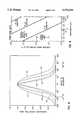
- FIG. 7is a graph showing the magnitude of the return signal from a rolling projectile versus time for the retroreflectors of FIGS. 3, 4, and 6;
- FIG. 8is a graph showing the relationship between the normalized reflecting area and the angle of incidence for the retroreflector structures shown in FIGS. 3, 4, and 6;
- FIG. 9is a graph showing effective cross sectional area versus wavelength for various corner reflector sizes.
- Projectile guidance system 100includes one or more projectiles 102 and one or more launching devices 104.
- Launching device 104contains electromagnetic transceiver 106 having transmitter 108 for the transmission of electromagnetic radiation of a predetermined wavelength, and receiver 110 for the reception of reflected electromagnetic radiation transmitted by transmitter 108.
- the transceiveris illustrated as operating in conjunction with antenna system 105, but preferably operates at optical frequencies.
- the launching devicealso includes command console 112 for issuing projectile control signals.
- the command consolemay consist, for example, of computer 114 and keyboard or keypad 116.
- the keypadis used to enter data specifying a desired projectile trajectory.
- the computerprocesses the entered data to produce control signals operative on the projectile to control its trajectory.
- the projectilecontains steering control hardware 118, which is responsive to the control signals issued by computer 114 by way of the electromagnetic link. These control signals include steering commands that are used to steer the projectile on a line-of-sight trajectory 120 toward a desired target 122.
- the projectilehas a central roll axis a-a' running approximately in the direction of projectile translational motion. The projectile may be engaged in a rolling or spinning motion about this central axis.
- Guidance system 100includes a vertical reference determination mechanism for ascertaining the local vertical reference of the projectile.
- the vertical reference informationis processed in command console 112 to derive steering commands for the projectile.
- the vertical reference determination mechanismincludes retroreflector 128 mounted on the projectile. Retroreflector 128 reflects a portion of the electromagnetic radiation transmitted by transmitter 108 back to receiver 110. Retroreflector 128 operates as a projectile roll detector for detecting missile roll or spin.
- the inventionis employed in the context of a combination of launching device 104 and projectile 102.
- projectile 102leaves launching device 104, the back end 139 of the projectile is facing the launching device.
- the projectileis normally provided with a slow spin about its central axis a-a'. This spin is on the order of 10 to 100 Hz and serves the primary purpose of averaging high speed erosion. Introduction of this spin is neither necessary nor particularly useful for projectile stabilization.
- a conventional prior art reflectorfor example, the reflector of FIG. 2
- a retroreflectorthat provides a return signal strongly dependent upon the spin of the projectile.
- the structure of projectile 102/retroreflector 128 assemblymay then be designed such that a minimum (or maximum) amount of energy is reflected back to transceiver 106 at the point in the spin rotation where the local vertical reference of the projectile coincides with the arbitrarily defined vertical axis of the guidance system.
- Retroreflector 129constructed in accordance with a preferred embodiment of the invention is shown in FIG. 3.
- Axis b-b' of the retroreflectoris situated at an angle theta ( ⁇ ) with respect to central axis a-a' of projectile 102. Therefore, retroreflector 129 may be denominated a canted retroreflector. Canting the retroreflector axis b-b' with respect to the central axis a-a' of projectile 102 results in a retroreflector having an angle of incidence and thus a signal return strongly dependent upon the instantaneous angle of rotation of the projectile.
- Retroreflector 129is shown centered on axis a-a', which is preferred because it produces a single signal minimum over a single full rotation. Placing it off of axis a-a' produces two such minima, which unnecessarily increase the complexity of the decoding electronics in command console 112 (FIG. 1).
- the incidence angle theta ( ⁇ ) between axes a-a' and b-b'is at a maximum.
- the optical energy transmitted by optical source 208is substantially parallel to axis a-a'.
- the canted surface of retroreflector 129reflects much of the incident optical energy along axis c-c' at an angle beta ( ⁇ ) with respect to axis a-a'.
- Much of the signal returned by the retroreflectortraverses along axis c-c', never reaching polarized mirror 207 and optical detector 209.
- the optical energy detected by the optical detector 209is at a minimum because incidence angle theta ( ⁇ ) is maximum (see FIG. 8).
- retroreflector 129Because of the design of retroreflector 129, as projectile 102 rotates the angle beta changes. When beta reaches a minimum value, the optical energy returned by retroreflector 129 is maximum because incident angle theta ( ⁇ ) is minimum. Accordingly, ,most of the returned optical energy reaches polarized mirror 207 and optical detector 209. Under these conditions, the detected optical energy is at a maximum.
- the canted retroreflector design of FIG. 3shows a simple technique for providing a return signal strongly dependent upon the instantaneous angular position of projectile 102. This dependency is weakest when axis a-a' is aligned with optical source 208 and strengthens as projectile 102 tilts away from alignment.
- the canted surface of retroreflector 129provides projectile guidance system 100 with roll detection means.
- the roll variation effectmay be obtained in any useful manner for the purpose of providing a retroreflector surface capable of indicating the instantaneous angular position of the projectile.
- FIG. 4illustrates an alternate embodiment of the invention in which one facet of a coaxially-mounted retroreflector 130 has been modified to provide a spoiling effect.
- a conventional retroreflector designmay contain, for example, four surfaces 131, 132, 133, 135 having substantially identical dimensions and arranged in a hornlike configuration.
- Such a retroreflector 130would exhibit properties similar to those of the prior art retroreflector 138 illustrated in FIG. 2, in that the incident and reflected optical energy travel along substantially parallel trajectories. The return signal is therefore virtually independent of the instantaneous rotational position of the retroreflector at a fixed incidence angle theta ( ⁇ ).
- the standard retroreflector design having four surfaces (facets) 131, 132, 133, 135may be modified by changing the position of one of the surfaces, such as surface 135, with reference to the remaining surfaces.
- FIG. 5illustrates the case where surface 135 has been positioned closer to surface 131 by distance d to form surface 134.
- Surfaces 132 and 133are modified as required to accommodate the new position of surface 134.
- the modified retroreflector 130has the reflective properties specified for the design set forth in FIG. 3, in that the retroreflector return signal is strongly dependent upon the instantaneous angular position of projectile 102.
- FIGS. 4 and 5illustrate a modified retroreflector structure in which the position of one of the prismatic retroreflector surfaces 135 has been changed from the symmetrical
- the positions of a plurality of surfaces 131, 132, 133, 135could be changed to provide instantaneous angular position detection means.
- Reflectivitymay be degraded by eliminating the reflective coating on selected surfaces or portions thereof, by coating selected surfaces or portions thereof with relatively nonreflective substances, or by totally eliminating selected surfaces or portions thereof.
- the aforementioned techniquesmay be combined, if desired, to meet certain specific system application requirements.
- FIG. 6a further alternate embodiment of the invention is shown that uses single-faceted retroreflector 154 for the roll detector.
- This retroreflectorcontains single facet 153 mounted at an angle alpha ( ⁇ ) with respect to projectile axis a-a'.
- the angle alphais approximately 45 degrees, such that a relatively high percentage of the incident optical energy is returned to optical detector 209 during a first portion of one projectile revolution, and a relatively low percentage of incident optical energy is returned during a second portion of one projectile revolution.
- the intensity of this effectdepends on misalignment of axis a-a' with source 208, which can be generally assumed. Other values for angle alpha are also useful.
- FIGS. 3, 4, and 6produce a reflection of electromagnetic radiation having a magnitude strongly dependent upon the instantaneous rotation angle of the projectile. It is common practice to refer to the instantaneous angle of rotation as projectile "spin" or "roll".
- FIG. 7illustrates a typical return signal for the retroreflectors of FIGS. 3, 4, and 6.
- Curve 63illustrates a return signal for a continuous-wave source of electromagnetic energy. The return signal oscillates at the spin frequency of the projectile.
- a source of pulsed electromagnetic energyproduces a return signal composed of pulses 67. Note that the returned pulses 67 follow the sinusoidal envelope of the return signal for the continuous-wave source.
- the local vertical reference of the projectilemay be calculated from the projectile spin.
- One technique for determining local vertical reference from spininvolves mounting retroreflector 128 (FIG. 1) on the projectile 102 such that the retroreflector returns a maximum (or minimum) amount of optical energy when the projectile is at a point in the spin rotation where the local vertical reference coincides with the defined vertical reference of projectile guidance system 100.
- the retroreflector 128 projectile 102 combination of the present inventionincludes vertical reference determination means.
- the vertical reference determination means of the retroreflector 128 projectile 102 combinationoperate in conjunction with the system components shown in FIG. 1.
- An oscillating signalsuch as the signal illustrated in FIG. 7, is received by the transceiver antenna system 105, amplified, filtered, and demodulated by receiver 110, and then conveyed to computer 114.
- Computer 114interprets the demodulated signal as establishing synchronicity for issuing one or more steering command signals required to keep the projectile on desired trajectory 120.
- the steering commandsare fed to transmitter 108, where the commands modulate a carrier wave consisting of electromagnetic radiation.
- the modulated carriercomprising a control signal is transmitted toward the target zone by means of transceiver antenna system 105.
- Launching device transceiver 106provides a communications link between projectile 102 and launching device 104.
- a laser or an RF command linkis the preferred method of communication from the launching device to the projectile during flight.
- Up-link communicationsare employed, such that transmitter 108 transmits a stream of pulses or a continuous wave signal to the projectile.
- Projectile retroreflector 128is mounted in the base 140 of the projectile, such that the retroreflector is situated in the line of sight of the transceiver.
- the transmitted control signalis received by steering control hardware 118 mounted onboard projectile 102.
- the steering control hardwarecontains circuits for opening and/or closing steering valves at a specified time interval after the projectile achieves a top dead center (vertical) orientation.
- the time intervalis specified by the control signal transmission timing, which is determined with reference to the oscillating vertical reference signal such as shown in FIG. 7.
- Steering valvescontrol the release of gas and/or fluid from the projectile, moving the projectile along the desired trajectory 120 such that it will hit target 122.
- the steering of projectile 102will be illustrated by way of example.
- the projectileis equipped with a first steering valve 143 mounted on surface 141.
- computer 114sends a steering command to the missile specifying the opening of the first steering valve 143, releasing propellant.
- Computer 114then commands the valve to close after the projectile achieves a one-quarter rotation clockwise from top dead center.
- the steps of opening and closing the valvemay repeat as soon as the missile again rotates around to the top dead center orientation. These steps may be repeated until the computer determines that the new projectile trajectory intercepts the target.
- First steering valve 143uses gasses or fluids under pressure to effect the translation of the projectile with respect to the established trajectory. These pressurized fluids can be supplied by the same mechanisms that generate the gasses used to cool the projectile by transpiration.
- the transpiration cooling system for the hyper-velocity projectilerequires a pressurized gas to be transfused into the nose cone area of the projectile or injected into the stagnation point of the projectile, as is known in the art.
- these pressurized gassesWhen used for steering purposes, these pressurized gasses are injected into the air stream flowing past the projectile body. This injection can be accomplished by opening a valve under the control of the steering computer 114 and the steering control hardware 118 as discussed above. These fluids need not be cold and can be produced by a pyrotechnic gas generator and stored momentarily until released by the valves for cooling or steering. For steering, these gasses require only sufficient mass flow to interact with the air stream and induce a shock wave that attaches or presses on the body of the projectile to exert a steering action.
- an explosive impulse systemmay be more advantageously employed.
- the explosive impulse systemtriggers the substantially instantaneous release, ignition, and explosion of a charge to correct the trajectory of the projectile.
- the steering forcesare created by a very small explosive charge detonated under the control of the steering computer 114 and steering control hardware 118.
- the impulse from such detonationis transmitted to the projectile body through an attenuator.
- a number of these precision impulse generators(not shown) can be located in a ring on the periphery of the projectile, to be fired by the computer 114 at the proper time for steering in the correct direction.
- the duration of the explosive pulseis in the microsecond range. In practical missile guidance systems, perhaps two or three corrective explosive impulses are required to achieve target intercept.
- Computer 114is equipped with an algorithm to apply correction commands to the projectile over a number of revolutions. The computer then predicts the path of the projectile to the target, which is necessarily line-of-sight from launching device 104. If target intercept is expected, no further trajectory corrections are required.
- FIG. 8is a graph illustrating the effective area (cross-section) of the retroreflector as a function of the angle of incidence.
- the cross-sectionis the effective area that the retroreflector presents to the incoming wavefront in the direction of the incident radiation. Accordingly, the graph of FIG. 8 effectively illustrates the amount of energy returned by various retroreflectors as a function of angle of incidence.
- Curve 51represents a solid triangular retroreflector with silvered mirror facets and a normalized reflecting area (N) of 100%.
- Curve 53was prepared using a triangular retroreflector with an open design.
- the presented area of a retroreflector surfaceis generally proportional to the percentage of returned electromagnetic energy. Accordingly, the retroreflector of the present invention returns a high percentage of the incident electromagnetic radiation across a relatively wide range of incident angles. For example, a normalized reflective area of 50% can be achieved at ten degrees from center with a circular retroreflector (curve 55) and at thirty degrees from center with a triangular retroreflector (curve 51).
- the electromagnetic transceiver 106may be equipped to operate in virtually any area of the electromagnetic spectrum, from very low frequency (VLF) up through the ultraviolet region.
- VLFvery low frequency
- the frequency range including infrared, visible, and ultraviolet lightthat is, optical wavelengths
- the energy returned by the retroreflectoris a function of wavelength. Shorter wavelengths, toward the ultraviolet end of the optical spectrum, result in relatively high energy returns. Longer wavelengths, toward the infrared end of the spectrum, produce lower energy returns.
- FIG. 9is a graph illustrating the design limitations inherent in corner reflector configurations across various wavelengths. The required size for a retroreflector mounted on board a 60-millimeter diameter projectile is well within the design constraint limitations set forth in FIG. 9.
- FIG. 9shows that a practical local vertical sensing system can be fabricated within the limits imposed by available fabrication accuracy, available dimensional stability in the operating environment, physical size limitations, and atmospheric coherence limitations. The useful physical size and atmospheric coherence limitations are shown substantially in the mid-region of FIG. 9.
Landscapes
- Engineering & Computer Science (AREA)
- Chemical & Material Sciences (AREA)
- Combustion & Propulsion (AREA)
- General Engineering & Computer Science (AREA)
- Aiming, Guidance, Guns With A Light Source, Armor, Camouflage, And Targets (AREA)
Abstract
Description
Claims (7)
Priority Applications (1)
| Application Number | Priority Date | Filing Date | Title |
|---|---|---|---|
| US08/051,402US5372334A (en) | 1993-04-23 | 1993-04-23 | Local vertical sensor for externally-guided projectiles |
Applications Claiming Priority (1)
| Application Number | Priority Date | Filing Date | Title |
|---|---|---|---|
| US08/051,402US5372334A (en) | 1993-04-23 | 1993-04-23 | Local vertical sensor for externally-guided projectiles |
Publications (1)
| Publication Number | Publication Date |
|---|---|
| US5372334Atrue US5372334A (en) | 1994-12-13 |
Family
ID=21971084
Family Applications (1)
| Application Number | Title | Priority Date | Filing Date |
|---|---|---|---|
| US08/051,402Expired - LifetimeUS5372334A (en) | 1993-04-23 | 1993-04-23 | Local vertical sensor for externally-guided projectiles |
Country Status (1)
| Country | Link |
|---|---|
| US (1) | US5372334A (en) |
Cited By (42)
| Publication number | Priority date | Publication date | Assignee | Title |
|---|---|---|---|---|
| US5647559A (en)* | 1994-07-16 | 1997-07-15 | Rheinmetall Industrie Gmbh | Apparatus for flight path correction of flying bodies |
| US5685504A (en)* | 1995-06-07 | 1997-11-11 | Hughes Missile Systems Company | Guided projectile system |
| US5691531A (en)* | 1995-11-09 | 1997-11-25 | Leigh Aerosystems Corporation | Data insertion system for modulating the carrier of a radio voice transmitter with missile control signals |
| US5708583A (en)* | 1995-04-24 | 1998-01-13 | Aerospatiale Societe Nationale Industrielle | System for determining the position and roll angle of a moving body |
| US5896106A (en)* | 1995-01-14 | 1999-04-20 | Oerlikon Contraves Gmbh | Method for determining the roll attitude of a rolling flying object |
| US5988562A (en)* | 1997-11-05 | 1999-11-23 | Linick; James M. | System and method for determining the angular orientation of a body moving in object space |
| RU2169333C1 (en)* | 2000-08-30 | 2001-06-20 | Государственное предприятие Научно-исследовательский институт приборостроения им. В.В. Тихомирова | Mobile brightening and guidance radar of antiaircraft-missile medium-range system |
| US6483455B2 (en)* | 1999-12-15 | 2002-11-19 | Thomson-Csf | Device for the unambiguous measurement of the roll of a projectile and application to the correction of the path of a projectile |
| RU2208213C1 (en)* | 2002-03-13 | 2003-07-10 | Государственное предприятие Научно-исследовательский институт приборостроения им. В.В.Тихомирова | Self-propelled antiaircraft rocket mount for detection, tracking and lighting of targets, guidance and launching of rockets of medium-range rocket complex |
| RU2223514C2 (en)* | 2001-12-17 | 2004-02-10 | Государственное унитарное предприятие "Конструкторское бюро приборостроения" | Method and device for measurement of coordinates |
| RU2223459C1 (en)* | 2002-09-04 | 2004-02-10 | Открытое акционерное общество "Научно-исследовательский институт приборостроения им. В.В.Тихомирова" | Self-propelled firing station for detection tracking and lighting of targets, guidance and launching of missiles of medium-range anti-aircraft missile complex |
| US6702184B2 (en)* | 2002-07-12 | 2004-03-09 | Symbol Technologies, Inc. | Collection optics for low profile single line scanning assembly in compact bar code readers |
| US6961555B1 (en)* | 1998-09-11 | 2005-11-01 | L.V. Partners, L.P. | System and apparatus for connecting a wireless device to a remote location on a network |
| US20050253017A1 (en)* | 2001-04-16 | 2005-11-17 | Knut Kongelbeck | Radar-directed projectile |
| US20060034150A1 (en)* | 2004-05-27 | 2006-02-16 | Scott Gary L | Water bottom cable seismic survey cable and system |
| WO2007015996A3 (en)* | 2005-07-26 | 2007-05-31 | Honeywell Int Inc | Apparatus and appertaining method for upfinding in spinning projectiles using a phase-lock-loop or correlator mechanism |
| RU2300777C2 (en)* | 2005-06-27 | 2007-06-10 | Государственное унитарное предприятие "Конструкторское бюро приборостроения" | Mode of measuring of coordinates and an arrangement for its execution |
| US20070156918A1 (en)* | 1998-09-11 | 2007-07-05 | L.V. Partners, Lp | Method for connecting a wireless device to a remote location on a network |
| US7333044B1 (en)* | 2006-09-25 | 2008-02-19 | The United States Of America As Represented By The Secretary Of The Army | Rocket-powered sensor target assembly |
| US20080105113A1 (en)* | 2006-10-04 | 2008-05-08 | Arthur Schneider | Supercapacitor power supply |
| RU2330307C1 (en)* | 2007-03-09 | 2008-07-27 | Открытое акционерное общество "Научно-исследовательский институт приборостроения имени В.В. Тихомирова" | Mid-range antiaircraft missile guidance mobile radar complex |
| US20080244004A1 (en)* | 1998-09-11 | 2008-10-02 | Lv Partners, L.P. | Launching a web site using a personal device |
| US7536478B2 (en) | 1998-09-11 | 2009-05-19 | Rpx-Lv Acquisition Llc | Method and apparatus for opening and launching a web browser in response to an audible signal |
| US7548988B2 (en) | 1998-09-11 | 2009-06-16 | Rpx-Lv Acquisition Llc | Software downloading using a television broadcast channel |
| RU2363911C1 (en)* | 2008-05-22 | 2009-08-10 | Открытое акционерное общество "Научно-исследовательский институт приборостроения имени В.В. Тихомирова" | Self-propelled complex with surface-to-air mean-range semiactive-homing rf-control misiles |
| US7636788B2 (en) | 1998-09-11 | 2009-12-22 | Rpx-Lv Acquisition Llc | Method and apparatus for matching a user's use profile in commerce with a broadcast |
| US7735423B1 (en)* | 2006-03-10 | 2010-06-15 | The United States Of America As Represented By The Secretary Of The Army | High visibility ordnance |
| US7819316B2 (en) | 1998-09-11 | 2010-10-26 | Lv Partners, L.P. | Portable scanner for enabling automatic commerce transactions |
| US7822829B2 (en) | 1998-09-11 | 2010-10-26 | Rpx-Lv Acquisition Llc | Method for interfacing scanned product information with a source for the product over a global network |
| US7823510B1 (en) | 2008-05-14 | 2010-11-02 | Pratt & Whitney Rocketdyne, Inc. | Extended range projectile |
| US20100307367A1 (en)* | 2008-05-14 | 2010-12-09 | Minick Alan B | Guided projectile |
| US7870189B2 (en) | 1998-09-11 | 2011-01-11 | Rpx-Lv Acquisition Llc | Input device having positional and scanning capabilities |
| US7904344B2 (en) | 1998-09-11 | 2011-03-08 | Rpx-Lv Acquisition Llc | Accessing a vendor web site using personal account information retrieved from a credit card company web site |
| US7908467B2 (en) | 1998-09-11 | 2011-03-15 | RPX-LV Acquistion LLC | Automatic configuration of equipment software |
| US7979576B2 (en) | 1998-09-11 | 2011-07-12 | Rpx-Lv Acquisition Llc | Method and apparatus for connecting a user location to one of a plurality of destination locations on a network |
| US8005985B2 (en) | 1998-09-11 | 2011-08-23 | RPX—LV Acquisition LLC | Method and apparatus for utilizing an audibly coded signal to conduct commerce over the internet |
| EP2511781A1 (en)* | 2011-04-14 | 2012-10-17 | Hexagon Technology Center GmbH | Method and system for controlling an unmanned aircraft |
| US8296440B2 (en) | 1998-09-11 | 2012-10-23 | Rpx Corporation | Method and apparatus for accessing a remote location with an optical reader having a programmable memory system |
| US20130206896A1 (en)* | 2010-01-29 | 2013-08-15 | Saab Ab | System and method for tracking and guiding at least one object |
| US20140028486A1 (en)* | 2011-09-09 | 2014-01-30 | Thales | Location system for a flying craft |
| US20160349746A1 (en)* | 2015-05-29 | 2016-12-01 | Faro Technologies, Inc. | Unmanned aerial vehicle having a projector and being tracked by a laser tracker |
| US9758239B2 (en) | 2011-04-14 | 2017-09-12 | Hexagon Technology Center Gmbh | System and method for controlling an unmanned air vehicle |
Citations (11)
| Publication number | Priority date | Publication date | Assignee | Title |
|---|---|---|---|---|
| US3995792A (en)* | 1974-10-15 | 1976-12-07 | The United States Of America As Represented By The Secretary Of The Army | Laser missile guidance system |
| US4003659A (en)* | 1974-11-15 | 1977-01-18 | The United States Of America As Represented By The Secretary Of The Army | Single plane corner reflector guidance system |
| US4047816A (en)* | 1976-06-18 | 1977-09-13 | The United States Of America As Represented By The Secretary Of The Army | Attitude determination using two transmitter/receiver stations and skewed reflectors |
| US4072281A (en)* | 1976-12-27 | 1978-02-07 | The United States Of America As Represented By The Secretary Of The Army | Optical attitude reference |
| US4096380A (en)* | 1975-07-28 | 1978-06-20 | Kurt Eichweber | System for transmitting light signals between a missile and a missile control station |
| US4123165A (en)* | 1977-05-31 | 1978-10-31 | The United States Of America As Represented By The Secretary Of The Army | Attitude determination using two color, dual-sweeping laser system |
| US4157544A (en)* | 1977-10-21 | 1979-06-05 | The United States Of America As Represented By The Secretary Of The Navy | Hybrid terminal assist landing |
| GB2041685A (en)* | 1978-12-13 | 1980-09-10 | Diehl Gmbh & Co | Means for automatically controlling a beam of electromagnetic radiation |
| JPS56125677A (en)* | 1980-03-07 | 1981-10-02 | Mitsubishi Electric Corp | Tracking device for infrared ray |
| US4709580A (en)* | 1986-02-26 | 1987-12-01 | Bd Systems, Inc. | Retroflective attitude determining system |
| US4990918A (en)* | 1989-12-21 | 1991-02-05 | University Of British Columbia | Radar reflector to enhance radar detection |
- 1993
- 1993-04-23USUS08/051,402patent/US5372334A/ennot_activeExpired - Lifetime
Patent Citations (11)
| Publication number | Priority date | Publication date | Assignee | Title |
|---|---|---|---|---|
| US3995792A (en)* | 1974-10-15 | 1976-12-07 | The United States Of America As Represented By The Secretary Of The Army | Laser missile guidance system |
| US4003659A (en)* | 1974-11-15 | 1977-01-18 | The United States Of America As Represented By The Secretary Of The Army | Single plane corner reflector guidance system |
| US4096380A (en)* | 1975-07-28 | 1978-06-20 | Kurt Eichweber | System for transmitting light signals between a missile and a missile control station |
| US4047816A (en)* | 1976-06-18 | 1977-09-13 | The United States Of America As Represented By The Secretary Of The Army | Attitude determination using two transmitter/receiver stations and skewed reflectors |
| US4072281A (en)* | 1976-12-27 | 1978-02-07 | The United States Of America As Represented By The Secretary Of The Army | Optical attitude reference |
| US4123165A (en)* | 1977-05-31 | 1978-10-31 | The United States Of America As Represented By The Secretary Of The Army | Attitude determination using two color, dual-sweeping laser system |
| US4157544A (en)* | 1977-10-21 | 1979-06-05 | The United States Of America As Represented By The Secretary Of The Navy | Hybrid terminal assist landing |
| GB2041685A (en)* | 1978-12-13 | 1980-09-10 | Diehl Gmbh & Co | Means for automatically controlling a beam of electromagnetic radiation |
| JPS56125677A (en)* | 1980-03-07 | 1981-10-02 | Mitsubishi Electric Corp | Tracking device for infrared ray |
| US4709580A (en)* | 1986-02-26 | 1987-12-01 | Bd Systems, Inc. | Retroflective attitude determining system |
| US4990918A (en)* | 1989-12-21 | 1991-02-05 | University Of British Columbia | Radar reflector to enhance radar detection |
Cited By (56)
| Publication number | Priority date | Publication date | Assignee | Title |
|---|---|---|---|---|
| US5647559A (en)* | 1994-07-16 | 1997-07-15 | Rheinmetall Industrie Gmbh | Apparatus for flight path correction of flying bodies |
| US5896106A (en)* | 1995-01-14 | 1999-04-20 | Oerlikon Contraves Gmbh | Method for determining the roll attitude of a rolling flying object |
| US5708583A (en)* | 1995-04-24 | 1998-01-13 | Aerospatiale Societe Nationale Industrielle | System for determining the position and roll angle of a moving body |
| US5685504A (en)* | 1995-06-07 | 1997-11-11 | Hughes Missile Systems Company | Guided projectile system |
| US5691531A (en)* | 1995-11-09 | 1997-11-25 | Leigh Aerosystems Corporation | Data insertion system for modulating the carrier of a radio voice transmitter with missile control signals |
| US5988562A (en)* | 1997-11-05 | 1999-11-23 | Linick; James M. | System and method for determining the angular orientation of a body moving in object space |
| US8005985B2 (en) | 1998-09-11 | 2011-08-23 | RPX—LV Acquisition LLC | Method and apparatus for utilizing an audibly coded signal to conduct commerce over the internet |
| US7548988B2 (en) | 1998-09-11 | 2009-06-16 | Rpx-Lv Acquisition Llc | Software downloading using a television broadcast channel |
| US7979576B2 (en) | 1998-09-11 | 2011-07-12 | Rpx-Lv Acquisition Llc | Method and apparatus for connecting a user location to one of a plurality of destination locations on a network |
| US7870189B2 (en) | 1998-09-11 | 2011-01-11 | Rpx-Lv Acquisition Llc | Input device having positional and scanning capabilities |
| US7739353B2 (en) | 1998-09-11 | 2010-06-15 | Rpx-Lv Acquisition Llc | Launching a web site using a personal device |
| US7636788B2 (en) | 1998-09-11 | 2009-12-22 | Rpx-Lv Acquisition Llc | Method and apparatus for matching a user's use profile in commerce with a broadcast |
| US6961555B1 (en)* | 1998-09-11 | 2005-11-01 | L.V. Partners, L.P. | System and apparatus for connecting a wireless device to a remote location on a network |
| US8069098B2 (en) | 1998-09-11 | 2011-11-29 | Rpx-Lv Acquisition Llc | Input device for allowing interface to a web site in association with a unique input code |
| US7912760B2 (en) | 1998-09-11 | 2011-03-22 | Rpx-Lv Acquisition Llc | Method and apparatus for utilizing a unique transaction code to update a magazine subscription over the internet |
| US7925780B2 (en) | 1998-09-11 | 2011-04-12 | Rpx-Lv Acquisition Llc | Method for connecting a wireless device to a remote location on a network |
| US7908467B2 (en) | 1998-09-11 | 2011-03-15 | RPX-LV Acquistion LLC | Automatic configuration of equipment software |
| US7904344B2 (en) | 1998-09-11 | 2011-03-08 | Rpx-Lv Acquisition Llc | Accessing a vendor web site using personal account information retrieved from a credit card company web site |
| US20070156918A1 (en)* | 1998-09-11 | 2007-07-05 | L.V. Partners, Lp | Method for connecting a wireless device to a remote location on a network |
| US7819316B2 (en) | 1998-09-11 | 2010-10-26 | Lv Partners, L.P. | Portable scanner for enabling automatic commerce transactions |
| US7822829B2 (en) | 1998-09-11 | 2010-10-26 | Rpx-Lv Acquisition Llc | Method for interfacing scanned product information with a source for the product over a global network |
| US7912961B2 (en) | 1998-09-11 | 2011-03-22 | Rpx-Lv Acquisition Llc | Input device for allowing input of unique digital code to a user's computer to control access thereof to a web site |
| US8296440B2 (en) | 1998-09-11 | 2012-10-23 | Rpx Corporation | Method and apparatus for accessing a remote location with an optical reader having a programmable memory system |
| US20080244004A1 (en)* | 1998-09-11 | 2008-10-02 | Lv Partners, L.P. | Launching a web site using a personal device |
| US7536478B2 (en) | 1998-09-11 | 2009-05-19 | Rpx-Lv Acquisition Llc | Method and apparatus for opening and launching a web browser in response to an audible signal |
| US6483455B2 (en)* | 1999-12-15 | 2002-11-19 | Thomson-Csf | Device for the unambiguous measurement of the roll of a projectile and application to the correction of the path of a projectile |
| RU2169333C1 (en)* | 2000-08-30 | 2001-06-20 | Государственное предприятие Научно-исследовательский институт приборостроения им. В.В. Тихомирова | Mobile brightening and guidance radar of antiaircraft-missile medium-range system |
| US7079070B2 (en)* | 2001-04-16 | 2006-07-18 | Alliant Techsystems Inc. | Radar-filtered projectile |
| US20050253017A1 (en)* | 2001-04-16 | 2005-11-17 | Knut Kongelbeck | Radar-directed projectile |
| RU2223514C2 (en)* | 2001-12-17 | 2004-02-10 | Государственное унитарное предприятие "Конструкторское бюро приборостроения" | Method and device for measurement of coordinates |
| RU2208213C1 (en)* | 2002-03-13 | 2003-07-10 | Государственное предприятие Научно-исследовательский институт приборостроения им. В.В.Тихомирова | Self-propelled antiaircraft rocket mount for detection, tracking and lighting of targets, guidance and launching of rockets of medium-range rocket complex |
| US6702184B2 (en)* | 2002-07-12 | 2004-03-09 | Symbol Technologies, Inc. | Collection optics for low profile single line scanning assembly in compact bar code readers |
| RU2223459C1 (en)* | 2002-09-04 | 2004-02-10 | Открытое акционерное общество "Научно-исследовательский институт приборостроения им. В.В.Тихомирова" | Self-propelled firing station for detection tracking and lighting of targets, guidance and launching of missiles of medium-range anti-aircraft missile complex |
| US20060034150A1 (en)* | 2004-05-27 | 2006-02-16 | Scott Gary L | Water bottom cable seismic survey cable and system |
| RU2300777C2 (en)* | 2005-06-27 | 2007-06-10 | Государственное унитарное предприятие "Конструкторское бюро приборостроения" | Mode of measuring of coordinates and an arrangement for its execution |
| US7395987B2 (en) | 2005-07-26 | 2008-07-08 | Honeywell International Inc. | Apparatus and appertaining method for upfinding in spinning projectiles using a phase-lock-loop or correlator mechanism |
| WO2007015996A3 (en)* | 2005-07-26 | 2007-05-31 | Honeywell Int Inc | Apparatus and appertaining method for upfinding in spinning projectiles using a phase-lock-loop or correlator mechanism |
| US7735423B1 (en)* | 2006-03-10 | 2010-06-15 | The United States Of America As Represented By The Secretary Of The Army | High visibility ordnance |
| US7333044B1 (en)* | 2006-09-25 | 2008-02-19 | The United States Of America As Represented By The Secretary Of The Army | Rocket-powered sensor target assembly |
| US7946209B2 (en)* | 2006-10-04 | 2011-05-24 | Raytheon Company | Launcher for a projectile having a supercapacitor power supply |
| US20080105113A1 (en)* | 2006-10-04 | 2008-05-08 | Arthur Schneider | Supercapacitor power supply |
| RU2330307C1 (en)* | 2007-03-09 | 2008-07-27 | Открытое акционерное общество "Научно-исследовательский институт приборостроения имени В.В. Тихомирова" | Mid-range antiaircraft missile guidance mobile radar complex |
| US20100307367A1 (en)* | 2008-05-14 | 2010-12-09 | Minick Alan B | Guided projectile |
| US7823510B1 (en) | 2008-05-14 | 2010-11-02 | Pratt & Whitney Rocketdyne, Inc. | Extended range projectile |
| US7891298B2 (en) | 2008-05-14 | 2011-02-22 | Pratt & Whitney Rocketdyne, Inc. | Guided projectile |
| RU2363911C1 (en)* | 2008-05-22 | 2009-08-10 | Открытое акционерное общество "Научно-исследовательский институт приборостроения имени В.В. Тихомирова" | Self-propelled complex with surface-to-air mean-range semiactive-homing rf-control misiles |
| US20130206896A1 (en)* | 2010-01-29 | 2013-08-15 | Saab Ab | System and method for tracking and guiding at least one object |
| US9000340B2 (en)* | 2010-01-29 | 2015-04-07 | Saab Ab | System and method for tracking and guiding at least one object |
| WO2012140191A1 (en)* | 2011-04-14 | 2012-10-18 | Hexagon Technology Center Gmbh | System and method for controlling an unmanned air vehicle |
| EP2511781A1 (en)* | 2011-04-14 | 2012-10-17 | Hexagon Technology Center GmbH | Method and system for controlling an unmanned aircraft |
| CN103492967A (en)* | 2011-04-14 | 2014-01-01 | 赫克斯冈技术中心 | System and method for controlling an unmanned air vehicle |
| AU2012241780B2 (en)* | 2011-04-14 | 2015-04-23 | Hexagon Technology Center Gmbh | System and method for controlling an unmanned air vehicle |
| US9758239B2 (en) | 2011-04-14 | 2017-09-12 | Hexagon Technology Center Gmbh | System and method for controlling an unmanned air vehicle |
| US20140028486A1 (en)* | 2011-09-09 | 2014-01-30 | Thales | Location system for a flying craft |
| US9348011B2 (en)* | 2011-09-09 | 2016-05-24 | Thales | Location system for a flying craft |
| US20160349746A1 (en)* | 2015-05-29 | 2016-12-01 | Faro Technologies, Inc. | Unmanned aerial vehicle having a projector and being tracked by a laser tracker |
Similar Documents
| Publication | Publication Date | Title |
|---|---|---|
| US5372334A (en) | Local vertical sensor for externally-guided projectiles | |
| US4097007A (en) | Missile guidance system utilizing polarization | |
| US5685504A (en) | Guided projectile system | |
| US4641801A (en) | Terminally guided weapon delivery system | |
| US5102065A (en) | System to correct the trajectory of a projectile | |
| US4123165A (en) | Attitude determination using two color, dual-sweeping laser system | |
| US5131602A (en) | Apparatus and method for remote guidance of cannon-launched projectiles | |
| US4047816A (en) | Attitude determination using two transmitter/receiver stations and skewed reflectors | |
| US5973309A (en) | Target-tracking laser designation | |
| US6653972B1 (en) | All weather precision guidance of distributed projectiles | |
| US5478028A (en) | Tracking and guidance techniques for semi-ballistic rounds | |
| EP1366334B1 (en) | Precision-guided hypersonic projectile weapon system | |
| US4576346A (en) | Seeker head for a target seeking missile | |
| WO1996025641A2 (en) | Method and apparatus for radial thrust trajectory correction of a ballistic projectile | |
| US6568627B1 (en) | Side-scatter beamrider missile guidance system | |
| KR20160114582A (en) | Interception missile and warhead therefor | |
| US6738012B1 (en) | Protecting commercial airliners from man portable missiles | |
| GB2212252A (en) | Missile defence system. | |
| US5664741A (en) | Nutated beamrider guidance using laser designators | |
| US4728057A (en) | Spin-stabilized projectile with pulse receiver and method of use | |
| US4951901A (en) | Spin-stabilized projectile with pulse receiver and method of use | |
| US4625647A (en) | Weapon system and missile for the structural destruction of an aerial target by means of a focussed charge | |
| US6138944A (en) | Scatterider guidance system for a flying object based on maintenance of minimum distance between the designating laser beam and the longitudinal axis of the flying object | |
| CA1242516A (en) | Terminally guided weapon delivery system | |
| US4696441A (en) | Missile referenced beamrider |
Legal Events
| Date | Code | Title | Description |
|---|---|---|---|
| AS | Assignment | Owner name:HUGHES AIRCRAFT MISSILE SYSTEMS COMPANY, CALIFORNI Free format text:ASSIGNMENT OF ASSIGNORS INTEREST;ASSIGNOR:CUADROS, JAIME H.;REEL/FRAME:006538/0189 Effective date:19930414 Owner name:HUGHES MISSILE SYSTEMS COMPANY, CALIFORNIA Free format text:ASSIGNMENT OF ASSIGNORS INTEREST;ASSIGNOR:CUADROS, JAIME H.;REEL/FRAME:006538/0189 Effective date:19930414 | |
| STPP | Information on status: patent application and granting procedure in general | Free format text:APPLICATION UNDERGOING PREEXAM PROCESSING | |
| FPAY | Fee payment | Year of fee payment:4 | |
| FPAY | Fee payment | Year of fee payment:8 | |
| AS | Assignment | Owner name:RAYTHEON MISSILE SYSTEMS COMPANY, MASSACHUSETTS Free format text:CHANGE OF NAME;ASSIGNOR:HUGHES MISSILE SYSTEMS COMPANY;REEL/FRAME:015596/0693 Effective date:19971217 Owner name:RAYTHEON COMPANY, MASSACHUSETTS Free format text:MERGER;ASSIGNOR:RAYTHEON MISSILE SYSTEMS COMPANY;REEL/FRAME:015612/0545 Effective date:19981229 | |
| FPAY | Fee payment | Year of fee payment:12 | |
| AS | Assignment | Owner name:OL SECURITY LIMITED LIABILITY COMPANY, DELAWARE Free format text:ASSIGNMENT OF ASSIGNORS INTEREST;ASSIGNOR:RAYTHEON COMPANY;REEL/FRAME:029117/0335 Effective date:20120730 |