US5371734A - Medium access control protocol for wireless network - Google Patents
Medium access control protocol for wireless networkDownload PDFInfo
- Publication number
- US5371734A US5371734AUS08/011,415US1141593AUS5371734AUS 5371734 AUS5371734 AUS 5371734AUS 1141593 AUS1141593 AUS 1141593AUS 5371734 AUS5371734 AUS 5371734A
- Authority
- US
- United States
- Prior art keywords
- hub
- frames
- remotes
- remote
- communicator
- Prior art date
- Legal status (The legal status is an assumption and is not a legal conclusion. Google has not performed a legal analysis and makes no representation as to the accuracy of the status listed.)
- Expired - Lifetime
Links
- 230000006854communicationEffects0.000claimsabstractdescription385
- 238000004891communicationMethods0.000claimsabstractdescription384
- 230000005540biological transmissionEffects0.000claimsabstractdescription201
- 230000006870functionEffects0.000claimsabstractdescription75
- 238000012546transferMethods0.000claimsdescription77
- 230000000694effectsEffects0.000claimsdescription36
- 230000007480spreadingEffects0.000claimsdescription26
- 238000001228spectrumMethods0.000claimsdescription24
- 230000004044responseEffects0.000claimsdescription17
- 230000003466anti-cipated effectEffects0.000claimsdescription5
- 238000012544monitoring processMethods0.000claimsdescription4
- 238000000034methodMethods0.000abstractdescription31
- 108700026140MAC combinationProteins0.000abstractdescription28
- 230000009286beneficial effectEffects0.000abstractdescription4
- 230000000593degrading effectEffects0.000abstractdescription2
- 238000010586diagramMethods0.000description15
- 230000001427coherent effectEffects0.000description11
- 230000008569processEffects0.000description8
- 230000008901benefitEffects0.000description6
- 238000001514detection methodMethods0.000description6
- 230000006872improvementEffects0.000description6
- 230000006855networkingEffects0.000description6
- 230000001360synchronised effectEffects0.000description5
- 125000004122cyclic groupChemical group0.000description4
- 238000005516engineering processMethods0.000description4
- 229920006395saturated elastomerPolymers0.000description4
- 230000007704transitionEffects0.000description4
- 230000003213activating effectEffects0.000description3
- 230000003044adaptive effectEffects0.000description3
- 230000002146bilateral effectEffects0.000description3
- 239000000872bufferSubstances0.000description3
- 230000008859changeEffects0.000description3
- 230000001066destructive effectEffects0.000description3
- 238000007726management methodMethods0.000description3
- 238000000926separation methodMethods0.000description3
- 230000008054signal transmissionEffects0.000description3
- 230000001934delayEffects0.000description2
- 238000009432framingMethods0.000description2
- 238000005259measurementMethods0.000description2
- 230000000737periodic effectEffects0.000description2
- 230000010363phase shiftEffects0.000description2
- JBRZTFJDHDCESZ-UHFFFAOYSA-NAsGaChemical compound[As]#[Ga]JBRZTFJDHDCESZ-UHFFFAOYSA-N0.000description1
- 229910001218Gallium arsenideInorganic materials0.000description1
- 230000004913activationEffects0.000description1
- 230000002902bimodal effectEffects0.000description1
- 230000000739chaotic effectEffects0.000description1
- 238000012937correctionMethods0.000description1
- 239000013078crystalSubstances0.000description1
- 238000011161developmentMethods0.000description1
- 230000003292diminished effectEffects0.000description1
- 239000000284extractSubstances0.000description1
- 238000005562fadingMethods0.000description1
- 230000005669field effectEffects0.000description1
- 230000010365information processingEffects0.000description1
- 238000009434installationMethods0.000description1
- 230000003993interactionEffects0.000description1
- 230000002452interceptive effectEffects0.000description1
- 230000002045lasting effectEffects0.000description1
- 238000012423maintenanceMethods0.000description1
- 239000000203mixtureSubstances0.000description1
- 239000013307optical fiberSubstances0.000description1
- 238000012545processingMethods0.000description1
- 230000035755proliferationEffects0.000description1
- 239000010453quartzSubstances0.000description1
- 230000009467reductionEffects0.000description1
- 238000009877renderingMethods0.000description1
- 238000012163sequencing techniqueMethods0.000description1
- 230000011664signalingEffects0.000description1
- VYPSYNLAJGMNEJ-UHFFFAOYSA-Nsilicon dioxideInorganic materialsO=[Si]=OVYPSYNLAJGMNEJ-UHFFFAOYSA-N0.000description1
- 230000003068static effectEffects0.000description1
- 239000000126substanceSubstances0.000description1
Images


Classifications
- H—ELECTRICITY
- H04—ELECTRIC COMMUNICATION TECHNIQUE
- H04W—WIRELESS COMMUNICATION NETWORKS
- H04W52/00—Power management, e.g. Transmission Power Control [TPC] or power classes
- H04W52/02—Power saving arrangements
- H04W52/0209—Power saving arrangements in terminal devices
- H04W52/0261—Power saving arrangements in terminal devices managing power supply demand, e.g. depending on battery level
- H04W52/0274—Power saving arrangements in terminal devices managing power supply demand, e.g. depending on battery level by switching on or off the equipment or parts thereof
- H—ELECTRICITY
- H04—ELECTRIC COMMUNICATION TECHNIQUE
- H04W—WIRELESS COMMUNICATION NETWORKS
- H04W4/00—Services specially adapted for wireless communication networks; Facilities therefor
- H04W4/06—Selective distribution of broadcast services, e.g. multimedia broadcast multicast service [MBMS]; Services to user groups; One-way selective calling services
- H—ELECTRICITY
- H04—ELECTRIC COMMUNICATION TECHNIQUE
- H04W—WIRELESS COMMUNICATION NETWORKS
- H04W48/00—Access restriction; Network selection; Access point selection
- H04W48/08—Access restriction or access information delivery, e.g. discovery data delivery
- H—ELECTRICITY
- H04—ELECTRIC COMMUNICATION TECHNIQUE
- H04W—WIRELESS COMMUNICATION NETWORKS
- H04W72/00—Local resource management
- H04W72/12—Wireless traffic scheduling
- H—ELECTRICITY
- H04—ELECTRIC COMMUNICATION TECHNIQUE
- H04W—WIRELESS COMMUNICATION NETWORKS
- H04W76/00—Connection management
- H04W76/10—Connection setup
- H—ELECTRICITY
- H04—ELECTRIC COMMUNICATION TECHNIQUE
- H04W—WIRELESS COMMUNICATION NETWORKS
- H04W84/00—Network topologies
- H04W84/02—Hierarchically pre-organised networks, e.g. paging networks, cellular networks, WLAN [Wireless Local Area Network] or WLL [Wireless Local Loop]
- H04W84/10—Small scale networks; Flat hierarchical networks
- H04W84/12—WLAN [Wireless Local Area Networks]
- H—ELECTRICITY
- H04—ELECTRIC COMMUNICATION TECHNIQUE
- H04W—WIRELESS COMMUNICATION NETWORKS
- H04W88/00—Devices specially adapted for wireless communication networks, e.g. terminals, base stations or access point devices
- H04W88/02—Terminal devices
- H04W88/04—Terminal devices adapted for relaying to or from another terminal or user
- Y—GENERAL TAGGING OF NEW TECHNOLOGICAL DEVELOPMENTS; GENERAL TAGGING OF CROSS-SECTIONAL TECHNOLOGIES SPANNING OVER SEVERAL SECTIONS OF THE IPC; TECHNICAL SUBJECTS COVERED BY FORMER USPC CROSS-REFERENCE ART COLLECTIONS [XRACs] AND DIGESTS
- Y02—TECHNOLOGIES OR APPLICATIONS FOR MITIGATION OR ADAPTATION AGAINST CLIMATE CHANGE
- Y02D—CLIMATE CHANGE MITIGATION TECHNOLOGIES IN INFORMATION AND COMMUNICATION TECHNOLOGIES [ICT], I.E. INFORMATION AND COMMUNICATION TECHNOLOGIES AIMING AT THE REDUCTION OF THEIR OWN ENERGY USE
- Y02D30/00—Reducing energy consumption in communication networks
- Y02D30/70—Reducing energy consumption in communication networks in wireless communication networks
Definitions
- This inventionrelates to an invention for a Technique for Bridging Local Area Networks Having Non-Unique Node Addresses, Ser. No. 08/011,361, filed concurrently herewith, by the inventor hereof, and assigned to the assignee of this Application.
- the disclosure of this related inventionis incorporated herein by this reference.
- This inventionrelates to a technique and protocol for connecting multiple distinct computer resources by radio frequency (RF) or other wireless communications to establish a single logical network of the resources to permit communication between the distinct resources similar to that of a local area network (LAN). Even more specifically, the present invention relates to a medium access control (MAC) technique or protocol for selectively activating and deactivating the transmitters and receivers of the means for communicating between the resources to save electrical power consumed while still permitting LAN-like functionality, thereby extending considerably the ability of the resources to remain operable when battery powered.
- RFradio frequency
- MACmedium access control
- a LANis a well-known means of achieving communication between different resources, typically computer resources such as computers, work stations, printers and the like.
- the LANitself includes a network interface connected to each resource and a physical communication medium connecting all of the interfaces.
- the interface and connected resourceconstitute a node.
- Each nodehas an unambiguous address or identification (ID).
- Communication between nodesis typically accomplished by sending and receiving an ordered Group of bits known as a frame or packet. Each frame is sent from a source node, and is received by a destination node.
- the ID of the source node (SID) and the ID of the destination node (DID)are frequently included within the frame in Groups of sequential bits known as fields.
- the technique of communicating between the nodes, and of controlling the composition of framesis defined by a network protocol.
- the network protocolincludes a MAC aspect which establishes an orderly and predictable ability of each node to access the medium, for the purposes of communicating with another node by transmitting and receiving frames, of requesting access to the medium and acknowledging previous frame communication.
- a MAC aspectwhich establishes an orderly and predictable ability of each node to access the medium, for the purposes of communicating with another node by transmitting and receiving frames, of requesting access to the medium and acknowledging previous frame communication.
- chaotic and inefficient communicationif any, would prevail, because it is highly unlikely that the frames sent from the source node would reach the destination node without interference and disruption caused by conflicting frames sent by another node at the same or overlapping time periods or at a time that the destination node was not ready to receive a frame. Therefore, the MAC facilities are one of the very important aspects of any LAN-like communication protocol among a plurality of equal peer-type transmitting and receiving stations such as nodes.
- a LANcan present a significant impediment when it is recognized that all of the resources must me wired together, particularly if the resources are physically separated and numerous. It is not unusual that many thousands or tens of thousands of feet or meters of cable may be required to connect a few tens or hundreds of resources, even when none of the resources is separated by more than a few hundreds of feet or meters. In existing facilities, sufficient physical access may not be available to route the necessary cabling. Installation, even if possible, may be very expensive. Even in designing and constructing new facilities, the cable expense itself for networking among a large number of personal computers or work stations may be cost-prohibitive.
- Networks of LAN-like functionalityhave been established in the past by implementing the communication medium with wireless RF links between the resources.
- One difficulty presented by such systemsis that MAC becomes considerably more difficult, because the RF links do not permit the transmitting and receiving stations (akin to nodes on a LAN) to sense the use of the medium (the RF signals) as reliably as in a wired network.
- Timing and synchronization requirements for the transmission of messages, static and interference from sources of RF noise, transmission and reception range limitations, multipath interference and fading and other known difficultiesall become significant concerns and limitations in implementing MAC protocols for wireless networks. These same concerns are generally not regarded as highly significant in wired or optical fiber networks because the integrity of the cabled medium usually avoids most if not all of these concerns.
- the integrity of the wired communication mediumusually eliminates or significantly reduces the concerns about interference because the cabling offers inherent shielding from interference. Because the integrity of the communication is essentially assured in transmissions over the wires, range and signalling issues generally do not become significant. Light links have also been employed in networks, but the difficulties with light linked networks are usually even more exaggerated because of the directionality required for directing light beams in unobstructed, line-of-sight, signal paths.
- carrier-sense multiple accesseach station uses its receiver to monitor the network medium for other transmission activity prior to activating its transmitter. If any such activity is detected, the station waits until a predetermined time after the end of the detected network activity. If two or more stations begin transmitting at close enough to the same point in time so that none of these stations detect each other's transmission, the resulting transmissions are said to collide, with the result that none of the frames being transmitted by these stations are able to be successfully received at their intended destinations.
- CSMA protocolsoffer very low latency to begin communication during periods when little or no other network message traffic is active, they perform poorly when many stations are contending for access to the medium to send frames or when the aggregate amount to be transmitted exceeds about half of the data bandwidth of the network medium.
- wireless CSMA networkshave increased chances for collisions when compared with wired CSMA networks, because obstructions to RF signal propagation could permit a station to erroneously detect an available network medium, allowing that station to activate its transmitter while another station was in the process of sending a frame.
- TDMAtime division multiple access
- the available time for the multiplicity of the stations to access and use the radio linksis divided among each of the stations.
- Each stationhas its own predesignated and assigned time Txop for communicating RF messages with other stations.
- Each stationrecognizes and operates under recognition of the order and sequence of the time Txops assigned to the other stations, to avoid overlap and conflict in the communications.
- TDMA protocolsWhile TDMA protocols are generally very effective in providing reliably recognized opportunities for communicating messages, they can result in a reduced capacity or data bandwidth for transmitting information between stations when the communications are intermittent quantities of variable length messages ("bursts"). In burst message situations, which are highly typical of LAN-type communications, TDMA results in reduced useable data bandwidth because a large portion of the available time is unused for data communications because that time is assigned to stations that have nothing to send when their time slots occur. In situations where one station may have a considerable amount to send, the information must be broken up into parts and sent in sequence, one part each time the station's time occurs. Thus, TDMA, while providing reliable medium access in the difficult medium access environment of wireless networks, does not provide the higher message throughput or bandwidth as do some of the more traditional LANs.
- PRMApacket reservation multiple access
- each of the multiplicity of the stationsmust request and reserve a time to access and use the radio link to send its packets or frames.
- the requestsare made on the basis of the amount of time that each station expects to use in communicating the amount of information it has queued for delivery to another station.
- the available time for all the stations to communicateis divided among each of the stations according to the requests of the stations.
- the time allocation reserved for each stationis communicated to all of the stations, so all of the stations recognize which stations have a time allocation, how long the time allocation is and in what order the stations will receive and use their allocations. After this information is conveyed, each station requesting time uses its reserved time in its assigned order to communicate packets or frames with other stations.
- PRMA techniquesare more effective than TDMA techniques in utilizing the available time, because only those stations with messages to send need to be provided with an opportunity to send messages.
- fast response to requestsis impossible because of the delays inherent in obtaining a reservation.
- a considerable amount of the available timeis consumed in the rather complex communication of control information, referred to as "overhead.”
- the overheadis used for requesting time, allocating a reservation of time, communicating the amount of time reserved, communicating the order in which the stations receive the time reservations, and the like. As a consequence, the quantity of useful data bandwidth of PRMA networks is also limited.
- Portable computersallow computational tasks to be performed wherever the user happens to be located.
- Portable computersare usually used during travel, because portability is their primary advantage. Even during travel, however, there may be a need to access other computer resources through the portable computer, just as is more typically done with stationary resources. It may desirable to create temporary, ad hoc networks of portable computers so that, for example, users can network their portable computers to exchange data in meetings and classrooms. Of course in these situations, physically connecting the portable computers to a wired network medium may be inconvenient or impossible.
- the users and their locationsmay not be specifically predefined, and may change intermittently.
- the transmitters and receiversIn addition, to connect portable computers with RF or other wireless networking capability, it is necessary that the transmitters and receivers also operate from battery power, otherwise one of the primary benefits of wireless networking is negated by requiring the use of a power wire instead of a network medium wire. The additional power drain resulting from operating the transmitters and receivers diminishes the available power for the portable computer. If separate batteries are employed for the transmitter and receiver on one hand and for the portable computer on the other hand, the batteries for the transmitter and receiver should be able to provide as much longevity of use for the transmitter and receiver as the batteries for the portable computer provide, without being so large or heavy as to interfere with portability.
- a major obstacle to adequate battery life for battery-operated wireless network interfacesis that conventional MAC protocols, whether using CSMA techniques, TDMA techniques, PRMA techniques, or other techniques (such as token passing), all assume that the network receivers are capable of receiving frames at all times that they are not actively transmitting. Consequently these MAC prior techniques are concerned only with controlling access to the network medium by transmitters. Because low-power, short-distance radio transceivers consume about as much electrical power in their receiving function as in their transmitting function, a useful protocol for battery operated networking must avoid this assumption, and must concern itself with the access to the network medium by the receivers as well as the transmitters.
- the MAC protocol of the present inventionprovides the reliable, predictable aspects of medium access similar to those obtained in TDMA, and also provides the more effective allocation of available bandwidth among those resources which have messages to send, similar to those available from PRMA.
- the MAC protocol of the present inventionavoids many of the disadvantages associated with the inefficiencies of LAN-type burst communications in TDMA, the high overhead requirements for communications in PRMA, and the problems of avoiding collisions and saturation that affect CSMA.
- the present inventionprovides a MAC protocol which may be very effectively implemented with communicator stations used with portable computers, because it obtains significant reductions in battery power drain by permitting the receivers as well as the transmitters of the communicator stations to be powered off during a majority of the time, but selectively and predictably powered on to send or receive relevant communications.
- a communicator station or communicatorwirelessly transmits frames to and receives frames from a least one additional communicator in accordance with a predetermined MAC protocol.
- Each communicatorincludes a transmitter and a receiver. The communication occurs among members of a Group of communicators.
- the MAC protocolcontrols each communicator of the Group.
- One of the communicators of the Groupis designated as a "hub” and the remaining communicators are designated as "remotes".
- the hubestablishes repeating communication cycles, each of which has intervals during which the hub and the remotes transmit and receive frames.
- the hubtransmits control information to the remotes to establish the communication cycle and to establish a plurality of predeterminable intervals during each communication cycle.
- intervalsallow the hub to transmit frames to the remotes, allow the remotes to transmit frames to the hub, and allow each remote to anticipate receiving frames from the hub. Due to the defined intervals of the communication cycle and the information conveyed by the hub, the remotes are able to power off their transmitters during times other than those intervals when the remote is allowed to transmit frames to the hub. In addition, and very significantly, the remotes are able to power off their receivers during times other than those intervals when the remote is expected to receive frames from the hub. Thus, the control information and the communication cycle conserve considerable power because the receivers and transmitters of the remotes may remain powered off for a considerable portion of time without degrading communications.
- Txopstransmission opportunities
- the huballocates transmission opportunities (Txops) to the remotes, preferably based on bandwidth requests from the hubs.
- Txop allocation informationis communicated to the remotes.
- Previous Txop allocationsmay be revoked or relinquished for non-use or very low use as determined by the hub monitoring the frames transmitted by each remote, for example.
- the Txop allocationsmay be varied or adjusted by the hub from one communication cycle to the next to account for changes in activity of the remotes. The adjustment occurs in relation to the number of frames or quantity of data transmitted by each remote during recent communication cycles.
- the desirable aspects of TDMAare achieved by providing specific predeterminable intervals for Txops, and the desirable aspects of PRMA are achieved by adjusting the durations of the Txops to accommodate the communication of the more active remotes.
- Battery power concernsare addressed by allowing the predeterminable intervals for receiving frames, thus allowing the receivers to be powered off until the frames are anticipated.
- Another aspect of the MAC protocol of the present inventioninvolves conveying a variety of beneficial information concerning the communication cycle to the remotes, preferably at the beginning of each communication cycle, to achieve numerous other improvements.
- the hubtransmits information to the remotes in a manner which does not incur a high overhead penalty.
- the hubpreferably adjusts the length of a communication cycle relative to the length of a previous communication cycle to avoid some of the problems of interference from sources of periodic noise.
- the hubpreferably transmits the information to the remotes twice during each communication cycle to reduce the possibility of a remote failing to receive the information during any communication cycle.
- Each remotepreferably has the ability to select one among the plurality of antennas with which to receive RF signals during each communication cycle based on the strength of the received signal, preferably during a preamble portion of a transfer unit from the hub which includes the information.
- the RF signalsemploy direct sequence spread spectrum modulation and demodulation established by a predetermined spreading code set by the hub to more effectively achieve good communication.
- the hub and a newly active remotealso exchange operating characteristic information to allow negotiation of which communicator would better serve as a hub for the Group.
- the operational responsibility as the hubis preferably transferable from one communicator to another.
- Adjacent hubs of different Groupsalso communicate to adjust their operating characteristics and those of the remotes in their Groups to avoid conflicts in transmissions.
- the remotesalso transmit transfer units that contain information describing the frames that were successfully received during a pervious communication cycle to allow retransmission of the frames unsuccessfully received without having to retransmit all of the frames.
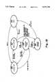
- FIG. 1is a block diagram of a Group of wired LAN segments bridged together by RF communications between communicators connected to each LAN segment in accordance with the present invention.
- FIG. 2is a block diagram similar to FIG. 1 showing the relative RF transmission ranges of a hub communicator of the Group shown in FIG. 1, and some of the other remote communicators of the Group, shown in FIG. 1.
- FIG. 3is an illustration of a communication cycle established by the hub communicator shown in FIGS. 1 and 2 to control outbound signal transmissions from the hub communicator to the remote communicators of the Group and to control inbound signal transmissions from the remote communicators to the hub communicator of the Group.
- FIG. 4is a block diagram of a communicator shown in FIGS. 1 and 2.
- FIG. 5is a block diagram of a RF modem of the communicator shown in FIG. 4.
- FIG. 6is a diagram showing components of a transfer unit which is communicated between communicators as shown in FIG. 1.
- FIG. 7is an expanded diagram of a payload of the transfer unit shown in FIG. 6.
- FIG. 8is an expanded diagram of a frame which forms a portion of the payload shown in FIG. 7.
- FIG. 9is an expanded diagram of fields of a header of the frame shown in FIG. 8.
- FIG. 10is a diagram showing the intervals occurring during an outbound portion and an inbound portion of the communication cycle shown in FIG. 3.
- FIG. 11is an expanded diagram of a portion of FIG. 10, showing transfer units and frames transmitted during the outbound portion of the communication cycle.
- FIG. 12is an expanded diagram of a portion of FIG. 10, showing the transfer units and frames transmitted by the remote communicators during their allocated transmission opportunities (Txops) in the inbound interval of the communication cycle.
- FIG. 13is an expanded diagram of a transfer unit and a frame sent by a remote communicator to the hub communicator to obtain a Txop allocation in the communication cycle.
- FIG. 14is an expanded diagram of exemplary transfer units and frames sent by hub communicators of adjacent Groups during a hub beacon interval of the communication cycle.
- FIG. 15is an operational state diagram showing the operation of the communicators shown in FIG. 1.
- FIG. 16is a flow chart of the operations occurring during listen RF active state of operation shown in FIG. 15.
- FIG. 17is a flow chart of the operations occurring during a request Txop state of operation shown in FIG. 15.
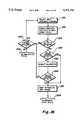
- FIG. 18is a flow chart of the operations occurring during hub communicator active state of operation shown in FIG. 15.
- FIG. 19is a flow chart of the operations occurring during remote communicator active state of operation shown in FIG. 15.
- FIG. 1A plurality of LAN segments which may be bridged in accordance with the present invention are shown in FIG. 1 and referenced at 30a, 30b, 30c, 30d, 30e and 30f.
- LAN segmentsgenerally will hereinafter be referred to by the reference number 30, while specific LAN segments shown in FIG. 1 will be referenced by an alphabetical identification in conjunction with the reference numeral 30 as shown.
- Each LAN segment 30is in actuality a LAN or at least one node of LAN.
- Each LAN segment 30includes a physical communication medium 32 which connects nodes 34 of each LAN segment 30 in a network topology (bus, ring, star, etc.) which is illustrated as a bus in FIG. 1 for simplicity.
- the communication medium 32will typically take the form of electrical connectors interconnecting the nodes 34, but may also include radiant energy links, such as modulated light links, as are known to be employed in LANs.
- Each node 34comprises a network interface 36 connected to the communication medium 32, and one or more resources 38 connected to the interface at each node 34.
- the resource 38can assume a variety of different configurations, as is known, but will typically include a computer such as a work station, portable computer, personal computer, printer, server, or the like.
- Communication between separate nodes 34 and the resources 38 on those LAN segments 30 which have multiple nodes 34 and resources 38, such as LAN segments 30a, 30b and 30e,is accomplished in accordance with a network protocol which governs the transmission and receipt of communications, known as LAN packets, over the medium 32 linking the interfaces of the nodes 34.
- the communication actuallyis undertaken by the interfaces 36 transmitting and receiving the LAN packets over the communication medium 32 to establish communication between the nodes 34.
- the form of the LAN packetsis also controlled by the network protocol which governs the communications over the LAN segments 30.
- each node 34has its own node address or NID.
- the NID of each node 34is maintained by the interface 36 associated with the node. As shown in FIG. 1, exemplary NIDs for each node are illustrated enclosed within circles within the rectangles designating each node 34.
- the LAN packets transmitted from a source nodetypically contain the address of the source node (SID) sending the packet, and the address of the destination node (DID) to which the packet is addressed, in accordance with the typical network protocol.
- Some of the LAN segmentsare single resource, single node LAN segments. Thus, it is impossible to communicate between nodes on those LAN segments because two active nodes, a source node and a destination node, are required for LAN packet communication, and two nodes do not exist on those LAN segments.
- the other LAN segmentsi.e. 30a, 30b and 30e, permit LAN functionality between the nodes 34, because each LAN segment contains at least two nodes 34.
- the preferred embodimentuses the RF MAC protocol for bridging between LAN segments, however the MAC protocol of the present invention is for communication between RF nodes.
- the communicator function 60can also be used directly as a LAN adapter, replacing the interfaces 36 of the PC or other resources 38.
- One capability of the present inventionis to bridge together the LAN segments 30, whether single node LAN segments (30b, 30c and 30f) or multiple node LAN segments (30a, 30b and 30e) so that all of the nodes 34, regardless of the type of LAN segment 30 upon which they appear, can achieve effective LAN like communication among a "Group" of separate LAN segments.
- the number of LAN segments which can be bridgedis preferably limited to a predetermined number, for example sixteen.
- the communications between the LAN segmentswill be transparent to the network interfaces 36 and without altering the protocol used on any of the LAN segments 30. In essence, the bridged LAN segments 30 establish a single logical LAN.
- communicator stations or communicators 60a, 60b, 60c, 60d, 60e and 60fare connected to each LAN segment 30a, 30b, 30c, 30d, 30e and 30f, respectively, as is shown in FIG. 1.
- Each communicatorwill hereinafter be generally referred to by the reference number 60, while specific communicators shown in FIG. 1 will be referenced by an alphabetical identification in conjunction with the referenced numeral 60 as shown.
- Another more general capability of the present inventionis to serve as a self-contained, wireless network or LAN, with the communicators attached directly to the resources 38, in place of the wired LAN segments 32 and the associated interfaces 36.
- the communicatorsdirectly connect to a resource and convey LAN packets or other information using the MAC protocol of the present invention, and no bridging between separate LAN segments occurs.
- the MAC protocol of the present inventionis equally applicable to either situation.
- Each communicator 60communicates with the node or nodes 34 on the LAN segment 30 (or resource 38) to which it is locally attached.
- a "local" node or a “local” LAN segment or resourceis the one which is directly connected by the communication medium 32 to the communicator 60 with regard to which the reference "local” is made.
- Each communicator 60preferably includes a LAN interface 36.
- the interfaces 36 in the nodes 34 and in the communicator 60are the same, and they operate in accordance with the same network protocol. Communications over the local LAN segment between communicator 60 and each node 34 occur through the interfaces 36 and the communication medium 32 in accordance with the network protocol, just the same as communications between two nodes 34 on a local LAN segment. Because the interfaces 36 associated with the communicators 60 communicate with the interfaces 36 associated with the nodes 34 under the same protocol, the interfaces 36 associated with the communicators 60 must have an NID like the other LAN interfaces 36.
- the communicators 60are not nodes 34, as that term is used to describe LAN functionality, because the communicator 60 achieves the administrative functions associated with bridging instead of the usual information processing functions associated with a resource 38.
- the communicators 60attach directly to the resources 38, the communicators 60 do function as nodes on the wireless network, and this RF network serves as the LAN, so there are not separate LAN interfaces 36 nor LAN NIDs.
- the communicators 60transmit and receive radio frequency (RF) signals known as "frames."
- the communicator 60 which sends a frameis referred to as a transmitter communicator or “transmitter,” and the communicator 60 (or communicators in the case of broadcast or multicast frames) which receives the frame is a receiver communicator or "receiver.”
- Each frameis formed by a digital bit stream containing information and/or data to accomplish the bridging functions, the LAN functions and/or the MAC protocol aspects of the present invention described below.
- the number of communicators in the Groupmay depend on their radio transmission range.
- the rangemay be limited due to government regulations limiting the amount of the power of the transmitted RF signal, by obstacles and obstructions which may block or attenuate the RF signals, and/or by interference from other, nearby transmitters, for example. Accordingly, all of the communicators may be unable to establish direct RF communications with one another.
- the communicator 60ais not within the transmission range of the communicator 60d, since the transmission range of the communicators 60a and 60d are represented by the circles 62a and 62d, respectively.
- Each communicator's transmission rangewill hereinafter be generally referred to by the reference number 62, while specific communicator transmission ranges shown in FIG.
- one of the communicators 60will function as a hub communicator or "hub” 64.
- the hub 64will act as a central receiver for the communications transmitted among the other communicators 60 of the Group.
- the communicators 60 other than the hub 64are designated as remote communicators or "remotes" 66.
- the hub 64also functions as a central relay station for relaying transmissions between the remote communicators 66 and for receiving messages from the remotes 66.
- both communicators 60c and 60fare within range of all the other communicators 60a, 60b, 60d and 60e, either would be a suitable choice for the hub 64 from the standpoint of communications range.
- communicator 60fhas been designated as the hub 64.
- the hub 64will be able to receive and relay transmissions from all the communicators 60a, 60b, 60c, 60d and 60e achieving communications between all communicators 60, including those which are not within range of each other for point-to-point or direct communications, such as communicators 60a and 60d.
- the hub 64allows for the single logical network to be larger than the transmission range 62 of a single communicator 60.
- the remotes 66need not be within transmission range 62 of each other to communicate as long as the remotes 66 are within transmission range of the hub 64.
- the single logical network formed by the hub 64 and the remotes 66represents a topology which is both a logical and a physical star.
- the physical staris found by the remotes 66 arranged around the more central hub 64, which permits the single logical network of a physical size greater than the transmission range of any one of the communicators in the Group.
- the logical starresults from the individual communication paths between the hub and each of the remotes. Signals are transmitted from the hub to all of the remotes, and from each of the remotes to the hub.
- the logical communication path for all of the transmissionsis to or through the hub, thereby establishing the star topology.
- the physical layer of the seven layer ISO reference model for data communicationsis represented by this logical and physical star topology. All physical layer communications are either bilateral transmissions between a remote 66 and a hub 64, bilateral transmissions between a hub 64 and a remote 66, or broadcast transmissions from the hub 64 to all remotes 66.
- the operation of the communicatorsemulates the characteristics of a logical bus as viewed from above the link layer of the media access control (MAC) sublayer of the link layer of the seven layer ISO reference model for data communications.
- MACmedia access control
- the physical and MAC layer functionsare implemented using the star topology.
- the hub 64controls the communications to and from the remotes, using a MAC protocol according to the present invention.
- the foundation for this MAC protocolis allocation of media access for transmission (e.g. the right to energize the RF transmitters at the respective communicators) at appropriate, non-overlapping times and media access for reception (e.g. the need to energize the RF receivers at respective communicators), at appropriate times that RF frames may need to be received.
- These timesreferred to as transmission opportunities (Txops), are controlled in the context of a communication cycle 70, shown in FIG. 3, which the hub establishes and which is repeated on a continuous basis as long as the hub is active.
- the present inventionis concerned with media access for reception as well as for transmission.
- the hubgoverns the sequence of its own frames which are contained in transfer units, transmitted outbound from the hub 64 to the remotes 66 during an outbound portion 72 of the communication cycle 70.
- the hubalso controls the sequence and duration of frames which are contained in transfer units which are transmitted inbound from the remotes 66 to the hub 64 during an inbound portion 74 of the communication cycle. It is during the outbound portion 72 and inbound portion 74 of the communication cycle 70 that all frames are communicated.
- an initial information (info) interval 76during which the hub 64 transmits control and other information to the remotes 66. This information allows each of the remotes 66 to recognize and participate in the communication cycle at the predetermined times.
- a broadcast interval 78is also included in the outbound portion 72 to allow the hub 64 to broadcast the same information to all of the remotes 66 in the Group, using a single transmission that is expected to be received simultaneously by all remotes 66.
- a directed packet interval 80is also provided to allow the hub 64 to transmit frames to specifically identified remotes 66 in the Group.
- the information communicated in the initial information interval 76is repeated in an alternative information (alt info) interval 82.
- an alternative information (alt info) interval 82By repeating the transmission of the control information in the alternative information interval 82, the chance for the remotes 66 to lose the synchronized nature of operation with the hub 64 is substantially diminished.
- frames previously transmitted from the remotes to the hub during the inbound portion of previous communication cycleare acknowledged by the hub.
- Txoptransmission opportunity
- the hub 64allocates to each remote 66 requesting one a Txop 84.
- the Txop 84simply is a position in the order of other remotes 66 which have requested Txops 84 to transmit to the hub 64.
- the Txopis an amount of time during which the remote may transmit one or more frames to the hub.
- the Txops 84are preferably allocated to the remotes 66 by the hub 64 in a predetermined order, and the hub may also vary the time durations of the allocated Txops 84, without varying their order.
- All remotesreceive a Txop 84 with (at least) a predefined minimum duration on each communication cycle 70, whether or not they have any frames to transmit.
- the hubmay adjust the duration of the Txops 86 by observing traffic patterns and in accordance with information received from each remote 66 relating to the amount of information which each remote has queued for transmission, among other factors.
- the remoteBesides using the allocated Txop to transmit frames from a remote 66 to the hub 64, the remote also acknowledges any directed frames communicated to it from the hub 64 during the communication cycle. If there is one or more outgoing frame, the remote 66 may "piggyback" these acknowledgements with these outgoing frames.
- the hub 64may determine that it is not necessary to preserve a Txop for a particular remote 66, and thereafter cancel the Txop 84 allotted to that remote 66.
- a Txop request interval 88is provided.
- communicators 60 which have recently joined the Group, or communicators 60 which have not previously been allocated Txops 84 in which to transmit messagesare allowed to transmit messages to the hub 64 requesting that they be allocated a Txop.
- the hub 64Upon receipt of the Txop request, the hub 64 will allocate a Txop 84, if any are available. The hub 64 will inform the requesting remote (and all other remotes) of this Txop allocation in the information intervals 76 and 82 of the next communication cycle.
- This dynamic allocation of Txops 84is particularly beneficial in situations where portable communicators move into and out of range of the Group's hub at arbitrary times, and should neither burden the available aggregate bandwidth of the Group with an unused Txop when it is not present nor require user intervention when it rejoins the Group.
- the communication cycle 70orders the transmission of communication control information to the remotes 66 (including acknowledgements to previous frames received from the remotes 66), allocates inbound Txops 84 in accordance with the amounts of transmission time requested by each remote (and other factors), transmits outbound frames (both broadcast and directed) to the remotes 66, and receives inbound frames from the remotes 66 pursuant to the previously-made Txop allocations.
- the remotes 66in their allocated sequence of Txops 84, acknowledge previous frames received from the hub 64, and transmit inbound frames to the hub 64.
- the remotesmay request allocation of Txops when needed during the Txop request interval 86 of the inbound portion 74.
- All intervals of the communication cycle 70take place within the limits of predesignated assigned times established by the hub. Each interval is measured in terms of a number of basic time increments (BTIs) pre-specified to all communicators in the Group.
- BTIbasic time increments
- a BTIis a predefined unit of time (parameterized, default of 4 milliseconds, for example) that is the fundamental increment of communication cycle 70 time allocation, and is the metric by which intervals within the communication cycle 70 are measured.
- the hub 64controls the duration and usage of the communication cycles 70.
- the time for the overall communication cycle 70, along with the specific interval allocations within the cycle 70,are broadcast by the hub 64 in during the information intervals 76 and 82 in the form of control information delivered in an information frame transmitted during the information interval 76.
- the remotes 66are able to determine in advance approximately when to expect frames transmitted from the hub and when to transmit frames to the hub. As a consequence of the predictable times when frames may be both received and transmitted, the remotes can power their radio interfaces down to preserve power at other times. Because radio circuits with radiated RF energy levels that comply with the rules in Part 15 of the FCC regulations consume about as much electrical power when receiving as when transmitting, this ability to power the radio off completely is a major benefit for battery-powered communicators. This MAC protocol control feature is of particular importance in facilitating portable computer attachment.
- this power down capabilitymakes it possible to obtain an increase in useful battery life of over five times compared to the battery life if the radio interface was continuously powered for reception (or transmission).
- the communication cycle features of the MAC protocolalso provides efficient, low-latency support for typical LAN usage patterns, in which frame size distribution is strongly bimodal (one mode quite short, the other mode at or near the maximum frame size for that LAN protocol), and frame arrival rates are burst like (highly non-uniform, with shifting peak traffic locations). Only those communicators which transfer frames on a regular basis are regularly allocated Txops longer than one BTI, thereby reserving bandwidth for those more active remotes. In addition the relative allocation of the time among the remotes favors those which have requested and used more time for frame transmissions in the recent past, which again keeps with the shifting peak traffic patterns of LAN-like communications.
- the hub 64serves a number of purposes, including: media access control, with specific Txops allocated to specific remotes; bandwidth allocation, in response to requests that indicate the amount of data awaiting transmission, thereby permitting adaptive allocations that favor the (dynamically changing) remotes 60 that have the most pending traffic; power management, as described; basic security, since each communicator 60 must be allocated a Txop before being able to participate in frame exchanges; MAC-layer frame acknowledgement (without a power consumption penalty), because acknowledgements can be piggybacked on subsequent frames with a known upper bound on the time delay from the original transmission attempt; and network administration, because all frames traverse the Group's hub 64.
- the communicator 60combines radio hardware, interface hardware, and the necessary firmware to implement a transparent, wireless logical network between the communicators 60.
- the communicatorspreferably transmit and receive messages over a wireless physical layer provided by a direct-sequence, spread spectrum (DSSS) radio data link.
- DSSSdirect-sequence, spread spectrum
- a half-duplex, packet-oriented transfer mediumis thereby established with sufficiently high data rate, sufficiently short transmit/receive turnaround time, sufficiently low power consumption and transceiver on/off speed, sufficiently low framing overhead requirements, and sufficiently high data reliability to support LAN-like operational characteristics between the separated LAN segments.
- the communicator 60also supports directly the logical-link control sublayer, network layer and all higher layers of communication, rendering the location-sensitive aspects of the wireless data link transparent to the attached resources.
- Each communicator 60is not a node on the local LAN segment, but is a node on the wireless network.
- Each communicator 60has a network interface 36, a microcontroller 90, a read only memory (ROM) 92, a random access memory (RAM) 94, and a RF modem 96, all of which are interconnected by a bus 98.
- the interface 36is equivalent to that used by each node 34 on the LAN segments 30.
- the attachment of the interface 36 to the bus 98 and the microcontroller 90is similar to that manner in which the interface 36 of a node 34 connects to its attached resource 38.
- the microcontroller 90in its presently preferred form, is a Motorola 68HC16 microprocessor.
- the instructions controlling the operation of the microcontrollerare stored as firmware in the ROM 92 and/or in software instructions in the RAM 94. These instructions implement the MAC protocol described herein.
- the RAM 94contains a buffer to temporarily store information used when the communicator 60 is functioning.
- the information stored in the RAM 94may be copies of LAN packets received from the interface 36 and awaiting transmission on the RF network, copies of frames received from the RF modem 96 and awaiting transmission on the LAN segment 30, or (for hub communicators) copies of frames received from one remote and addressed to another remote, awaiting transmission in an outbound interval of the communication cycle.
- the RF modem 96preferably has at least two antennas 100 and 102.
- the antennasare oriented in different configurations, to allow selection of the one which provides the best reception. Transmission of the signals usually does not require antenna selection, because signal transmission usually does not involve as many sensitive aspects as signal reception. At any physical location of a communicator, one of these antennas 100 or 102 is likely to offer better signal reception than the other. Selection of the best antenna is performed by software instructions in the RAM 94 as part of the signal acquisition process which the communicator 60 undertakes in conjunction with the receipt of RF frames.
- the time required to determine that the signal reception from one antenna is inadequate, and then to synchronize to the signal being received by the other antenna,is time during which transmissions cannot be successfully received by a communicator 60. Accordingly, the MAC protocol implementation involved in communicating the RF frames and the low-level radio control functionality in the microcontroller 90 cooperate to permit the selection of a better antenna.
- the RF modem 96accepts a digital data stream from the bus 98 at the transmitting communicator 60, produces and transmits the RF signal, and the RF modem 96 at the receiving communicator 60 receives the RF signal and produces a digital data stream corresponding to that supplied to the transmitting RF modem 96 (other than in the presence of errors due to RF interference or excessive RF signal attenuation).
- the transmitting and receiving RF modems 96perform all of the necessary spreading, modulation, demodulation, and despreading functions to successfully transfer the frames between communicators.
- the transmitting RF modem 96also generates a preamble at the beginning of each transfer unit (of one or more frames) that allows the receiving RF modem 96 to acquire and synchronize with the transmitted radio signal.
- all other data communication functionsincluding framing, formatting, address recognition, error detection, and link control, are imposed upon the physical layer digital data stream by the present invention at the MAC layer by non-RF modem hardware and microcontroller-based firmware of each communicator 60.
- the RF modemAt this MAC layer there is also a close interaction with the RF modem to achieve various control and calibration functions, including power consumption control, oscillator calibration and temperature compensation, receiver automatic gain control calibration, received signal acquisition, antenna selection for spatial diversity at the receiver; and transmitter power control (adaptive power management) associated with each communicator 60.
- Some of the calibration parameters provided by the RF modem 96may also be used by the present invention for MAC layer control purposes, as well as by the RF modem 96 itself.
- the microcontroller 90is also involved in processing the calibration parameters to calculate calibration responses to provide feedback to the radio.
- the RF modem 96 in the preferred embodimentis a Model 100 DSSS RF Modem sold by Signal Technologies, Inc. of Longwood, Fla.
- the spread spectrum productoperates a 191,176 baud, with a chip rate of 3.25 MHz at 17 chips per baud.
- the RF modem 96is preferably programmed to operate on any or all four, non-overlapping frequency channels within the 902 to 928 MHz ISM frequency band defined by FCC rules.
- This RF modem 96can support either binary phase-shift keying (BPSK), which achieves 1 bit/baud (for a data rate of 191 Kbps); or quadrature phase-shift keying (QPSK), which achieves 2 bits/baud (for a data rate of 382 Kbps).
- BPSKbinary phase-shift keying
- QPSKquadrature phase-shift keying
- the BPSK functionallyis identical to the QPSK functionality, other than for the data rate (half as fast), and synchronization time.
- the digital interfacing functions (spreading codes, etc.) and frequency synthesizer interfacing functions (frequency channels)are programmed in an identical manner for both BPSK and QPSK operation.
- One additional major differenceconcerns the calibration details, which must usually be separately established for each type of operation but in a manner that is independent of the MAC protocol that is the subject of the present invention.
- the RF modem 96is shown in FIG. 5.
- the RF signalsare transmitted from or received by antennas 100 and 102.
- a switch 103controlled by the microcontroller 90, selects one of the (two or more) available antennas.
- the transmitted and received signalspass through a conventional RF filter 104.
- a selection switch 106controls the signal path through the filter 104 and antennas 100 and 102. In one switch position illustrated in FIG. 5, signals are received. In the other switch position, the signals are transmitted.
- the switchis a gallium arsenide field effect transistor (FET) switch. When not transmitting, the selection switch 106 is set to accept incoming signals.
- FETgallium arsenide field effect transistor
- the received signalspass through the filter 104 and are applied to a low noise amplifier 108.
- the low noise amplifier 108amplifies the signals and supplies them to another filter 110.
- the signals from the filter 110are applied to a radio device 112 which performs both a radio receiving function as well as an amplifying function. Signals from the radio device 112 are applied to a coherent demodulator 114.
- the coherent demodulator 114extracts the base band data from the RF carrier signal which has been BPSK or QPSK modulated.
- the coherent demodulator 114also functions as a coherent correlator for the spread spectrum sequence which modulates the data.
- a control signal for the coherent correlation or spread spectrum sequencing functionis obtained from a spread spectrum controller 116.
- the coherent demodulator 114includes a base band automatic gain circuit (AGC) which keeps the signal levels predictable when the AGC signal is applied to the radio device 112.
- AGC circuitalso forms part of a delay locked loop which interacts with the spread spectrum controller 116 during demodulation.
- a band gap reference signalis also supplied by the coherent demodulator 114 for use by other components.
- the coherent demodulator 114includes comparators to establish digital waveforms and provide in-phase and quadrature phase data outputs in a form compatible with the other digital components of the communicator.
- the coherent demodulatorresponds to the magnitudes of the in-phase, base-band and quadrature phase components of the received signal to establish a received signal strength indication (RSSI) signal representing the energy of the received demodulated signal.
- RSSIreceived signal strength indication
- the functionality of the coherent demodulator 114is conventional and appreciated by a person having skill in the field of signal communications. For convenience, all of these functions are readily available on a single commercial integrated circuit designated as CSL-100 available from Signal Technologies, Inc. of Longwood, Fla.
- the spread spectrum controller 116is the ability to rapidly acquire and synchronize with incoming received signals.
- the ability of the spread spectrum controller 116 to quickly acquire and synchronize with received signalsmay be advantageously achieved by employing the techniques described in U.S. Pat. No. 4,649,549.
- the spread spectrum controller 116is a commercially available integrated circuit, having a designation AS-100, available from Signal Technologies, Inc. of Longwood, Fla.
- the components of the spread spectrum controller 116include a timing distributor 118 which responds to a signal from an external clock oscillator 120 and distributes clock timing signals throughout the sections of the spread spectrum controller 116.
- One of the major sections of the spread spectrum controller 116is an interface 122, which allows the exchange of control and data signals over the communicator bus 98 with the other components of the communicator 60.
- Internal program registers 124allow settings to be recorded therein through the interface 122 to configure the functionality of the spread spectrum controller 116 in many respects, for example to establish the polynomial sequence used in spreading and despreading the signals, controlling certain other elements in the RF modem 96, selecting the type of modulation, maintenance functions and the like.
- the interface 122is connected to an internal bus 126, and most of other components of the controller 116 are also connected to the internal bus.
- a transmitter/receiver (Tx/Rx) power control 128controls a number of elements within the RF modem 96 so that they can be properly power managed by selectively powering them down to save battery power, for example, if the communicator 60 is powered from a battery.
- a spread spectrum generator and encoder 131is a programmable device that allows for the implementation of a Galois polynomial sequence generator.
- An in phase, I-transversal filter 132 and a quadrature phase Q-transversal filter 134receive signals from the spread spectrum generator and encoder 131 prior to RF modulation for transmission.
- a spread spectrum correlator and decoder 130handles the demodulator 114 output to regenerate the unspread data.
- a baud synchronizer 136allows a signal to be obtained which references to the data clock of the received data.
- the spread spectrum correlator and decoder 130preferably employs the technology described in U.S. Pat. No. 4,649,549.
- a synthesizer interface 138delivers signals to an RF synthesizer 140 which generates the various signals applied to the radio device 112 to down convert signals from the RF band and to up convert signals from the communicator 60 and spread spectrum controller 116, in the case of received signals or transmitted signals, respectively.
- the spread spectrum controller 116accepts data through the interface 122, translates the data from parallel to serial four and applies the appropriate spreading sequence to the data so that it becomes a base band spread spectrum signal. This information in spread spectrum form is applied to the radio transmitter 142 where it is converted to the appropriate RF band. The radio transmitter 142 applies the RF signal through the selection switch 106 and the filter 104 to the selected one of the antennas 100 and 102 where it is transmitted.
- the communicators 60dynamically perform frequency channel selection upon initialization, with the objective of minimizing interference between Groups that have overlapping RF communication spaces. If Groups are assembled using multiple hubs 64 which support inter-hub handoffs, the frequency channels may be statically assigned to each hub in order to provide repeatable handoff performance.
- the present inventioncan be extended to provide wireless network communication for a wider physical area by providing a plurality of communicators predesignated as hubs all configured as part of the same Group and able to communicate with each other via a common (preferably high speed) wired "backbone" network.
- a portable communicatorthat leaves the transmission space 62 of one hub of the Group, but entered the transmission space 62 of an adjacent hub in the Group (generally operating on a different frequency channel to avoid interference at the region of overlap) will detect the second hub during the attempt to detect an active hub after losing contact with the first hub.
- this other hubis detected, by virtue of its being part of the same Group, and sharing a common backbone network over which the plurality of hubs can exchange LAN packets, the remote can remain in communication as part of the same logical network as soon as that remote has obtained a Txop allocation from the second hub.
- This type of microcellular functionalitycan be implemented upon the remote communicators attempting to re-establish communication with a hub (termed “passive handoff” because the hubs do not play an active role in the process) or by negotiation between the adjacent hubs when the RSSI level drops below a predetermined threshold (termed “negotiated handoff” because the hubs initiate the process of checking the relative signal strengths and determine the best destination hub for the handoff).
- the RF modems 96can be programmed to use any one of a large number of spreading sequences (for example several thousand spreading sequences), each of which is referred to as a code. All members of a Group of communicators 60 must be programmed to use the same code in order to achieve successful communication. Communicators 60 operating in the same RF communication space, and using the same frequency channel but a different spreading code than the Group members, cannot receive transmissions from other communicators of the Group, and transmissions by such other communicators may interfere with RF communication among the Group members. The potential for such interference can be reduced, but cannot be eliminated, by selection of spreading codes with adequate Hamming distance from each other. Accordingly, a limited subset of the available code space, for example 1000-4100 codes, selected based on appropriate Hamming distances, will be used to minimize the risk of inter-Group interference and to maximize the degree of communication security provided by the spreading.
- a code spacefor example 1000-4100 codes, selected based on appropriate Hamming distances
- the spreading sequence codesform the basis for a level of communications security because unless a communicator 60 is utilizing the appropriate code, it cannot participate in the communications. Certain codes may be also reserved for special network control and diagnostic purposes.
- the code usageis identified by code identification numbers that are used to index tables within the communicator ROM 92 or RAM 94 that contain the specific multi-byte sequences needed to program the RF modem to generate these codes.
- the potential for interference between adjacent Groupsis further reduced if each transmission by a communicator 60 uses the minimum level of RF energy required to achieve the needed signal strength at the designated receiving communicator 60. Reducing transmitted power may also improve the battery life of battery-powered communicators 60 by possibly consuming less power during typical transmissions.
- the ability to measure the received signal strength (RSS) at each end of a communication activity, plus the inclusion of a received signal strength indication (RSSI) parameter in certain frames communicatedpermits this type of adaptive management of transmitted power. Subsequent transmissions to a communicator that has reported excessively high RSSI values can be made using reduced transmit power. If RSSI levels are later reported to have dropped below a predetermined threshold, transmit power can be increased to compensate.
- the digital data streams provided to the sending RF modem 96are included in transfer units 144, one of which is illustrated in FIG. 6.
- the transfer unit 144includes three components: a preamble 146, a payload 148 and a postamble 150.
- the preamble 146is a predetermined sequence of binary values which are used by receiving communicators 60 to acquire and synchronize to the incoming transmission.
- the preamble 146provides the necessary amount of time with known information content for the demodulation and despreading functions of the RF modem 96 to acquire and synchronize with the signal prior to the beginning of the payload 148.
- the preamble 146consists of a sequence of alternating ones and zeros lasting at least 1 millisecond.
- the length of the preamble 146may be defined separately for various types of transfer units 144.
- transfer units 144 containing information frames, which are vital to maintaining the integrity of communicationsa longer preamble 146 is generally used to provide a greater probability of acquiring the incoming signal, and to allow switching to the alternate antenna with enough preamble remaining to acquire and synchronize via the alternate antenna if RSSI levels through the first antenna prove insufficient.
- the preamble 146 for transfer units containing control information and hub beacon frames sent during the communication cycleis also generally longer than the minimum requirement to permit an alternate antenna to be selected midway through reception of the preamble 146 and still allow time for the RF modem 96 to synchronize to the signal using the alternate antenna.
- a shorter preamble 146is used because an error in a data packet frame will not impact communications to the same extent as an error in a control or information frame, and the use of longer preambles on such transfer units would increase network overhead.
- the default values for the length of the preamble 146are 192 bytes for transfer units 144 containing information frames, 96 bytes for transfer units containing control frames, and 48 bytes for transfer units 144 containing neither control nor information frames.
- the preamble 146is generated by the RF modem 96 of the transmitting communicator 60, is used by the RF modem 96 of the receiving communicator for signal acquisition and synchronization, and is detected and discarded by the microcontroller and its related circuitry of the receiving communicator 60.
- the postamble 150marks the end of the transfer unit 144, and provides time (with RF signal activity) following transmission of the payload 148 that may be needed for the receiving communicator to complete successful reception of the payload 148 prior to cessation of RF signal activity.
- the postamble 150also provides a period of non-communication of sufficient duration to prevent destructive interference from overlap between transfer units 144 transmitted by different communicators. This non-communication period compensates for the allowable degree of timekeeping uncertainty that can accumulate between communicators 60 in the Group during any communication cycle 70.
- the postamble 150is generated by firmware in the microcontroller 90 of the communicator 60, and its length is a predetermined constant to ensure a minimum separation between transfer units 144.
- the payload 148 of the transfer unit 144carries the substance of the communication. No restrictions are imposed by any of the components of the RF modems 96 on the contents or format of the payload 148.
- the payload 148 of each transfer unitwhich is shown in FIG. 7, is a sequence of one or more frames. Frames are the fundamental data transfer entity of the present invention. Each transfer unit comprises one or more frames 152 separated by inter-frame gaps 154. The frames 152 contain the substantive information transmitted in the transfer unit.
- the number of frames in any transfer unitis limited by the lesser of the amount of information to be sent by the communicator 60, or for inbound communications from remotes 66 to the hub 64, the maximum amount of time allocated to the remote by the hub 64 for use as a Txop in the current communication cycle. If the allocated Txop is insufficient to send all queued, outgoing frames, some number of complete frames will remain unsent at the remote until another Txop occurs in a subsequent communication cycle 70. Frames 152 are never split up in different transfer units.
- inter-frame gapsWhen multiple frames 152 are sent in a single transfer unit, these frames 152 are sent in direct succession, separated by inter-frame gaps (IFG) 154.
- the IFG 154provides a sufficient amount of time for the receiving communicator 60 to complete handling of the preceding frame 152 and to prepare for receipt of the following frame 152.
- Each transfer unitthus contains an integral number of frames 152 and an integral number of IFGs 154 which is equal to one less than the number of frames 152.
- the IFG 154is generated by the microcontroller 90 of the transmitting communicator 60 and is discarded by the microcontroller 90 of the receiving communicator 60.
- Each frame 152has the same basic format, one of which is shown in FIG. 8. Each frame is formed by five fields: a starting flag 160, a header 162, a body 164, an ending flag 166, and a cyclic redundancy check (CRC) 168.
- a starting flag 160a header 162
- a body 164a body 164
- an ending flag 166a cyclic redundancy check 168.
- CRCcyclic redundancy check
- the starting flag 160is a unique bit pattern that identifies the beginning of a frame 152.
- the starting flag 160is generated under firmware control of the transmitting communicator 60 during frame transmission, and is detected by firmware or hardware at the receiving communicator 60 during frame reception.
- the starting flagis unambiguous, so that no other sequence of bits in any transfer unit has the same pattern. This avoids the risk of commencing frame reception based on an arbitrary data byte in the middle of a body field.
- the starting flag 160is six ones, preceded and followed by a zero.
- This valueis distinct from the preamble 146 (alternating ones and zeros), the postamble 150 (all zeros), the IFG 154 (all zeros) and the ending flag 166 (seven ones preceded by a zero).
- the uniqueness of the starting flag valueis assured without restricting the use of any data values within the header 162 and body 164 fields of the frame 152 by "bit stuffing" within frames.
- Bit stuffingis a technique that renders a predefined pattern of bits unambiguous by inserting bits at defined locations in an outgoing bit stream. The inserted bits prevent a predetermined bit pattern from occurring in locations other than those desired. Bit stuffing is commonly used, as it is in this situation, to render unique the delimiters of the frame boundaries.
- the portions of the frame 152 subject to bit stuffing in the frame shown in FIG. 8are the header 162 and the body 164 fields. These fields are made unique by detecting when sequences of five or more one-bits that occur in the raw data that makes up these fields, and to insert (“stuff") a zero after any such sequence of five successive one-bits.
- the starting flag 160 and ending flag 166include six and seven successive one bits, and because zero bits are stuffed after all other sequences of five successive ones in the other fields, the bit patterns of the starting flag 160 and ending flag 166 are unique within the transfer unit. In cases where variable amounts of transmission time are not desirable, a higher-overhead but fixed-length form of bit stuffing is to insert a zero bit after every fifth data bit in the header and body fields of the frame.
- bit stuffingWhen bit stuffing is employed as part of frame transmission, "bit stripping" must be performed as part of frame reception. Bit stripping is the inverse operation to bit stuffing, thereby restoring the original bit pattern to the received data stream. Typically bit stuffing and bit stripping are collectively referred to simply as “bit stuffing.” Bit stuffing is performed under control of the microcontroller 90 at the transmitting communicator 60 and bit stripping is performed under control of the microcontroller 90 at the receiving communicator 60.
- the header 162includes a number of fields which are described in conjunction with FIG. 9.
- the fields of the headercontain several components of information which describe the structure and content of the frame 152.
- the first field in the header 162is an organizationally-unique identifier (OUI) 172, which is three bytes in the preferred embodiment.
- the OUI 172is a constant value which is globally unique to the manufacturer of the communicator 60 and is preferably the identifier assigned to that manufacturer by the IEEE project 802 for LAN standardization.
- the primary operational purpose of the OUI 172is that its value can be treated as a constant for further qualifying the validity of frame reception, shortly after detection of the starting flag 160 (FIG. 8).
- the OUI 172is followed by a communicator destination address or identification (CDID) field 170 which specifies the communicator 60 to which the frame 152 is directed, or a predetermined bit pattern which signifies that the frame is a broadcast intended for all communicators 60.
- CDID 170is 3 bytes in the preferred embodiment.
- the address or identification (ID) of each communicator 60may be uniquely established in many different ways, such as by allocating a unique serial number to each one manufactured.
- the OUI 172 and the CDID 170constitute a standard, 48-bit, IEEE 802 compatible network address. Because the OUI 172 is unique, if a frame 152 having an unanticipated OUI 172 or CDID 170 is received, the receiving communicator 60 is alerted that the transmission came from an invalid source and should be disregarded, or that there was a transmission error and the transmission should not be acknowledged so that the transmission will be repeated.
- the low-order bit of the OUIis set to zero for directed frame addresses and is set to one for broadcasts and multicast addresses. When used in the preferred embodiment, multicasts are not needed and broadcasts are indicated by the low-order OUI bit set to one and the CDID set to all zeros.
- the communicator source address or identification field (CSID) 174follows the CDID 170, denoting the transmitting communicator 60.
- the CSID 174contains the unique ID of the source or transmitting communicator 60 which sent the frame 152.
- a frame type field 176which contains a code that identifies the usage of the information in the body 164 (FIG. 8) of the frame 152.
- Frames 152 received successfully that have unrecognized frame type codesare acknowledged by the receiving communicator 60, but the contents of the body 164 of such frames 152 are ignored.
- the types of frames 152 which valid codes in the frame type field 176include, Txop request frames, Txop grant frames, Txop relinquish frames, initial or primary information frames, basic control frames (which have no body 164), alternate information frames, hub handoff request frames, hub handoff acknowledgment frames, hub beacon frames, hub beacon reply frames, data packet frames from the hub to the remote(s) and data packet frames from a remote to the hub.
- a sequence number field 178occurs next in the frame 152.
- the sequence number 178is a counter value which is incremented every time a communicator 60 sends a frame 152.
- the sequence number 178allows the receiving communicator 60 to specify which frame (or frames) 152 needs to be resent in the event a transmission error or other problem.
- the sequence numberis incremented by 1, modulo-256, after every frame 152 transmitted by a communicator 60.
- Frame acknowledgements and retransmission requestsare based on this sequence number, so no more than 255 unacknowledged frames 152 must be permitted to be outstanding at any time. Retransmissions of unacknowledged or negatively acknowledged frames reuse the same sequence numbers as the original frame being retransmitted.
- Remotes 66maintain one sequence value which is used and incremented for each transmitted frame 152.
- Hubs 64maintain sequence number values for the maximum number of communicators 60 allowed in the Group. One of these sequence values is used for information frames, outgoing broadcast data packet frames, and beacon frames, and the other sequence values are used for directed frames transmitted to each of the remotes 66 with allocated Txops.
- An ending frame number field 180follows the sequence number field 178.
- the ending frame number field 180is used in frames 152 sent from remotes 66 to hubs 64 to acknowledge the successful reception of a contiguous block of sequenced frames from the hub 64.
- the value in the ending frame number field 180is the highest (e.g., modulo-256 with wrap-around) sequence number value of all successfully received frames 152 up to the latest sequence number that has been successfully received.
- the ending frame number field 180is not used in frames 152 sent from hubs 66 to remotes 64, because frames 152 sent by remotes 66 to the hub 64 during the inbound portion 74 of the communication cycle 70 (FIG. 3) are acknowledged in the information frame sent by the hub 64 to the remotes 66 during the information interval 76 of the outbound portion 72 (FIG. 3) of the next communication cycle 70.
- These acknowledgements in the information frameuse the same format as this field (ending frame number).
- a missing frame number field 182follows the ending frame number field 180.
- the missing frame number fieldis used in frames sent from remotes 66 to hubs 64 to indicate exceptions to the reception status reported in the ending frame number field 180.
- the primary usage for the missing frame number field 182is in cases where a Group of frames 152 in a transfer unit 144 has been successfully received, with the exception of one frame 152 somewhere prior to the end of the transfer unit.
- the ending frame number field 180reports the sequence number of the last frame 152 within the transfer unit which was successfully received, and the missing frame number field 182 reports the sequence number of the single frame 152 prior to the reported last frame that was received in error.
- both the ending frame number field 180 and the missing frame number field 182contain the same value (the sequence number of the last successfully received sequence of frames with no preceding erroneous frames).
- the missing frame number field 182is not used in frames 152 sent from hubs 64 to remotes 66, because frames sent from remotes 66 to the hub 64 during the inbound portion 74 (FIG. 3) of the communication cycle 70 are acknowledged in the information frame sent by the hub 64 to the remotes 66 during the information interval 76 of the outbound portion 72 of the communication cycle 70. These acknowledgements in the information frame use the same format as this field (missing frame number).
- a bandwidth allocation request (BWAR) field 184occurs next in the header 162.
- the BWAR field 184is used in frames 152 sent from remotes 66 to the hub 64 to indicate the amount of time needed to transfer all packets queued for transmission at that remote 66.
- the request valueis in units of basic time increments (BTIs).
- BTIsbasic time increments
- the value in the BWAR field 184is zero if there are no queued packets awaiting transmission, and is 255 if 255 or more BTIs are needed to transmit the queued packets.
- the BWAR field 184is not used in frames 152 sent from hubs 64 to remotes 66, because all bandwidth allocation decisions are made at the hub 64.
- a bandwidth request flag (BWRF) field 186follows the BWAR field 184.
- the BWRF field 186contains additional status information pertaining to the requested bandwidth allocation for frames to be sent from remotes 66 to hubs 64. This field is not used in frames 152 sent from hubs 66 to remotes 64, because all bandwidth allocation decisions are made at the hub 64.
- Codes used in this fieldsignify, for example, whether any frames have been waiting for transmission for more than two communication cycles 70 for reasons other than retries due to negative acknowledgement, whether any of the frames awaiting transmission are retries, whether the remote 66 is within a predetermined threshold of exhausting the amount of buffer memory available to hold frames queued for transmission, whether packets are queued from more than two different nodes 34 on the remote's directly-attached LAN segment 30, and whether any broadcast frames are queued for transmission.
- These flagsprovide information useful to the hub's bandwidth allocation process, especially in cases where the network is saturated and not all bandwidth allocation requests can be granted.
- the next fieldis a body length field 188 which signifies the length of the body field 164 (FIG. 8) of the frame 152.
- the code in the body length field 188is an unsigned integer that indicates the number of data bytes in the body 164 of the frame 152. This value includes all bytes from the first byte following the header 162 (FIG. 8) to the last byte before the ending flag 166 (FIG. 8), and does not include any bytes in the header 162, starting flag 160, ending flag 166 or CRC field 168. Bits added by the bit stuffing (if any) are not counted in this length because they are added during transmission after the frame is formatted and are stripped at reception before the frame's fields are processed.
- the minimum body lengthis zero (for basic control frames), and the maximum body length is defined by the maximum number of bytes in the longest allowable frame, which is 1536 bytes in the preferred embodiment.
- a calibration parameters field 190is used to transfer calibration parameter information between communicators 60.
- the values in this fieldreflect the current readings for autonomous parameters, such as temperature, or the values during the last frame 152 received from the other communicator 60 for receive-specific parameters, such as RSSI.
- values for the various parameters mentioned herein to secure proper operation of the RF modem 92may be contained in the calibration parameter field 190.
- the firmware at a communicator supporting the functionality of the RF modemmonitors a plurality of calibration parameters supplied by the RF modem, and generates corresponding calibration responses to ensure proper transmitting and receiving operation whenever the RF modem is active.
- the aspects of the calibration activities that are visible at the protocol levelinclude the need to communicate certain of the calibration parameters to the partner communicator in frame headers 162, the need for hubs to maintain separate calibration response values for each of the remotes that are currently active, and the need for a newly-active remote to conduct a signal acquisition procedure prior to requesting a Txop allocation from a hub.
- the information that is available from the calibration process that may be usedincludes an RF AGC loop parameter which provides information regarding the level of received RF energy from another communicator on the same frequency channel, whether or not that communicator is using the same spreading code; and a received signal strength indicator (RSSI) parameter which describes the strength of the demodulated, despread received signal.
- RSSIreceived signal strength indicator
- calibration parametersinclude a Costas loop parameter, a RF synthesizer loop parameter, a temperature for the oscillator circuitry of the RF modem, an in-phase signal (I magnitude) parameter, a quadrature phase signal (Q magnitude) parameter, and a delay locked loop (DLL) parameter.
- Calibration parameter responsesinclude: a Costas loop preset value, a RF synthesizer loop preset value, a RF AGC loop preset value, a RF oscillator bias value, a delay locked loop bias value, a baseband AGC preset value, a baseband AGC reference value, and a RF AGC reference value.
- the signal acquisition responsesinclude one used to select between the two available antennas of the RF modem, two used to enable information for controlling the usage of the preset calibration parameter values by the RF modem circuitry and two weighting controls used to distinguish signal acquisition (during the preamble) from normal reception.
- the body 164 of the frame 152follows the header 162.
- the bodycontains information specific to the particular frame type identified in the type field 176 (FIG. 9) of the header 162.
- the bodywill be an encapsulated LAN packet from the LAN segment 30 that is being bridged by the communicators 60 or a LAN packet directly from the attached resource in cases where the communicators are being used as network adapters rather than as bridges.
- the contents of the body 164provide control information to communicators 60 receiving the frames.
- An ending flag 166follows the body 164 of the frame 152 and, similar to the starting flag 160, the ending flag 166 is a unique bit pattern that provides unambiguous identification of the end of a frame 152.
- the value of the ending flag 166is represented by seven consecutive one bits preceded by a zero bit and, thus, is distinct from the preamble 146 (alternating ones and zeros), the postamble 150 (all zeros), the IFGs 154 (all zeros) and the starting flag 160 (six ones preceded and followed by zeros).
- the uniqueness of the value of the ending flag 166is guaranteed without restricting the use of any data values within the header 162 or body 164 fields of the frame 152 by bit stuffing within the header 162 and body 164 fields of the frame 154.
- the ending flag 166is generated by the transmitting communicator 60 during frame transmission, and is detected by the receiving communicator 60 during frame reception.
- the last field of the frame 152is a cyclic redundancy check (CRC) field 168.
- the CRC field 168provides for the detection of communication errors in the physical transmission by providing a CRC word generated by the transmitting communicator and checked by the receiving communicator 60.
- the value in the CRC field 168covers all bytes from the first byte after the starting flag 160 through and including the ending flag 166. Cyclic redundancy checking is known in the art, but in the preferred embodiment, the CRC value is calculated by the polynomial x 16 +x 15 +x 2 +1, also known as CRC-16.
- the CRC logic in the communicators 60is designed in a manner that the CRC remainder value is zero after reception of an error-free frame.
- the four types of framesare information frames, control frames, data packet frames and beacon frames.
- Information framesare used to broadcast communication cycle control information from the hub to the remotes.
- Control framesare used for bilateral transfer of protocol control information between communicators.
- Data packet framescontain substantive data, such as the LAN packets which are being bridged between LAN segments 30 or transferred between nodes 34 by the communicators 60.
- Beacon framesare transmitted by hubs 64 so that adjacent hubs can detect each other's presence. Each of these four types of frames is described in detail below.
- a primary information frameis transmitted during the information interval 76 of the communication cycle 70 shown in FIG. 3.
- An alternate information frameis transmitted during the alternative information interval 82 of the communication cycle.
- the primary and the alternate information framesare identical and are described below.
- the portions of the information frames which specify usage during the broadcast interval 78 and the directed interval 80will be meaningless if a remote first successfully receives the alternate information frame during the alternative information interval 82, because the broadcast and directed intervals will have passed before the information is available.
- communicators which only receive the alternate information framemust ignore the information relating to the broadcast and directed intervals of the communication cycle.
- the frame type field 176(FIG. 9) contains a value which distinguishes it from the other types of frames.
- the body field 164 (FIG. 8) of the information framecontains all of the information needed by remote communicators to participate in communication in accordance with the communication cycle 70 shown in FIG. 3.
- the body field of an information frameincludes a number of different fields which provides information describing each of the following types of information: (1) the number of Txops 84 which are currently allocated; (2) a security level established for the communication with the Group, for example, to allow any communicator to join or leave the Group, to limit the size and participants of the Group to a predetermined number or to predetermined ones of communicators, or the like; (3) acknowledgement (ending frame number/missing frame number) information to each remote communicator which has been allocated a Txop; (4) the number of BTIs in the present communication cycle; (5) the number of BTIs in the next communication cycle; (6) the number of BTIs in the communication cycle after the next communication cycle; (7) the number of BTIs for the broadcast interval 78; (8) the number of BTIs from beginning of the present communication cycle to the transmission time of for any directed packets sent during the directed interval 80 to each remote which has been allocated a Txop, including a code for remotes which have allocated Txops but for which the hub
- the various information in the body of the information frameprovides the remote communicators with the basis for their RF communication activities for the remainder of the communication cycle. Of special significance are the various items that define the starting times and durations of the subsequent intervals of the present communication cycle and the lengths of the next two communication cycles.
- the information framein addition to conveying the information described above, also provides the information by which the remotes remain synchronized with the hub for the purposes of turning their RF transmitters and receivers on and off.
- the start of the information frame(or alternate information frame if the remote is unable to successfully receive the information frame) serves as the datum from which the starting times of all other intervals within the communication cycle are measured.
- Each remote communicatoruses an internal clock, maintained by its microcontroller 90, to measure times until significant events (such as the expected arrival of frames to be received from the hub and the start of the allocated Txop) relative to the time that the information frame was received.
- significant eventssuch as the expected arrival of frames to be received from the hub and the start of the allocated Txop
- the importance of correct measurement of those timesnecessitates frequent resynchronization of the remotes to the sense of time promulgated by the hub. This is because the clock oscillators on each of the communicators will necessarily will operate at slightly different speeds, so the time measurement on these communicators will "drift" apart the longer it has been since they were last synchronized.
- quartz crystalsprovide oscillators that are accurate to ⁇ 0.01%, which can result in up to 100 microseconds of clock drift per second.
- a reasonable goal for inter-communicator synchronizationis not over 10% of the BTI duration.
- the BTIis 4 milliseconds, so that the permissible clock skew is 400 microseconds, allowing communication cycles up to about 2 seconds in total length.
- This upper bound on the length of the communication cycledefines the worst case uncertainty as to when receivers must be enabled to be sure to be active in time to receive expected transmissions. By re-synchronizing all communicators in the Group sufficiently often, this uncertainty can be kept small enough to avoid reducing network throughput due to extremely long delays to combat timing uncertainty.
- each remoteFor each interval within the communication cycle of interest to a particular remote, the remote must measure the time, from receipt of the information (or alternate information) frame until the interval of interest, using the appropriate count of BTIs from the body of the information (or alternate information) frame.
- Each remotemay make autonomous decisions about whether to disable or power down portions of its circuitry based on its own power consumption characteristics, power supply characteristics (AC vs. battery, amount of battery charge remaining, etc.), and the amount of time between events of interest.
- each active remotemust attempt to receive each information frame, and must attempt to receive the alternate information frame whenever it is unable to successfully receive the information frame, for a given communication cycle.
- control framesinclude a basic control frame, a Txop request control frame, a Txop grant control frame, a Txop relinquish control frame, a hub handoff request control frame, and a hub handoff acknowledgement control frame. Each is described below in greater detail.
- the basic control frameis used by remotes for non-piggybacked acknowledgements (acknowledgements to outbound directed frames when there are no inbound frames on which to piggyback these acknowledgements), bandwidth requests when the allocated Txop is too short to accommodate any of the messages which it has queued for transmission, and to prevent the loss of the allocated Txop due to inactivity when no LAN traffic is occurring on its attached LAN segment.
- the basic control frameutilizes the header field 162 (FIG. 8) with a zero-length body field.
- the acknowledgement and bandwidth request fields in the headerordinarily contain non-null information.
- Each remote in the Grouprequests a Txop allocation from the hub when that remote becomes active or enters the communication space of the hub. Each remote must obtain a Txop allocation prior to engaging in data communication over the RF network.
- a Txopwill be allocated by the hub on the next communication cycle unless all available Txops are in use.
- a Txop 84(FIG. 3) is a fixed position in the order of Txops within the inbound interval 74 (FIG. 3), but a Txop is not a fixed amount of transfer bandwidth on any particular communication cycle. The hub allocates Txops to remotes in the order Txop requests are received.
- a remoteOnce allocated, a remote retains its Txop until relinquished explicitly by a control frame from the remote to the hub or until relinquished implicitly from non-usage by the remote for a predetermined number of communication cycles.
- the maximum number of Txops which can be allocated by a hubis the maximum number of concurrently operable remote communicators in the Group. In the preferred embodiment, using RF modems with a 382 Kbps data rate, a reasonable maximum size is 16. With higher-speed RF modems, the number can be greater.
- the Txop request frameis used by newly active remotes to request a Txop allocation from the hub. Since the remote does not have a Txop in which to send this request, the Txop request frame is sent in the Txop request interval 86 (FIG. 3). This interval occurs immediately after the completion of the last of the inbound Txop communication cycle.
- Sending the Txop request control frame in the described manner during the Txop request interval 86may result in successful communication between the remote and the hub, or may result in a destructive collision if multiple remotes are sending Txop request frames simultaneously. If the hub fails to respond with a Txop grant control frame (either positive, allocating a Txop, or null, indicating the unavailability of any Txops) within a predetermined number of subsequent communication cycles, the remote will repeat the Txop request frame after expiration of a random number (e.g., one to eight) of communication cycles. By retrying at random intervals, the probability of repeated collisions among multiple, concurrent requesters is reduced to an acceptably low level.
- a random numbere.g., one to eight
- the response of the hub to the Txop request framemay be a hub handoff request frame in cases where the hub arbitration fields of the Txop request frame indicate to the active hub that the new communicator sending the Txop request frame is a better choice to be the network hub.
- the Txop request control frameutilizes a number of fields in the body 164 (FIG. 8) to convey the information necessary for performance in accordance with the present protocol.
- the body of the Txop request frameincludes fields containing codes which convey the following types of information describing the characteristics of the communicator sending the Txop request frame: (1) hub arbitration information describing whether the communicator is operating on AC power or battery power; (2) whether the communicator is configured to operate as a hub; (3) whether any resource on the communicator's directly attached LAN segment 30 is a network server; (4) the number of active nodes on the directly attached LAN segment 30; (5) the name of the Group (to permit detection of name conflicts between Groups); and the name of the communicator (assigned by the user) to facilitate network statistics gathering and administration.
- the Txop grant control frameis generated by the hub in response to a Txop request frame received by the hub during a previous communication cycle.
- the Txop grant framealso utilizes the body of the frame to hold a field containing a code indicating the transmission Txop number which the hub has allocated to the remote communicator sending the Txop request frame.
- a Txop number of zeroindicates denial of the Txop request.
- the Txop relinquish control frameis sent by a remote to the hub to indicate that the remote sending the Txop relinquish control frame will cease using its allocated Txop. This information is communicated solely by the header of this frame, so the body length field is zero.
- the hub handoff request control frameis sent by the existing hub to a remote which the hub has determined is more suitable for acting as the hub for the Group.
- the hub handoff request frameis a request that the remote communicator addressed by this frame accept responsibility as the hub and to thereafter control communications by managing the communication cycles.
- the hub which sends the hub handoff request framewill have determined that the remote to which the this request is addressed is better configured to serve as the hub, based on the hub arbitration information contained in the Txop request frame previously sent by the communicator as compared to its own hub arbitration information, contained in its information frame.
- the hub handoff request control frameincludes a sufficient number of fields in its body to convey the request and other information needed by the remote to accomplish the handoff of hub operation. This information includes various traffic and calibration parameter values.
- the handoff acknowledgement control frameis sent by the remote to the hub in response to the receipt of a hub handoff request frame.
- the handoff acknowledgement frameindicates the fact that the remote will become the hub or the rejection by the hub of the handoff request.
- the data packet frameis employed to convey network data in the body field of the frame.
- the data for the body of the data packet frameis usually a LAN packet being bridged to or from the local LAN segment or a LAN packet from the attached resource in cases where the communicators are serving as LAN adapters rather than network bridges.
- Directed data packet frames sent from a remote to a hubare addressed to the destination communicator (CDID).
- Broadcast data packet framesare sent by a remote to the hub when the hub is to retransmit the data packet frame as a broadcast or a multicast to all communicators in the Group.
- the CDID of a directed packet frame sent by a remoteis that of the hub if the ultimate destination is to a node on the local LAN segment directly connected to the hub.
- the CDID of a directed data packet frame sent by a remote to the hubis that of another remote communicator if the ultimate destination is to a node on another remote LAN segment and the hub is only to serve as a frame repeater in conveying the data packet frame to its ultimate destination.
- the source address (CSID) of the data packet frame sent by a remote to the hubis always the ID of the remote. For data packet frames sent by the hub to a remote, these frames are addressed to the remote destination communicator, or if the data packet is to be broadcast or multicast, to an address indicating a broadcast or a multicast.
- the destination address (CDID) of the directed data packet frame to the remoteis the address of the remote communicator for all non-broadcast data packet frames.
- the source addressis unmodified if the hub is repeating a data packet frame previously received from another remote.
- the CSIDis the address of the hub communicator if the body portion of the data packet frame originated from the LAN segment directly attached to the hub.
- a hub beacon frameis transmitted to identify the fact that the existing hub is functioning as a hub for the Group.
- the body portion of the hub beacon framecontains sufficient information to present all of the relevant information concerning the characteristics and the functionality of the hub.
- the hub beacon framesare sent using a special inter-hub spreading code used solely for this purpose and never used for hub-to-remote transmissions.
- the other hubUpon receipt of the hub beacon frame by another hub operating on the same frequency channel within the RF range of the first hub, the other hub will transmit a beacon reply frame.
- the beacon reply frameconstitutes a recognition of a possible conflict in operation between the two hubs.
- the beacon reply frame sent by the other hubalso contains the relevant information concerning the characteristics and the functionality of the other hub and is also sent on the special inter-hub spreading code. Based on the information contained in both the hub beacon frame from the first hub and the beacon reply frame from the other hub, the hubs will attempt to adjust their operational characteristics to avoid RF transmission conflict. Because each newly-active hub seeks a clear frequency channel prior to listening for hub beacon frames, the detection of and reply to the hub beacon frame will only occur if the hubs must share a single channel.
- the two hubsUpon establishing such communication, the two hubs attempt to negotiate a sharing of the available bandwidth on the single channel by adjusting the length of their respective communication cycles to place their information intervals 76 at different times and by assigning limited (roughly half) of the time in their inbound portions 74 to Txops such that the unassigned portions are free for allocation by the other hub for remotes in the Group.
- Acknowledgementsare generated for all directed data packet frames. Broadcast data packet frames, information frames, and beacon frames are not acknowledged. Control frames are implicitly acknowledged through control activity, such as bandwidth allocation, Txop assignment or frame re-transmission.
- the acknowledgements from hub to remoteare sent in the information frames.
- the acknowledgements from remote to hubare piggybacked on subsequent data packet or control frames if possible, but are conveyed in basic control frames if no other pending frames are available.
- Positive acknowledgements and negative acknowledgementsmust be generated during the communication cycle immediately following the communication cycle in which the frame which is being acknowledged was transmitted. Non-acknowledgement for two communication cycles is treated as equivalent to negative acknowledgment by the source communicator. Retransmission of negatively acknowledged frames is the highest priority for allocated bandwidth. Retransmissions must occur during the first available Txop (of sufficient length) following the negative acknowledgement.
- the information, control, data packet and hub beacon framesare employed in the communication cycle 70 in a manner that is more readily understood from FIG. 10.
- the communication cycle 70 shown in FIG. 10is the same as that previously shown in FIG. 3, but is presented in an elongated form in FIG. 10. As shown in FIG. 10, the communication cycle 70 is subdivided into the outbound portion 72 used for transmission by the hub to the remotes and the inbound portion 74 used for transmissions by the remotes to the hub.
- remotes 66Since all transfer units pass through the hub 64, remotes 66 only need to have their RF modems 96 enabled for frame reception during the relevant segments of the outgoing portion 72 of the communication cycle 70, and then need to have their RF modems 96 enabled for frame transmission only during the allocated Txops of the inbound portion 74. As a result, power may be conserved, which is especially important when the communicators 60 are powered by batteries.
- the frames transmitted by the hub 64 during the information interval 76, the broadcast interval 78 and the directed interval 80are all sent as a single transfer unit 144.
- the preamble 146 and postamble 150introduce and conclude the transfer unit 144.
- the information frame 200, sent during the information interval 76, the broadcast data packet frames 202 destined to all of the remotes, sent during the broadcast interval 78, and the directed data packet frames 204 addressed to specific remotes 66, sent during the directed interval 80,constitute the payload 148 (FIG. 6) of the first transfer unit 144 sent by the hub 64 during the outbound portion 72 of each communicator cycle 70.
- each remote 66By including the frames of the information interval 76, broadcast interval 78 and directed interval 80 together in one transfer unit 144, power consumption is optimized at the remotes 66 and network overhead for preambles and postambles is minimized. Since each remote 66 is required to enable its RF modem 96 to receive the communication cycle information during the information interval 76, each remote 66 simply leaves its RF modem 96 enabled for the duration of the outbound broadcasts (if any) and directed packets to its address, based on the appropriate fields from the information frame 200.
- the second transfer unit 144 sent during the outbound portion 72is a one frame transfer unit containing the alternate information frame, that repeats the information from the information frame 200 sent earlier during this communication cycle.
- the alternate information frameis sent in a separate transfer unit to permit the RF modems 96 at each remote to be able to re-acquire and re-synchronize to the incoming RF signal, thereby minimizing the risk of errors in receipt of the alternate information frame 206.
- the information defining the communication cycleis repeated in the alternate information frame due to its importance in synchronizing all of the remotes 66 to the hub's clock for proper timing of the start of events occurring during the communication cycle 70, thereby assuring the integrity of communication during the communication cycle 70.
- Remotes 66 that successfully received the information frame 200 for the current communication cycle 70do not have to receive the alternate information frame 206.
- the information interval 76includes the preamble of the first transfer unit 144 sent during the outbound portion 72 and the primary information frame 200 which contains the communication cycle information, as shown in FIG. 12.
- the information frame 200contains all of the information needed by remote communicators 66 to participate in the communication defined by the MAC protocol of the present invention.
- Information in the information frame 200includes the length of the outbound and inbound portions of the communication cycle 70 measured in BTIs, the duration and destinations of outgoing frames sent during this communication cycle, acknowledgements to incoming frames received during the previous communication cycle 70, allocation of Txops to the remotes 66 during the inbound portion 74 of this communication cycle 70, and calibration parameters of the hub communicator 64 that permit adjustment of the remote communicators 66 to receive hub transmissions with the best achievable reliability.
- each remote 66Based on the information conveyed in the information frame 200, all remotes 66 enable their RF modems 96 at the time of the expected arrival of each information frame 200. Also based on the contents of the information frame 200, each remote 66 is able to determine when to enable its RF modem 96 for receiving transmissions, during the broadcast interval 78 and appropriate portions of the directed interval 80, and when to enable its RF modem 96 for transmissions, during its allocated Txop of the inbound portion 74. Acknowledgements of successful receipt of frames sent from the remotes 66 to the hub 64 occurring during the preceding communication cycle 70 are also included in the information frame 200. These acknowledgements information the remotes 66 of the need to retransmit some of the frames that were sent during the preceding communication cycle 70, or indicate that the remotes 66 can reclaim the buffers holding those frames because the hub successfully received them.
- Broadcast data packet frames received by the hub 64are sent in broadcast frames 202 by the hub 64 immediately after the IFG 154 following the information frame 200. This optimizes power utilization at the remotes 66, because each remote 66 must enable its RF modem 96 to receive the information frame 200, and can leave the RF modem 96 enabled for the immediate reception thereafter of the outbound broadcast frames, if any, as indicated by the information frame.
- Packets received by the hub 64 that are not addressed to nodes 34 on its local LAN segment 30are transmitted during the directed interval 80 to the designated remotes 66 in directed frames 204 during the outbound portion 72 of the communication cycle 70 immediately following the cycle during which they were received.
- the outgoing packets in the directed frames 204are ordered by Txop 84 allocations. All directed data packet frames being sent to a particular remote 66 during any communication cycle 70 are transmitted sequentially (and in the order received).
- the information frame 200indicates the relative starting time and absolute duration of the directed frames 204 to each remote 66 in the Group.
- Remotes 66 with no pending directed data packet frames to receive, as indicated in the information frame,may disable their RF modems 96 after the outgoing broadcast interval 78, leaving them disabled until the anticipated arrival time of the next information frame 76.
- a determinationis made at each remote 66 having directed packets pending to be received whether to leave the RF modem 96 enabled for reception, or to disable the RF modem 96 after the broadcast interval 78 and then to re-enable the RF modem 96 at the assigned time to receive directed packets addressed to them. This determination may be based on the type of active power source, for example, batteries or commercial power, and the power consumption versus time characteristics of the communicator 60.
- the alternate information frame 206is broadcast during the alternate information interval 82.
- the alternate information framecontains the same information as the primary information frame 200, is transmitted by the hub 64 in a separate transfer unit after the transfer unit containing the information from the information, broadcast and directed intervals has been sent.
- a predetermined minimum time separation of the information frame 200 and alternate information frame 206is provided, even in the absence of any outgoing broadcast or directed packets. This time period is determined to enhance the probability that a remote communicator which did not successfully receive the first information frame 200 receives the alternate information frame 206. Sending the alternate information frame 206 in its own transfer unit 144 with a separate preamble 146 achieves some of this time separation and may be needed to achieve reliable signal acquisition in some RF environments. Although the alternate information frame 206 is an exact copy of the primary information frame 200, the information conveyed during the broadcast and directed intervals will not be available to any remotes that utilize the alternate information frame 206.
- the information transmitted during the broadcast and directed intervalswill have been lost prior to the remotes 66 obtaining the necessary information from the information frame 200 to participate in the communication cycle 70. Nonetheless, the lost information relevant to that remote from the directed interval 80 can be retransmitted pursuant to negative acknowledgement or lack of acknowledgment from this remote, which involves considerably less risk of overall communication failure than if the remotes 66 do not operate as expected during their portions of the communication cycle 70.
- FIG. 12illustrates the separate transfer units from the remotes 66 transmitted during their allocated Txops 84.
- that remote 66may send as many frames as permitted by the time allocated for this Txop in this communication cycle.
- the remote 66may leave its Txop unused, or may send a control frame.
- control framesinclude acknowledging previous frames received from the hub 64 (although such acknowledgements normally would be piggybacked on inbound frames directed to the hub 64 from the remote 66), requesting a change in bandwidth allocation from the hub 64, and preventing this remote's Txop allocation from being expunged due to inactivity.
- remotes which have just joined the Groupmay request a Txop allocation.
- the Txop requestis made in a one frame transfer unit shown in FIG. 13. This transfer unit includes the preamble 246, a Txop request frame 151, and a postamble 150.
- a additional interval known as a hub beacon interval 88is added at the end of the communication cycle. This interval is used for communication among nearby Groups in an attempt to avoid destructive interference between adjacent hubs that must use the same frequency channel.
- a hub beacon frame 149is transmitted in the transfer unit shown at the beginning of the hub beacon interval shown in FIG. 14. This transfer unit is sent using a special inter-hub spreading code. The remainder of this interval is used to listen on the same inter-hub spreading code for hub beacon reply frames 145 from other, nearby hubs.
- the transfer units transmitted during the hub beacon intervalmay be both inbound and outbound.
- the hub beacon intervalsare inserted periodically at the end of communication cycles to occur so that not more than predetermined number of seconds elapse between the transmission of successive hub beacon frames by each hub.
- the duration of each communication cycleis adjusted to vary from the duration of the preceding and following cycles.
- the durationis adjusted by the hub following the rules outlined below.
- Each hubadjusts the duration of communication cycles such that successive cycles are never of equal length, in order to avoid possible interferences with a hub's transmissions created by regularly occurring noise and to minimize periodic interference with other RF devices due to this hub's transmissions.
- the adjustment rulesseek to create the greatest amount of useful communication bandwidth while permitting the remotes to operate with their RF modems energized for minimum transmission and reception on-time. It is necessary for battery operated remotes to recognize when to expect the beginning of the next communication cycle, in order to power-up their RF modems to receive the information frames at the beginning of each cycle.
- the hubtransmits the lengths of each of the next two communication cycles as part of the information frame at the beginning of each communication cycle. Including the lengths of the next two cycles in each information frame permits remotes to remain adequately synchronized with the hub in cases where up to three successive information and alternate information frames are not successfully received.
- the adjustments to the communication cycleinvolve the use of a coarse adjustment rule set and a fine adjustment rule set, operating simultaneously.
- the coarse adjustmentsestablish the base cycle time duration of the communication cycle, using parameters such as the number of Txops allocated, the aggregate amount of traffic during recent cycles, and the number of remotes involved in sending that traffic.
- the fine adjustmentsestablish the random variations in the length of successive communication cycles. These variations are relative to the base cycle time duration set by the coarse adjustment.
- the fine adjustmentcreates the time diversity for communication. With the resulting length randomization, interference between nearby Groups that cannot detect each other using the hub beacon and hub beacon reply frames or from a noise source having cyclic, but non-continuous transmissions, is not catastrophic to communication within the Group.
- the time duration of each communication cycleis determined by the addition of a base time component and a fine random component. Latency adjustment rules establish the base time component and the fine random component is established relative to the base component. Both adjustment rules are described below.
- the coarse adjustmentinvolves changing the base cycle duration based on information relating to the number of remotes with allocated Txops and the subset number of those remotes that are requesting, or have recently used, communication bandwidth.
- the goal of the latency adjustment rulesis to reduce power consumption by remotes during periods of little communication, while accepting the associated increase in communication latency during such periods of low usage. Dynamic compensation reduces this latency when the demand for communication bandwidth increases. This start-up latency at an increase in traffic levels is analogous to the spin-up delay that occurs prior to handling hard disk accesses on a portable personal computer that has stopped its disk drive motor as a power conservation measure.
- the coarse latency adjustment of the base cycle durationis determined using a piecewise function whose default values are listed in the Table below.
- the vertical axis of this Tableis Nfree, which is the number of unallocated Txops, using the example of 16 possible communicators in the Group.
- Nfreeis 15 minus the number of allocated Txops, since the hub will be one of the communicators is the Group.
- Nactvis the peak number of remotes that have requested a Txop allocation longer than the default duration during the present communication cycle or which have sent or received one or more directed data packet frames within a predetermined number of previous communication cycles.
- Each coarse adjustment unitis a predefined (parameterized, with a default value of 16) number of basic time increments (BTIs).
- the fine adjustmentinvolves lengthening the current communication cycle by a randomly selected number of basic time increments, subject to limitations that keep this variation to be less than one coarse adjustment unit.
- the randomization valueis a random number between 0 and one less than the number of BTIs in a coarse adjustment unit.
- An allocation decision made within any communication cycleis the division between the outbound portion 72 and the inbound portion 74.
- the overall restrictions on the division between the outbound and inbound portionsinclude the recognition that the communication cycle must never exceed a predetermined maximum amount of time and must never be less than a predetermined minimum amount of time.
- the maximum predetermined amount of timeis established in accordance with the objectives of how frequently it is desired that a communication cycle occur, and in recognition that timing requirements particular to the higher layer LAN functionality of the LAN protocols in use on the attached network segments 30 must be met with respect to the bridging of LAN segments.
- the minimum length of time that must be provided for the inbound portion of any communication cycleis one BTI per Txop for transmission of a basic control frame to send acknowledgements and bandwidth requests. When a hub beacon interval is provided, the time available for this interval is obtained by reducing the time allocated for inbound Txops, even though the hub beacon frames are sent by hubs.
- the outbound portionis allocated to be the length needed to transmit all of the queued frames at the hub. This condition is referred to as a non-saturated condition.
- sufficient timebe allocated for the transmission of the complete information 200 and alternate information 206 frames during their intervals in the outbound portion 72 of the communication cycle 70, and for the hub beacon interval 88 (if needed during that communication cycle), and for at least one BTI per allocated Txop during the inbound interval.
- sufficient timemust be provided for transmitting all directed data packet frames already queued at hub during the directed interval 80 of the communication cycle 70.
- sufficient timeshould be provided during the remote Txops for at least four BTIs per remote requesting a Txop, plus if possible, time to handle the full requested Txop length for one or more of the remotes requesting more than this amount of time (e.g. greater than 4 BTIs).
- Another adjustment which occurs within the inbound intervalis the bandwidth allocation to each remote during its Txop 84.
- This bandwidth allocationcontrols the time duration length of the Txop.
- the hubmay adjust the length of the Txop during each communication cycle based on a number of different factors, including the aggregate traffic levels during recent communication cycles, the amount of data awaiting transmission at each remote with an allocated Txop, the elapsed time since the last Txop of the remote. Both the number and length of Txops are under control of the hub, and may be allocated in a manner that provides most of the available bandwidth to the communicators with the most traffic at each point in time. The allocation should provide an approximately fair sharing of bandwidth during periods of network saturation, while not limiting the burst nature of typical, nonsaturated LAN traffic patterns.
- some remotes with allocated Txopsmay not be allocated any extra time for its Txop although every remote has, at least, the minimum-length Txop described above for the purpose of sending a control frame to acknowledge frames received from the hub and/or to request the allocation of a longer Txop to transmit queued, outgoing data packet frames.
- a remote's TxopWhen a remote's Txop arrives, that remote may send a single transfer unit that contains as many frames as the allocated Txop permits. In the absence of any frames awaiting transmission, the remote may leave its allocation unused, or may send a control frame.
- the purposes of such control framesinclude acknowledging previous hub transmissions in cases where there is no frame traffic in the direction of the remote to the hub on which to piggyback the acknowledgement, requesting a change in bandwidth allocation by the hub, and preventing the allocation from being expunged due to non-use.
- the protocol of the present inventionis preferably implemented as a state machine through the use of the microcontroller 90 and instructions contained in the memory of each of the communicators, the ROM 92 and the RAM 94 (FIG. 4).
- a state diagram representing the overall operation of a communicatoris shown in FIG. 15.
- the communicatorUpon being first powered on, the communicator will reside in an initialization state (Listen RF) 250 with its RF modem activated for reception to "listen" for RF activity on predesignated possible frequencies and codes.
- Initialization state(Listen RF) 250 with its RF modem activated for reception to "listen" for RF activity on predesignated possible frequencies and codes.
- Operational states of the communicator occurring prior to the Listen RF stateare primarily activation and inactive states which have relevance to the communication occurring on the local LAN segments, and these states have been described in the aforementioned application which is incorporated herein by reference.
- the communicatoroperates with the RF modem in a receiving mode, active to receive incoming transfer units.
- the communicatorattempts to acquire a signal from a transmitting communicator and to detect a valid starting flag and frame header. If any such frame header is received, the communicator is aware that a hub is present, otherwise no communication would be taking place.
- the communicatorUpon successfully receiving any frame and upon examination of the contents of the header of the frame, the communicator detects from the frame type field whether the message is inbound or outbound to determine whether the source or the destination of the frame is acting as the hub.
- the communicatorIf no hub is detected in the Listen RF state 250, the communicator automatically will become the hub as the result of determining no other hub 64 exists, and will enter the Hub Active state 252.
- the Hub Active state 252the self-designated hub awaits transmissions from other communicators. If no transmissions are received for a predetermined period of time which is much longer than a communication cycle, the communicator acting as a hub enters an Idle state 254, in which the communicator powers down its RF modem. The communicator will remain in the Idle state 254 for a predetermined period of time, after which it will resume the Listen RF state 250 to determine the presence of network communications.
- the communicatormay return to the Listen RF state 250 upon receipt of a LAN packet from the local LAN segment, if it is determined that the LAN packet is directed to a node on a remote LAN segment. Details of how the communicator may discern this is described in the above referenced invention which is incorporated herein.
- the communicatorenters a Request Txop state 258, in which a Txop request frame is sent to the active hub during the next Txop request interval 86.
- the Txop request framemay elicit a number of responses from the hub. If the response is a Txop grant frame that allocates a Txop, the communicator enters the Remote Active state 260 and uses the allocated Txop. If the response is a Txop grant frame that denies the Txop allocation, the communicator returns to the Listen RF state 250.
- the communicatorresponds by sending a hub handoff reply frame and then enters the Hub Active state 252. Upon receipt of the hub handoff reply frame, the communicator acting as the hub ceases doing so and becomes a remote, using the last allocated Txop in the communication cycle.
- the communicatorperforms the functions shown in the FIG. 16, which are referenced there with separate reference numbers.
- the communicatorscans all useable frequency channels listening for the presence of a hub by "listening" to each of the predetermined, useable frequencies, starting by selecting the next available frequency channel as shown at 251. Having selected the available channel at 251, the communicator activates its receiver for a duration equal to 110% of the predetermined maximum permitted time duration of a communication cycle as shown at 253. By activating the receiver on each channel for 110% of the maximum time duration of a communication cycle, the communicator is certain to receive 100% of any communication cycle occurring, including the important information frames transmitted during the information interval 76 and the alternate information interval 82.
- the communicatordetermines at 257 whether it has checked all available frequency channels. If the determination at 257 is that it has checked all available frequency channels, the communicator has made the determination that there are no other communicators active. Therefore, as the only active communicator, it becomes the hub, and enters the Hub Active state 252 (FIG. 15). On the other hand, if the determination is made at 257 that there are as yet other unchecked frequency channels, the communicator selects the next available frequency channel at 251, continuing in the Listen RF state.
- the communicatorfurther determines at 259 whether the detected RF activity represents a valid frame, or whether the detected RF activity represents an irrelevant RF communication or interference. If the detected RF activity is a valid frame, the communicator enters a wait state at 261, remaining with its receiver active on that same frequency channel until it receives an information frame transmitted during the information interval 76 or the alternate information interval 82. Once an information frame is successfully received, the communicator will be able to determine the time of the next Request Txop interval 86 to request a Txop, and the communicator enters the Request Txop state 258.
- the communicatoradjusts the calibration parameters of the receiver as shown at 263. As discussed above, the communicator may adjust various calibration parameters to attempt to improve reception. The changed or improved reception allows another opportunity to determine whether the RF activity is a valid frame. Following the calibration adjustments at 263, the determination is made at 265 if the RF activity presents a valid frame. If so, the communicator returns to the wait state at 261 to await reception of an information frame, at which time the communicator will transition to the Request Txop state 258.
- the communicatormakes a determination at 257 whether there are additional available channels to be checked. If there are additional channels to be checked, the communicator selects the next channel at 251. If all available channels have been checked, as determined at 257, the communicator transitions to the Hub Active state 252.
- the communicatorperforms the functions shown in the FIG. 17, which are referenced there with separate reference numbers.
- the communicatorenters the Request Txop state 258 after detecting the presence of a hub. From the information frame received during the Listen RF state 250, the communicator determines the anticipated arrival time of the next Request Txop interval at 267, at which time the communicator transmits a Txop request frame to the hub at 269. The communicator then awaits a reply to its Txop Request frame from the hub, leaving its receiver active to receive the next communication cycle as shown at 271. The communicator then makes a determination at 273 whether and what type of reply it has received from the hub in the next communication cycle.
- the communicatorwaits a random number of communication cycles as shown at 275, and then determines at 267 the anticipated arrival time of the next Txop request interval 86.
- the communicatorwaits a random number of cycles because its Txop request may have been interfered with by another Txop request from another communicator. Because it is possible that the hub did not properly receive the interfering Txop request frames and thus replied to none of them, waiting for a random number of communication cycles to send another Txop request reduces the chances of continued possible interference from another Txop request frame.
- a Txop grant framewas received in response to the Txop request frame, a further determination is made at 277 as to whether the Txop number in the body of the Txop grant frame is zero or non-zero.
- a zero Txop in to the Txop grant frameindicates that the hub has denied a Txop to the communicator.
- a Txop denialwill cause the communicator to transition to the Lister RF state 250.
- the communicatortransitions to the Remote Active state 260.
- the hubhas decided that the requesting communicator is a better choice for the Group hub than the current hub. This occurs from an implicit hub arbitration process conducted at the active hub when each Txop request frame is received.
- the arbitration criteriaare stored in the ROM 92 or RAM 94 of each communicator and constitute a part of the MAC protocol of the present invention.
- the hub arbitration criteriaare described in descending order of importance. First, the hub will consider whether either one of it and the new requester are powered by continuous AC power or whether each is battery powered. Because the hub's RF modem is continuously active for transmitting and receiving, it is highly desirable to have a communicator powered by continuous power. Second, if the first criterion is not dispositive because either both or neither of the communicators are continuously powered, the hub will consider whether one of these communicators has been preselected to act as a hub.
- Preselectionmay occur if, for example, it is known that a particular communicator is more centrally located or tends to encounter less interference than other communicators 60, or if one communicator tends to remain stationary while other communicators are more frequently moved, etc. If one of the communicators has been preselected as a hub, that communicator will be selected as the hub. If this criterion is not dispositive because neither or both of the communicators has been predesignated as a hub, the third criterion will be employed. The third criterion involves whether there is a node on the local LAN segment attached to each communicator which is designated as a LAN server.
- the communicator directly connected to the LAN serverwill be given priority as a hub.
- the fourth criteriongives priority to the communicator which is directly attached to the LAN segment having the greater number of active nodes. It is again assumed that the communicator attached to the LAN segment having the most active nodes will be involved in more LAN traffic than others, hence it will be designated as the hub. Finally, if all the functionally-based criteria fail to singularly designate the hub, that communicator having the lower OUI will become the hub.
- the active hubeither confirms its own selection and sends Txop grant frames to all those communicators sending Txop request frames, or designates the superior hub candidate by responding to the Txop request frame with a hub handoff request frame.
- the communicator in Request Txop state 258utilizes the data in the body field of the hub handoff request frame, responds to the (outgoing) hub with a hub handoff reply frame at 279, and enters the Hub Active state 252.
- the previous hubbecomes the user of the last Txop (typically 15) of the communication cycle, as it enters the Remote Active state 260.
- the communicatorperforms the functions shown in the FIG. 18, which are referenced there with separate reference numbers.
- the hubfirst allocates Txops based on Txop request frames received from the previous communication cycle as shown at 262. Then, based upon the length and number of pending broadcast and directed frames and requested Txops, the communicator determines at 264 a coarse duration of the communication cycle, and the communicator then adjusts this duration at 266 with a randomly-selected fine duration adjustment.
- the communicatorassembles the information frame and transmits it to all of the remotes as shown at 268.
- the hubdetermines at 270 if broadcast frames are pending and, if so, transmits the pending broadcast frames to all remotes as shown at 272.
- the communicatordetermines at 274 if there are any pending directed frames. If there are, the directed frames are transmitted to the remotes as shown at 276.
- the communicatorAfter the directed frames are sent at 276 or if the determination is made at 274 that there are no directed frames to be sent, the communicator retransmits at 278 the information frame as the alternate information frame to all remotes.
- the communicatorreceives the pending incoming frames from the remotes as shown at 282. After receiving all the pending incoming frames, or if it is determined at 280 that there are no Txop allocations, the hub communicator then allows a predetermined interval of time to pass for remotes to transmit Txop request frames to the hub as shown at 284, in the event that there may be newly active remotes which have not yet requested a Txop.
- the hubAfter awaiting transmission of Txop request frames during the Txop request interval, the hub determines at 286 whether there is a need for a hub beacon interval in this communication cycle at 286. If not, the hub returns to 262 to begin the next communication cycle. Otherwise, the hub sends a hub beacon frame at 288, waits for possible hub beacon reply frames at 290, and returns to 262 to begin the next communication cycle.
- the communicatorperforms the functions shown in the FIG. 19 which are referenced there with separate reference numbers.
- the communicatoractivates its RF modem to receive the information frame from the hub as shown at 290.
- the remotebased upon the information contained in the information frame, then makes a determination at 292 whether broadcast frames are pending and, if broadcast frames are pending, the remote receives the broadcast frames and queues them for transfer to the local LAN segment as shown at 294. After the broadcast frames have been received at 294 or if the determination at 292 indicates that there are no broadcast frames pending, the communicator, based on the information contained in the information frame, makes the determination at 296 whether any directed frames are pending for transmission to it.
- the communicatordetermines to activate its RF modem to receive the directed frames.
- the directed packet framesare received and the LAN packet portions thereof are queued for transfer to the local LAN segment as shown at 298. If the determination is made at 296 that no directed frames are pending, the communicator can power off its RF modem, as shown at 300, until it needs to be activated again.
- the remoteAfter the directed frames are received from the hub as shown at 298 or the determination is made at 296 that there are no directed frames intended for the remote, the remote makes a determination at 302 whether its Txop is pending immediately. If the Txop is not immediately pending, the remote remains with its RF modem powered down until its Txop time arrives as shown at 304. Once the Txop time arrives, the remote will determine whether it has any pending frames to send to the hub as shown at 306. If inbound frames are pending, the remote activates its RF modem and transmits the pending frames to the hub as shown at 308.
- the remotesends a control frame to preserve its allocated Txop for use in later communication cycles as shown at 310.
- the remotewill notify the hub in the BWAR field 184 and BWF field 186 of the header 162 of the number and size of pending frames it requests to send during the next communication cycle.
- the absence of such a frame, or a frame with a value of zero in the BWAR fieldyields a minimum length Txop for the next communication cycle.
- the remotepowers down its RF modem as shown at 312 and then returns to 290 to await the information frame at the start of the next communication cycle.
- the protocol of the present inventionoffers significant advantages and improvements for use with battery powered communicators in allowing substantial power conservation, thereby extending the use time period for such communicators to a time period comparable to the use time period of the of a battery powered portable computer, thereby facilitating the use of such battery powered portable computers for information and resource sharing purposes though the single logical network available from the protocol of the present invention. Many other advantages and improvements will be apparent after comprehending the significant aspects of the present invention.
Landscapes
- Engineering & Computer Science (AREA)
- Computer Networks & Wireless Communication (AREA)
- Signal Processing (AREA)
- Mobile Radio Communication Systems (AREA)
- Communication Control (AREA)
- Small-Scale Networks (AREA)
Abstract
Description
__________________________________________________________________________LATENCY ADJUSTMENT TABLE Nactv Nfree 0 1 2 3 4 5 6 7 8 9 10 11 12 13 14 15 __________________________________________________________________________0 9 7 5 5 5 6 6 8 8 8 10 10 10 12 12 12 1 9 7 5 5 5 6 6 8 8 8 10 10 10 12 12 -- 2 10 7 5 5 5 6 6 8 8 8 10 10 10 12 -- 3 10 7 5 5 5 6 6 8 8 8 10 10 10 -- -- -- 4 11 8 5 5 5 5 6 7 8 8 10 10 -- -- -- -- 5 11 8 5 4 5 5 6 7 8 8 10 -- -- -- -- -- 6 12 8 5 4 5 5 6 7 8 8 -- -- -- -- -- -- 7 12 8 5 4 4 5 6 7 8 -- -- -- -- -- -- -- 8 13 9 5 4 5 5 6 7 -- -- -- -- -- -- -- -- 9 13 9 5 5 5 6 6 -- -- -- -- -- -- -- -- -- 10 14 9 5 5 5 6 -- -- -- -- -- -- -- -- -- -- 11 14 9 5 5 5 -- -- -- -- -- -- -- -- -- -- -- 12 15 10 5 5 -- -- -- -- -- -- -- -- -- -- -- -- 13 15 10 5 -- -- -- -- -- -- -- -- -- -- -- -- -- 14 15 10 -- -- -- -- -- -- -- -- -- -- -- -- -- -- 15 15 -- -- -- -- -- -- -- -- -- -- -- -- -- -- -- __________________________________________________________________________
Claims (47)
Priority Applications (9)
| Application Number | Priority Date | Filing Date | Title |
|---|---|---|---|
| US08/011,415US5371734A (en) | 1993-01-29 | 1993-01-29 | Medium access control protocol for wireless network |
| CA002154897ACA2154897C (en) | 1993-01-29 | 1994-01-27 | Medium access control protocol for wireless network |
| EP94907352AEP0681763B1 (en) | 1993-01-29 | 1994-01-27 | Medium access control protocol for wireless network |
| DE69427960TDE69427960T2 (en) | 1993-01-29 | 1994-01-27 | PROTOCOL FOR MEDIA ACCESS CONTROL FOR WIRELESS NETWORK |
| AT94907352TATE204419T1 (en) | 1993-01-29 | 1994-01-27 | MEDIA ACCESS CONTROL PROTOCOL FOR WIRELESS NETWORK |
| DK94907352TDK0681763T3 (en) | 1993-01-29 | 1994-01-27 | Media access control protocol for wireless network |
| PCT/US1994/000996WO1994017606A1 (en) | 1993-01-29 | 1994-01-27 | Medium access control protocol for wireless network |
| ES94907352TES2160119T3 (en) | 1993-01-29 | 1994-01-27 | PROTOCOL OF ACCESS CONTROL TO A COMMUNICATION MEDIA FOR A WIRELESS NETWORK. |
| AU60975/94AAU6097594A (en) | 1993-01-29 | 1994-01-27 | Medium access control protocol for wireless network |
Applications Claiming Priority (1)
| Application Number | Priority Date | Filing Date | Title |
|---|---|---|---|
| US08/011,415US5371734A (en) | 1993-01-29 | 1993-01-29 | Medium access control protocol for wireless network |
Publications (1)
| Publication Number | Publication Date |
|---|---|
| US5371734Atrue US5371734A (en) | 1994-12-06 |
Family
ID=21750286
Family Applications (1)
| Application Number | Title | Priority Date | Filing Date |
|---|---|---|---|
| US08/011,415Expired - LifetimeUS5371734A (en) | 1993-01-29 | 1993-01-29 | Medium access control protocol for wireless network |
Country Status (9)
| Country | Link |
|---|---|
| US (1) | US5371734A (en) |
| EP (1) | EP0681763B1 (en) |
| AT (1) | ATE204419T1 (en) |
| AU (1) | AU6097594A (en) |
| CA (1) | CA2154897C (en) |
| DE (1) | DE69427960T2 (en) |
| DK (1) | DK0681763T3 (en) |
| ES (1) | ES2160119T3 (en) |
| WO (1) | WO1994017606A1 (en) |
Cited By (308)
| Publication number | Priority date | Publication date | Assignee | Title |
|---|---|---|---|---|
| US5479479A (en)* | 1991-10-19 | 1995-12-26 | Cell Port Labs, Inc. | Method and apparatus for transmission of and receiving signals having digital information using an air link |
| WO1996003811A1 (en)* | 1994-07-21 | 1996-02-08 | Interdigital Technology Corporation | Power consumption control method and apparatus for a communication system subscriber unit |
| WO1996004725A1 (en)* | 1994-07-29 | 1996-02-15 | Motorola Inc. | Uplink/downlink collision avoidance |
| WO1996008908A3 (en)* | 1994-09-06 | 1996-05-23 | Interdigital Tech Corp | Wireless telephone distribution system with time and space diversity transmission |
| US5572546A (en)* | 1994-12-22 | 1996-11-05 | Motorola, Inc. | Data communications system with multilink protocol |
| US5572516A (en)* | 1994-01-31 | 1996-11-05 | Matsushita Electric Industrial Co., Ltd. | Mobile unit communication system |
| US5588000A (en)* | 1995-03-27 | 1996-12-24 | Emulex Corporation | Apparatus for reordering data frames within an interface device |
| US5592470A (en)* | 1994-12-21 | 1997-01-07 | At&T | Broadband wireless system and network architecture providing broadband/narrowband service with optimal static and dynamic bandwidth/channel allocation |
| US5638371A (en)* | 1995-06-27 | 1997-06-10 | Nec Usa, Inc. | Multiservices medium access control protocol for wireless ATM system |
| WO1997029559A1 (en)* | 1996-02-12 | 1997-08-14 | Stanford Telecommunications, Inc. | A network protocol for wireless broadband-isdn using atm |
| WO1997016890A3 (en)* | 1995-10-30 | 1997-09-04 | Ericsson Inc | Method and apparatus for permitting a radio to originate and receive data messages in a data communications network |
| WO1997033395A1 (en)* | 1996-03-06 | 1997-09-12 | Bbn Corporation | Personal data network |
| US5712870A (en)* | 1995-07-31 | 1998-01-27 | Harris Corporation | Packet header generation and detection circuitry |
| US5739665A (en)* | 1996-01-25 | 1998-04-14 | Enbloc, Inc. | Radio modem docking station for palm-sized computer |
| US5850592A (en)* | 1996-01-11 | 1998-12-15 | Gte Internetworking Incorporated | Method for self-organizing mobile wireless station network |
| US5886989A (en)* | 1995-12-05 | 1999-03-23 | Stanford Telecommunications, Inc. | System for the delivery of wireless broadband integrated services digital network (ISDN) using asynchronous transfer mode (ATM) |
| US5898828A (en)* | 1995-12-29 | 1999-04-27 | Emc Corporation | Reduction of power used by transceivers in a data transmission loop |
| US5930240A (en)* | 1994-06-10 | 1999-07-27 | Telia Ab | Radio frequency communication system with a repeater that operates with a time division multiple access protocol |
| US5949777A (en)* | 1994-05-03 | 1999-09-07 | George Uyesugi | Wireless communication processor system |
| EP0920233A3 (en)* | 1997-11-28 | 1999-09-22 | Philips Patentverwaltung GmbH | Wireless local network with a controller and at least a terminal used as a controller |
| US5987181A (en)* | 1995-10-12 | 1999-11-16 | Sharp Kabushiki Kaisha | Coding and decoding apparatus which transmits and receives tool information for constructing decoding scheme |
| EP0828363A3 (en)* | 1996-09-04 | 2000-04-05 | Texas Instruments Incorporated | Multicode modem with a plurality of analogue front ends |
| US6049549A (en)* | 1997-08-14 | 2000-04-11 | University Of Massachusetts | Adaptive media control |
| EP0806852A3 (en)* | 1996-05-09 | 2000-04-12 | Texas Instruments Incorporated | A multimode digital modem |
| US6112099A (en)* | 1996-02-26 | 2000-08-29 | Nokia Mobile Phones, Ltd. | Terminal device for using telecommunication services |
| WO2000046958A3 (en)* | 1999-02-06 | 2000-12-28 | Triton Network Systems Inc | Commercial network based on point to point radios |
| US6198728B1 (en)* | 1996-12-19 | 2001-03-06 | Phillips Electronics North America Corp. | Medium access control (MAC) protocol for wireless ATM |
| WO2001022660A1 (en)* | 1999-09-23 | 2001-03-29 | Coactive Networks, Inc. | Method and system for self-configuration of a network |
| WO2000062429A3 (en)* | 1999-04-14 | 2001-04-05 | Adc Telecommunications Inc | Reduced power consumption in a communication device |
| US6239888B1 (en) | 1998-04-24 | 2001-05-29 | Lightpointe Communications, Inc. | Terrestrial optical communication network of integrated fiber and free-space links which requires no electro-optical conversion between links |
| EP0797342A4 (en)* | 1995-10-11 | 2001-05-30 | Sony Corp | INFORMATION TRANSMISSION SYSTEM AND PORTABLE TERMINAL |
| US6243399B1 (en) | 1994-07-21 | 2001-06-05 | Interdigital Technology Corporation | Ring signal generator |
| US6243413B1 (en)* | 1998-04-03 | 2001-06-05 | International Business Machines Corporation | Modular home-networking communication system and method using disparate communication channels |
| US20010009603A1 (en)* | 1999-07-05 | 2001-07-26 | Yushi Ihara | Data printing system and method, and recording medium |
| US6272140B1 (en) | 1998-07-02 | 2001-08-07 | Gte Service Corporation | Bandwidth allocation in a wireless personal area network |
| US20010012275A1 (en)* | 2000-02-08 | 2001-08-09 | Philips Corporation | Radio Communication system |
| US20010017850A1 (en)* | 2000-02-14 | 2001-08-30 | Nokia Mobile Phones Ltd. | Data packet numbering in packet-switched data transmission |
| US20010036169A1 (en)* | 2000-03-24 | 2001-11-01 | Ratzel David G. | Method and system for data transmission in a wireless network |
| US6314091B1 (en) | 1998-07-02 | 2001-11-06 | Gte Service Corporation | Wireless personal area network with automatic detachment |
| US6335922B1 (en)* | 1997-02-11 | 2002-01-01 | Qualcomm Incorporated | Method and apparatus for forward link rate scheduling |
| US6338087B1 (en)* | 1996-12-27 | 2002-01-08 | Nec Corporation | Method of setting up ad hoc local network, method of communicating using said network, and terminal for use with said network |
| US6351468B1 (en) | 1998-07-02 | 2002-02-26 | Gte Service Corporation | Communications protocol in a wireless personal area network |
| US6370123B1 (en)* | 1998-01-21 | 2002-04-09 | Lucent Technologies, Inc. | Method and system for half-duplex wireless communication |
| US6381250B1 (en) | 1998-01-23 | 2002-04-30 | Innovative Communications Technologies, Inc. | Capacity allocation system using semi-autonomous network elements to implement and control a transmission schedule |
| US20020052956A1 (en)* | 2000-10-27 | 2002-05-02 | Alcatel | Method for allocating resources |
| US6426959B1 (en) | 1998-01-20 | 2002-07-30 | Innovative Communications Technologies, Inc. | System and method for facilitating component management in a multiple vendor satellite communications network |
| US6427066B1 (en)* | 2000-06-30 | 2002-07-30 | Motorola, Inc. | Apparatus and method for effecting communications among a plurality of remote stations |
| WO2001069869A3 (en)* | 2000-03-17 | 2002-08-08 | Nokia Corp | Apparatus, and associated method, for routing packet data in an ad hoc wireless communication system |
| US20020122405A1 (en)* | 2001-01-16 | 2002-09-05 | Jie Liang | Non-collaborative mechanisms for enhanced coexistence of wireless networks |
| US20020123345A1 (en)* | 1997-02-06 | 2002-09-05 | Mahany Ronald L. | Low-power wireless beaconing network supporting proximal formation, separation and reformation |
| US20020131123A1 (en)* | 2001-03-09 | 2002-09-19 | Clark Gerald R. | Free space optical communication network |
| US20020131130A1 (en)* | 2001-03-09 | 2002-09-19 | Lightpointe Communications, Inc. | Multi-tenant unit optical network |
| US20020149811A1 (en)* | 2001-04-16 | 2002-10-17 | Lightpointe Communications, Inc. | Integrated environmental control and management system for free-space optical communication systems |
| US20020159431A1 (en)* | 2001-04-25 | 2002-10-31 | Koninklijke Philips Electronics N.V. | Radio communication system |
| EP0907262A3 (en)* | 1997-10-03 | 2002-11-06 | Hewlett-Packard Company, A Delaware Corporation | Power management method for use in a wireless local area network (LAN) |
| US20020172162A1 (en)* | 2000-12-29 | 2002-11-21 | Goodings Chris J. | Frame structure with diversity |
| US20020184385A1 (en)* | 2001-04-24 | 2002-12-05 | Saul Kato | Apparatus and method for communicating information to portable computing devices |
| US20020184208A1 (en)* | 2001-04-24 | 2002-12-05 | Saul Kato | System and method for dynamically generating content on a portable computing device |
| US6501973B1 (en) | 2000-06-30 | 2002-12-31 | Motorola, Inc. | Apparatus and method for measuring selected physical condition of an animate subject |
| US20030007461A1 (en)* | 2001-05-15 | 2003-01-09 | Priscilla Chen | Procedures for merging the mediation device protocol with a network layer protocol |
| US20030016732A1 (en)* | 2001-04-27 | 2003-01-23 | Gyorgy Miklos | Communications networks |
| US6531740B2 (en) | 2001-07-17 | 2003-03-11 | Motorola, Inc. | Integrated impedance matching and stability network |
| US6556582B1 (en)* | 2000-05-15 | 2003-04-29 | Bbnt Solutions Llc | Systems and methods for collision avoidance in mobile multi-hop packet radio networks |
| US6555946B1 (en) | 2000-07-24 | 2003-04-29 | Motorola, Inc. | Acoustic wave device and process for forming the same |
| US6557135B1 (en)* | 2000-05-17 | 2003-04-29 | Lucent Technologies Inc. | Cycling through entirety of error-indicating acknowledgment information |
| US20030086379A1 (en)* | 2001-10-19 | 2003-05-08 | Terry Stephen E. | User equipment having improved power savings during full and partial DTX modes of operation |
| US6577613B1 (en) | 1999-03-02 | 2003-06-10 | Verizon Corporate Services Group Inc. | Method and apparatus for asynchronous reservation-oriented multiple access for wireless networks |
| US20030110422A1 (en)* | 2001-12-12 | 2003-06-12 | Samuel Naffziger | Method and system for detecting dropped micro-packets |
| US6585424B2 (en) | 2001-07-25 | 2003-07-01 | Motorola, Inc. | Structure and method for fabricating an electro-rheological lens |
| US6589856B2 (en) | 2001-08-06 | 2003-07-08 | Motorola, Inc. | Method and apparatus for controlling anti-phase domains in semiconductor structures and devices |
| US6590236B1 (en) | 2000-07-24 | 2003-07-08 | Motorola, Inc. | Semiconductor structure for use with high-frequency signals |
| US6594414B2 (en) | 2001-07-25 | 2003-07-15 | Motorola, Inc. | Structure and method of fabrication for an optical switch |
| US20030142626A1 (en)* | 2002-01-29 | 2003-07-31 | Nec Corporation | Communication system, communication terminal, server and data transfer control program |
| US20030152107A1 (en)* | 2002-02-14 | 2003-08-14 | Nokia Corporation | Time-slice signaling for broadband digital broadcasting |
| US20030166392A1 (en)* | 2002-03-02 | 2003-09-04 | Nokia Corporation | System and method for broadband digital broadcasting |
| EP1050997A3 (en)* | 1999-04-30 | 2003-10-08 | Fujitsu Limited | Wireless terminal device and node device |
| EP1001573A3 (en)* | 1998-11-13 | 2003-10-22 | Sony Corporation | Transmission controlling method and transmitting apparatus |
| US6639249B2 (en) | 2001-08-06 | 2003-10-28 | Motorola, Inc. | Structure and method for fabrication for a solid-state lighting device |
| US6638838B1 (en) | 2000-10-02 | 2003-10-28 | Motorola, Inc. | Semiconductor structure including a partially annealed layer and method of forming the same |
| US6646293B2 (en) | 2001-07-18 | 2003-11-11 | Motorola, Inc. | Structure for fabricating high electron mobility transistors utilizing the formation of complaint substrates |
| US20030227895A1 (en)* | 2002-06-05 | 2003-12-11 | Strutt Guenael T. | System and method for improving the accuracy of time of arrival measurements in a wireless ad-hoc communications network |
| US20030231597A1 (en)* | 2002-05-23 | 2003-12-18 | Hester Lance Eric | Quality of service (QoS) control mechanisms using mediation devices in an asynchronous network |
| US20030231608A1 (en)* | 2002-06-12 | 2003-12-18 | Wentink Maarten Menzo | Direct link protocol in wireless local area networks |
| US6667196B2 (en) | 2001-07-25 | 2003-12-23 | Motorola, Inc. | Method for real-time monitoring and controlling perovskite oxide film growth and semiconductor structure formed using the method |
| US20040003111A1 (en)* | 2001-04-20 | 2004-01-01 | Masahiro Maeda | Protocol and structure for self-organizing network |
| US6673667B2 (en) | 2001-08-15 | 2004-01-06 | Motorola, Inc. | Method for manufacturing a substantially integral monolithic apparatus including a plurality of semiconductor materials |
| US6673646B2 (en) | 2001-02-28 | 2004-01-06 | Motorola, Inc. | Growth of compound semiconductor structures on patterned oxide films and process for fabricating same |
| US20040018839A1 (en)* | 2002-06-06 | 2004-01-29 | Oleg Andric | Protocol and structure for mobile nodes in a self-organizing communication network |
| US20040023617A1 (en)* | 1991-05-13 | 2004-02-05 | Mahany Ronald L. | Radio frequency local area network |
| US6693298B2 (en) | 2001-07-20 | 2004-02-17 | Motorola, Inc. | Structure and method for fabricating epitaxial semiconductor on insulator (SOI) structures and devices utilizing the formation of a compliant substrate for materials used to form same |
| US6693033B2 (en) | 2000-02-10 | 2004-02-17 | Motorola, Inc. | Method of removing an amorphous oxide from a monocrystalline surface |
| US20040042501A1 (en)* | 2002-05-23 | 2004-03-04 | Hester Lance Eric | Media access control and distributed data processing using mediation devices in an asynchronous network |
| US6709989B2 (en) | 2001-06-21 | 2004-03-23 | Motorola, Inc. | Method for fabricating a semiconductor structure including a metal oxide interface with silicon |
| EP0788258A3 (en)* | 1996-02-02 | 2004-03-24 | Fuji Xerox Co., Ltd. | System and method for data transmission and contention control |
| US20040057400A1 (en)* | 2002-09-24 | 2004-03-25 | Nokia Corporation | Anti-synchronous radio channel slicing for smoother handover and continuous service reception |
| US6718417B1 (en) | 1999-12-23 | 2004-04-06 | Intel Corporation | Physical layer and data link interface with flexible bus width |
| US6725053B2 (en)* | 2001-05-15 | 2004-04-20 | Qualcomm Incorporated | Method and apparatus for reducing latency in waking up a group of dormant communication devices |
| US6732190B1 (en)* | 1999-03-09 | 2004-05-04 | Intel Corporation | Method and apparatus for conserving power consumed by a network interface device in packet filtering mode |
| US6735452B1 (en)* | 1996-11-07 | 2004-05-11 | Harris Broadband Wireless Access, Inc. | System and method for broadband millimeter wave data communication |
| US20040090945A1 (en)* | 1996-04-04 | 2004-05-13 | Mahany Ronald L. | Wireless personal local area network |
| US20040109435A1 (en)* | 2001-02-16 | 2004-06-10 | Mehdi Alasti | Seama:a source encoding assisted multiple access protocol for wireless communication |
| US20040125753A1 (en)* | 1995-06-07 | 2004-07-01 | Mahany Ronald L. | Hierarchical communication system providing intelligent data, program and processing migration |
| US6760308B1 (en)* | 1999-02-26 | 2004-07-06 | Bitbytebit Information Services, Inc. | Adaptive transmission in multi-access asynchronous channels |
| US20040132459A1 (en)* | 1999-12-30 | 2004-07-08 | Aperto Networks, Inc. | Adaptive link layer for point to multipoint communication system |
| US6763195B1 (en) | 2000-01-13 | 2004-07-13 | Lightpointe Communications, Inc. | Hybrid wireless optical and radio frequency communication link |
| US20040147277A1 (en)* | 1994-07-21 | 2004-07-29 | Interdigital Technology Corporation | Subscriber terminal temperature regulation |
| US6771614B1 (en)* | 1999-07-06 | 2004-08-03 | Cisco Technology, Inc. | Wireless power control in conjunction with a wireline MAC protocol |
| US6782001B1 (en) | 1999-12-23 | 2004-08-24 | Intel Corporation | Physical layer and data link interface with reset/sync sharing |
| US6795881B1 (en) | 1999-12-23 | 2004-09-21 | Intel Corporation | Physical layer and data link interface with ethernet pre-negotiation |
| US6802033B1 (en)* | 1999-04-06 | 2004-10-05 | International Business Machines Corporation | Low-power critical error rate communications controller |
| US20040218630A1 (en)* | 2003-05-03 | 2004-11-04 | Samsung Electronics Co., Ltd. | Wireless-compatible MAC frame transmitting/receiving method and apparatus |
| US20040217444A1 (en)* | 2001-10-17 | 2004-11-04 | Motorola, Inc. | Method and apparatus utilizing monocrystalline insulator |
| US6816493B2 (en)* | 2001-03-09 | 2004-11-09 | Motorola, Inc. | Method and apparatus employing a mediation device to facilitate communication among devices in an asynchronous communications network |
| US6816458B1 (en)* | 2000-09-13 | 2004-11-09 | Harris Corporation | System and method prioritizing message packets for transmission |
| US20040225740A1 (en)* | 2003-04-28 | 2004-11-11 | Landmark Networks, Inc. | Dynamic adaptive inter-layer control of wireless data communication networks |
| US20040228490A1 (en)* | 2003-04-28 | 2004-11-18 | Landmark Networks, Inc. | Wireless service points having unique identifiers for secure communication |
| US6826152B1 (en) | 2000-09-13 | 2004-11-30 | Harris Corporation | System and method of conserving bandwidth in the transmission of message packets |
| US6826153B1 (en) | 2000-09-13 | 2004-11-30 | Jeffrey Kroon | System and method of increasing the message throughput in a radio network |
| US20040249909A1 (en)* | 1997-08-20 | 2004-12-09 | Fujitsu Limited | Computer network system and portable computer |
| US6831702B1 (en)* | 1995-03-24 | 2004-12-14 | Sony Corporation | Method of and apparatus for identifying a signal transmitting source |
| US6832091B1 (en)* | 1999-03-24 | 2004-12-14 | Sony Corporation | Radio transmission method and radio transmission |
| EP0981221A3 (en)* | 1998-08-18 | 2004-12-29 | Fujitsu Limited | System and method for code division multiple access communication, and base station and terminal apparatus for same system |
| US20050002349A1 (en)* | 1998-03-10 | 2005-01-06 | Matsushita Electric Industrial Co., Ltd. | CDMA/TDD mobile communication system and method |
| US20050009523A1 (en)* | 2003-07-07 | 2005-01-13 | Nokia Corporation | Protocol using forward error correction to improve handover |
| US20050025106A1 (en)* | 2003-07-28 | 2005-02-03 | Chang-Woo Seo | Method and apparatus for controlling power consumption of stations on a CSMA/CA-based wireless LAN |
| WO2004100425A3 (en)* | 2003-04-28 | 2005-02-10 | Firetide Inc | Dynamic adaptive inter-layer control of wireless data communication networks |
| US6855992B2 (en) | 2001-07-24 | 2005-02-15 | Motorola Inc. | Structure and method for fabricating configurable transistor devices utilizing the formation of a compliant substrate for materials used to form the same |
| US6865170B1 (en)* | 1997-06-19 | 2005-03-08 | Idt Corporation | Metropolitan wide area network |
| US20050053065A1 (en)* | 2000-03-27 | 2005-03-10 | Bbnt Solutions Llc | Personal area network with automatic attachment and detachment |
| US6868237B2 (en) | 1998-04-24 | 2005-03-15 | Lightpointe Communications, Inc. | Terrestrial optical communication network of integrated fiber and free-space links which requires no electro-optical conversion between links |
| US20050075124A1 (en)* | 2002-05-06 | 2005-04-07 | Serge Willenegger | Multi-media broadcast and multicast service (MBMS) in a wireless communication system |
| US6885065B2 (en) | 2002-11-20 | 2005-04-26 | Freescale Semiconductor, Inc. | Ferromagnetic semiconductor structure and method for forming the same |
| US20050094588A1 (en)* | 2002-06-12 | 2005-05-05 | Globespan Virata Incorporated | Direct link relay in a wireless network |
| US20050102443A1 (en)* | 1991-05-13 | 2005-05-12 | Mahany Ronald L. | Radio frequency local area network |
| US20050122927A1 (en)* | 2003-01-29 | 2005-06-09 | Conexant, Inc. | Power management for wireless direct link |
| US6907028B2 (en) | 2002-02-14 | 2005-06-14 | Nokia Corporation | Clock-based time slicing |
| US20050135305A1 (en)* | 2002-06-12 | 2005-06-23 | Globespanvirata, Inc. | Automatic peer discovery |
| US20050135408A1 (en)* | 2003-12-22 | 2005-06-23 | Han Tae M. | Hybrid implicit token carrier sensing multiple access/collision avoidance protocol |
| US6916717B2 (en) | 2002-05-03 | 2005-07-12 | Motorola, Inc. | Method for growing a monocrystalline oxide layer and for fabricating a semiconductor device on a monocrystalline substrate |
| EP1557974A1 (en)* | 2004-01-20 | 2005-07-27 | Microsoft Corporation | Power management for a network |
| US20050164635A1 (en)* | 2004-01-28 | 2005-07-28 | Yang Chee-Hwan | System, apparatus and method to control output of radio frequency signal |
| US20050174973A1 (en)* | 2002-08-02 | 2005-08-11 | Sharp Labrotories Of America | System and method for controlling wireless lan bandwidth allocation |
| US20050180356A1 (en)* | 2002-10-01 | 2005-08-18 | Graviton, Inc. | Multi-channel wireless broadcast protocol for a self-organizing network |
| US20050208942A1 (en)* | 2004-03-19 | 2005-09-22 | Nokia Corporation | Advanced handover in phased-shifted and time-sliced networks |
| US20050227661A1 (en)* | 2004-03-30 | 2005-10-13 | Boris Ginzburg | Apparatus and method for wireless local area network (LAN) antenna selection |
| US20050238055A1 (en)* | 2004-04-27 | 2005-10-27 | Tim Frodsham | Method, apparatus, and system for idle state definition for power management |
| US6965128B2 (en) | 2003-02-03 | 2005-11-15 | Freescale Semiconductor, Inc. | Structure and method for fabricating semiconductor microresonator devices |
| US6973053B1 (en) | 2000-09-12 | 2005-12-06 | Bbnt Solutions Llc | Using direct cluster member to cluster member links to improve performance in mobile communication systems |
| US20050281230A1 (en)* | 2002-12-09 | 2005-12-22 | Ipwireless, Inc. | Support of plural chip rates in a cdma system |
| US20060013153A1 (en)* | 2003-01-21 | 2006-01-19 | Nokia Corporation | Method, system and network entity for providing digital broadband transmission |
| EP0958665A4 (en)* | 1997-02-06 | 2006-01-25 | Intermec Ip Corp | A low-power wireless beaconing network supporting proximal formation, separation and reformation |
| US6992321B2 (en) | 2001-07-13 | 2006-01-31 | Motorola, Inc. | Structure and method for fabricating semiconductor structures and devices utilizing piezoelectric materials |
| US20060029021A1 (en)* | 2004-08-05 | 2006-02-09 | Hitachi Communication Technologies, Inc. | Handoff control method, base station controller, and base transceiver subsystem |
| US20060034174A1 (en)* | 2004-08-11 | 2006-02-16 | Yasuyuki Nishibayashi | Communication apparatus and communication method |
| US20060041680A1 (en)* | 2002-10-11 | 2006-02-23 | Proctor Jr James A | Reducing loop effects in a wireless local area network repeater |
| US7005717B2 (en) | 2000-05-31 | 2006-02-28 | Freescale Semiconductor, Inc. | Semiconductor device and method |
| US20060045035A1 (en)* | 2004-08-27 | 2006-03-02 | Ali Corporation | Power saving method for a wireless network communication device |
| US20060045051A1 (en)* | 2004-08-30 | 2006-03-02 | Andreas Floros | Method and system for a quality of service mechanism for a wireless network |
| WO2006026310A1 (en)* | 2004-08-30 | 2006-03-09 | Atmel Corporation | Method and system for a quality of service mechanism for a wireless network |
| WO2006026291A1 (en)* | 2004-08-27 | 2006-03-09 | Atmel Corporation | Method and system for a quality of service mechanism for a wireless network |
| US20060062250A1 (en)* | 1998-06-26 | 2006-03-23 | Payne William A Iii | Method for wireless access system supporting multiple frame types |
| US7020374B2 (en) | 2003-02-03 | 2006-03-28 | Freescale Semiconductor, Inc. | Optical waveguide structure and method for fabricating the same |
| US7019332B2 (en) | 2001-07-20 | 2006-03-28 | Freescale Semiconductor, Inc. | Fabrication of a wavelength locker within a semiconductor structure |
| US20060068715A1 (en)* | 2004-09-30 | 2006-03-30 | Hundal Sukhdeep S | System and method for asymmetric enhanced mode operation in a digital communication system |
| US7035652B1 (en) | 2003-02-11 | 2006-04-25 | Calamp Corp. | Wireless communication structures and methods with enhanced range and performance |
| US7045815B2 (en) | 2001-04-02 | 2006-05-16 | Freescale Semiconductor, Inc. | Semiconductor structure exhibiting reduced leakage current and method of fabricating same |
| US20060107166A1 (en)* | 2004-10-05 | 2006-05-18 | Sanjiv Nanda | Enhanced block acknowledgement |
| US7058034B2 (en) | 2002-09-09 | 2006-06-06 | Nokia Corporation | Phase shifted time slice transmission to improve handover |
| US20060120333A1 (en)* | 2000-05-24 | 2006-06-08 | Dion Horvat | Method for avoiding interference in a digital communication system |
| US20060128349A1 (en)* | 2004-12-09 | 2006-06-15 | Yoon Chang-June C | Energy-efficient medium access control protocol and system for sensor networks |
| US7067856B2 (en) | 2000-02-10 | 2006-06-27 | Freescale Semiconductor, Inc. | Semiconductor structure, semiconductor device, communicating device, integrated circuit, and process for fabricating the same |
| US20060146757A1 (en)* | 2004-12-31 | 2006-07-06 | Harris John M | Method and apparatus for decoding data in a wireless communication system |
| US20060146914A1 (en)* | 2004-08-27 | 2006-07-06 | Integration Associates Inc. | Method and apparatus for frequency hopping medium access control in a wireless network |
| US20060154603A1 (en)* | 2002-09-07 | 2006-07-13 | Joachim Sachs | Method and devices for efficient data transmission link control in mobile multicast communication systems |
| US20060183421A1 (en)* | 2002-10-24 | 2006-08-17 | Widefi, Inc. | Physical layer repeater with selective use of higher layer functions based on network operating conditions |
| US7105866B2 (en) | 2000-07-24 | 2006-09-12 | Freescale Semiconductor, Inc. | Heterojunction tunneling diodes and process for fabricating same |
| US7120456B1 (en) | 2001-11-07 | 2006-10-10 | Bbn Technologies Corp. | Wireless terminals with multiple transceivers |
| US20060234739A1 (en)* | 2005-04-18 | 2006-10-19 | Samsung Electronics Co., Ltd. | Method and system for synchronizing a clock for an adjacent network to a clock for an overlay network |
| US20060237384A1 (en)* | 2005-04-20 | 2006-10-26 | Eric Neumann | Track unit with removable partitions |
| US20060281487A1 (en)* | 2005-06-09 | 2006-12-14 | Girardeau James W Jr | Increased data rate transmissions of a wireless communication |
| US7154850B1 (en)* | 2000-09-20 | 2006-12-26 | Lucent Technologies Inc. | Wireless data transmission using time out control |
| US7158058B1 (en)* | 2002-12-09 | 2007-01-02 | Marvell International Ltd. | Method and apparatus for generating a seed set in a data dependent seed selector |
| US7161227B2 (en) | 2001-08-14 | 2007-01-09 | Motorola, Inc. | Structure and method for fabricating semiconductor structures and devices for detecting an object |
| US7169619B2 (en) | 2002-11-19 | 2007-01-30 | Freescale Semiconductor, Inc. | Method for fabricating semiconductor structures on vicinal substrates using a low temperature, low pressure, alkaline earth metal-rich process |
| US20070030921A1 (en)* | 2004-04-14 | 2007-02-08 | Atmel Germany Gmbh | Method for data communication between a base station and a transponder |
| US20070049348A1 (en)* | 2001-03-19 | 2007-03-01 | O'sullivan John | Diversity transceiver for a wireless local area network |
| US20070060163A1 (en)* | 2005-07-08 | 2007-03-15 | Dilithium Networks Pty Ltd. | Methods and system for communications between equipment using one or more interleaved mobile level stuffing sequences |
| US20070064720A1 (en)* | 2005-09-06 | 2007-03-22 | Sterenson Ronald B | Collision avoidance media access method for shared networks |
| US7211852B2 (en) | 2001-01-19 | 2007-05-01 | Freescale Semiconductor, Inc. | Structure and method for fabricating GaN devices utilizing the formation of a compliant substrate |
| US20070110193A1 (en)* | 2005-10-07 | 2007-05-17 | Starkey Laboratories, Inc. | Automatic gain control with out of band blocking signal compensation |
| WO2007086842A1 (en)* | 2006-01-26 | 2007-08-02 | Qualcomm Incorporated | Physical layer repeater selecting higher layer functions |
| US7257079B1 (en)* | 1999-12-23 | 2007-08-14 | Intel Corporation | Physical layer and data link interface with adaptive speed |
| US20070201495A1 (en)* | 2000-04-06 | 2007-08-30 | Peter Fuhrmann | Data Communication in Networks Comprising a Plurality of Network Nodes and at Least One Star Node |
| US20070263564A1 (en)* | 2004-02-13 | 2007-11-15 | Broadcom Corporation, A California Corporation | Mimo wireless communication greenfield preamble formats |
| US20070275748A1 (en)* | 2006-05-29 | 2007-11-29 | Institute For Information Industry | Adaptive power management methods and systems for wireless networks |
| US20070277077A1 (en)* | 2004-09-15 | 2007-11-29 | Jussi Vesma | Burst Transmission in a Digital Broadcasting Network |
| US20070293237A1 (en)* | 2006-06-16 | 2007-12-20 | Motorola, Inc. | Device positioning with delegated location determination |
| US20070297352A1 (en)* | 2002-12-12 | 2007-12-27 | Dilithium Networks Pty Ltd. | Methods and apparatus for combining session acceleration techniques for media oriented negotiation acceleration |
| USRE40032E1 (en)* | 1993-03-06 | 2008-01-22 | Agere Systems Inc. | Wireless data communication system having power saving function |
| US20080045277A1 (en)* | 2006-08-16 | 2008-02-21 | Research In Motion Limited | Method and system for coordinating necessary radio transmission events with unrelated opportunistic events to optimize battery life and network resources |
| US7346370B2 (en) | 2004-04-29 | 2008-03-18 | Cellport Systems, Inc. | Enabling interoperability between distributed devices using different communication link technologies |
| US20080098283A1 (en)* | 2003-08-21 | 2008-04-24 | Qualcomm Incorporated | Outer coding methods for broadcast/multicast content and related apparatus |
| US7366892B2 (en) | 2003-01-28 | 2008-04-29 | Cellport Systems, Inc. | Secure telematics |
| RU2325781C2 (en)* | 2003-05-13 | 2008-05-27 | Нокиа Корпорейшн | Method of signal transmission with time slotting parameters in service information |
| US7386003B1 (en)* | 2000-03-27 | 2008-06-10 | Bbn Technologies Corp. | Systems and methods for communicating in a personal area network |
| US20080144558A1 (en)* | 2006-12-19 | 2008-06-19 | Conexant Systems, Inc. | Piggyback Acknowledgement |
| US20080165750A1 (en)* | 2007-01-05 | 2008-07-10 | Samsung Electronics Co., Ltd. | Apparatus and method for multicast and broadcast service in broadband wireless access system |
| US20080170645A1 (en)* | 2007-01-12 | 2008-07-17 | General Dynamics C4 Systems, Inc. | Methods and systems for acquiring signals using coherent match filtering |
| US20080225687A1 (en)* | 2007-03-15 | 2008-09-18 | Vladimir Oksman | Multi-domain network with centralized management |
| US20080232433A1 (en)* | 2007-03-21 | 2008-09-25 | Mcnew Justin Paul | System and method for short range communication using adaptive channel intervals |
| RU2340103C2 (en)* | 2005-11-22 | 2008-11-27 | Федеральное государственное унитарное предприятие "Научно-производственное предприятие "Полет" | Method of wireless communication with mobile objects and radiosystem for implementing method |
| EP1971039A3 (en)* | 2007-03-15 | 2008-12-10 | Infineon Technologies AG | Multi-domain network with centralized management |
| US20080304432A1 (en)* | 2007-05-18 | 2008-12-11 | Harry Lee | System and method for an energy efficient RF transceiver |
| US20080311945A1 (en)* | 2007-06-13 | 2008-12-18 | Motorola, Inc. | Automatically switching a tdma radio affiliated with a fdma site to a tdma site |
| US7483397B2 (en) | 1991-10-01 | 2009-01-27 | Broadcom Corporation | Radio frequency local area network |
| RU2350024C1 (en)* | 2007-07-09 | 2009-03-20 | Открытое акционерное общество "Концерн "Созвездие" | Method of allocation of time intervals in radio communication network channels |
| US7536167B2 (en) | 1991-05-13 | 2009-05-19 | Broadcom Corporation | Network supporting roaming, sleeping terminals |
| US7558553B1 (en)* | 2000-12-21 | 2009-07-07 | Cisco Technology, Inc. | Advance signaling for multi-stage tranceivers |
| US7583639B2 (en) | 1993-05-11 | 2009-09-01 | Broadcom Corporation | System and method for determining data rate |
| US20090307535A1 (en)* | 2008-06-04 | 2009-12-10 | Fujitsu Limited | Information processing apparatus and information processing method |
| US20100054178A1 (en)* | 2008-08-27 | 2010-03-04 | Robert Bosch Gmbh | Method of parallel wireless communication |
| US7751370B2 (en)* | 2001-07-13 | 2010-07-06 | Qualcomm Incorporated | Method and apparatus for forward link rate scheduling |
| US20100172426A1 (en)* | 2009-01-07 | 2010-07-08 | Chung-Yao Chang | Device and method for selecting transmission path in wireless network |
| US20100202354A1 (en)* | 2009-01-30 | 2010-08-12 | Texas Instruments Inc. | Frame Structure for Medium Access in Body Area Networks (BAN) |
| US20100226309A1 (en)* | 2009-03-03 | 2010-09-09 | Nokia Corporation | Beaconing mode for wireless communication |
| US20100226297A1 (en)* | 2009-03-03 | 2010-09-09 | Nokia Corporation | Power management in wireless communication systems |
| US7811231B2 (en)* | 2002-12-31 | 2010-10-12 | Abbott Diabetes Care Inc. | Continuous glucose monitoring system and methods of use |
| US20100304759A1 (en)* | 2009-05-29 | 2010-12-02 | Nokia Corporation | Method and apparatus for engaging in a service or activity using an ad-hoc mesh network |
| US7860544B2 (en) | 1998-04-30 | 2010-12-28 | Abbott Diabetes Care Inc. | Analyte monitoring device and methods of use |
| US7917145B2 (en) | 1992-11-02 | 2011-03-29 | Broadcom Corporation | Radio frequency local area network |
| US7920907B2 (en) | 2006-06-07 | 2011-04-05 | Abbott Diabetes Care Inc. | Analyte monitoring system and method |
| US7933293B2 (en) | 2002-06-12 | 2011-04-26 | Xocyst Transfer Ag L.L.C. | Link margin notification using return frame |
| US20110142028A1 (en)* | 2009-12-10 | 2011-06-16 | Nokia Corporation | Synchronization via additional beacon transmission |
| US20110141966A1 (en)* | 2009-12-10 | 2011-06-16 | Nokia Corporation | Data-related task support in wireless communication systems |
| US20110141965A1 (en)* | 2009-12-10 | 2011-06-16 | Nokia Corporation | Network discovery in wireless communication systems |
| US7979096B1 (en) | 2001-11-30 | 2011-07-12 | Tri-County Excelsior Foundation | Energy efficient forwarding in ad-hoc wireless networks |
| US7990904B2 (en) | 2002-12-16 | 2011-08-02 | Qualcomm Incorporated | Wireless network repeater |
| US20110223960A1 (en)* | 2010-03-10 | 2011-09-15 | Fujitsu Limited | System and Method for Implementing Power Distribution |
| US8023885B2 (en) | 2004-05-13 | 2011-09-20 | Qualcomm Incorporated | Non-frequency translating repeater with downlink detection for uplink and downlink synchronization |
| US8027642B2 (en) | 2004-04-06 | 2011-09-27 | Qualcomm Incorporated | Transmission canceller for wireless local area network |
| US8027293B2 (en) | 2007-07-16 | 2011-09-27 | Cellport Systems, Inc. | Communication channel selection and use |
| US20110261731A1 (en)* | 2008-12-31 | 2011-10-27 | Seah Networks Co., Ltd. | Method for uplink power control in ofdma tdd system |
| US8059727B2 (en) | 2005-01-28 | 2011-11-15 | Qualcomm Incorporated | Physical layer repeater configuration for increasing MIMO performance |
| US8060009B2 (en) | 2002-10-15 | 2011-11-15 | Qualcomm Incorporated | Wireless local area network repeater with automatic gain control for extending network coverage |
| US8066639B2 (en) | 2003-06-10 | 2011-11-29 | Abbott Diabetes Care Inc. | Glucose measuring device for use in personal area network |
| US8078100B2 (en) | 2002-10-15 | 2011-12-13 | Qualcomm Incorporated | Physical layer repeater with discrete time filter for all-digital detection and delay generation |
| US8095067B2 (en) | 2004-06-03 | 2012-01-10 | Qualcomm Incorporated | Frequency translating repeater with low cost high performance local oscillator architecture |
| USRE43127E1 (en) | 2002-06-12 | 2012-01-24 | Intellectual Ventures I Llc | Event-based multichannel direct link |
| US8111645B2 (en) | 2002-11-15 | 2012-02-07 | Qualcomm Incorporated | Wireless local area network repeater with detection |
| US8112240B2 (en) | 2005-04-29 | 2012-02-07 | Abbott Diabetes Care Inc. | Method and apparatus for providing leak detection in data monitoring and management systems |
| US8123686B2 (en) | 2007-03-01 | 2012-02-28 | Abbott Diabetes Care Inc. | Method and apparatus for providing rolling data in communication systems |
| US8139680B2 (en) | 2007-01-12 | 2012-03-20 | General Dynamics C4 Systems, Inc. | Signal acquisition methods and apparatus in wireless communication systems |
| US8149117B2 (en) | 2007-05-08 | 2012-04-03 | Abbott Diabetes Care Inc. | Analyte monitoring system and methods |
| US8226891B2 (en) | 2006-03-31 | 2012-07-24 | Abbott Diabetes Care Inc. | Analyte monitoring devices and methods therefor |
| US8287454B2 (en) | 1998-04-30 | 2012-10-16 | Abbott Diabetes Care Inc. | Analyte monitoring device and methods of use |
| US8346160B2 (en) | 2010-05-12 | 2013-01-01 | Andrew Llc | System and method for detecting and measuring uplink traffic in signal repeating systems |
| US8346337B2 (en) | 1998-04-30 | 2013-01-01 | Abbott Diabetes Care Inc. | Analyte monitoring device and methods of use |
| US8362904B2 (en) | 2007-05-08 | 2013-01-29 | Abbott Diabetes Care Inc. | Analyte monitoring system and methods |
| WO2013028629A3 (en)* | 2011-08-19 | 2013-04-18 | Qualcomm Incorporated | Beacons for wireless communication |
| US8437966B2 (en) | 2003-04-04 | 2013-05-07 | Abbott Diabetes Care Inc. | Method and system for transferring analyte test data |
| US8456301B2 (en) | 2007-05-08 | 2013-06-04 | Abbott Diabetes Care Inc. | Analyte monitoring system and methods |
| US8465425B2 (en) | 1998-04-30 | 2013-06-18 | Abbott Diabetes Care Inc. | Analyte monitoring device and methods of use |
| US8498234B2 (en) | 2002-06-21 | 2013-07-30 | Qualcomm Incorporated | Wireless local area network repeater |
| US8509260B2 (en) | 1993-08-31 | 2013-08-13 | Broadcom Corporation | Modular, portable data processing terminal for use in a communication network |
| US8559379B2 (en) | 2006-09-21 | 2013-10-15 | Qualcomm Incorporated | Method and apparatus for mitigating oscillation between repeaters |
| US20130273950A1 (en)* | 2011-01-10 | 2013-10-17 | Alcatel Lucent | Interference suppression method and apparatus in multi-point coordinated transmission system |
| US8585591B2 (en) | 2005-11-04 | 2013-11-19 | Abbott Diabetes Care Inc. | Method and system for providing basal profile modification in analyte monitoring and management systems |
| US8612159B2 (en) | 1998-04-30 | 2013-12-17 | Abbott Diabetes Care Inc. | Analyte monitoring device and methods of use |
| US20130344801A1 (en)* | 2011-03-04 | 2013-12-26 | Nokia Siemens Networks Oy | Divide-and-conquer Approach to Mitigating Relay-to-Relay Interference |
| US8652043B2 (en) | 2001-01-02 | 2014-02-18 | Abbott Diabetes Care Inc. | Analyte monitoring device and methods of use |
| US8665091B2 (en) | 2007-05-08 | 2014-03-04 | Abbott Diabetes Care Inc. | Method and device for determining elapsed sensor life |
| US20140080420A1 (en)* | 2011-06-01 | 2014-03-20 | Huawei Technologies Co., Ltd. | Method, device, and system for transmitting channel information |
| US8688188B2 (en) | 1998-04-30 | 2014-04-01 | Abbott Diabetes Care Inc. | Analyte monitoring device and methods of use |
| US8694869B2 (en) | 2003-08-21 | 2014-04-08 | QUALCIMM Incorporated | Methods for forward error correction coding above a radio link control layer and related apparatus |
| US8774079B2 (en) | 2006-10-26 | 2014-07-08 | Qualcomm Incorporated | Repeater techniques for multiple input multiple output utilizing beam formers |
| US8804589B2 (en) | 2011-10-14 | 2014-08-12 | Nokia Corporation | Adaptive awake window |
| US8804761B2 (en) | 2003-08-21 | 2014-08-12 | Qualcomm Incorporated | Methods for seamless delivery of broadcast and multicast content across cell borders and/or between different transmission schemes and related apparatus |
| US8885688B2 (en) | 2002-10-01 | 2014-11-11 | Qualcomm Incorporated | Control message management in physical layer repeater |
| US8902916B2 (en)* | 2001-11-13 | 2014-12-02 | Rockstar Consortium Us Lp | Rate controlled opitcal burst switching |
| US8974386B2 (en) | 1998-04-30 | 2015-03-10 | Abbott Diabetes Care Inc. | Analyte monitoring device and methods of use |
| US8993331B2 (en) | 2009-08-31 | 2015-03-31 | Abbott Diabetes Care Inc. | Analyte monitoring system and methods for managing power and noise |
| US9042828B2 (en) | 2012-11-26 | 2015-05-26 | Nokia Corporation | Method, apparatus, and computer program product for optimized discovery between mobile devices |
| US9066695B2 (en) | 1998-04-30 | 2015-06-30 | Abbott Diabetes Care Inc. | Analyte monitoring device and methods of use |
| US9106286B2 (en) | 2000-06-13 | 2015-08-11 | Comcast Cable Communications, Llc | Network communication using diversity |
| US20150312898A1 (en)* | 1999-05-21 | 2015-10-29 | Wi-Lan, Inc. | Methods and systems for transmission of multiple modulated signals over wireless networks |
| US20150358082A1 (en)* | 2014-06-06 | 2015-12-10 | Vivint, Inc. | Fiber/wireless hybrid solution |
| US9226701B2 (en) | 2009-04-28 | 2016-01-05 | Abbott Diabetes Care Inc. | Error detection in critical repeating data in a wireless sensor system |
| US20160014685A1 (en)* | 2013-03-08 | 2016-01-14 | Nokia Technologies Oy | Improving Communication Efficiency |
| US9314195B2 (en) | 2009-08-31 | 2016-04-19 | Abbott Diabetes Care Inc. | Analyte signal processing device and methods |
| US20160330689A1 (en)* | 2014-01-10 | 2016-11-10 | Lg Electronics Inc. | Method and apparatus for operating based on power save mode in wireless lan |
| US9565620B2 (en) | 2014-09-02 | 2017-02-07 | Mueller International, Llc | Dynamic routing in a mesh network |
| US20170041472A1 (en)* | 2015-08-06 | 2017-02-09 | Textron Systems Corporation | Networked low-bandwidth terminals for transmission of imagery |
| US9591639B2 (en) | 1999-05-21 | 2017-03-07 | Wi-Lan, Inc. | Method and apparatus for bandwidth request/grant protocols in a wireless communication system |
| US20170181171A1 (en)* | 2013-06-20 | 2017-06-22 | Empire Technology Development Llc | Schemes for providing wireless network |
| US9968306B2 (en) | 2012-09-17 | 2018-05-15 | Abbott Diabetes Care Inc. | Methods and apparatuses for providing adverse condition notification with enhanced wireless communication range in analyte monitoring systems |
| US9980669B2 (en) | 2011-11-07 | 2018-05-29 | Abbott Diabetes Care Inc. | Analyte monitoring device and methods |
| US10039018B2 (en) | 2011-10-27 | 2018-07-31 | Mueller International, Llc | Systems and methods for recovering an out-of-service node in a hierarchical network |
| US10039881B2 (en) | 2002-12-31 | 2018-08-07 | Abbott Diabetes Care Inc. | Method and system for providing data communication in continuous glucose monitoring and management system |
| US10070403B2 (en) | 2016-03-09 | 2018-09-04 | Mueller International, Llc | Time beacons |
| US10097411B2 (en) | 2016-05-23 | 2018-10-09 | Mueller International, Llc | Node migration |
| US10178617B2 (en) | 2017-05-01 | 2019-01-08 | Mueller International, Llc | Hail and acceptance for battery-powered devices |
| US10200947B2 (en) | 2016-07-11 | 2019-02-05 | Mueller International, Llc | Asymmetrical hail timing |
| US10267652B1 (en) | 2018-01-23 | 2019-04-23 | Mueller International, Llc | Node communication with unknown network ID |
| US10582347B2 (en) | 2016-04-14 | 2020-03-03 | Mueller International, Llc | SMS communication for cellular node |
| US10594844B2 (en)* | 2016-10-25 | 2020-03-17 | Wangsu Science & Technology Co., Ltd. | Method and system for wireless network bilateral accelerated transmission |
| US10934987B2 (en)* | 2017-11-24 | 2021-03-02 | Bezalel Hirsch | Remote starter adapter for use with a communication device |
| US11750256B2 (en) | 2002-11-04 | 2023-09-05 | Xr Communications Llc | Directed wireless communication |
| US11793936B2 (en) | 2009-05-29 | 2023-10-24 | Abbott Diabetes Care Inc. | Medical device antenna systems having external antenna configurations |
Families Citing this family (9)
| Publication number | Priority date | Publication date | Assignee | Title |
|---|---|---|---|---|
| EP0832527B1 (en)* | 1995-06-14 | 1999-05-19 | International Business Machines Corporation | Packet data transmission in code-division multiple access communication systems |
| US5768695A (en)* | 1995-08-25 | 1998-06-16 | Advanced Micro Devices, Inc. | Apparatus and method for providing a flexible ramp up and ramp down of the sections of a radio in a wireless local area network |
| US5787080A (en)* | 1996-06-03 | 1998-07-28 | Philips Electronics North America Corporation | Method and apparatus for reservation-based wireless-ATM local area network |
| KR100194577B1 (en)* | 1996-12-02 | 1999-06-15 | 정선종 | Media Access Control Architecture and Method for Wireless ATM Network |
| KR100249814B1 (en) | 1997-12-17 | 2000-04-01 | 정선종 | Method of multiple access for guaranting the reservation request of the real-time band |
| US6856599B1 (en)* | 2000-09-13 | 2005-02-15 | Harris Corporation | System and method of reducing retransmission of messages in a TCP/IP environment |
| US11244176B2 (en)* | 2018-10-26 | 2022-02-08 | Cartica Ai Ltd | Obstacle detection and mapping |
| US11129101B2 (en)* | 2019-06-28 | 2021-09-21 | T-Mobile Usa, Inc. | Central radio coordination map |
| FR3112663B1 (en)* | 2020-07-16 | 2023-08-04 | Safran Electronics & Defense | Wireless communication system |
Citations (3)
| Publication number | Priority date | Publication date | Assignee | Title |
|---|---|---|---|---|
| US4449248A (en)* | 1982-02-01 | 1984-05-15 | General Electric Company | Battery saving radio circuit and system |
| US5241542A (en)* | 1991-08-23 | 1993-08-31 | International Business Machines Corporation | Battery efficient operation of scheduled access protocol |
| US5276680A (en)* | 1991-04-11 | 1994-01-04 | Telesystems Slw Inc. | Wireless coupling of devices to wired network |
Family Cites Families (1)
| Publication number | Priority date | Publication date | Assignee | Title |
|---|---|---|---|---|
| US5331634A (en) | 1993-01-29 | 1994-07-19 | Digital Ocean, Inc. | Technique for bridging local area networks having non-unique node addresses |
- 1993
- 1993-01-29USUS08/011,415patent/US5371734A/ennot_activeExpired - Lifetime
- 1994
- 1994-01-27DEDE69427960Tpatent/DE69427960T2/ennot_activeExpired - Fee Related
- 1994-01-27AUAU60975/94Apatent/AU6097594A/ennot_activeAbandoned
- 1994-01-27ATAT94907352Tpatent/ATE204419T1/enactive
- 1994-01-27WOPCT/US1994/000996patent/WO1994017606A1/enactiveIP Right Grant
- 1994-01-27EPEP94907352Apatent/EP0681763B1/ennot_activeExpired - Lifetime
- 1994-01-27DKDK94907352Tpatent/DK0681763T3/enactive
- 1994-01-27ESES94907352Tpatent/ES2160119T3/ennot_activeExpired - Lifetime
- 1994-01-27CACA002154897Apatent/CA2154897C/ennot_activeExpired - Lifetime
Patent Citations (3)
| Publication number | Priority date | Publication date | Assignee | Title |
|---|---|---|---|---|
| US4449248A (en)* | 1982-02-01 | 1984-05-15 | General Electric Company | Battery saving radio circuit and system |
| US5276680A (en)* | 1991-04-11 | 1994-01-04 | Telesystems Slw Inc. | Wireless coupling of devices to wired network |
| US5241542A (en)* | 1991-08-23 | 1993-08-31 | International Business Machines Corporation | Battery efficient operation of scheduled access protocol |
Non-Patent Citations (5)
| Title |
|---|
| AS 100 Spread Spectrum ASIC, Signal Technologies, Inc., Nov. 14, 1991.* |
| AS-100 Spread Spectrum ASIC, Signal Technologies, Inc., Nov. 14, 1991. |
| CSL 100 MOD/DEMOD ASIC, Signal Tech. Inc., Nov. 14, 1991.* |
| CSL-100 MOD/DEMOD ASIC, Signal Tech. Inc., Nov. 14, 1991. |
| Model 200 RF Modem, Signal Tech., Inc., Nov. 14, 1991.* |
Cited By (692)
| Publication number | Priority date | Publication date | Assignee | Title |
|---|---|---|---|---|
| US20060209777A1 (en)* | 1990-05-25 | 2006-09-21 | Mahany Ronald L | Wireless personal local area network |
| US7536167B2 (en) | 1991-05-13 | 2009-05-19 | Broadcom Corporation | Network supporting roaming, sleeping terminals |
| US20050102443A1 (en)* | 1991-05-13 | 2005-05-12 | Mahany Ronald L. | Radio frequency local area network |
| US7415548B2 (en) | 1991-05-13 | 2008-08-19 | Broadcom Corporation | Communication network having a plurality of bridging nodes which transmits a polling message with backward learning technique to determine communication pathway |
| US7552246B2 (en) | 1991-05-13 | 2009-06-23 | Broadcom Corporation | Communication network having a plurality of bridging nodes which transmit a beacon to terminal nodes in power saving state that it has messages awaiting delivery |
| US7457646B2 (en) | 1991-05-13 | 2008-11-25 | Broadcom Corporation | Radio frequency local area network |
| US7826818B2 (en) | 1991-05-13 | 2010-11-02 | Broadcom Corporation | Network supporting roaming, sleeping terminals |
| US20050086399A1 (en)* | 1991-05-13 | 2005-04-21 | Mahany Ronald L. | Radio frequency local area network |
| US20040023617A1 (en)* | 1991-05-13 | 2004-02-05 | Mahany Ronald L. | Radio frequency local area network |
| US7899951B2 (en) | 1991-05-13 | 2011-03-01 | Broadcom Corporation | Communication network having a plurality of bridging nodes which transmits a polling message with backward learning technique to determine communication pathway |
| US7483397B2 (en) | 1991-10-01 | 2009-01-27 | Broadcom Corporation | Radio frequency local area network |
| US7873343B2 (en) | 1991-10-01 | 2011-01-18 | Broadcom Corporation | Communication network terminal with sleep capability |
| US5479479A (en)* | 1991-10-19 | 1995-12-26 | Cell Port Labs, Inc. | Method and apparatus for transmission of and receiving signals having digital information using an air link |
| US7558557B1 (en) | 1991-11-12 | 2009-07-07 | Broadcom Corporation | Low-power messaging in a network supporting roaming terminals |
| US7917145B2 (en) | 1992-11-02 | 2011-03-29 | Broadcom Corporation | Radio frequency local area network |
| USRE40032E1 (en)* | 1993-03-06 | 2008-01-22 | Agere Systems Inc. | Wireless data communication system having power saving function |
| US7583639B2 (en) | 1993-05-11 | 2009-09-01 | Broadcom Corporation | System and method for determining data rate |
| US8509260B2 (en) | 1993-08-31 | 2013-08-13 | Broadcom Corporation | Modular, portable data processing terminal for use in a communication network |
| US5572516A (en)* | 1994-01-31 | 1996-11-05 | Matsushita Electric Industrial Co., Ltd. | Mobile unit communication system |
| US5949777A (en)* | 1994-05-03 | 1999-09-07 | George Uyesugi | Wireless communication processor system |
| US7924783B1 (en) | 1994-05-06 | 2011-04-12 | Broadcom Corporation | Hierarchical communications system |
| US5930240A (en)* | 1994-06-10 | 1999-07-27 | Telia Ab | Radio frequency communication system with a repeater that operates with a time division multiple access protocol |
| US6243399B1 (en) | 1994-07-21 | 2001-06-05 | Interdigital Technology Corporation | Ring signal generator |
| US5666355A (en)* | 1994-07-21 | 1997-09-09 | Interdigital Technology Corporation | Power consumption control method and apparatus for a communication system subscriber unit |
| WO1996003811A1 (en)* | 1994-07-21 | 1996-02-08 | Interdigital Technology Corporation | Power consumption control method and apparatus for a communication system subscriber unit |
| US6775531B1 (en) | 1994-07-21 | 2004-08-10 | Interdigital Technology Corporation | Subscriber terminal temperature regulation |
| US20040147277A1 (en)* | 1994-07-21 | 2004-07-29 | Interdigital Technology Corporation | Subscriber terminal temperature regulation |
| US5517504A (en)* | 1994-07-29 | 1996-05-14 | Motorola, Inc. | Method and system for providing uplink/downlink collision avoidance in a wireless communication system |
| WO1996004725A1 (en)* | 1994-07-29 | 1996-02-15 | Motorola Inc. | Uplink/downlink collision avoidance |
| US8155017B2 (en) | 1994-09-06 | 2012-04-10 | Interdigital Technology Corporation | Method and apparatus for locating a wireless user |
| US6366568B1 (en) | 1994-09-06 | 2002-04-02 | Interdigital Technology Corporation | Transfer station for wireless telephone distribution system with time and space diversity transmission |
| US8130696B2 (en) | 1994-09-06 | 2012-03-06 | Interdigital Technology Corporation | Transmitting an information signal over antennas |
| US6842444B2 (en) | 1994-09-06 | 2005-01-11 | Interdigital Technology Corporation | Wireless telephone system with diversity transmission and method |
| US6778515B2 (en) | 1994-09-06 | 2004-08-17 | Interdigital Technology Corporation | Receiving station for wireless telephone system with diversity transmission and method |
| US6785251B2 (en) | 1994-09-06 | 2004-08-31 | Interdigital Technology Corporation | Receiving station for wireless telephone system with diversity transmission and method |
| US20020105962A1 (en)* | 1994-09-06 | 2002-08-08 | Interdigital Technology Corporation | Transmitting station for wireless telephone system with diversity transmission and method |
| US7463608B2 (en) | 1994-09-06 | 2008-12-09 | Interdigital Technology Corporation | Transmitting station for wireless telephone system with diversity transmission and method |
| US20020101847A1 (en)* | 1994-09-06 | 2002-08-01 | Interdigital Technology Corporation | Wireless telephone system with diversity transmission and method |
| US6804207B2 (en) | 1994-09-06 | 2004-10-12 | Interdigital Technology Corporation | Transmitting station for wireless telephone system with diversity transmission and method |
| US7554964B2 (en) | 1994-09-06 | 2009-06-30 | Interdigital Technology Corporation | Wireless telephone system with diversity transmission and method |
| US8228886B2 (en) | 1994-09-06 | 2012-07-24 | Interdigital Technology Corporation | Code transmission over timeslots and antennas |
| US8432867B2 (en) | 1994-09-06 | 2013-04-30 | Intel Corporation | Method and apparatus for receiving code transmissions over timeslots and antennas |
| WO1996008908A3 (en)* | 1994-09-06 | 1996-05-23 | Interdigital Tech Corp | Wireless telephone distribution system with time and space diversity transmission |
| US20080219234A1 (en)* | 1994-09-06 | 2008-09-11 | Interdigital Technology Corporation | Method and apparatus for receiving code transmissions over timeslots and antennas |
| US8248988B2 (en) | 1994-09-06 | 2012-08-21 | Interdigital Technology Corporation | Locating a wireless user |
| US5592470A (en)* | 1994-12-21 | 1997-01-07 | At&T | Broadband wireless system and network architecture providing broadband/narrowband service with optimal static and dynamic bandwidth/channel allocation |
| US5572546A (en)* | 1994-12-22 | 1996-11-05 | Motorola, Inc. | Data communications system with multilink protocol |
| US6831702B1 (en)* | 1995-03-24 | 2004-12-14 | Sony Corporation | Method of and apparatus for identifying a signal transmitting source |
| US5588000A (en)* | 1995-03-27 | 1996-12-24 | Emulex Corporation | Apparatus for reordering data frames within an interface device |
| US20040125753A1 (en)* | 1995-06-07 | 2004-07-01 | Mahany Ronald L. | Hierarchical communication system providing intelligent data, program and processing migration |
| US8526329B2 (en) | 1995-06-07 | 2013-09-03 | Broadcom Corporation | Hierarchical communication system providing intelligent data, program and processing migration |
| US7440416B2 (en) | 1995-06-07 | 2008-10-21 | Broadcom Corporation | Hierarchical communication system providing intelligent data, program and processing migration |
| US7969911B2 (en) | 1995-06-07 | 2011-06-28 | Broadcom Corporation | Hierarchical communication system providing intelligent data, program and processing migration |
| US20110007724A1 (en)* | 1995-06-07 | 2011-01-13 | Mahany Ronald L | Hierarchical communication system providing intelligent data, program and processing migration |
| US20090252136A1 (en)* | 1995-06-07 | 2009-10-08 | Broadcom Corporation | System and method for efficiently routing information |
| US5638371A (en)* | 1995-06-27 | 1997-06-10 | Nec Usa, Inc. | Multiservices medium access control protocol for wireless ATM system |
| AU701487B2 (en)* | 1995-06-27 | 1999-01-28 | Nec Corporation | Multiservices medium access control protocol for wireless ATM system |
| US5712870A (en)* | 1995-07-31 | 1998-01-27 | Harris Corporation | Packet header generation and detection circuitry |
| EP0797342A4 (en)* | 1995-10-11 | 2001-05-30 | Sony Corp | INFORMATION TRANSMISSION SYSTEM AND PORTABLE TERMINAL |
| US6681050B1 (en) | 1995-10-12 | 2004-01-20 | Sharp Kabushiki Kaisha | Decoding apparatus using tool information for constructing a decoding algorithm |
| US6687409B1 (en) | 1995-10-12 | 2004-02-03 | Sharp Kabushiki Kaisha | Decoding apparatus using tool information for constructing a decoding algorithm |
| US7194136B2 (en) | 1995-10-12 | 2007-03-20 | Sharp Kabushiki Kaisha | Decoding apparatus using tool information for constructing a decoding algorithm |
| US20040114818A1 (en)* | 1995-10-12 | 2004-06-17 | Sharp Kabushiki Kaisha | Decoding apparatus using tool information for constructing a decoding algorithm |
| US20070081732A1 (en)* | 1995-10-12 | 2007-04-12 | Takeshi Makiyama | Decoding apparatus using tool information for constructing a decoding algorithm |
| US6310981B1 (en)* | 1995-10-12 | 2001-10-30 | Sharp Kabushiki Kaisha | Decoding apparatus using tool information for constructing a decoding algorithm |
| US5987181A (en)* | 1995-10-12 | 1999-11-16 | Sharp Kabushiki Kaisha | Coding and decoding apparatus which transmits and receives tool information for constructing decoding scheme |
| US20040101202A1 (en)* | 1995-10-12 | 2004-05-27 | Sharp Kabushiki Kaisa | Decoding apparatus using tool information for constructing a decoding algorithm |
| US7167590B2 (en) | 1995-10-12 | 2007-01-23 | Sharp Kabushiki Kaisha | Decoding apparatus using tool information for constructing a decoding algorithm |
| US7340102B2 (en) | 1995-10-12 | 2008-03-04 | Sharp Kabushiki Kaisha | Decoding apparatus using tool information for constructing a decoding algorithm |
| US5841764A (en)* | 1995-10-30 | 1998-11-24 | Ericsson Inc. | Method and apparatus for permitting a radio to originate and receive data messages in a data communications network |
| WO1997016890A3 (en)* | 1995-10-30 | 1997-09-04 | Ericsson Inc | Method and apparatus for permitting a radio to originate and receive data messages in a data communications network |
| US5886989A (en)* | 1995-12-05 | 1999-03-23 | Stanford Telecommunications, Inc. | System for the delivery of wireless broadband integrated services digital network (ISDN) using asynchronous transfer mode (ATM) |
| US5898828A (en)* | 1995-12-29 | 1999-04-27 | Emc Corporation | Reduction of power used by transceivers in a data transmission loop |
| US5850592A (en)* | 1996-01-11 | 1998-12-15 | Gte Internetworking Incorporated | Method for self-organizing mobile wireless station network |
| US6594468B1 (en) | 1996-01-11 | 2003-07-15 | Bbn Corporation | Self-organizing mobile wireless station network |
| US6418299B1 (en) | 1996-01-11 | 2002-07-09 | Bbn Corporation | Self-organizing mobile wireless station network |
| US5739665A (en)* | 1996-01-25 | 1998-04-14 | Enbloc, Inc. | Radio modem docking station for palm-sized computer |
| EP0788258A3 (en)* | 1996-02-02 | 2004-03-24 | Fuji Xerox Co., Ltd. | System and method for data transmission and contention control |
| AU728466B2 (en)* | 1996-02-12 | 2001-01-11 | Stanford Telecommunications, Inc. | A network protocol for wireless broadband-ISDN using ATM |
| WO1997029559A1 (en)* | 1996-02-12 | 1997-08-14 | Stanford Telecommunications, Inc. | A network protocol for wireless broadband-isdn using atm |
| US6112099A (en)* | 1996-02-26 | 2000-08-29 | Nokia Mobile Phones, Ltd. | Terminal device for using telecommunication services |
| US5699357A (en)* | 1996-03-06 | 1997-12-16 | Bbn Corporation | Personal data network |
| US6128290A (en)* | 1996-03-06 | 2000-10-03 | Bbn Corporation | Personal data network |
| WO1997033395A1 (en)* | 1996-03-06 | 1997-09-12 | Bbn Corporation | Personal data network |
| US20040090945A1 (en)* | 1996-04-04 | 2004-05-13 | Mahany Ronald L. | Wireless personal local area network |
| EP0806852A3 (en)* | 1996-05-09 | 2000-04-12 | Texas Instruments Incorporated | A multimode digital modem |
| EP0828363A3 (en)* | 1996-09-04 | 2000-04-05 | Texas Instruments Incorporated | Multicode modem with a plurality of analogue front ends |
| US6735452B1 (en)* | 1996-11-07 | 2004-05-11 | Harris Broadband Wireless Access, Inc. | System and method for broadband millimeter wave data communication |
| US6198728B1 (en)* | 1996-12-19 | 2001-03-06 | Phillips Electronics North America Corp. | Medium access control (MAC) protocol for wireless ATM |
| US6338087B1 (en)* | 1996-12-27 | 2002-01-08 | Nec Corporation | Method of setting up ad hoc local network, method of communicating using said network, and terminal for use with said network |
| US20020123345A1 (en)* | 1997-02-06 | 2002-09-05 | Mahany Ronald L. | Low-power wireless beaconing network supporting proximal formation, separation and reformation |
| EP0958665A4 (en)* | 1997-02-06 | 2006-01-25 | Intermec Ip Corp | A low-power wireless beaconing network supporting proximal formation, separation and reformation |
| US20060280140A9 (en)* | 1997-02-06 | 2006-12-14 | Mahany Ronald L | LOWER POWER WIRELESS BEACONING NETWORK SUPPORTING PROXIMAL FORMATION, SEPARATION AND REFORMATION OF WIRELESS LOCAL AREA NETWORKS (LAN's), AS TERMINALS MOVE IN AND OUT RANGE OF ONE ANOTHER |
| US6335922B1 (en)* | 1997-02-11 | 2002-01-01 | Qualcomm Incorporated | Method and apparatus for forward link rate scheduling |
| US8396033B2 (en) | 1997-02-11 | 2013-03-12 | Qualcomm Incorporated | Method and apparatus for forward link rate scheduling |
| US6865170B1 (en)* | 1997-06-19 | 2005-03-08 | Idt Corporation | Metropolitan wide area network |
| US20050130701A1 (en)* | 1997-06-19 | 2005-06-16 | Idt Corporation | Metropolitan wide area network |
| US8223726B2 (en) | 1997-06-19 | 2012-07-17 | Idt Capital, Inc. | Metropolitan wide area network |
| US7460514B2 (en) | 1997-08-14 | 2008-12-02 | University Of Massachusetts | Adaptive media control |
| US6049549A (en)* | 1997-08-14 | 2000-04-11 | University Of Massachusetts | Adaptive media control |
| US7668940B2 (en) | 1997-08-20 | 2010-02-23 | Fujitsu Limited | Computer network system and portable computer selecting from a plurality of hardware or software |
| US7519697B2 (en)* | 1997-08-20 | 2009-04-14 | Fujitsu Limited | Computer network system and portable computer |
| US20040249909A1 (en)* | 1997-08-20 | 2004-12-09 | Fujitsu Limited | Computer network system and portable computer |
| EP0907262A3 (en)* | 1997-10-03 | 2002-11-06 | Hewlett-Packard Company, A Delaware Corporation | Power management method for use in a wireless local area network (LAN) |
| US6665520B2 (en) | 1997-10-03 | 2003-12-16 | Hewlett-Packard Development Company, L.C. | Power management method of and apparatus for use in a wireless local area network (LAN) |
| US6564074B2 (en) | 1997-10-03 | 2003-05-13 | Hewlett-Packard Company | Power management method of and apparatus for use in a wireless local area network (LAN) |
| US6480480B1 (en) | 1997-11-28 | 2002-11-12 | Koninklijke Philips Electronics N.V. | Wireless local area network comprising a controller and at least one candidate-controller terminal |
| EP0920233A3 (en)* | 1997-11-28 | 1999-09-22 | Philips Patentverwaltung GmbH | Wireless local network with a controller and at least a terminal used as a controller |
| US6426959B1 (en) | 1998-01-20 | 2002-07-30 | Innovative Communications Technologies, Inc. | System and method for facilitating component management in a multiple vendor satellite communications network |
| US6370123B1 (en)* | 1998-01-21 | 2002-04-09 | Lucent Technologies, Inc. | Method and system for half-duplex wireless communication |
| US6381250B1 (en) | 1998-01-23 | 2002-04-30 | Innovative Communications Technologies, Inc. | Capacity allocation system using semi-autonomous network elements to implement and control a transmission schedule |
| US20050002349A1 (en)* | 1998-03-10 | 2005-01-06 | Matsushita Electric Industrial Co., Ltd. | CDMA/TDD mobile communication system and method |
| US7778224B2 (en)* | 1998-03-10 | 2010-08-17 | Panasonic Corporation | CDMA/TDD mobile communication system and method |
| US6243413B1 (en)* | 1998-04-03 | 2001-06-05 | International Business Machines Corporation | Modular home-networking communication system and method using disparate communication channels |
| US6239888B1 (en) | 1998-04-24 | 2001-05-29 | Lightpointe Communications, Inc. | Terrestrial optical communication network of integrated fiber and free-space links which requires no electro-optical conversion between links |
| US6462847B2 (en) | 1998-04-24 | 2002-10-08 | Lightpointe Communications, Inc. | Method and apparatus for free-space optical communication without electro-optical conversion |
| US6934477B2 (en) | 1998-04-24 | 2005-08-23 | Lightpointe Communications, Inc. | Method and apparatus for free-space optical communication without eletro-optical conversion |
| US6868237B2 (en) | 1998-04-24 | 2005-03-15 | Lightpointe Communications, Inc. | Terrestrial optical communication network of integrated fiber and free-space links which requires no electro-optical conversion between links |
| US8226557B2 (en) | 1998-04-30 | 2012-07-24 | Abbott Diabetes Care Inc. | Analyte monitoring device and methods of use |
| US8231532B2 (en) | 1998-04-30 | 2012-07-31 | Abbott Diabetes Care Inc. | Analyte monitoring device and methods of use |
| US8649841B2 (en) | 1998-04-30 | 2014-02-11 | Abbott Diabetes Care Inc. | Analyte monitoring device and methods of use |
| US8660627B2 (en) | 1998-04-30 | 2014-02-25 | Abbott Diabetes Care Inc. | Analyte monitoring device and methods of use |
| US8666469B2 (en) | 1998-04-30 | 2014-03-04 | Abbott Diabetes Care Inc. | Analyte monitoring device and methods of use |
| US8409131B2 (en) | 1998-04-30 | 2013-04-02 | Abbott Diabetes Care Inc. | Analyte monitoring device and methods of use |
| US8670815B2 (en) | 1998-04-30 | 2014-03-11 | Abbott Diabetes Care Inc. | Analyte monitoring device and methods of use |
| US8672844B2 (en) | 1998-04-30 | 2014-03-18 | Abbott Diabetes Care Inc. | Analyte monitoring device and methods of use |
| US8612159B2 (en) | 1998-04-30 | 2013-12-17 | Abbott Diabetes Care Inc. | Analyte monitoring device and methods of use |
| US9326714B2 (en) | 1998-04-30 | 2016-05-03 | Abbott Diabetes Care Inc. | Analyte monitoring device and methods of use |
| US7869853B1 (en) | 1998-04-30 | 2011-01-11 | Abbott Diabetes Care Inc. | Analyte monitoring device and methods of use |
| US8688188B2 (en) | 1998-04-30 | 2014-04-01 | Abbott Diabetes Care Inc. | Analyte monitoring device and methods of use |
| US9072477B2 (en) | 1998-04-30 | 2015-07-07 | Abbott Diabetes Care Inc. | Analyte monitoring device and methods of use |
| US8465425B2 (en) | 1998-04-30 | 2013-06-18 | Abbott Diabetes Care Inc. | Analyte monitoring device and methods of use |
| US8734348B2 (en) | 1998-04-30 | 2014-05-27 | Abbott Diabetes Care Inc. | Analyte monitoring device and methods of use |
| US9066697B2 (en) | 1998-04-30 | 2015-06-30 | Abbott Diabetes Care Inc. | Analyte monitoring device and methods of use |
| US8226555B2 (en) | 1998-04-30 | 2012-07-24 | Abbott Diabetes Care Inc. | Analyte monitoring device and methods of use |
| US8617071B2 (en) | 1998-04-30 | 2013-12-31 | Abbott Diabetes Care Inc. | Analyte monitoring device and methods of use |
| US8734346B2 (en) | 1998-04-30 | 2014-05-27 | Abbott Diabetes Care Inc. | Analyte monitoring device and methods of use |
| US8480580B2 (en) | 1998-04-30 | 2013-07-09 | Abbott Diabetes Care Inc. | Analyte monitoring device and methods of use |
| US10478108B2 (en) | 1998-04-30 | 2019-11-19 | Abbott Diabetes Care Inc. | Analyte monitoring device and methods of use |
| US8738109B2 (en) | 1998-04-30 | 2014-05-27 | Abbott Diabetes Care Inc. | Analyte monitoring device and methods of use |
| US8391945B2 (en) | 1998-04-30 | 2013-03-05 | Abbott Diabetes Care Inc. | Analyte monitoring device and methods of use |
| US8380273B2 (en) | 1998-04-30 | 2013-02-19 | Abbott Diabetes Care Inc. | Analyte monitoring device and methods of use |
| US8372005B2 (en) | 1998-04-30 | 2013-02-12 | Abbott Diabetes Care Inc. | Analyte monitoring device and methods of use |
| US8366614B2 (en) | 1998-04-30 | 2013-02-05 | Abbott Diabetes Care Inc. | Analyte monitoring device and methods of use |
| US8357091B2 (en) | 1998-04-30 | 2013-01-22 | Abbott Diabetes Care Inc. | Analyte monitoring device and methods of use |
| US8353829B2 (en) | 1998-04-30 | 2013-01-15 | Abbott Diabetes Care Inc. | Analyte monitoring device and methods of use |
| US8346337B2 (en) | 1998-04-30 | 2013-01-01 | Abbott Diabetes Care Inc. | Analyte monitoring device and methods of use |
| US8346336B2 (en) | 1998-04-30 | 2013-01-01 | Abbott Diabetes Care Inc. | Analyte monitoring device and methods of use |
| US8744545B2 (en) | 1998-04-30 | 2014-06-03 | Abbott Diabetes Care Inc. | Analyte monitoring device and methods of use |
| US9066695B2 (en) | 1998-04-30 | 2015-06-30 | Abbott Diabetes Care Inc. | Analyte monitoring device and methods of use |
| US9066694B2 (en) | 1998-04-30 | 2015-06-30 | Abbott Diabetes Care Inc. | Analyte monitoring device and methods of use |
| US8162829B2 (en) | 1998-04-30 | 2012-04-24 | Abbott Diabetes Care Inc. | Analyte monitoring device and methods of use |
| US8641619B2 (en) | 1998-04-30 | 2014-02-04 | Abbott Diabetes Care Inc. | Analyte monitoring device and methods of use |
| US8840553B2 (en) | 1998-04-30 | 2014-09-23 | Abbott Diabetes Care Inc. | Analyte monitoring device and methods of use |
| US8306598B2 (en) | 1998-04-30 | 2012-11-06 | Abbott Diabetes Care Inc. | Analyte monitoring device and methods of use |
| US8287454B2 (en) | 1998-04-30 | 2012-10-16 | Abbott Diabetes Care Inc. | Analyte monitoring device and methods of use |
| US8275439B2 (en) | 1998-04-30 | 2012-09-25 | Abbott Diabetes Care Inc. | Analyte monitoring device and methods of use |
| US8273022B2 (en) | 1998-04-30 | 2012-09-25 | Abbott Diabetes Care Inc. | Analyte monitoring device and methods of use |
| US8265726B2 (en) | 1998-04-30 | 2012-09-11 | Abbott Diabetes Care Inc. | Analyte monitoring device and methods of use |
| US8880137B2 (en) | 1998-04-30 | 2014-11-04 | Abbott Diabetes Care Inc. | Analyte monitoring device and methods of use |
| US8260392B2 (en) | 1998-04-30 | 2012-09-04 | Abbott Diabetes Care Inc. | Analyte monitoring device and methods of use |
| US8175673B2 (en) | 1998-04-30 | 2012-05-08 | Abbott Diabetes Care Inc. | Analyte monitoring device and methods of use |
| US8473021B2 (en) | 1998-04-30 | 2013-06-25 | Abbott Diabetes Care Inc. | Analyte monitoring device and methods of use |
| US8255031B2 (en) | 1998-04-30 | 2012-08-28 | Abbott Diabetes Care Inc. | Analyte monitoring device and methods of use |
| US8974386B2 (en) | 1998-04-30 | 2015-03-10 | Abbott Diabetes Care Inc. | Analyte monitoring device and methods of use |
| US9014773B2 (en) | 1998-04-30 | 2015-04-21 | Abbott Diabetes Care Inc. | Analyte monitoring device and methods of use |
| US8235896B2 (en) | 1998-04-30 | 2012-08-07 | Abbott Diabetes Care Inc. | Analyte monitoring device and methods of use |
| US7885699B2 (en) | 1998-04-30 | 2011-02-08 | Abbott Diabetes Care Inc. | Analyte monitoring device and methods of use |
| US8622906B2 (en) | 1998-04-30 | 2014-01-07 | Abbott Diabetes Care Inc. | Analyte monitoring device and methods of use |
| US8226558B2 (en) | 1998-04-30 | 2012-07-24 | Abbott Diabetes Care Inc. | Analyte monitoring device and methods of use |
| US8597189B2 (en) | 1998-04-30 | 2013-12-03 | Abbott Diabetes Care Inc. | Analyte monitoring device and methods of use |
| US9011331B2 (en) | 1998-04-30 | 2015-04-21 | Abbott Diabetes Care Inc. | Analyte monitoring device and methods of use |
| US7860544B2 (en) | 1998-04-30 | 2010-12-28 | Abbott Diabetes Care Inc. | Analyte monitoring device and methods of use |
| US9042953B2 (en) | 1998-04-30 | 2015-05-26 | Abbott Diabetes Care Inc. | Analyte monitoring device and methods of use |
| US8774887B2 (en) | 1998-04-30 | 2014-07-08 | Abbott Diabetes Care Inc. | Analyte monitoring device and methods of use |
| US8224413B2 (en) | 1998-04-30 | 2012-07-17 | Abbott Diabetes Care Inc. | Analyte monitoring device and methods of use |
| US8177716B2 (en) | 1998-04-30 | 2012-05-15 | Abbott Diabetes Care Inc. | Analyte monitoring device and methods of use |
| US20060062250A1 (en)* | 1998-06-26 | 2006-03-23 | Payne William A Iii | Method for wireless access system supporting multiple frame types |
| US6351468B1 (en) | 1998-07-02 | 2002-02-26 | Gte Service Corporation | Communications protocol in a wireless personal area network |
| US6314091B1 (en) | 1998-07-02 | 2001-11-06 | Gte Service Corporation | Wireless personal area network with automatic detachment |
| US6272140B1 (en) | 1998-07-02 | 2001-08-07 | Gte Service Corporation | Bandwidth allocation in a wireless personal area network |
| EP0981221A3 (en)* | 1998-08-18 | 2004-12-29 | Fujitsu Limited | System and method for code division multiple access communication, and base station and terminal apparatus for same system |
| EP2375639A1 (en)* | 1998-08-18 | 2011-10-12 | Fujitsu Limited | System and method for code division multiple access communication, and base station and terminal apparatus for same system |
| EP1879330A1 (en)* | 1998-08-18 | 2008-01-16 | Fujitsu Ltd. | System und method for code division multiple access communication, and base station and terminal apparatus for same system |
| KR100655947B1 (en)* | 1998-11-13 | 2006-12-08 | 소니 가부시끼 가이샤 | Transmission control method and transmission apparatus |
| EP1001573A3 (en)* | 1998-11-13 | 2003-10-22 | Sony Corporation | Transmission controlling method and transmitting apparatus |
| US6366584B1 (en) | 1999-02-06 | 2002-04-02 | Triton Network Systems, Inc. | Commercial network based on point to point radios |
| WO2000046958A3 (en)* | 1999-02-06 | 2000-12-28 | Triton Network Systems Inc | Commercial network based on point to point radios |
| US6760308B1 (en)* | 1999-02-26 | 2004-07-06 | Bitbytebit Information Services, Inc. | Adaptive transmission in multi-access asynchronous channels |
| US7719981B2 (en) | 1999-02-26 | 2010-05-18 | Bitbytebit Information Services, Inc. | Adaptive transmission in multi-access asynchronous channels |
| US6577613B1 (en) | 1999-03-02 | 2003-06-10 | Verizon Corporate Services Group Inc. | Method and apparatus for asynchronous reservation-oriented multiple access for wireless networks |
| US6732190B1 (en)* | 1999-03-09 | 2004-05-04 | Intel Corporation | Method and apparatus for conserving power consumed by a network interface device in packet filtering mode |
| US6832091B1 (en)* | 1999-03-24 | 2004-12-14 | Sony Corporation | Radio transmission method and radio transmission |
| US6802033B1 (en)* | 1999-04-06 | 2004-10-05 | International Business Machines Corporation | Low-power critical error rate communications controller |
| WO2000062429A3 (en)* | 1999-04-14 | 2001-04-05 | Adc Telecommunications Inc | Reduced power consumption in a communication device |
| US20070057663A1 (en)* | 1999-04-14 | 2007-03-15 | Adc Telecommunications, Inc. | Reduced Power Consumption in a Communication Device |
| US7075903B1 (en) | 1999-04-14 | 2006-07-11 | Adc Telecommunications, Inc. | Reduced power consumption in a communication device |
| US7068676B1 (en) | 1999-04-30 | 2006-06-27 | Fujitsu Limited | Wireless terminal device and node device |
| EP1050997A3 (en)* | 1999-04-30 | 2003-10-08 | Fujitsu Limited | Wireless terminal device and node device |
| US9603129B2 (en) | 1999-05-21 | 2017-03-21 | Wi-Lan, Inc. | Methods and systems for transmission of multiple modulated signals over wireless networks |
| US9591639B2 (en) | 1999-05-21 | 2017-03-07 | Wi-Lan, Inc. | Method and apparatus for bandwidth request/grant protocols in a wireless communication system |
| US9414368B2 (en) | 1999-05-21 | 2016-08-09 | Wi-Lan, Inc. | Methods and systems for transmission of multiple modulated signals over wireless networks |
| US9860753B2 (en) | 1999-05-21 | 2018-01-02 | Wi-Lan Inc. | Method and apparatus for bandwidth request/grant protocols in a wireless communication system |
| US9420573B2 (en) | 1999-05-21 | 2016-08-16 | Wi-Lan, Inc. | Methods and systems for transmission of multiple modulated signals over wireless networks |
| US9648600B2 (en)* | 1999-05-21 | 2017-05-09 | Wi-Lan, Inc. | Methods and systems for transmission of multiple modulated signals over wireless networks |
| US9603145B2 (en) | 1999-05-21 | 2017-03-21 | Wi-Lan, Inc. | Method and apparatus for bandwidth request/grant protocols in a wireless communication system |
| US20150312898A1 (en)* | 1999-05-21 | 2015-10-29 | Wi-Lan, Inc. | Methods and systems for transmission of multiple modulated signals over wireless networks |
| US9402250B2 (en) | 1999-05-21 | 2016-07-26 | Wi-Lan, Inc. | Methods and systems for transmission of multiple modulated signals over wireless networks |
| US9497743B2 (en) | 1999-05-21 | 2016-11-15 | Wi-Lan, Inc. | Methods and systems for transmission of multiple modulated signals over wireless networks |
| US20010009603A1 (en)* | 1999-07-05 | 2001-07-26 | Yushi Ihara | Data printing system and method, and recording medium |
| US6771614B1 (en)* | 1999-07-06 | 2004-08-03 | Cisco Technology, Inc. | Wireless power control in conjunction with a wireline MAC protocol |
| WO2001022660A1 (en)* | 1999-09-23 | 2001-03-29 | Coactive Networks, Inc. | Method and system for self-configuration of a network |
| US6718417B1 (en) | 1999-12-23 | 2004-04-06 | Intel Corporation | Physical layer and data link interface with flexible bus width |
| US6782001B1 (en) | 1999-12-23 | 2004-08-24 | Intel Corporation | Physical layer and data link interface with reset/sync sharing |
| US7257079B1 (en)* | 1999-12-23 | 2007-08-14 | Intel Corporation | Physical layer and data link interface with adaptive speed |
| US6795881B1 (en) | 1999-12-23 | 2004-09-21 | Intel Corporation | Physical layer and data link interface with ethernet pre-negotiation |
| US20040132459A1 (en)* | 1999-12-30 | 2004-07-08 | Aperto Networks, Inc. | Adaptive link layer for point to multipoint communication system |
| US6763195B1 (en) | 2000-01-13 | 2004-07-13 | Lightpointe Communications, Inc. | Hybrid wireless optical and radio frequency communication link |
| US7110678B2 (en) | 2000-01-13 | 2006-09-19 | Lightpointe Communications, Inc. | Hybrid wireless optical and radio frequency communication link |
| US20010012275A1 (en)* | 2000-02-08 | 2001-08-09 | Philips Corporation | Radio Communication system |
| US7167454B2 (en)* | 2000-02-08 | 2007-01-23 | Koninklijke Philips Electronics N.V. | Radio communication system |
| US7067856B2 (en) | 2000-02-10 | 2006-06-27 | Freescale Semiconductor, Inc. | Semiconductor structure, semiconductor device, communicating device, integrated circuit, and process for fabricating the same |
| US6693033B2 (en) | 2000-02-10 | 2004-02-17 | Motorola, Inc. | Method of removing an amorphous oxide from a monocrystalline surface |
| US7009951B2 (en)* | 2000-02-14 | 2006-03-07 | Nokia Mobile Phones, Ltd. | Data packet numbering in mobile packet switched data transmission |
| US20010017850A1 (en)* | 2000-02-14 | 2001-08-30 | Nokia Mobile Phones Ltd. | Data packet numbering in packet-switched data transmission |
| US6775258B1 (en) | 2000-03-17 | 2004-08-10 | Nokia Corporation | Apparatus, and associated method, for routing packet data in an ad hoc, wireless communication system |
| WO2001069869A3 (en)* | 2000-03-17 | 2002-08-08 | Nokia Corp | Apparatus, and associated method, for routing packet data in an ad hoc wireless communication system |
| US6873615B2 (en)* | 2000-03-24 | 2005-03-29 | Cirronet Inc. | Method and system for data transmission in a wireless network |
| US20010036169A1 (en)* | 2000-03-24 | 2001-11-01 | Ratzel David G. | Method and system for data transmission in a wireless network |
| US20100135293A1 (en)* | 2000-03-27 | 2010-06-03 | Azure Networks, Llc | Personal area network with automatic attachment and detachment |
| US7756129B2 (en)* | 2000-03-27 | 2010-07-13 | Azure Networks, Llc | Personal area network with automatic attachment and detachment |
| US20050053065A1 (en)* | 2000-03-27 | 2005-03-10 | Bbnt Solutions Llc | Personal area network with automatic attachment and detachment |
| US8149829B2 (en) | 2000-03-27 | 2012-04-03 | Tri-County Excelsior Foundation | Personal area network with automatic attachment and detachment |
| US20070274309A1 (en)* | 2000-03-27 | 2007-11-29 | Bbn Technologies Corp. | Personal area network with automatic attachment and detachment |
| US8068489B2 (en)* | 2000-03-27 | 2011-11-29 | Tri-County Excelsior Foundation | Personal area network with automatic attachment and detachment |
| US7386003B1 (en)* | 2000-03-27 | 2008-06-10 | Bbn Technologies Corp. | Systems and methods for communicating in a personal area network |
| US20100135219A1 (en)* | 2000-03-27 | 2010-06-03 | Azure Networks, Llc | Personal area network with automatic attachment and detachment |
| US7218633B2 (en) | 2000-03-27 | 2007-05-15 | Bbn Technologies Corporation | Personal area network with automatic attachment and detachment |
| US20100138585A1 (en)* | 2000-03-27 | 2010-06-03 | Azure Networks, Llc | Personal area network with automatic attachment and detachment |
| US9003074B2 (en) | 2000-03-27 | 2015-04-07 | Tri-County Excelsior Foundation | Automatic attachment and detachment for hub and peripheral devices |
| US20070201495A1 (en)* | 2000-04-06 | 2007-08-30 | Peter Fuhrmann | Data Communication in Networks Comprising a Plurality of Network Nodes and at Least One Star Node |
| US7672321B2 (en)* | 2000-04-06 | 2010-03-02 | Nxp B.V. | Data communication in networks comprising a plurality of network nodes and at least one star node |
| US6556582B1 (en)* | 2000-05-15 | 2003-04-29 | Bbnt Solutions Llc | Systems and methods for collision avoidance in mobile multi-hop packet radio networks |
| US6557135B1 (en)* | 2000-05-17 | 2003-04-29 | Lucent Technologies Inc. | Cycling through entirety of error-indicating acknowledgment information |
| US20060120333A1 (en)* | 2000-05-24 | 2006-06-08 | Dion Horvat | Method for avoiding interference in a digital communication system |
| US8531998B2 (en) | 2000-05-24 | 2013-09-10 | Vtech Communications, Ltd. | Communications apparatus and method to avoid interference |
| US7990933B2 (en) | 2000-05-24 | 2011-08-02 | Vtech Communications, Ltd. | Method for avoiding interference in a digital communication system |
| US7005717B2 (en) | 2000-05-31 | 2006-02-28 | Freescale Semiconductor, Inc. | Semiconductor device and method |
| US9515788B2 (en) | 2000-06-13 | 2016-12-06 | Comcast Cable Communications, Llc | Originator and recipient based transmissions in wireless communications |
| US10257765B2 (en) | 2000-06-13 | 2019-04-09 | Comcast Cable Communications, Llc | Transmission of OFDM symbols |
| US10349332B2 (en) | 2000-06-13 | 2019-07-09 | Comcast Cable Communications, Llc | Network communication using selected resources |
| US9106286B2 (en) | 2000-06-13 | 2015-08-11 | Comcast Cable Communications, Llc | Network communication using diversity |
| US9401783B1 (en) | 2000-06-13 | 2016-07-26 | Comcast Cable Communications, Llc | Transmission of data to multiple nodes |
| US9654323B2 (en) | 2000-06-13 | 2017-05-16 | Comcast Cable Communications, Llc | Data routing for OFDM transmission based on observed node capacities |
| US9722842B2 (en) | 2000-06-13 | 2017-08-01 | Comcast Cable Communications, Llc | Transmission of data using a plurality of radio frequency channels |
| US9391745B2 (en) | 2000-06-13 | 2016-07-12 | Comcast Cable Communications, Llc | Multi-user transmissions |
| US9820209B1 (en) | 2000-06-13 | 2017-11-14 | Comcast Cable Communications, Llc | Data routing for OFDM transmissions |
| US9356666B1 (en) | 2000-06-13 | 2016-05-31 | Comcast Cable Communications, Llc | Originator and recipient based transmissions in wireless communications |
| US9344233B2 (en) | 2000-06-13 | 2016-05-17 | Comcast Cable Communications, Llc | Originator and recipient based transmissions in wireless communications |
| USRE45775E1 (en) | 2000-06-13 | 2015-10-20 | Comcast Cable Communications, Llc | Method and system for robust, secure, and high-efficiency voice and packet transmission over ad-hoc, mesh, and MIMO communication networks |
| US9209871B2 (en) | 2000-06-13 | 2015-12-08 | Comcast Cable Communications, Llc | Network communication using diversity |
| USRE45807E1 (en) | 2000-06-13 | 2015-11-17 | Comcast Cable Communications, Llc | Apparatus for transmitting a signal including transmit data to a multiple-input capable node |
| US9197297B2 (en) | 2000-06-13 | 2015-11-24 | Comcast Cable Communications, Llc | Network communication using diversity |
| US6427066B1 (en)* | 2000-06-30 | 2002-07-30 | Motorola, Inc. | Apparatus and method for effecting communications among a plurality of remote stations |
| US6501973B1 (en) | 2000-06-30 | 2002-12-31 | Motorola, Inc. | Apparatus and method for measuring selected physical condition of an animate subject |
| US6555946B1 (en) | 2000-07-24 | 2003-04-29 | Motorola, Inc. | Acoustic wave device and process for forming the same |
| US7105866B2 (en) | 2000-07-24 | 2006-09-12 | Freescale Semiconductor, Inc. | Heterojunction tunneling diodes and process for fabricating same |
| US6590236B1 (en) | 2000-07-24 | 2003-07-08 | Motorola, Inc. | Semiconductor structure for use with high-frequency signals |
| US6973053B1 (en) | 2000-09-12 | 2005-12-06 | Bbnt Solutions Llc | Using direct cluster member to cluster member links to improve performance in mobile communication systems |
| US6826152B1 (en) | 2000-09-13 | 2004-11-30 | Harris Corporation | System and method of conserving bandwidth in the transmission of message packets |
| US6826153B1 (en) | 2000-09-13 | 2004-11-30 | Jeffrey Kroon | System and method of increasing the message throughput in a radio network |
| US6816458B1 (en)* | 2000-09-13 | 2004-11-09 | Harris Corporation | System and method prioritizing message packets for transmission |
| US7154850B1 (en)* | 2000-09-20 | 2006-12-26 | Lucent Technologies Inc. | Wireless data transmission using time out control |
| US6638838B1 (en) | 2000-10-02 | 2003-10-28 | Motorola, Inc. | Semiconductor structure including a partially annealed layer and method of forming the same |
| US20020052956A1 (en)* | 2000-10-27 | 2002-05-02 | Alcatel | Method for allocating resources |
| US7558553B1 (en)* | 2000-12-21 | 2009-07-07 | Cisco Technology, Inc. | Advance signaling for multi-stage tranceivers |
| US7787900B1 (en) | 2000-12-21 | 2010-08-31 | Cisco Technology, Inc. | Advanced signaling for multi-stage transceivers |
| US7359343B2 (en)* | 2000-12-29 | 2008-04-15 | Vtech Telecommunications Limited | System and method for redundant data transmission in a time division duplex data frame |
| US20020172162A1 (en)* | 2000-12-29 | 2002-11-21 | Goodings Chris J. | Frame structure with diversity |
| US8668645B2 (en) | 2001-01-02 | 2014-03-11 | Abbott Diabetes Care Inc. | Analyte monitoring device and methods of use |
| US8652043B2 (en) | 2001-01-02 | 2014-02-18 | Abbott Diabetes Care Inc. | Analyte monitoring device and methods of use |
| US9498159B2 (en) | 2001-01-02 | 2016-11-22 | Abbott Diabetes Care Inc. | Analyte monitoring device and methods of use |
| US9610034B2 (en) | 2001-01-02 | 2017-04-04 | Abbott Diabetes Care Inc. | Analyte monitoring device and methods of use |
| US9011332B2 (en) | 2001-01-02 | 2015-04-21 | Abbott Diabetes Care Inc. | Analyte monitoring device and methods of use |
| US20020122405A1 (en)* | 2001-01-16 | 2002-09-05 | Jie Liang | Non-collaborative mechanisms for enhanced coexistence of wireless networks |
| US7035275B2 (en)* | 2001-01-16 | 2006-04-25 | Texas Instruments Incorporated | Non-collaborative mechanisms for enhanced coexistence of wireless networks |
| US7211852B2 (en) | 2001-01-19 | 2007-05-01 | Freescale Semiconductor, Inc. | Structure and method for fabricating GaN devices utilizing the formation of a compliant substrate |
| US20040109435A1 (en)* | 2001-02-16 | 2004-06-10 | Mehdi Alasti | Seama:a source encoding assisted multiple access protocol for wireless communication |
| US7555011B2 (en) | 2001-02-16 | 2009-06-30 | University Of Maryland, College Park | SEAMA:a source encoding assisted multiple access protocol for wireless communication |
| US6673646B2 (en) | 2001-02-28 | 2004-01-06 | Motorola, Inc. | Growth of compound semiconductor structures on patterned oxide films and process for fabricating same |
| US6816493B2 (en)* | 2001-03-09 | 2004-11-09 | Motorola, Inc. | Method and apparatus employing a mediation device to facilitate communication among devices in an asynchronous communications network |
| US20020131130A1 (en)* | 2001-03-09 | 2002-09-19 | Lightpointe Communications, Inc. | Multi-tenant unit optical network |
| US20020131123A1 (en)* | 2001-03-09 | 2002-09-19 | Clark Gerald R. | Free space optical communication network |
| US6978093B2 (en) | 2001-03-09 | 2005-12-20 | Lightpointe Communications, Inc. | Free space optical communication network |
| US20070049348A1 (en)* | 2001-03-19 | 2007-03-01 | O'sullivan John | Diversity transceiver for a wireless local area network |
| US7636344B2 (en)* | 2001-03-19 | 2009-12-22 | Cisco Technology, Inc. | Diversity transceiver for a wireless local area network |
| US7045815B2 (en) | 2001-04-02 | 2006-05-16 | Freescale Semiconductor, Inc. | Semiconductor structure exhibiting reduced leakage current and method of fabricating same |
| US20020149811A1 (en)* | 2001-04-16 | 2002-10-17 | Lightpointe Communications, Inc. | Integrated environmental control and management system for free-space optical communication systems |
| US6889009B2 (en) | 2001-04-16 | 2005-05-03 | Lightpointe Communications, Inc. | Integrated environmental control and management system for free-space optical communication systems |
| US7171476B2 (en) | 2001-04-20 | 2007-01-30 | Motorola, Inc. | Protocol and structure for self-organizing network |
| US20040003111A1 (en)* | 2001-04-20 | 2004-01-01 | Masahiro Maeda | Protocol and structure for self-organizing network |
| US20050182761A1 (en)* | 2001-04-24 | 2005-08-18 | Saul Kato | System and method for dynamically generating content on a portable computing device |
| US7072975B2 (en)* | 2001-04-24 | 2006-07-04 | Wideray Corporation | Apparatus and method for communicating information to portable computing devices |
| US7680802B2 (en) | 2001-04-24 | 2010-03-16 | Qwikker, Inc. | System and method for distributing content to portable computing devices |
| US20060271562A1 (en)* | 2001-04-24 | 2006-11-30 | Saul Kato | System And Method For Dynamically Generating Content On A Portable Computing Device |
| US20020184385A1 (en)* | 2001-04-24 | 2002-12-05 | Saul Kato | Apparatus and method for communicating information to portable computing devices |
| US20020184208A1 (en)* | 2001-04-24 | 2002-12-05 | Saul Kato | System and method for dynamically generating content on a portable computing device |
| US7505966B2 (en) | 2001-04-24 | 2009-03-17 | Qwikker, Inc. | System and method for dynamically generating content on a portable computing device |
| US9178577B2 (en)* | 2001-04-25 | 2015-11-03 | Koninklijke Philips N.V. | Radio communication system with plural paths from a primary station with plural antennas to a secondary station |
| US9635599B2 (en) | 2001-04-25 | 2017-04-25 | Koninklijke Philips N.V. | System, method, and devices for multi-path communication |
| US20020159431A1 (en)* | 2001-04-25 | 2002-10-31 | Koninklijke Philips Electronics N.V. | Radio communication system |
| US10348613B2 (en) | 2001-04-25 | 2019-07-09 | Koninklijke Philips N.V. | Primary and secondary stations in radio communication system |
| US20030016732A1 (en)* | 2001-04-27 | 2003-01-23 | Gyorgy Miklos | Communications networks |
| US20030007461A1 (en)* | 2001-05-15 | 2003-01-09 | Priscilla Chen | Procedures for merging the mediation device protocol with a network layer protocol |
| US7251222B2 (en) | 2001-05-15 | 2007-07-31 | Motorola, Inc. | Procedures for merging the mediation device protocol with a network layer protocol |
| US6725053B2 (en)* | 2001-05-15 | 2004-04-20 | Qualcomm Incorporated | Method and apparatus for reducing latency in waking up a group of dormant communication devices |
| US6709989B2 (en) | 2001-06-21 | 2004-03-23 | Motorola, Inc. | Method for fabricating a semiconductor structure including a metal oxide interface with silicon |
| US7751370B2 (en)* | 2001-07-13 | 2010-07-06 | Qualcomm Incorporated | Method and apparatus for forward link rate scheduling |
| US6992321B2 (en) | 2001-07-13 | 2006-01-31 | Motorola, Inc. | Structure and method for fabricating semiconductor structures and devices utilizing piezoelectric materials |
| US6531740B2 (en) | 2001-07-17 | 2003-03-11 | Motorola, Inc. | Integrated impedance matching and stability network |
| US6646293B2 (en) | 2001-07-18 | 2003-11-11 | Motorola, Inc. | Structure for fabricating high electron mobility transistors utilizing the formation of complaint substrates |
| US6693298B2 (en) | 2001-07-20 | 2004-02-17 | Motorola, Inc. | Structure and method for fabricating epitaxial semiconductor on insulator (SOI) structures and devices utilizing the formation of a compliant substrate for materials used to form same |
| US7019332B2 (en) | 2001-07-20 | 2006-03-28 | Freescale Semiconductor, Inc. | Fabrication of a wavelength locker within a semiconductor structure |
| US6855992B2 (en) | 2001-07-24 | 2005-02-15 | Motorola Inc. | Structure and method for fabricating configurable transistor devices utilizing the formation of a compliant substrate for materials used to form the same |
| US6594414B2 (en) | 2001-07-25 | 2003-07-15 | Motorola, Inc. | Structure and method of fabrication for an optical switch |
| US6585424B2 (en) | 2001-07-25 | 2003-07-01 | Motorola, Inc. | Structure and method for fabricating an electro-rheological lens |
| US6667196B2 (en) | 2001-07-25 | 2003-12-23 | Motorola, Inc. | Method for real-time monitoring and controlling perovskite oxide film growth and semiconductor structure formed using the method |
| US6639249B2 (en) | 2001-08-06 | 2003-10-28 | Motorola, Inc. | Structure and method for fabrication for a solid-state lighting device |
| US6589856B2 (en) | 2001-08-06 | 2003-07-08 | Motorola, Inc. | Method and apparatus for controlling anti-phase domains in semiconductor structures and devices |
| US7161227B2 (en) | 2001-08-14 | 2007-01-09 | Motorola, Inc. | Structure and method for fabricating semiconductor structures and devices for detecting an object |
| US6673667B2 (en) | 2001-08-15 | 2004-01-06 | Motorola, Inc. | Method for manufacturing a substantially integral monolithic apparatus including a plurality of semiconductor materials |
| US7342276B2 (en) | 2001-10-17 | 2008-03-11 | Freescale Semiconductor, Inc. | Method and apparatus utilizing monocrystalline insulator |
| US20040217444A1 (en)* | 2001-10-17 | 2004-11-04 | Motorola, Inc. | Method and apparatus utilizing monocrystalline insulator |
| US6967970B2 (en)* | 2001-10-19 | 2005-11-22 | Interdigital Technology Corporation | User equipment having improved power savings during full and partial DTX modes of operation |
| US20060072605A1 (en)* | 2001-10-19 | 2006-04-06 | Interdigital Technology Corporation | User equipment having improved power savings during full and partial DTX modes of operation |
| US20090274084A1 (en)* | 2001-10-19 | 2009-11-05 | Interdigital Technology Corporation | User equipment having improved power savings during full and partial dtx modes of operation |
| US7561594B2 (en) | 2001-10-19 | 2009-07-14 | Interdigital Technology Corporation | User equipment having improved power savings during full and partial DTX modes of operation |
| US20030086379A1 (en)* | 2001-10-19 | 2003-05-08 | Terry Stephen E. | User equipment having improved power savings during full and partial DTX modes of operation |
| US7120456B1 (en) | 2001-11-07 | 2006-10-10 | Bbn Technologies Corp. | Wireless terminals with multiple transceivers |
| US8902916B2 (en)* | 2001-11-13 | 2014-12-02 | Rockstar Consortium Us Lp | Rate controlled opitcal burst switching |
| US9674858B2 (en) | 2001-11-30 | 2017-06-06 | Iii Holdings 1, Llc | Receiver scheduling in wireless networks |
| US10863528B2 (en) | 2001-11-30 | 2020-12-08 | Iii Holdings 1, Llc | Scheduling communications in a wireless network |
| US7979096B1 (en) | 2001-11-30 | 2011-07-12 | Tri-County Excelsior Foundation | Energy efficient forwarding in ad-hoc wireless networks |
| US7979098B1 (en) | 2001-11-30 | 2011-07-12 | Tri-County Excelsior Founation | Receiver scheduling in ad hoc wireless networks |
| US10588139B2 (en) | 2001-11-30 | 2020-03-10 | Iii Holdings 1, Llc | Scheduling communications in a wireless network |
| US20030110422A1 (en)* | 2001-12-12 | 2003-06-12 | Samuel Naffziger | Method and system for detecting dropped micro-packets |
| US7047437B2 (en)* | 2001-12-12 | 2006-05-16 | Hewlett-Packard Development Company, L.P. | Method and system for detecting dropped micro-packets |
| US20030142626A1 (en)* | 2002-01-29 | 2003-07-31 | Nec Corporation | Communication system, communication terminal, server and data transfer control program |
| AU2003207434C1 (en)* | 2002-02-14 | 2008-09-18 | Nokia Corporation | Time-slice signaling for broadband digital broadcasting |
| US20050157650A1 (en)* | 2002-02-14 | 2005-07-21 | Nokia Corporation | Clock-based time slicing |
| US7130313B2 (en)* | 2002-02-14 | 2006-10-31 | Nokia Corporation | Time-slice signaling for broadband digital broadcasting |
| WO2003069885A3 (en)* | 2002-02-14 | 2003-12-11 | Nokia Corp | Time-slice signaling for broadband digital broadcasting |
| AU2003207434B2 (en)* | 2002-02-14 | 2007-11-29 | Nokia Corporation | Time-slice signaling for broadband digital broadcasting |
| US20050041696A1 (en)* | 2002-02-14 | 2005-02-24 | Harri Pekonen | Data delivery over a cellular radio network |
| US6907028B2 (en) | 2002-02-14 | 2005-06-14 | Nokia Corporation | Clock-based time slicing |
| US20030152107A1 (en)* | 2002-02-14 | 2003-08-14 | Nokia Corporation | Time-slice signaling for broadband digital broadcasting |
| US20030166392A1 (en)* | 2002-03-02 | 2003-09-04 | Nokia Corporation | System and method for broadband digital broadcasting |
| US7844214B2 (en) | 2002-03-02 | 2010-11-30 | Nokia Corporation | System and method for broadband digital broadcasting |
| US20100135217A1 (en)* | 2002-03-02 | 2010-06-03 | Nokia Corporation | System and Method for Broadband Digital Broadcasting |
| US8233839B2 (en) | 2002-03-02 | 2012-07-31 | Nokia Corporation | System and method for broadband digital broadcasting |
| US6916717B2 (en) | 2002-05-03 | 2005-07-12 | Motorola, Inc. | Method for growing a monocrystalline oxide layer and for fabricating a semiconductor device on a monocrystalline substrate |
| US7583977B2 (en) | 2002-05-06 | 2009-09-01 | Qualcomm Incorporated | Multi-media broadcast and multicast service (MBMS) in a wireless communication system |
| US20050075124A1 (en)* | 2002-05-06 | 2005-04-07 | Serge Willenegger | Multi-media broadcast and multicast service (MBMS) in a wireless communication system |
| US7593746B2 (en)* | 2002-05-06 | 2009-09-22 | Qualcomm Incorporated | Multi-media broadcast and multicast service (MBMS) in a wireless communication system |
| US20100172279A1 (en)* | 2002-05-06 | 2010-07-08 | Qualcomm Incorporated | Multi-media broadcast and multicast service (mbms) in a wireless communication system |
| US8451770B2 (en) | 2002-05-06 | 2013-05-28 | Qualcomm Incorporated | Multi-media broadcast and multicast service (MBMS) in a wireless communication system |
| US20060189272A1 (en)* | 2002-05-06 | 2006-08-24 | Serge Willenegger | Multi-media broadcast and multicast service (MBMS) in a wireless communication system |
| US7492773B2 (en) | 2002-05-23 | 2009-02-17 | Motorola, Inc. | Media access control and distributed data processing using mediation devices in an asynchronous network |
| US20030231597A1 (en)* | 2002-05-23 | 2003-12-18 | Hester Lance Eric | Quality of service (QoS) control mechanisms using mediation devices in an asynchronous network |
| US20040042501A1 (en)* | 2002-05-23 | 2004-03-04 | Hester Lance Eric | Media access control and distributed data processing using mediation devices in an asynchronous network |
| US7440462B2 (en) | 2002-05-23 | 2008-10-21 | Motorola, Inc. | Quality of service (QOS) control mechanisms using mediation devices in an asynchronous network |
| US7054126B2 (en) | 2002-06-05 | 2006-05-30 | Meshnetworks, Inc. | System and method for improving the accuracy of time of arrival measurements in a wireless ad-hoc communications network |
| US20030227895A1 (en)* | 2002-06-05 | 2003-12-11 | Strutt Guenael T. | System and method for improving the accuracy of time of arrival measurements in a wireless ad-hoc communications network |
| WO2003105495A3 (en)* | 2002-06-05 | 2004-02-26 | Meshnetworks Inc | System and method for improving the accuracy of time of arrival measurements in a wireless ad-hoc communications network |
| US20040018839A1 (en)* | 2002-06-06 | 2004-01-29 | Oleg Andric | Protocol and structure for mobile nodes in a self-organizing communication network |
| US8050360B2 (en) | 2002-06-12 | 2011-11-01 | Intellectual Ventures I Llc | Direct link relay in a wireless network |
| US20050094588A1 (en)* | 2002-06-12 | 2005-05-05 | Globespan Virata Incorporated | Direct link relay in a wireless network |
| US20090073913A9 (en)* | 2002-06-12 | 2009-03-19 | Globespan Virata Incorporated | Direct link relay in a wireless network |
| US20030231608A1 (en)* | 2002-06-12 | 2003-12-18 | Wentink Maarten Menzo | Direct link protocol in wireless local area networks |
| US8446933B2 (en) | 2002-06-12 | 2013-05-21 | Intellectual Ventures I Llc | Direct link relay in a wireless network |
| USRE45212E1 (en) | 2002-06-12 | 2014-10-28 | Intellectual Ventures I Llc | Event-based multichannel direct link |
| US6791962B2 (en)* | 2002-06-12 | 2004-09-14 | Globespan Virata, Inc. | Direct link protocol in wireless local area networks |
| US7933293B2 (en) | 2002-06-12 | 2011-04-26 | Xocyst Transfer Ag L.L.C. | Link margin notification using return frame |
| USRE43127E1 (en) | 2002-06-12 | 2012-01-24 | Intellectual Ventures I Llc | Event-based multichannel direct link |
| US7948951B2 (en) | 2002-06-12 | 2011-05-24 | Xocyst Transfer Ag L.L.C. | Automatic peer discovery |
| US20050135305A1 (en)* | 2002-06-12 | 2005-06-23 | Globespanvirata, Inc. | Automatic peer discovery |
| US9002415B2 (en) | 2002-06-12 | 2015-04-07 | Intellectual Ventures I Llc | Power management for wireless direct link |
| US8498234B2 (en) | 2002-06-21 | 2013-07-30 | Qualcomm Incorporated | Wireless local area network repeater |
| US7957331B2 (en)* | 2002-08-02 | 2011-06-07 | Sharp Laboratories Of America, Inc. | Power saving wireless local area network portable device |
| US20080291858A1 (en)* | 2002-08-02 | 2008-11-27 | Srinivas Kandala | Power Saving Wireless Local Area Network Portable Device |
| US20050174973A1 (en)* | 2002-08-02 | 2005-08-11 | Sharp Labrotories Of America | System and method for controlling wireless lan bandwidth allocation |
| US7414986B2 (en)* | 2002-08-02 | 2008-08-19 | Sharp Laboratories Of America, Inc. | System and method for controlling wireless LAN bandwidth allocation |
| US20060154603A1 (en)* | 2002-09-07 | 2006-07-13 | Joachim Sachs | Method and devices for efficient data transmission link control in mobile multicast communication systems |
| US7058034B2 (en) | 2002-09-09 | 2006-06-06 | Nokia Corporation | Phase shifted time slice transmission to improve handover |
| US20040057400A1 (en)* | 2002-09-24 | 2004-03-25 | Nokia Corporation | Anti-synchronous radio channel slicing for smoother handover and continuous service reception |
| US8885688B2 (en) | 2002-10-01 | 2014-11-11 | Qualcomm Incorporated | Control message management in physical layer repeater |
| US20050180356A1 (en)* | 2002-10-01 | 2005-08-18 | Graviton, Inc. | Multi-channel wireless broadcast protocol for a self-organizing network |
| US8122134B2 (en) | 2002-10-11 | 2012-02-21 | Qualcomm Incorporated | Reducing loop effects in a wireless local area network repeater |
| US20060041680A1 (en)* | 2002-10-11 | 2006-02-23 | Proctor Jr James A | Reducing loop effects in a wireless local area network repeater |
| US8060009B2 (en) | 2002-10-15 | 2011-11-15 | Qualcomm Incorporated | Wireless local area network repeater with automatic gain control for extending network coverage |
| US8078100B2 (en) | 2002-10-15 | 2011-12-13 | Qualcomm Incorporated | Physical layer repeater with discrete time filter for all-digital detection and delay generation |
| US7230935B2 (en)* | 2002-10-24 | 2007-06-12 | Widefi, Inc. | Physical layer repeater with selective use of higher layer functions based on network operating conditions |
| US20060183421A1 (en)* | 2002-10-24 | 2006-08-17 | Widefi, Inc. | Physical layer repeater with selective use of higher layer functions based on network operating conditions |
| US8089913B2 (en) | 2002-10-24 | 2012-01-03 | Qualcomm Incorporated | Physical layer repeater with selective use of higher layer functions based on network operating conditions |
| US11777569B2 (en) | 2002-11-04 | 2023-10-03 | Xr Communications Llc | Directed wireless communication |
| US11750256B2 (en) | 2002-11-04 | 2023-09-05 | Xr Communications Llc | Directed wireless communication |
| US8111645B2 (en) | 2002-11-15 | 2012-02-07 | Qualcomm Incorporated | Wireless local area network repeater with detection |
| US7169619B2 (en) | 2002-11-19 | 2007-01-30 | Freescale Semiconductor, Inc. | Method for fabricating semiconductor structures on vicinal substrates using a low temperature, low pressure, alkaline earth metal-rich process |
| US6885065B2 (en) | 2002-11-20 | 2005-04-26 | Freescale Semiconductor, Inc. | Ferromagnetic semiconductor structure and method for forming the same |
| US7158058B1 (en)* | 2002-12-09 | 2007-01-02 | Marvell International Ltd. | Method and apparatus for generating a seed set in a data dependent seed selector |
| US9094095B2 (en) | 2002-12-09 | 2015-07-28 | Nvidia Corporation | Support of plural bandwidths in a telecommunications system |
| US20050281230A1 (en)* | 2002-12-09 | 2005-12-22 | Ipwireless, Inc. | Support of plural chip rates in a cdma system |
| US7808404B1 (en)* | 2002-12-09 | 2010-10-05 | Marvell International Ltd. | Method and apparatus for generating a seed set in a data dependent seed selector |
| US7680143B2 (en) | 2002-12-12 | 2010-03-16 | Rpx Corporation | Methods and apparatus for combining session acceleration techniques for media oriented negotiation acceleration |
| US20070297352A1 (en)* | 2002-12-12 | 2007-12-27 | Dilithium Networks Pty Ltd. | Methods and apparatus for combining session acceleration techniques for media oriented negotiation acceleration |
| US7990904B2 (en) | 2002-12-16 | 2011-08-02 | Qualcomm Incorporated | Wireless network repeater |
| US11445523B2 (en) | 2002-12-23 | 2022-09-13 | Iii Holdings 1, Llc | Scheduling communications in a wireless network |
| US10039881B2 (en) | 2002-12-31 | 2018-08-07 | Abbott Diabetes Care Inc. | Method and system for providing data communication in continuous glucose monitoring and management system |
| US8187183B2 (en) | 2002-12-31 | 2012-05-29 | Abbott Diabetes Care Inc. | Continuous glucose monitoring system and methods of use |
| US9962091B2 (en) | 2002-12-31 | 2018-05-08 | Abbott Diabetes Care Inc. | Continuous glucose monitoring system and methods of use |
| US8622903B2 (en) | 2002-12-31 | 2014-01-07 | Abbott Diabetes Care Inc. | Continuous glucose monitoring system and methods of use |
| US10750952B2 (en) | 2002-12-31 | 2020-08-25 | Abbott Diabetes Care Inc. | Continuous glucose monitoring system and methods of use |
| US7811231B2 (en)* | 2002-12-31 | 2010-10-12 | Abbott Diabetes Care Inc. | Continuous glucose monitoring system and methods of use |
| US20060258324A1 (en)* | 2003-01-21 | 2006-11-16 | Nokia Corporation | Method, system and network entity for providng digital broadband transmission |
| CN1736119B (en)* | 2003-01-21 | 2013-04-03 | 诺基亚有限公司 | Method, system and network for providing digital broadband transmission |
| US7801175B2 (en) | 2003-01-21 | 2010-09-21 | Nokia Corporation | Method, system and network entity for providing digital broadband transmission |
| US20060013153A1 (en)* | 2003-01-21 | 2006-01-19 | Nokia Corporation | Method, system and network entity for providing digital broadband transmission |
| US8159982B2 (en)* | 2003-01-21 | 2012-04-17 | Nokia Corporation | Method, system and network entity for providing digital broadband transmission |
| US10231125B2 (en) | 2003-01-28 | 2019-03-12 | Cybercar Inc. | Secure telematics |
| US7366892B2 (en) | 2003-01-28 | 2008-04-29 | Cellport Systems, Inc. | Secure telematics |
| US9668133B2 (en) | 2003-01-28 | 2017-05-30 | Cellport Systems, Inc. | Secure telematics |
| US8719592B2 (en) | 2003-01-28 | 2014-05-06 | Cellport Systems, Inc. | Secure telematics |
| US9130930B2 (en) | 2003-01-28 | 2015-09-08 | Cellport Systems, Inc. | Secure telematics |
| US20050122927A1 (en)* | 2003-01-29 | 2005-06-09 | Conexant, Inc. | Power management for wireless direct link |
| US8787988B2 (en) | 2003-01-29 | 2014-07-22 | Intellectual Ventures I Llc | Power management for wireless direct link |
| US7020374B2 (en) | 2003-02-03 | 2006-03-28 | Freescale Semiconductor, Inc. | Optical waveguide structure and method for fabricating the same |
| US6965128B2 (en) | 2003-02-03 | 2005-11-15 | Freescale Semiconductor, Inc. | Structure and method for fabricating semiconductor microresonator devices |
| US7035652B1 (en) | 2003-02-11 | 2006-04-25 | Calamp Corp. | Wireless communication structures and methods with enhanced range and performance |
| US8437966B2 (en) | 2003-04-04 | 2013-05-07 | Abbott Diabetes Care Inc. | Method and system for transferring analyte test data |
| US8483974B2 (en) | 2003-04-04 | 2013-07-09 | Abbott Diabetes Care Inc. | Method and system for transferring analyte test data |
| US8560250B2 (en) | 2003-04-04 | 2013-10-15 | Abbott Laboratories | Method and system for transferring analyte test data |
| US8682598B2 (en) | 2003-04-04 | 2014-03-25 | Abbott Laboratories | Method and system for transferring analyte test data |
| US7522731B2 (en) | 2003-04-28 | 2009-04-21 | Firetide, Inc. | Wireless service points having unique identifiers for secure communication |
| US7305459B2 (en) | 2003-04-28 | 2007-12-04 | Firetide, Inc. | Wireless service point networks |
| US20040228490A1 (en)* | 2003-04-28 | 2004-11-18 | Landmark Networks, Inc. | Wireless service points having unique identifiers for secure communication |
| WO2004100425A3 (en)* | 2003-04-28 | 2005-02-10 | Firetide Inc | Dynamic adaptive inter-layer control of wireless data communication networks |
| US20040225740A1 (en)* | 2003-04-28 | 2004-11-11 | Landmark Networks, Inc. | Dynamic adaptive inter-layer control of wireless data communication networks |
| US20040218630A1 (en)* | 2003-05-03 | 2004-11-04 | Samsung Electronics Co., Ltd. | Wireless-compatible MAC frame transmitting/receiving method and apparatus |
| RU2325781C2 (en)* | 2003-05-13 | 2008-05-27 | Нокиа Корпорейшн | Method of signal transmission with time slotting parameters in service information |
| US8066639B2 (en) | 2003-06-10 | 2011-11-29 | Abbott Diabetes Care Inc. | Glucose measuring device for use in personal area network |
| US9730584B2 (en) | 2003-06-10 | 2017-08-15 | Abbott Diabetes Care Inc. | Glucose measuring device for use in personal area network |
| US8512239B2 (en) | 2003-06-10 | 2013-08-20 | Abbott Diabetes Care Inc. | Glucose measuring device for use in personal area network |
| US8647269B2 (en) | 2003-06-10 | 2014-02-11 | Abbott Diabetes Care Inc. | Glucose measuring device for use in personal area network |
| US20050009523A1 (en)* | 2003-07-07 | 2005-01-13 | Nokia Corporation | Protocol using forward error correction to improve handover |
| US20050025106A1 (en)* | 2003-07-28 | 2005-02-03 | Chang-Woo Seo | Method and apparatus for controlling power consumption of stations on a CSMA/CA-based wireless LAN |
| US7953030B2 (en)* | 2003-07-28 | 2011-05-31 | Samsung Electronics Co., Ltd. | Method and apparatus for controlling power consumption of stations on a CSMA/CA-based wireless LAN |
| US20080098283A1 (en)* | 2003-08-21 | 2008-04-24 | Qualcomm Incorporated | Outer coding methods for broadcast/multicast content and related apparatus |
| US8694869B2 (en) | 2003-08-21 | 2014-04-08 | QUALCIMM Incorporated | Methods for forward error correction coding above a radio link control layer and related apparatus |
| US8804761B2 (en) | 2003-08-21 | 2014-08-12 | Qualcomm Incorporated | Methods for seamless delivery of broadcast and multicast content across cell borders and/or between different transmission schemes and related apparatus |
| US8291300B2 (en) | 2003-08-21 | 2012-10-16 | Qualcomm Incorporated | Outer coding methods for broadcast/multicast content and related apparatus |
| US8171381B2 (en) | 2003-08-21 | 2012-05-01 | Qualcomm Incorporated | Outer coding methods for broadcast/multicast content and related apparatus |
| US20080151805A1 (en)* | 2003-08-21 | 2008-06-26 | Qualcomm Incorporated | Outer coding methods for broadcast/multicast content and related apparatus |
| US8175090B2 (en) | 2003-08-21 | 2012-05-08 | Qualcomm Incorporated | Outer coding methods for broadcast/multicast content and related apparatus |
| US7974302B2 (en) | 2003-12-22 | 2011-07-05 | Electronics And Telecommunications Research Institute | Hybrid implicit token carrier sensing multiple access/collision avoidance protocol |
| US7643509B2 (en) | 2003-12-22 | 2010-01-05 | Electronics And Telecommunications Research Institute | Hybrid implicit token carrier sensing multiple access/collision avoidance protocol |
| US20050135408A1 (en)* | 2003-12-22 | 2005-06-23 | Han Tae M. | Hybrid implicit token carrier sensing multiple access/collision avoidance protocol |
| US20100027558A1 (en)* | 2003-12-22 | 2010-02-04 | Tae Man Han | Hybrid implicit token carrier sensing multiple access/collision avoidance protocol |
| EP1557974A1 (en)* | 2004-01-20 | 2005-07-27 | Microsoft Corporation | Power management for a network |
| US7702932B2 (en) | 2004-01-20 | 2010-04-20 | Microsoft Corporation | Power management of a network by increasing a number of adjacent flows that share a computing device |
| US7203850B2 (en) | 2004-01-20 | 2007-04-10 | Microsoft Corporation | Power management for a network utilizing a vertex/edge graph technique |
| US20050182975A1 (en)* | 2004-01-20 | 2005-08-18 | Microsoft Corporation | Power management for a network |
| US20050164635A1 (en)* | 2004-01-28 | 2005-07-28 | Yang Chee-Hwan | System, apparatus and method to control output of radio frequency signal |
| US8200154B2 (en)* | 2004-01-28 | 2012-06-12 | Samsung Electronics Co., Ltd. | System, apparatus and method to control output of radio frequency signal |
| US20070263564A1 (en)* | 2004-02-13 | 2007-11-15 | Broadcom Corporation, A California Corporation | Mimo wireless communication greenfield preamble formats |
| US7773565B2 (en)* | 2004-02-13 | 2010-08-10 | Broadcom Corporation | MIMO wireless communication greenfield preamble formats |
| US20100266064A1 (en)* | 2004-02-13 | 2010-10-21 | Broadcom Corporation | Mimo wireless communication greenfield preamble formats |
| US8351399B2 (en)* | 2004-02-13 | 2013-01-08 | Broadcom Corporation | MIMO wireless communication greenfield preamble formats |
| US20050208942A1 (en)* | 2004-03-19 | 2005-09-22 | Nokia Corporation | Advanced handover in phased-shifted and time-sliced networks |
| US7660583B2 (en) | 2004-03-19 | 2010-02-09 | Nokia Corporation | Advanced handover in phased-shifted and time-sliced networks |
| US7187912B2 (en)* | 2004-03-30 | 2007-03-06 | Intel Corporation | Apparatus and method for wireless local area network (LAN) antenna selection |
| US20050227661A1 (en)* | 2004-03-30 | 2005-10-13 | Boris Ginzburg | Apparatus and method for wireless local area network (LAN) antenna selection |
| US8027642B2 (en) | 2004-04-06 | 2011-09-27 | Qualcomm Incorporated | Transmission canceller for wireless local area network |
| US20070030921A1 (en)* | 2004-04-14 | 2007-02-08 | Atmel Germany Gmbh | Method for data communication between a base station and a transponder |
| US7586951B2 (en)* | 2004-04-27 | 2009-09-08 | Intel Corporation | Method, apparatus, and system for idle state definition for power management |
| US20050238055A1 (en)* | 2004-04-27 | 2005-10-27 | Tim Frodsham | Method, apparatus, and system for idle state definition for power management |
| US20100027564A1 (en)* | 2004-04-27 | 2010-02-04 | Tim Frodsham | Method, Apparatus, And System For Idle State Definition For Power Management |
| US7965741B2 (en) | 2004-04-27 | 2011-06-21 | Intel Corporation | Method, apparatus, and system for idle state definition for power management |
| US7346370B2 (en) | 2004-04-29 | 2008-03-18 | Cellport Systems, Inc. | Enabling interoperability between distributed devices using different communication link technologies |
| US8023885B2 (en) | 2004-05-13 | 2011-09-20 | Qualcomm Incorporated | Non-frequency translating repeater with downlink detection for uplink and downlink synchronization |
| US8095067B2 (en) | 2004-06-03 | 2012-01-10 | Qualcomm Incorporated | Frequency translating repeater with low cost high performance local oscillator architecture |
| US20060029021A1 (en)* | 2004-08-05 | 2006-02-09 | Hitachi Communication Technologies, Inc. | Handoff control method, base station controller, and base transceiver subsystem |
| US7394789B2 (en)* | 2004-08-05 | 2008-07-01 | Hitachi Communication Technologies, Inc. | Handoff control method, base station controller, and base transceiver subsystem |
| US7903632B2 (en) | 2004-08-11 | 2011-03-08 | Kabushiki Kaisha Toshiba | Communication apparatus and communication method |
| US20100046540A1 (en)* | 2004-08-11 | 2010-02-25 | Yasuyuki Nishibayashi | Communication apparatus and communication method |
| US7738441B2 (en)* | 2004-08-11 | 2010-06-15 | Kabushiki Kaisha Toshiba | Communication apparatus and communication method |
| US20060034174A1 (en)* | 2004-08-11 | 2006-02-16 | Yasuyuki Nishibayashi | Communication apparatus and communication method |
| US7822397B2 (en) | 2004-08-27 | 2010-10-26 | Silicon Laboratories Inc. | Method and apparatus for frequency hopping medium access control in a wireless network |
| WO2006026291A1 (en)* | 2004-08-27 | 2006-03-09 | Atmel Corporation | Method and system for a quality of service mechanism for a wireless network |
| US20060146914A1 (en)* | 2004-08-27 | 2006-07-06 | Integration Associates Inc. | Method and apparatus for frequency hopping medium access control in a wireless network |
| US20060045035A1 (en)* | 2004-08-27 | 2006-03-02 | Ali Corporation | Power saving method for a wireless network communication device |
| WO2006026310A1 (en)* | 2004-08-30 | 2006-03-09 | Atmel Corporation | Method and system for a quality of service mechanism for a wireless network |
| US20060045051A1 (en)* | 2004-08-30 | 2006-03-02 | Andreas Floros | Method and system for a quality of service mechanism for a wireless network |
| US8209586B2 (en) | 2004-09-15 | 2012-06-26 | Nokia Corporation | Burst transmission in a digital broadcasting network |
| US20070277077A1 (en)* | 2004-09-15 | 2007-11-29 | Jussi Vesma | Burst Transmission in a Digital Broadcasting Network |
| US7693488B2 (en) | 2004-09-30 | 2010-04-06 | Vtech Telecommunications Limited | System and method for asymmetric enhanced mode operation in a digital communication system |
| US20060068715A1 (en)* | 2004-09-30 | 2006-03-30 | Hundal Sukhdeep S | System and method for asymmetric enhanced mode operation in a digital communication system |
| US8578230B2 (en) | 2004-10-05 | 2013-11-05 | Qualcomm Incorporated | Enhanced block acknowledgement |
| US7882412B2 (en)* | 2004-10-05 | 2011-02-01 | Sanjiv Nanda | Enhanced block acknowledgement |
| US20060107166A1 (en)* | 2004-10-05 | 2006-05-18 | Sanjiv Nanda | Enhanced block acknowledgement |
| US20110154144A1 (en)* | 2004-10-05 | 2011-06-23 | Qualcomm Incorporated | Enhanced block acknowledgement |
| US20060128349A1 (en)* | 2004-12-09 | 2006-06-15 | Yoon Chang-June C | Energy-efficient medium access control protocol and system for sensor networks |
| US7496059B2 (en) | 2004-12-09 | 2009-02-24 | Itt Manufacturing Enterprises, Inc. | Energy-efficient medium access control protocol and system for sensor networks |
| US7415041B2 (en)* | 2004-12-31 | 2008-08-19 | Motorola, Inc. | Method and apparatus for decoding data in a wireless communication system |
| US20060146757A1 (en)* | 2004-12-31 | 2006-07-06 | Harris John M | Method and apparatus for decoding data in a wireless communication system |
| US8059727B2 (en) | 2005-01-28 | 2011-11-15 | Qualcomm Incorporated | Physical layer repeater configuration for increasing MIMO performance |
| US8364185B2 (en)* | 2005-04-18 | 2013-01-29 | Samsung Electronics Co., Ltd. | Method and system for synchronizing a clock for an adjacent network to a clock for an overlay network |
| US20060234739A1 (en)* | 2005-04-18 | 2006-10-19 | Samsung Electronics Co., Ltd. | Method and system for synchronizing a clock for an adjacent network to a clock for an overlay network |
| US20060237384A1 (en)* | 2005-04-20 | 2006-10-26 | Eric Neumann | Track unit with removable partitions |
| US8112240B2 (en) | 2005-04-29 | 2012-02-07 | Abbott Diabetes Care Inc. | Method and apparatus for providing leak detection in data monitoring and management systems |
| US7610017B2 (en)* | 2005-06-09 | 2009-10-27 | Vixs Systems, Inc. | Increased data rate transmissions of a wireless communication |
| US20060281487A1 (en)* | 2005-06-09 | 2006-12-14 | Girardeau James W Jr | Increased data rate transmissions of a wireless communication |
| WO2007008843A3 (en)* | 2005-07-08 | 2007-05-03 | Dilithium Networks Pty Ltd | Methods and system for communications between equipment using one or more interleaved mobile level stuffing sequences |
| US20070060163A1 (en)* | 2005-07-08 | 2007-03-15 | Dilithium Networks Pty Ltd. | Methods and system for communications between equipment using one or more interleaved mobile level stuffing sequences |
| US20070064720A1 (en)* | 2005-09-06 | 2007-03-22 | Sterenson Ronald B | Collision avoidance media access method for shared networks |
| US9413550B2 (en)* | 2005-09-06 | 2016-08-09 | Sigma Designs Israel S.D.I. Ltd | Collision avoidance media access method for shared networks |
| US9001942B2 (en) | 2005-10-07 | 2015-04-07 | Starkey Laboratories, Inc. | Automatic gain control with out of band blocking signal compensation |
| US7664211B2 (en) | 2005-10-07 | 2010-02-16 | Starkey Laboratories, Inc. | Automatic gain control with out of band blocking signal compensation |
| US7991087B2 (en) | 2005-10-07 | 2011-08-02 | Starkey Laboratories, Inc. | Automatic gain control with out of band blocking signal compensation |
| US20070110193A1 (en)* | 2005-10-07 | 2007-05-17 | Starkey Laboratories, Inc. | Automatic gain control with out of band blocking signal compensation |
| US20100173599A1 (en)* | 2005-10-07 | 2010-07-08 | Starkey Laboratories, Inc. | Automatic gain control with out of band blocking signal compensation |
| US8472573B2 (en) | 2005-10-07 | 2013-06-25 | Starkey Laboratories, Inc. | Automatic gain control with out of band blocking signal compensation |
| US9326716B2 (en) | 2005-11-01 | 2016-05-03 | Abbott Diabetes Care Inc. | Analyte monitoring device and methods of use |
| US8920319B2 (en) | 2005-11-01 | 2014-12-30 | Abbott Diabetes Care Inc. | Analyte monitoring device and methods of use |
| US10231654B2 (en) | 2005-11-01 | 2019-03-19 | Abbott Diabetes Care Inc. | Analyte monitoring device and methods of use |
| US10201301B2 (en) | 2005-11-01 | 2019-02-12 | Abbott Diabetes Care Inc. | Analyte monitoring device and methods of use |
| US11911151B1 (en) | 2005-11-01 | 2024-02-27 | Abbott Diabetes Care Inc. | Analyte monitoring device and methods of use |
| US11272867B2 (en) | 2005-11-01 | 2022-03-15 | Abbott Diabetes Care Inc. | Analyte monitoring device and methods of use |
| US11363975B2 (en) | 2005-11-01 | 2022-06-21 | Abbott Diabetes Care Inc. | Analyte monitoring device and methods of use |
| US11103165B2 (en) | 2005-11-01 | 2021-08-31 | Abbott Diabetes Care Inc. | Analyte monitoring device and methods of use |
| US11399748B2 (en) | 2005-11-01 | 2022-08-02 | Abbott Diabetes Care Inc. | Analyte monitoring device and methods of use |
| US10952652B2 (en) | 2005-11-01 | 2021-03-23 | Abbott Diabetes Care Inc. | Analyte monitoring device and methods of use |
| US9078607B2 (en) | 2005-11-01 | 2015-07-14 | Abbott Diabetes Care Inc. | Analyte monitoring device and methods of use |
| US8915850B2 (en) | 2005-11-01 | 2014-12-23 | Abbott Diabetes Care Inc. | Analyte monitoring device and methods of use |
| US8585591B2 (en) | 2005-11-04 | 2013-11-19 | Abbott Diabetes Care Inc. | Method and system for providing basal profile modification in analyte monitoring and management systems |
| US11538580B2 (en) | 2005-11-04 | 2022-12-27 | Abbott Diabetes Care Inc. | Method and system for providing basal profile modification in analyte monitoring and management systems |
| US9323898B2 (en) | 2005-11-04 | 2016-04-26 | Abbott Diabetes Care Inc. | Method and system for providing basal profile modification in analyte monitoring and management systems |
| US9669162B2 (en) | 2005-11-04 | 2017-06-06 | Abbott Diabetes Care Inc. | Method and system for providing basal profile modification in analyte monitoring and management systems |
| RU2340103C2 (en)* | 2005-11-22 | 2008-11-27 | Федеральное государственное унитарное предприятие "Научно-производственное предприятие "Полет" | Method of wireless communication with mobile objects and radiosystem for implementing method |
| JP4897831B2 (en)* | 2006-01-26 | 2012-03-14 | クゥアルコム・インコーポレイテッド | Physical layer repeater for selecting upper layer functions |
| WO2007086842A1 (en)* | 2006-01-26 | 2007-08-02 | Qualcomm Incorporated | Physical layer repeater selecting higher layer functions |
| RU2407159C2 (en)* | 2006-01-26 | 2010-12-20 | Квэлкомм Инкорпорейтед | Physical layer repeater with selective use of upper layer functions based on network operation conditions |
| JP2009524981A (en)* | 2006-01-26 | 2009-07-02 | クゥアルコム・インコーポレイテッド | Physical layer repeater for selecting upper layer functions |
| US9039975B2 (en) | 2006-03-31 | 2015-05-26 | Abbott Diabetes Care Inc. | Analyte monitoring devices and methods therefor |
| US8597575B2 (en) | 2006-03-31 | 2013-12-03 | Abbott Diabetes Care Inc. | Analyte monitoring devices and methods therefor |
| US8226891B2 (en) | 2006-03-31 | 2012-07-24 | Abbott Diabetes Care Inc. | Analyte monitoring devices and methods therefor |
| US9625413B2 (en) | 2006-03-31 | 2017-04-18 | Abbott Diabetes Care Inc. | Analyte monitoring devices and methods therefor |
| US20070275748A1 (en)* | 2006-05-29 | 2007-11-29 | Institute For Information Industry | Adaptive power management methods and systems for wireless networks |
| US8014369B2 (en)* | 2006-05-29 | 2011-09-06 | Institute For Information Industry | Adaptive power management methods and systems for wireless networks |
| US7920907B2 (en) | 2006-06-07 | 2011-04-05 | Abbott Diabetes Care Inc. | Analyte monitoring system and method |
| US7570927B2 (en) | 2006-06-16 | 2009-08-04 | Motorola, Inc. | Decentralized wireless communication network and method having a plurality of devices |
| US20070293237A1 (en)* | 2006-06-16 | 2007-12-20 | Motorola, Inc. | Device positioning with delegated location determination |
| US20080045277A1 (en)* | 2006-08-16 | 2008-02-21 | Research In Motion Limited | Method and system for coordinating necessary radio transmission events with unrelated opportunistic events to optimize battery life and network resources |
| US20110105111A1 (en)* | 2006-08-16 | 2011-05-05 | Research In Motion Limited | Method and system for coordinating necessary radio transmission events with unrelated opportunistic events to optimize battery life and network resources |
| US7885616B2 (en)* | 2006-08-16 | 2011-02-08 | Research In Motion Limited | Method and system for coordinating necessary radio transmission events with unrelated opportunistic events to optimize battery life and network resources |
| US8180284B2 (en)* | 2006-08-16 | 2012-05-15 | Research In Motion Limited | Method and system for coordinating necessary radio transmission events with unrelated opportunistic events to optimize battery life and network resources |
| US8406725B2 (en)* | 2006-08-16 | 2013-03-26 | Research In Motion Limited | Method and system for coordinating necessary radio transmission events with unrelated opportunistic events to optimize battery life and network resources |
| US8559379B2 (en) | 2006-09-21 | 2013-10-15 | Qualcomm Incorporated | Method and apparatus for mitigating oscillation between repeaters |
| US8774079B2 (en) | 2006-10-26 | 2014-07-08 | Qualcomm Incorporated | Repeater techniques for multiple input multiple output utilizing beam formers |
| US20080144558A1 (en)* | 2006-12-19 | 2008-06-19 | Conexant Systems, Inc. | Piggyback Acknowledgement |
| US8085698B2 (en)* | 2006-12-19 | 2011-12-27 | Conexant Systems, Inc. | Piggyback acknowledgement |
| US20080165750A1 (en)* | 2007-01-05 | 2008-07-10 | Samsung Electronics Co., Ltd. | Apparatus and method for multicast and broadcast service in broadband wireless access system |
| US8249036B2 (en)* | 2007-01-05 | 2012-08-21 | Samsung Electronics Co., Ltd | Apparatus and method for multicast and broadcast service in broadband wireless access system |
| US8139680B2 (en) | 2007-01-12 | 2012-03-20 | General Dynamics C4 Systems, Inc. | Signal acquisition methods and apparatus in wireless communication systems |
| US20080170645A1 (en)* | 2007-01-12 | 2008-07-17 | General Dynamics C4 Systems, Inc. | Methods and systems for acquiring signals using coherent match filtering |
| US7907679B2 (en) | 2007-01-12 | 2011-03-15 | General Dynamics C4 Systems, Inc. | Methods and systems for acquiring signals using coherent match filtering |
| US9095290B2 (en) | 2007-03-01 | 2015-08-04 | Abbott Diabetes Care Inc. | Method and apparatus for providing rolling data in communication systems |
| US8123686B2 (en) | 2007-03-01 | 2012-02-28 | Abbott Diabetes Care Inc. | Method and apparatus for providing rolling data in communication systems |
| US9801545B2 (en) | 2007-03-01 | 2017-10-31 | Abbott Diabetes Care Inc. | Method and apparatus for providing rolling data in communication systems |
| US8203983B2 (en) | 2007-03-15 | 2012-06-19 | Lantiq Deutschland Gmbh | Multi-domain network with centralized management |
| US20080225687A1 (en)* | 2007-03-15 | 2008-09-18 | Vladimir Oksman | Multi-domain network with centralized management |
| EP1971039A3 (en)* | 2007-03-15 | 2008-12-10 | Infineon Technologies AG | Multi-domain network with centralized management |
| US7813371B2 (en)* | 2007-03-21 | 2010-10-12 | Kapsch Trafficcom Ag | System and method for short range communication using adaptive channel intervals |
| US20080232433A1 (en)* | 2007-03-21 | 2008-09-25 | Mcnew Justin Paul | System and method for short range communication using adaptive channel intervals |
| US8362904B2 (en) | 2007-05-08 | 2013-01-29 | Abbott Diabetes Care Inc. | Analyte monitoring system and methods |
| US9177456B2 (en) | 2007-05-08 | 2015-11-03 | Abbott Diabetes Care Inc. | Analyte monitoring system and methods |
| US9649057B2 (en) | 2007-05-08 | 2017-05-16 | Abbott Diabetes Care Inc. | Analyte monitoring system and methods |
| US9314198B2 (en) | 2007-05-08 | 2016-04-19 | Abbott Diabetes Care Inc. | Analyte monitoring system and methods |
| US9574914B2 (en) | 2007-05-08 | 2017-02-21 | Abbott Diabetes Care Inc. | Method and device for determining elapsed sensor life |
| US9000929B2 (en) | 2007-05-08 | 2015-04-07 | Abbott Diabetes Care Inc. | Analyte monitoring system and methods |
| US8149117B2 (en) | 2007-05-08 | 2012-04-03 | Abbott Diabetes Care Inc. | Analyte monitoring system and methods |
| US8456301B2 (en) | 2007-05-08 | 2013-06-04 | Abbott Diabetes Care Inc. | Analyte monitoring system and methods |
| US11696684B2 (en) | 2007-05-08 | 2023-07-11 | Abbott Diabetes Care Inc. | Analyte monitoring system and methods |
| US10178954B2 (en) | 2007-05-08 | 2019-01-15 | Abbott Diabetes Care Inc. | Analyte monitoring system and methods |
| US10653317B2 (en) | 2007-05-08 | 2020-05-19 | Abbott Diabetes Care Inc. | Analyte monitoring system and methods |
| US8593287B2 (en) | 2007-05-08 | 2013-11-26 | Abbott Diabetes Care Inc. | Analyte monitoring system and methods |
| US9035767B2 (en) | 2007-05-08 | 2015-05-19 | Abbott Diabetes Care Inc. | Analyte monitoring system and methods |
| US8461985B2 (en) | 2007-05-08 | 2013-06-11 | Abbott Diabetes Care Inc. | Analyte monitoring system and methods |
| US12357180B2 (en) | 2007-05-08 | 2025-07-15 | Abbott Diabetes Care Inc. | Analyte monitoring system and methods |
| US10952611B2 (en) | 2007-05-08 | 2021-03-23 | Abbott Diabetes Care Inc. | Analyte monitoring system and methods |
| US12396645B2 (en) | 2007-05-08 | 2025-08-26 | Abbott Diabetes Care Inc. | Analyte monitoring system and methods |
| US8665091B2 (en) | 2007-05-08 | 2014-03-04 | Abbott Diabetes Care Inc. | Method and device for determining elapsed sensor life |
| US9949678B2 (en) | 2007-05-08 | 2018-04-24 | Abbott Diabetes Care Inc. | Method and device for determining elapsed sensor life |
| US20080304432A1 (en)* | 2007-05-18 | 2008-12-11 | Harry Lee | System and method for an energy efficient RF transceiver |
| US7974651B2 (en)* | 2007-06-13 | 2011-07-05 | Motorola Solutions, Inc. | Automatically switching a TDMA radio affiliated with a FDMA site to a TDMA site |
| US20080311945A1 (en)* | 2007-06-13 | 2008-12-18 | Motorola, Inc. | Automatically switching a tdma radio affiliated with a fdma site to a tdma site |
| RU2350024C1 (en)* | 2007-07-09 | 2009-03-20 | Открытое акционерное общество "Концерн "Созвездие" | Method of allocation of time intervals in radio communication network channels |
| US8027293B2 (en) | 2007-07-16 | 2011-09-27 | Cellport Systems, Inc. | Communication channel selection and use |
| US20090307535A1 (en)* | 2008-06-04 | 2009-12-10 | Fujitsu Limited | Information processing apparatus and information processing method |
| US8239051B2 (en)* | 2008-06-04 | 2012-08-07 | Fujitsu Limited | Information processing apparatus and information processing method |
| US8270288B2 (en) | 2008-08-27 | 2012-09-18 | Robert Bosch Gmbh | Method of parallel wireless communication |
| US20100054178A1 (en)* | 2008-08-27 | 2010-03-04 | Robert Bosch Gmbh | Method of parallel wireless communication |
| US8717969B2 (en)* | 2008-12-31 | 2014-05-06 | Intellectual Discovery Co., Ltd. | Method for uplink power control in OFDMA TDD system |
| US20110261731A1 (en)* | 2008-12-31 | 2011-10-27 | Seah Networks Co., Ltd. | Method for uplink power control in ofdma tdd system |
| US20100172426A1 (en)* | 2009-01-07 | 2010-07-08 | Chung-Yao Chang | Device and method for selecting transmission path in wireless network |
| US8364097B2 (en)* | 2009-01-07 | 2013-01-29 | Realtek Semiconductor Corp. | Device and method for selecting transmission path in wireless network |
| US8943305B2 (en)* | 2009-01-30 | 2015-01-27 | Texas Instruments Incorporated | Frame structure for medium access in body area networks (BAN) |
| US9374444B2 (en) | 2009-01-30 | 2016-06-21 | Texas Instruments Incorporated | Frame structure for medium access in body area networks (BAN) |
| US20100202354A1 (en)* | 2009-01-30 | 2010-08-12 | Texas Instruments Inc. | Frame Structure for Medium Access in Body Area Networks (BAN) |
| US20100226297A1 (en)* | 2009-03-03 | 2010-09-09 | Nokia Corporation | Power management in wireless communication systems |
| US9148840B2 (en) | 2009-03-03 | 2015-09-29 | Nokia Technologies Oy | Beaconing mode for wireless communication |
| US8498230B2 (en)* | 2009-03-03 | 2013-07-30 | Nokia Corporation | Power management in wireless communication systems |
| US20100226309A1 (en)* | 2009-03-03 | 2010-09-09 | Nokia Corporation | Beaconing mode for wireless communication |
| US9226701B2 (en) | 2009-04-28 | 2016-01-05 | Abbott Diabetes Care Inc. | Error detection in critical repeating data in a wireless sensor system |
| US20110223937A1 (en)* | 2009-05-29 | 2011-09-15 | Nokia Corporation | Method and apparatus for local distribution of targeted commercial messaging over an ad-hoc mesh network |
| US9055105B2 (en) | 2009-05-29 | 2015-06-09 | Nokia Technologies Oy | Method and apparatus for engaging in a service or activity using an ad-hoc mesh network |
| US11793936B2 (en) | 2009-05-29 | 2023-10-24 | Abbott Diabetes Care Inc. | Medical device antenna systems having external antenna configurations |
| US12364815B2 (en) | 2009-05-29 | 2025-07-22 | Abbott Diabetes Care Inc. | Medical device antenna systems having external antenna configurations |
| US11872370B2 (en) | 2009-05-29 | 2024-01-16 | Abbott Diabetes Care Inc. | Medical device antenna systems having external antenna configurations |
| US20100304759A1 (en)* | 2009-05-29 | 2010-12-02 | Nokia Corporation | Method and apparatus for engaging in a service or activity using an ad-hoc mesh network |
| US9314195B2 (en) | 2009-08-31 | 2016-04-19 | Abbott Diabetes Care Inc. | Analyte signal processing device and methods |
| US10429250B2 (en) | 2009-08-31 | 2019-10-01 | Abbott Diabetes Care, Inc. | Analyte monitoring system and methods for managing power and noise |
| US11150145B2 (en) | 2009-08-31 | 2021-10-19 | Abbott Diabetes Care Inc. | Analyte monitoring system and methods for managing power and noise |
| US8993331B2 (en) | 2009-08-31 | 2015-03-31 | Abbott Diabetes Care Inc. | Analyte monitoring system and methods for managing power and noise |
| US12279894B2 (en) | 2009-08-31 | 2025-04-22 | Abbott Diabetes Care Inc. | Analyte signal processing device and methods |
| US9968302B2 (en) | 2009-08-31 | 2018-05-15 | Abbott Diabetes Care Inc. | Analyte signal processing device and methods |
| US11045147B2 (en) | 2009-08-31 | 2021-06-29 | Abbott Diabetes Care Inc. | Analyte signal processing device and methods |
| US11635332B2 (en) | 2009-08-31 | 2023-04-25 | Abbott Diabetes Care Inc. | Analyte monitoring system and methods for managing power and noise |
| US20110142028A1 (en)* | 2009-12-10 | 2011-06-16 | Nokia Corporation | Synchronization via additional beacon transmission |
| US20110141965A1 (en)* | 2009-12-10 | 2011-06-16 | Nokia Corporation | Network discovery in wireless communication systems |
| US8774021B2 (en) | 2009-12-10 | 2014-07-08 | Nokia Corporation | Data-related task support in wireless communication systems |
| US8842605B2 (en) | 2009-12-10 | 2014-09-23 | Nokia Corporation | Network discovery in wireless communication systems |
| US20110141966A1 (en)* | 2009-12-10 | 2011-06-16 | Nokia Corporation | Data-related task support in wireless communication systems |
| US9307551B2 (en) | 2009-12-10 | 2016-04-05 | Nokia Technologies Oy | Data-related task support in wireless communication systems |
| US9178575B2 (en) | 2010-03-10 | 2015-11-03 | Fujitsu Limited | System and method for implementing power distribution |
| US20110223960A1 (en)* | 2010-03-10 | 2011-09-15 | Fujitsu Limited | System and Method for Implementing Power Distribution |
| US9154193B2 (en)* | 2010-03-10 | 2015-10-06 | Fujitsu Limited | System and method for implementing power distribution |
| US8346160B2 (en) | 2010-05-12 | 2013-01-01 | Andrew Llc | System and method for detecting and measuring uplink traffic in signal repeating systems |
| US9444562B2 (en) | 2010-05-12 | 2016-09-13 | Commscope Technologies Llc | System and method for detecting and measuring uplink traffic in signal repeating systems |
| US8693945B2 (en) | 2010-05-12 | 2014-04-08 | Andrew Llc | System and method for detecting and measuring uplink traffic in signal repeating systems |
| US9258823B2 (en)* | 2011-01-10 | 2016-02-09 | Alcatel Lucent | Interference suppression method and apparatus in multi-point coordinated transmission system |
| US20130273950A1 (en)* | 2011-01-10 | 2013-10-17 | Alcatel Lucent | Interference suppression method and apparatus in multi-point coordinated transmission system |
| US20130344801A1 (en)* | 2011-03-04 | 2013-12-26 | Nokia Siemens Networks Oy | Divide-and-conquer Approach to Mitigating Relay-to-Relay Interference |
| US9503174B2 (en)* | 2011-03-04 | 2016-11-22 | Nokia Solutions And Networks Oy | Divide-and-conquer approach to mitigating relay-to-relay interference |
| US9203486B2 (en)* | 2011-06-01 | 2015-12-01 | Huawei Technologies Co., Ltd. | Method, device, and system for transmitting channel information |
| US20140080420A1 (en)* | 2011-06-01 | 2014-03-20 | Huawei Technologies Co., Ltd. | Method, device, and system for transmitting channel information |
| US9559760B2 (en) | 2011-06-01 | 2017-01-31 | Huawei Technologies Co., Ltd. | Method, device, and system for transmitting channel information |
| US9961653B2 (en) | 2011-08-19 | 2018-05-01 | Qualcomm Incorporated | Beacons for wireless communication |
| WO2013028629A3 (en)* | 2011-08-19 | 2013-04-18 | Qualcomm Incorporated | Beacons for wireless communication |
| US9301266B2 (en) | 2011-08-19 | 2016-03-29 | Qualcomm Incorporated | Beacons for wireless communication |
| US8804589B2 (en) | 2011-10-14 | 2014-08-12 | Nokia Corporation | Adaptive awake window |
| US10039018B2 (en) | 2011-10-27 | 2018-07-31 | Mueller International, Llc | Systems and methods for recovering an out-of-service node in a hierarchical network |
| US9980669B2 (en) | 2011-11-07 | 2018-05-29 | Abbott Diabetes Care Inc. | Analyte monitoring device and methods |
| US12419589B2 (en) | 2012-09-17 | 2025-09-23 | Abbott Diabetes Care Inc. | Methods and apparatuses for providing adverse condition notification with enhanced wireless communication range in analyte monitoring systems |
| US11612363B2 (en) | 2012-09-17 | 2023-03-28 | Abbott Diabetes Care Inc. | Methods and apparatuses for providing adverse condition notification with enhanced wireless communication range in analyte monitoring systems |
| US11950936B2 (en) | 2012-09-17 | 2024-04-09 | Abbott Diabetes Care Inc. | Methods and apparatuses for providing adverse condition notification with enhanced wireless communication range in analyte monitoring systems |
| US9968306B2 (en) | 2012-09-17 | 2018-05-15 | Abbott Diabetes Care Inc. | Methods and apparatuses for providing adverse condition notification with enhanced wireless communication range in analyte monitoring systems |
| US9042828B2 (en) | 2012-11-26 | 2015-05-26 | Nokia Corporation | Method, apparatus, and computer program product for optimized discovery between mobile devices |
| US20160014685A1 (en)* | 2013-03-08 | 2016-01-14 | Nokia Technologies Oy | Improving Communication Efficiency |
| US9681371B2 (en)* | 2013-03-08 | 2017-06-13 | Nokia Technologies Oy | Improving communication efficiency |
| US20170181171A1 (en)* | 2013-06-20 | 2017-06-22 | Empire Technology Development Llc | Schemes for providing wireless network |
| US10412742B2 (en)* | 2013-06-20 | 2019-09-10 | Empire Technology Development Llc | Schemes for providing wireless network |
| US9918278B2 (en)* | 2014-01-10 | 2018-03-13 | Lg Electronics Inc. | Method and apparatus for operating based on power save mode in wireless LAN |
| US20160330689A1 (en)* | 2014-01-10 | 2016-11-10 | Lg Electronics Inc. | Method and apparatus for operating based on power save mode in wireless lan |
| US10778334B2 (en)* | 2014-06-06 | 2020-09-15 | Vivint, Inc. | Fiber/wireless hybrid solution |
| US20150358082A1 (en)* | 2014-06-06 | 2015-12-10 | Vivint, Inc. | Fiber/wireless hybrid solution |
| US9565620B2 (en) | 2014-09-02 | 2017-02-07 | Mueller International, Llc | Dynamic routing in a mesh network |
| US10063716B2 (en)* | 2015-08-06 | 2018-08-28 | Textron Innovations Inc. | Networked low-bandwidth terminals for transmission of imagery |
| US20170041472A1 (en)* | 2015-08-06 | 2017-02-09 | Textron Systems Corporation | Networked low-bandwidth terminals for transmission of imagery |
| US10070403B2 (en) | 2016-03-09 | 2018-09-04 | Mueller International, Llc | Time beacons |
| US10582463B2 (en) | 2016-03-09 | 2020-03-03 | Mueller International, Llc | Time beacons |
| US10582347B2 (en) | 2016-04-14 | 2020-03-03 | Mueller International, Llc | SMS communication for cellular node |
| US11272266B2 (en) | 2016-05-23 | 2022-03-08 | Mueller International, Llc | Node migration |
| US10097411B2 (en) | 2016-05-23 | 2018-10-09 | Mueller International, Llc | Node migration |
| US10623833B2 (en) | 2016-05-23 | 2020-04-14 | Mueller International, Llc | Node migration |
| US10200947B2 (en) | 2016-07-11 | 2019-02-05 | Mueller International, Llc | Asymmetrical hail timing |
| US10638419B2 (en) | 2016-07-11 | 2020-04-28 | Mueller International, Llc | Asymmetrical hail timing |
| US10594844B2 (en)* | 2016-10-25 | 2020-03-17 | Wangsu Science & Technology Co., Ltd. | Method and system for wireless network bilateral accelerated transmission |
| US10178617B2 (en) | 2017-05-01 | 2019-01-08 | Mueller International, Llc | Hail and acceptance for battery-powered devices |
| US10934987B2 (en)* | 2017-11-24 | 2021-03-02 | Bezalel Hirsch | Remote starter adapter for use with a communication device |
| US11352997B2 (en)* | 2017-11-24 | 2022-06-07 | Bezalel Hirsch | Remote starter adapter for use with a communication device |
| US10267652B1 (en) | 2018-01-23 | 2019-04-23 | Mueller International, Llc | Node communication with unknown network ID |
| US10768016B2 (en) | 2018-01-23 | 2020-09-08 | Mueller International, Llc | Node communication with unknown network ID |
Also Published As
| Publication number | Publication date |
|---|---|
| WO1994017606A1 (en) | 1994-08-04 |
| EP0681763A1 (en) | 1995-11-15 |
| EP0681763A4 (en) | 1996-07-10 |
| CA2154897C (en) | 1999-09-21 |
| DE69427960D1 (en) | 2001-09-20 |
| DE69427960T2 (en) | 2002-04-11 |
| EP0681763B1 (en) | 2001-08-16 |
| DK0681763T3 (en) | 2001-10-01 |
| CA2154897A1 (en) | 1994-08-04 |
| ES2160119T3 (en) | 2001-11-01 |
| AU6097594A (en) | 1994-08-15 |
| ATE204419T1 (en) | 2001-09-15 |
Similar Documents
| Publication | Publication Date | Title |
|---|---|---|
| US5371734A (en) | Medium access control protocol for wireless network | |
| US5583866A (en) | Method for delivering broadcast packets in a frequency hopping local area network | |
| US7193986B2 (en) | Wireless network medium access control protocol | |
| US20080095126A1 (en) | Low-Power Wireless Beaconing Network Supporting Proximal Formation, Separation and Reformation | |
| JP4005599B2 (en) | Bandwidth management in wireless networks | |
| US5721733A (en) | Wireless network access scheme | |
| CA2189957C (en) | Apparatus for exchanging data between a central station and a plurality of wireless remote stations | |
| US5729680A (en) | Ad hoc initialization for wireless local area network | |
| JP5258358B2 (en) | Method and system for accessing a channel of a wireless node network | |
| US6996100B1 (en) | Method and system for medium access on a radio channel | |
| US20030137970A1 (en) | System and method for improved synchronization in a wireless network | |
| US20030137993A1 (en) | Method of managing time slots in a wireless network through the use of contention groups | |
| US6292494B1 (en) | Channel hopping protocol | |
| US20070060132A1 (en) | Wireless ad hoc communication with different power levels for message header and payload | |
| JP4444660B2 (en) | System and method for handling long asynchronous data in asynchronous time slots | |
| CN101978760A (en) | Method for communicating in a network including a coordinator node and a set of leaf nodes | |
| EP1322075B1 (en) | Improving connection rate in wireless communication | |
| WO1998035453A1 (en) | A low-power wireless beaconing network supporting proximal formation, separation and reformation | |
| US8355412B2 (en) | Method and system for power saving in asynchronous communication system | |
| EP0483546B1 (en) | Methods for polling mobile users in a multiple cell wireless network | |
| US20030193924A1 (en) | Medium access control protocol for centralized wireless network communication management | |
| WO2005119478A1 (en) | A method for transitioning between coodination modes for interfering neighbor networks | |
| CN119138069A (en) | Efficient unicast superframe communication | |
| WO2004100461A1 (en) | Wireless ad hoc communication with different power levels for message header and payload | |
| EP1662835B1 (en) | Wireless communication apparatus and method for acknowledging received data |
Legal Events
| Date | Code | Title | Description |
|---|---|---|---|
| AS | Assignment | Owner name:DIGITAL OCEAN, INC., KANSAS Free format text:ASSIGNMENT OF ASSIGNORS INTEREST.;ASSIGNOR:FISCHER, MICHAEL A.;REEL/FRAME:006532/0289 Effective date:19930329 | |
| AS | Assignment | Owner name:SPRINGSTED INCORPORATED, MINNESOTA Free format text:SECURITY INTEREST;ASSIGNOR:DIGITAL OCEAN, INC.;REEL/FRAME:006495/0362 Effective date:19930416 | |
| AS | Assignment | Owner name:SPRINGSTED INCORPORATED Free format text:SECURITY INTEREST;ASSIGNOR:DIGITAL OCEAN, INC.;REEL/FRAME:006596/0488 Effective date:19930520 Owner name:D. O. EDUCATION SERVICES, L.P. Free format text:ASSIGNMENT OF MORTGAGE;ASSIGNOR:SPRINGSTED INCORPORATED;REEL/FRAME:006596/0503 Effective date:19930610 | |
| STCF | Information on status: patent grant | Free format text:PATENTED CASE | |
| AS | Assignment | Owner name:HELP MANAGEMENT CORPORATION, KANSAS Free format text:AGREEMENT OF PARTNERS OF D.O. EDUCATION SVCS. L.P.;ASSIGNOR:D.O. EDUCATION SERVICES, L.P.;REEL/FRAME:009089/0863 Effective date:19951231 Owner name:HRS EDUCATION SERVICES, INC., KANSAS Free format text:CHANGE OF NAME;ASSIGNOR:HELP MANAGEMENT CORPORATION;REEL/FRAME:009089/0837 Effective date:19960229 | |
| FPAY | Fee payment | Year of fee payment:4 | |
| AS | Assignment | Owner name:D.O. EDUCATION SERVICES, L.P., KANSAS Free format text:ASSIGNMENT OF ASSIGNORS INTEREST;ASSIGNOR:SPRINGSTED INCORPORATED;REEL/FRAME:009089/0823 Effective date:19930610 Owner name:ENTERPRISE TECHNOLOGY, INC., KANSAS Free format text:MORTGAGE;ASSIGNOR:CHOICE TECHNOLOGY, INC.;REEL/FRAME:009089/0811 Effective date:19980105 Owner name:HIGHER EDUCATION AND RECREATION SERVICES CORPORATI Free format text:ASSIGNMENT OF ASSIGNORS INTEREST;ASSIGNOR:HRS EDUCATION SERVICES, INC.;REEL/FRAME:009114/0581 Effective date:19960501 Owner name:ENTERPRISE TECHNOLOGY, INC., KANSAS Free format text:ASSIGNMENT OF ASSIGNORS INTEREST;ASSIGNOR:HIGHER EDUCATION AND RECREATION SERVICES CORP.;REEL/FRAME:009089/0756 Effective date:19971229 Owner name:HIGHER EDUCATION LOAN PROGRAM OF KANSAS, INC., KAN Free format text:MERGER;ASSIGNOR:HRS EDUCATION SERVICES, INC.;REEL/FRAME:009089/0776 Effective date:19960830 Owner name:HIGHER EDUCATION AND RECREATION SERVICES CORPORATI Free format text:ASSIGNMENT AND PARTICIPATION AGREEMENT;ASSIGNOR:PARTNERS OF D.O. EDUCATION SERVICES, L.P.;REEL/FRAME:009089/0781 Effective date:19971101 Owner name:CHOICE TECHNOLOGY, INC., KANSAS Free format text:ASSIGNMENT OF ASSIGNORS INTEREST;ASSIGNOR:ENTERPRISE TECHNOLOGY, INC.;REEL/FRAME:009089/0751 Effective date:19980105 Owner name:ENTERPRISE TECHNOLOGY, INC., KANSAS Free format text:ASSIGNMENT OF ASSIGNORS INTEREST;ASSIGNOR:DIGITAL OCEAN, INC.;REEL/FRAME:009097/0249 Effective date:19980101 Owner name:HRS EDUCATION SERVICES, INC., KANSAS Free format text:CHANGE OF NAME;ASSIGNOR:HIGHER EDUCATION LOAN PROGRAM OF KANSAS, INC.;REEL/FRAME:009089/0803 Effective date:19960923 | |
| FEPP | Fee payment procedure | Free format text:PAT HOLDER NO LONGER CLAIMS SMALL ENTITY STATUS, ENTITY STATUS SET TO UNDISCOUNTED (ORIGINAL EVENT CODE: STOL); ENTITY STATUS OF PATENT OWNER: LARGE ENTITY | |
| FEPP | Fee payment procedure | Free format text:PAYOR NUMBER ASSIGNED (ORIGINAL EVENT CODE: ASPN); ENTITY STATUS OF PATENT OWNER: LARGE ENTITY | |
| FPAY | Fee payment | Year of fee payment:8 | |
| REMI | Maintenance fee reminder mailed | ||
| FPAY | Fee payment | Year of fee payment:12 | |
| AS | Assignment | Owner name:BANK OF NEW YORK TRUST COMPANY, N.A.,ILLINOIS Free format text:SECURITY INTEREST;ASSIGNOR:CONEXANT, INC.;REEL/FRAME:018545/0298 Effective date:20061113 Owner name:BANK OF NEW YORK TRUST COMPANY, N.A., ILLINOIS Free format text:SECURITY INTEREST;ASSIGNOR:CONEXANT, INC.;REEL/FRAME:018545/0298 Effective date:20061113 | |
| AS | Assignment | Owner name:CHOICE-INTERSIL MICROSYSTEMS, INC., KANSAS Free format text:CHANGE OF NAME;ASSIGNOR:CHOICE TECHNOLOGY, INC. (A/K/A CHOICE MICROSYSTEMS, INC.);REEL/FRAME:019955/0700 Effective date:19990813 Owner name:CONEXANT, INC., NEW JERSEY Free format text:MERGER;ASSIGNORS:CHOICE INTERSIL MICROSYSTEMS, INC.;AGRANAT SYSTEMS, INC.;BROOKTREE WORLDWIDE SALES CORPORATION;AND OTHERS;REEL/FRAME:019955/0754 Effective date:20060925 | |
| AS | Assignment | Owner name:CHOICE TECHNOLOGY, INC., KANSAS Free format text:RELEASE OF MORTGAGE;ASSIGNOR:ENTERPRISE TECHNOLOGY, INC.;REEL/FRAME:020072/0317 Effective date:20071105 | |
| AS | Assignment | Owner name:CONEXANT, INC., NEW JERSEY Free format text:RELEASE BY SECURED PARTY;ASSIGNOR:THE BANK OF NEW YORK MELLON TRUST COMPANY, NATIONAL ASSOCIATION;REEL/FRAME:023699/0735 Effective date:20091223 Owner name:THE BANK OF NEW YORK MELLON TRUST COMPANY, NATIONA Free format text:CHANGE OF NAME;ASSIGNOR:BANK OF NEW YORK TRUST COMPANY, N.A.;REEL/FRAME:023699/0205 Effective date:20080701 Owner name:CONEXANT SYSTEMS, INC., CALIFORNIA Free format text:CHANGE OF NAME;ASSIGNOR:BANK OF NEW YORK TRUST COMPANY, N.A.;REEL/FRAME:023699/0205 Effective date:20080701 | |
| AS | Assignment | Owner name:WI-LAN INC., CANADA Free format text:ASSIGNMENT OF ASSIGNORS INTEREST;ASSIGNOR:CONEXANT, INC.;REEL/FRAME:023802/0032 Effective date:20091222 | |
| AS | Assignment | Owner name:WI-LAN INC.,CANADA Free format text:RE-RECORD TO CORRECT THE NATURE OF CONVEYANCE PREVIOUSLY RECORDED ON REEL 023985 FRAME 0880, ASSIGNOR(S) HEREBY CONFIRMS THE ASSIGNMENT;ASSIGNOR:CONEXANT INC.;REEL/FRAME:024016/0733 Effective date:20091222 Owner name:WI-LAN INC.,CANADA Free format text:CHANGE OF NAME;ASSIGNOR:CONEXANT INC;REEL/FRAME:023985/0880 Effective date:20091222 | |
| AS | Assignment | Owner name:WI-LAN INC.,CANADA Free format text:CORRECTIVE ASSIGNMENT TO CORRECT THE NATURE OF CONVEYANCE SHOULD BE NEW ASSIGNMENT PREVIOUSLY RECORDED ON REEL 023985 FRAME 0880. ASSIGNOR(S) HEREBY CONFIRMS THE ASSIGNMENT;ASSIGNOR:CONEXANT INC.;REEL/FRAME:024006/0290 Effective date:20091222 | |
| AS | Assignment | Owner name:WI-LAN USA, INC, MINNESOTA Free format text:ASSIGNMENT OF ASSIGNORS INTEREST;ASSIGNOR:WI-LAN INC;REEL/FRAME:027493/0176 Effective date:20120106 | |
| AS | Assignment | Owner name:ATLAS IP LLC, FLORIDA Free format text:ASSIGNMENT OF ASSIGNORS INTEREST;ASSIGNOR:WI-LAN USA, INC;REEL/FRAME:031610/0848 Effective date:20130215 | |
| IPR | Aia trial proceeding filed before the patent and appeal board: inter partes review | Free format text:TRIAL NO: IPR2014-00916 Opponent name:ST. JUDE MEDICAL, INC.,ST. JUDE MEDICAL S.C., INC. Effective date:20140609 | |
| IPR | Aia trial proceeding filed before the patent and appeal board: inter partes review | Free format text:TRIAL NO: IPR2015-00534 Opponent name:BIOTRONIK, INC. Effective date:20150106 | |
| STCV | Information on status: appeal procedure | Free format text:APPLICATION INVOLVED IN COURT PROCEEDINGS | |
| IPRC | Trial and appeal board: inter partes review certificate | Kind code of ref document:K1 Free format text:INTER PARTES REVIEW CERTIFICATE; TRIAL NO. IPR2014-00916, JUN. 9, 2014; TRIAL NO. IPR2015-00534, JAN. 6, 2015INTER PARTES REVIEW CERTIFICATE FOR PATENT 5,371,734, ISSUED DEC. 6, 1994, APPL. NO. 08/011,415, JAN. 29, 1993INTER PARTES REVIEW CERTIFICATE ISSUED JUL. 31, 2018 Effective date:20180731 |