US5370677A - Gamma matched, helical dipole microwave antenna with tubular-shaped capacitor - Google Patents
Gamma matched, helical dipole microwave antenna with tubular-shaped capacitorDownload PDFInfo
- Publication number
- US5370677A US5370677AUS08/123,321US12332193AUS5370677AUS 5370677 AUS5370677 AUS 5370677AUS 12332193 AUS12332193 AUS 12332193AUS 5370677 AUS5370677 AUS 5370677A
- Authority
- US
- United States
- Prior art keywords
- antenna
- coaxial cable
- conductive layer
- tubular
- capacitor
- Prior art date
- Legal status (The legal status is an assumption and is not a legal conclusion. Google has not performed a legal analysis and makes no representation as to the accuracy of the status listed.)
- Expired - Lifetime
Links
Images


Classifications
- A—HUMAN NECESSITIES
- A61—MEDICAL OR VETERINARY SCIENCE; HYGIENE
- A61B—DIAGNOSIS; SURGERY; IDENTIFICATION
- A61B18/00—Surgical instruments, devices or methods for transferring non-mechanical forms of energy to or from the body
- A61B18/18—Surgical instruments, devices or methods for transferring non-mechanical forms of energy to or from the body by applying electromagnetic radiation, e.g. microwaves
- A61B18/1815—Surgical instruments, devices or methods for transferring non-mechanical forms of energy to or from the body by applying electromagnetic radiation, e.g. microwaves using microwaves
- A—HUMAN NECESSITIES
- A61—MEDICAL OR VETERINARY SCIENCE; HYGIENE
- A61B—DIAGNOSIS; SURGERY; IDENTIFICATION
- A61B18/00—Surgical instruments, devices or methods for transferring non-mechanical forms of energy to or from the body
- A61B18/18—Surgical instruments, devices or methods for transferring non-mechanical forms of energy to or from the body by applying electromagnetic radiation, e.g. microwaves
- A—HUMAN NECESSITIES
- A61—MEDICAL OR VETERINARY SCIENCE; HYGIENE
- A61N—ELECTROTHERAPY; MAGNETOTHERAPY; RADIATION THERAPY; ULTRASOUND THERAPY
- A61N5/00—Radiation therapy
- A61N5/02—Radiation therapy using microwaves
- A—HUMAN NECESSITIES
- A61—MEDICAL OR VETERINARY SCIENCE; HYGIENE
- A61N—ELECTROTHERAPY; MAGNETOTHERAPY; RADIATION THERAPY; ULTRASOUND THERAPY
- A61N5/00—Radiation therapy
- A61N5/02—Radiation therapy using microwaves
- A61N5/04—Radiators for near-field treatment
- A61N5/045—Radiators for near-field treatment specially adapted for treatment inside the body
- A—HUMAN NECESSITIES
- A61—MEDICAL OR VETERINARY SCIENCE; HYGIENE
- A61B—DIAGNOSIS; SURGERY; IDENTIFICATION
- A61B18/00—Surgical instruments, devices or methods for transferring non-mechanical forms of energy to or from the body
- A61B2018/00315—Surgical instruments, devices or methods for transferring non-mechanical forms of energy to or from the body for treatment of particular body parts
- A61B2018/00505—Urinary tract
- A61B2018/00523—Treatment of incontinence
Definitions
- the present inventionrelates to the field of microwave thermal therapy of tissue.
- the present inventionrelates to an efficient microwave antenna for transurethral microwave thermal therapy of benign prostatic hyperplasia (BPH).
- BPHbenign prostatic hyperplasia
- the prostate glandis a complex, chestnut-shaped organ which encircles the urethra immediately below the bladder. Nearly one third of the prostate tissue anterior to the urethra consists of fibromuscular tissue that is anatomically and functionally related to the urethra and bladder. The remaining two thirds of the prostate is generally posterior to the urethra and is comprised of glandular tissue.
- BPHbenign prostatic hyperplasia
- transurethral resectionthe most frequent treatment for BPH has been surgery (transurethral resection).
- Surgeryis often not an available method of treatment for a variety of reasons.
- a fairly recent alternative treatment method for BPHinvolves microwave thermal therapy, in which microwave energy is employed to elevate the temperature of tissue surrounding the prostatic urethra above about 45° C., thereby thermally damaging the tumorous tissue, as well as adjacent healthy tissue.
- Delivery of microwave energy to tumorous prostatic tissueis generally accomplished by a microwave antenna-containing applicator, which is positioned within a body cavity adjacent the prostate gland.
- the microwave antennawhen energized, heats adjacent tissue due to molecular excitation.
- the heat generated by the antennais concentrated about the antenna in a generally cylindrically symmetrical pattern which encompasses and necroses tumorous, as well as healthy, intraprostatic tissue.
- the necrosed intraprostatic tissueis subsequently resorbed by the body, thereby relieving an individual from the symptoms of BPH.
- This microwave treatment methodis derived from a treatment for prostatic cancer known as hyperthermia, in which microwave energy is supplied by a microwave antenna to the prostate to elevate the surrounding temperature to between about 43° C.-45° C. Within this temperature range, healthy, well-vascularized tissue is unharmed because of the circulatory system's ability to effectively carry away the heat. Cancerous tissue, on the other hand, has reduced vascularity, which restricts its ability to adjust to the heat. Thus, heat concentrated in the region of the cancerous tissue is sufficient to necrose the cancerous tissue, yet insufficient to harm adjacent healthy tissue.
- Microwave thermal therapybecause of its higher temperatures (above about 45° C.), provides the advantage of shortening a treatment session's duration as compared to that of hyperthermia with its lower temperatures (between about 43° C. and 45° C.).
- An undesirable consequence of microwave thermal therapyis the adverse effect the higher temperatures have on healthy tissue adjacent the diseased area of the prostate.
- the dilemma of selectively heating and necrosing only tumorous prostatic tissue by microwave thermal therapyhas been successfully addressed in co-pending U.S. patent applications Ser. No. 07/847,718, now U.S. Pat. No. 5,326,343 entitled DEVICE FOR ASYMMETRICAL THERMAL THERAPY WITH HELICAL DIPOLE MICROWAVE ANTENNA and Ser. No. 07/847,894, now U.S. Pat. No. 5,330,518 entitled METHOD FOR TREATING INTERSTITIAL TISSUE ASSOCIATED WITH MICROWAVE THERMAL THERAPY.
- Antennas which have been used for hyperthermiahave a variety of inadequacies which preclude their application to microwave thermal therapy.
- Such antennasoften generate heat in two forms: microwave energy and heat energy due to resistive losses of the antenna.
- the efficiency of these antennashas not been of much concern due to the relatively low amount of energy used to generate interstitial temperatures of between about 43° C. to 45° C. and the lack of any adverse effect these temperatures had on healthy tissue.
- the shape and size of a radiation pattern generated by some microwave antennasare in part a function of how deeply the antenna is inserted into the tissue.
- the objective of microwave thermal therapyis to reduce the length of a treatment session and to selectively heat and necrose only undesirous tissue, while sparing, to the greatest extent possible, adjacent healthy tissue.
- the resistive losses of the antennabe reduced or optimally eliminated.
- the ability to eliminate resistive losses and utilize only microwave energy to heat a targeted tissue areawould permit a cooling system, such as that described in the co-pending applications, to maintain safe temperatures adjacent to the applicator by absorbing and carrying away any excess heat conducted to the urethral tissues.
- the ability to construct an antenna capable of producing a predictable, yet selectively variable size heating patternwould aid in achieving an effective treatment of undesirous tissue while minimizing harm to healthy tissue.
- the present inventionis an improved helical antenna for thermal treatment of interstitial tissues.
- the helical antennais carried by a coaxial cable which has an outer insulator, an outer conductor, an inner insulator and an inner conductor.
- the coaxial cable and antennaare in turn carried by a catheter.
- a midpoint of the helical antennais connected to the outer conductor of the coaxial cable so as to form first and second helical sections of approximate equal length.
- a tubular-shaped series capacitancehaving an outer conductive layer, an inner conductive layer and a dielectric layer therebetween is connected between the coaxial cable and the helical antenna.
- the inner conductive layer of the series capacitanceis connected to the inner conductor of the coaxial cable, while the outer conductive layer of the series capacitance is connected to a point on the second helical section where a resistive component of an impedance of the antenna matches a characteristic impedance of the coaxial cable. This match minimizes reflective losses of the antenna, thereby maximizing power transfer to the antenna.
- FIG. 1is a vertical sectional view of a male pelvic region showing the urinary organs affected by benign prostatic hyperplasia.
- FIG. 2Ais a side view of the distal end of the urethral catheter of the present invention.
- FIG. 2Bis an enlarged sectional view of the proximal end of the urethral catheter of the present invention.
- FIG. 3is a cross-sectional view of the urethral catheter of FIG. 2B taken along line 3--3.
- FIG. 4is a perspective view of a proximal region of the urethral catheter with the end portion taken in section from line 4--4 of FIG. 2B.
- FIG. 5is an enlarged view of the male pelvic region of FIG. 1 showing the urethral catheter of the present invention positioned within the prostate region.
- FIG. 6is a graph illustrating temperature distribution generated by the catheter of the present invention as a function of time.
- FIG. 7is a partial sectional view of the microwave antenna of the urethral catheter of the present invention.
- FIG. 8is an exploded view of the microwave antenna shown in FIG. 7.
- FIG. 9is a block diagram of the transurethral microwave thermal therapy system of the present invention.
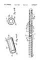
- FIG. 10Ais an enlarged perspective view of a tubular-shaped capacitor of an alternative embodiment of the present invention.
- FIG. 10Bis a cross-sectional view of the tubular-shaped capacitor of FIG. 10A taken along line 10B--10B.
- FIG. 11is a partial sectional view of the microwave antenna of the present invention employing the tubular-shaped capacitor of FIG. 10A.
- FIG. 1is a vertical sectional view of a male pelvic region showing the effect benign prostatic hyperplasia (BPH) has on urinary organs.
- Urethra 10is a duct leading from bladder 12, through prostate 14 and out orifice 16 of penis end 18. Benign tumorous tissue growth within prostate 14 around urethra 10 causes constriction 20 of urethra 10, which interrupts the flow of urine from bladder 12 to orifice 16.
- the tumorous tissue of prostate 14 which encroaches urethra 10 and causes constriction 20can be effectively removed by heating and necrosing the encroaching tumorous tissue.
- periurethral tumorous tissue of prostate 14 anterior and lateral to urethra 10is heated and necrosed to avoid unnecessary and undesirous damage to urethra 10 and to adjacent healthy tissues, such as ejaculatory duct 24 and rectum 26.
- Selective heating of benign tumorous tissue of prostate 14is made possible by microwave antenna-containing catheter 28 of the present invention, which is shown in FIGS. 2A and 2B.
- FIG. 2Ashows a side view of a distal end of catheter 28, while FIG. 2B shows an enlarged sectional view of a proximal end of catheter 28.
- catheter 28generally includes multi-port manifold 30, multi-lumen shaft 32, shaft position retention balloon 34, connection manifold 35, cooling system 36 and microwave generating source 38.
- Manifold 30includes inflation port 40, urine drainage port 42, microwave antenna port 44, cooling fluid in port 46 and cooling fluid out port 48. Ports 40-48 communicate with corresponding lumens within shaft 32. Manifold 30 is preferably made of medical-grade silicone sold by Dow Corning under the trademark Silastic Q-7-4850.
- Shaft 32is connected to manifold 30 at shaft distal end 50.
- Shaft 32is a multi-lumen, Foley-type urethral catheter shaft which is extruded from a flexible, medical-grade silicone sold by Dow Corning under the trademark Silastic Q-7-4850.
- Shaft 32which has an outer diameter of between about 16 French to 22 French, includes outer surface 52, which is generally elliptical in cross-section as shown in FIG. 3.
- Shaft 32is long enough to permit insertion of proximal shaft end 54 through urethra 10 and into bladder 12.
- shaft 32is coated with a hydrophilic solution sold by Hydromer, Inc. under the mark Hydromer, which lubricates outer surface 52 of shaft 32 and facilitates its advancement within urethra 10.
- shaft 32includes temperature sensing lumen 56, microwave antenna lumen 58, urine drainage lumen 60, balloon inflation lumen 62, cooling fluid intake lumens 64A and 64B, and cooling fluid exhaust lumens 66A and 66B.
- Lumens 56-66Bgenerally extend from distal shaft end 50 to proximal shaft end 54.
- Temperature sensing lumen 56is positioned near first side 68 of shaft 32. Temperature sensing lumen 56 communicates with microwave antenna port 44 and permits insertion of thermometry sensor 69 within shaft 32 to monitor temperature when shaft 32 is inserted within urethra 10. Sensor 69 exits through port 44 and is connected through connection manifold 35 to urethral thermometry unit 178B (shown in FIG. 9). In a preferred embodiment, thermometry sensor 69 is a fiber optic luminescence type temperature sensor sold by Luxtron Corporation. Temperature sensing lumen 56 is sealed at proximal end 54 by silicone plug 70.
- Microwave antenna lumen 58is eccentric to the longitudinal axis of shaft 32, antenna lumen 58 being positioned nearer first side 68 of shaft 32 than second side 72 of shaft 32.
- Antenna lumen 58is sealed at proximal end 54 by silicone plug 70A. At its distal end, antenna lumen 58 communicates with microwave antenna port 44.
- Microwave antenna 74is permanently positioned within antenna lumen 58 near balloon 34.
- Antenna 74is positioned within antenna lumen 58 so as to be generally situated adjacent the benign tumorous tissue of prostate 14 when shaft 32 is properly positioned within urethra 10. As shown in FIGS. 2A-2B, antenna 74 is bonded within antenna lumen 58 by adhesive bond 75.
- Antenna 74is carried at the proximal-most end of coaxial cable 76.
- the distal-most end of coaxial cable 76is connected to connection manifold 35 by a conventional quick-coupling fitting 73.
- Coaxial cable 76communicates with microwave generating source 38 by connection cable 76A, which is connected between microwave generating source 38 and connection manifold 35.
- connection cable 76Ais a standard RG 400 coaxial cable.
- Microwave generating source 38produces a maximum of 100 watts of electrical power at about 915 MHz frequency, +/- 13 MHz, which is within the FCC-ISM standards.
- antenna 74When antenna 74 is energized by microwave generating source 38, antenna 74 emits electromagnetic energy which causes heating of tissue within prostate 14.
- Urine drainage lumen 60is positioned adjacent antenna lumen 58, between antenna lumen 58 and second side 72. Urine drainage lumen 60 communicates with urine drainage port 42 and defines a drainage path for urine when proximal end 54 of shaft 32 is inserted within bladder 12. Urine drainage lumen 60 is connected to urine drainage lumen extension 78 at proximal end 54. Urine drainage lumen extension 78 is bonded within proximal end cap 80. End cap 80 is further bonded over outer surface 52 of shaft 32 at proximal shaft end 54, with cavity 82 surrounding lumen extension 78.
- opening 84 to lumen extension 78permits urine to drain from bladder 12 through urine drainage lumen 60 and out urine drainage port 42 when proximal shaft end 54 is inserted within bladder 12. Drainage of urine from bladder 12 is necessary due to frequent bladder spasms which occur during transurethral thermal therapy.
- Balloon inflation lumen 62is positioned near second side 72, generally between urine drainage lumen 60 and second side 72. Balloon inflation lumen 62 communicates with inflation port 40 and is sealed at proximal end 54 by silicone plug 70B. Balloon inflation lumen 62 communicates with interior 86 of balloon 34 by opening 88.
- Balloon 34which is formed from a tubular section of a flexible, medical-grade silicone sold by Dow Corning under the trademark Silastic Q-7-4720, is secured over shaft 32 by bonding balloon waists 90 and 92 over exterior surface 52 of shaft 32 near proximal shaft end 54. Balloon 34 is inflated by an inflation device 188 (shown in FIG. 9), which is connected to inflation port 40 and which supplies positive fluid pressure to interior 86 of balloon 34. Balloon 34 is deflated when inflation device 188 supplies a negative fluid pressure (i.e., a vacuum) to interior 86 of balloon 34. Balloon 34 serves to retain shaft 32 in a fixed position within urethra 10 when balloon 34 is inflated within bladder 12 near bladder neck 22, as shown in FIG. 5.
- cooling fluid intake lumens 64A, 64Bare positioned circumjacent first side 68, between first side 68 and antenna lumen 58. Cooling fluid intake lumens 64A, 64B extend from distal shaft end 50 to proximal shaft end 54 where lumens 64A, 64B are exposed to cavity 82 of end cap 80. Intake lumens 64A, 64B are relatively narrow in cross-section and have a relatively small cross-sectional surface area. Water contained within intake lumens 64A, 64B performs two essential functions. First, water contained within lumens 64A, 64B absorbs some of the microwave energy emitted by antenna 74.
- the water within lumens 64A, 64Babsorbs heat energy generated by the microwave energy from adjacent tissues (i.e., urethra 10) via thermal conduction. This prevents the portion of urethra 10 adjacent first side 68 from being overheated and damaged when antenna 74 is energized.
- Cooling fluid exhaust lumens 66A, 66Bare circumjacent second side 72 with lumens 66A, 66B generally positioned between second side 72 and antenna lumen 58. Like intake lumens 64A, 64B, exhaust lumens 66A, 66B extend from shaft distal end 50 to shaft proximal end 54 where exhaust lumens 66A, 66B are exposed to cavity 82 of end cap 80. Exhaust lumens 66A, 66B are wider in cross-section than intake lumens 64A, 64B, and have a cross-sectional area greater than the cross-sectional area of intake lumens 64A, 64B.
- Water within exhaust lumens 66A, 66Bis therefore capable of absorbing a greater amount of microwave energy when antenna 74 is energized. As a result, for a given power output from microwave generating source 38, the temperature of tissue adjacent second side 72 will remain below about 45° C. Water within exhaust lumens 66A, 66B also absorbs heat energy from adjacent tissue (i.e., urethra 10) when antenna 74 is energized, which prevents the portion of urethra 10 adjacent second side 72 from being overheated and damaged when antenna 74 is energized.
- adjacent tissuei.e., urethra
- Intake lumens 64A, 64B and exhaust lumens 66A, 66Bare supplied with deionized water from cooling system 36.
- Water from cooling system 36is chilled to between about 12°-15° C. and pumped at a rate of between about 100-150 milliliters per minute via water feed line 94A to connection manifold 35.
- the waterflows through connection manifold 35 to water feed line 94B and to water intake port 46, which communicates with water intake lumens 64A, 64B.
- the watercirculates through intake lumens 64A, 64B to cavity 82 of end cap 80.
- the waterreturns to cooling system 36 through exhaust lumens 66A, 66B to fluid exhaust port 48.
- Water feed line 94B and water return line 96Bare each provided with a conventional quick-coupling fitting 65A and 65B, respectively, which permits catheter 28 to be easily disconnected from cooling system 36.
- FIG. 5shows an enlarged view of the male pelvic region of FIG. 1 with catheter 28 properly positioned within urethra 10.
- Orientation stripe 98 along exterior surface 52 on first side 68, as shown in FIG. 4,ensures the proper orientation of shaft 32 within urethra 10.
- shaft 32is positioned within urethra 10 with second side 72 of shaft 32 oriented toward rectum 26.
- Water exhaust lumens 66A, 66Bare oriented posteriorly, toward rectum 26 and water intake lumens 64A, 64B are oriented anteriorly toward fibromuscular tissue 100 of prostate 14.
- the portion of transition zone 101 anterior and lateral to urethra 10is the most frequent location of the tumorous tissue growth which causes BPH.
- water exhaust lumens 66A, 66Bare capable of absorbing more microwave energy than water intake lumens 64A, 64B, the radiation patterns created by microwave energy emitted from antenna 74 are asymmetrical.
- a relatively large volume of tissue enveloping the anterior portion of transition zone 101, adjacent first side 68is heated to a temperature above about 45° C., which effectively necroses the tumorous tissue of prostate 14 which encroaches upon urethra 10.
- the temperature of tissue adjacent second side 72remains below about 45° C., thereby eliminating the harmful effects of the microwave energy to ejaculatory duct 24 and rectum 26.
- FIG. 6is a graph which generally demonstrates a microwave thermal therapy procedure and a temperature distribution which was generated by catheter 28 of the present invention, with shaft 32 inserted into a polyacrylamide gel formulation which simulates biological tissue.
- the formulation and preparation procedures for the polyacrylamide gelare discussed in detail in D. Andreuccetti, M. Bini, A. Ignesti, R. Olmi, N. Rubino, and R. Vanni, Use of Polyacrylamide as a Tissue-Equivalent Material in the Microwave Range, 35 IEEE TRANSACTIONS ON BIOMEDICAL ENGINEERING 275 (NO. 4, April 1988).
- FIG. 6shows temperature measurements taken from eight temperature sensors. Four sensors were aligned at fixed distances adjacent first side 68. Sensor 1A was positioned immediately adjacent shaft 32; sensor 1B was positioned about 0.66 cm from shaft 32; sensor 1C was positioned about 1.33 cm from shaft 32; and sensor 1D was positioned about 2.0 cm from shaft 32.
- Sensor 2Awas positioned immediately adjacent shaft 32; sensor 2B was positioned about 0.66 cm from shaft 32; sensor 2C was positioned about 1.33 cm from shaft 32; and sensor 2D was positioned about 2.0 cm from shaft 32.
- the x-axisrepresents a relative period of time over which the microwave thermal therapy procedure was performed.
- the y-axisrepresents temperature in degrees Celsius, with horizontal line H representing 45° C. (the temperature at or above which cells are necrosed).
- the microwave thermal therapy procedure of the present inventionincludes five operating phases, P1-P5.
- Lines 1A-1D and 2A-2Dcorrespond with sensors 1A-1D and 2A-2D, respectfully.
- first phase P1cooling system 36 is turned on and chilled water is pumped through cooling lumens 64A, 64B and 66A, 66B.
- a drop in temperature immediately adjacent shaft 32is represented by lines 1A, 2A.
- cooling system 36is turned off.
- a relatively small amount of power(about 5 watts) is applied to microwave antenna 74.
- the temperature immediately adjacent shaft 32rises asymmetrically due to the greater absorptivity of water in the larger exhaust lumens 66A, 66B on second side 72, as shown by lines 1A, 2A.
- the poweris applied long enough to merely warm adjacent tissue to about 40° C.
- temperaturesgenerally return to base line temperature.
- the tissue responses to the chilling during P1 and the heating during P2aid in determining the vascularity of the tissue to be treated. This information aids in determining the amount of power necessary to treat tumorous tissue of prostate 14.
- cooling system 36is again turned on thereby pumping chilled water through cooling lumens 64A-66B.
- the temperature immediately adjacent shaft 32correspondingly drops as indicated by lines 1A, 2A. Prechilling of the tissue immediately adjacent shaft 32 aids in protecting the tissues immediately adjacent shaft 32 (i.e., urethra 10) from overheating due to a relatively rapid application of power from antenna 74.
- Microwave generating source 38is again turned on at the beginning of fourth phase P4 at a sustained power output of about 20 watts.
- temperatures adjacent second side 72represented by lines 2A-2D
- temperatures adjacent first side 68represented by lines 1A-1D.
- the temperature differentialsare most profound within a target volume of tissue 0.66 cm from shaft 32. Within this target volume, as shown by lines 1A, 2A and 1B, 2B, the difference in temperature from first side 68 and second side 72 is on the order of about 10° C.
- tissue within 0.66 cm of first side 68can be heated to temperatures at or above about 45° C., while tissue within 0.66 cm of second side 72 can remain at temperatures substantially below 45° C.
- tissue-necrosing temperatures within the target volumeare essentially restricted only to tissue near first side 68, which is the most frequent location of periurethral tumorous prostatic tissue.
- a relatively small volume of tissue adjacent second side 72can be heated above about 45° C. to necrose some of the tumorous prostatic tissue which is posterior and lateral to the urethra.
- microwave generating source 38is operated for at least about 45 minutes.
- the temperature of tissue immediately adjacent shaft 32(which is representative of temperatures of urethra 10), as well as temperatures of tissue beyond 0.66 cm from shaft 32, as shown by lines 1C, 2C and 1D, 2D, are maintainable well below 45° C. This is accomplished by adjusting cooling system parameters and, if necessary, power output from microwave generating source 38.
- cooling system 36continues to operate, circulating water through cooling lumens 64A-66B. A temperature drop immediately adjacent shaft 32 is relatively rapid as shown by lines 1A, 2A within P5.
- cooling system 36continues to operate for a period of time (on the order of 10 to 120 minutes) after the procedure to cool urethra 10 and reduce edema resulting from the application of heat to the periurethral tissues of prostate 14.
- water feed line 94B, water return line 96B and thermometry sensor 69are disconnected from connection manifold 35.
- Water feed line 94B and water return line 96B of catheter 28are then connected to another cooling system similar to cooling system 36 and water is then circulated through cooling lumens 64A-66B in a manner similar to that previously described. In this fashion, recovery from the previously described procedure can be accomplished away from the treatment area thereby enabling microwave generating source 38 and cooling system 36 to be readily available for treatment of another patient.
- FIG. 7shows a partial sectional view of microwave antenna 74 of the present invention.
- Antenna 74is positioned at a proximal-most end of shielded coaxial cable 76.
- Cable 76is a standard RG 178U coaxial cable and includes inner conductor 120, inner insulator 122, outer conductor 124, and outer insulator 126.
- Outer insulator 126, outer conductor 124 and inner insulator 122are stripped away to expose about 3 millimeters of outer conductor 124, about 1 millimeter of inner insulator 122 and about 1 millimeter of inner conductor 120.
- Capacitor 128includes first end 130, which is connected to inner conductor 120 by soldering, and second end 132, which connects to antenna 74.
- Capacitor 128serves to counteract a reactive component of antenna 74, thereby providing a 50 ohm match between coaxial cable 76 and microwave generating source 38, and antenna 74.
- Tubular extension 134which is a hollow section of outer insulator 126 of coaxial cable 76, is positioned over capacitor 128 and the exposed length of inner insulator 122 and secured by bond 136.
- Tubular extension 134includes hole 138, which provides an exit for second end 132 of capacitor 128.
- Wound about outer insulator 126 and tubular extension 134is flat wire 140.
- Flat wire 140is a single piece of flat copper wire with dimensions of about 0.009 inch by about 0.032 inch in cross-section, which provides a relatively large surface area for maximum current flow while minimizing the cross-sectional size of antenna 74.
- FIG. 8is an exploded view of a portion of antenna 74 which shows its helical dipole construction.
- the efficiency of any dipole antennais greatest when the effective electrical length of the antenna is generally one half the wavelength of the radiation emitted in the surrounding medium. Accordingly, a relatively efficient simple dipole antenna, operating at about 915 MHz, would require a physical length of about 8 centimeters which, according to the present invention, would needlessly irradiate and damage healthy tissue. Furthermore, the physical length of a relatively efficient simple dipole antenna operating at about 915 MHz cannot be varied.
- first and second wire sections 142 and 144are each comprised of eight, equally-spaced windings of flat wire 140.
- the combined length of first and second wire sections 142 and 144, and hence the overall length of antenna 74ranges from about 1.5 centimeters to about 4.0 centimeters, and varies according to the length of the area of prostate 14 which requires treatment.
- a standard medical-grade silicone tube(not shown), which has been allowed to soak in a solvent, such as Freon, is positioned over first and second wire sections 142 and 144. As the solvent evaporates, the silicone tube shrinks, thereby securing flat wire 140 to outer insulator 126 and tubular extension 134.
- a solventsuch as Freon
- antenna 74has an effective electrical length generally equal to one half of the wavelength of the radiation emitted in the surrounding medium, independent of its physical length.
- the surrounding mediumincludes the catheter shaft and the surrounding tissue. This is accomplished by varying the number and pitch of the windings of first and second wire sections 142 and 144.
- a family of catheters, which contain relatively efficient helical dipole antennas of different physical lengths,permits selection of the antenna best suited for the particular treatment area.
- antenna 74 of the present inventionis capable of producing a constant heating pattern in tissue, concentrated about antenna 74, independent of the depth of insertion into the tissue.
- Tap point 148is a point at which the resistive component of the combined impedance of first wire section 142 and second wire section 144 matches the characteristic impedance of coaxial cable 76.
- the impedance Zvaries from a low value at solder point 146 to a high value at a point farthest from solder point 146. There exists a tap position where R is equal to 50 ohms, but an imaginary component, X, is inductive.
- This inductive componentcan be canceled by inserting a series capacitance, such as capacitor 128, which has a value of -jX ohms. This results in an impedance match of 50 ohms real.
- the resulting method of feeding antenna 74is commonly called gamma matching.
- tap point 148is about 3.5 turns from solder point 146 on second wire section 144.
- the value of capacitor 128is about 2.7 pF.
- appropriate values of capacitor 128can be easily determined.
- the helical dipole construction of antenna 74achieves a relatively small size, which permits intraurethral application.
- the helical dipole constructionis also responsible for three features which enable antenna 74 to achieve greater efficiency than prior known interstitial microwave antennas: good impedance matching, good current carrying capability and an effective electrical length which is generally one half of the wavelength of the radiation emitted in the surrounding medium, independent of the physical length of antenna 74.
- the good impedance match between antenna 74 and inner conductor 120minimizes reflective losses of antenna 74, with measured reflective losses of less than 1% in a preferred embodiment.
- the use of flat ribbon wire 140 for first wire section 142 and second wire section 144minimizes resistive losses of antenna 74 by providing a greater surface area upon which RF current can be carried.
- the helical dipole design of antenna 74has an effective electrical length which is generally one half of the wavelength of the radiation emitted in the surrounding medium, independent of the physical length of antenna 74. This permits the physical length of antenna 74 to be varied to accommodate varying sizes of individual prostates while maintaining the same efficient, effective electrical length of antenna 74.
- an efficient microwave antennais critical to the ability to focus thermal energy a distance from the antenna within a target volume.
- An inefficient antennaproduces a lesser intensity of microwave radiation within the target volume than desired. It also produces undesired heat close to the urethra, which will damage the urethra if not carried away by an increased coolant flow.
- This added burden on the cooling systemreduces its capacity to protect the urethra, thereby limiting the microwave power that can be radiated without elevating urethra temperatures above safety limits. With microwave power limited by cooling system capacity, the heat delivered to the desired target area of the prostate will not be sufficient for effective therapy.
- the efficient helical dipole design of antenna 74 of the present inventionensures that almost all heat delivered during the treatment is delivered in the form of microwave energy, rather than conductive heat energy.
- FIG. 9is a block diagram of transurethral microwave thermal therapy system 170, with which urethral catheter 28 is used.
- System 170includes cooling system 36 microwave generating source 38, user interface 172, real time controller (RTC) 174, directional coupler 176, thermometry sensors 182 and 184, coolant pressure sensor 186, balloon inflation device 188, and urine collection container 190.
- RTCreal time controller
- control of microwave generating source 38 and cooling system 36is effected by real time controller 174, which is in turn controlled by user interface 172.
- User interface 172is an IBM compatible machine containing two hard drives for data storage: one for backup, and one for normal operation of system 170.
- User interface 172communicates with RTC 174, which is responsible for all closed loop feedback to run system 170.
- RTC 174has direct closed loop control of microwave power from microwave generating source 38, and coolant flow and coolant temperature of cooling system 36. Closed loop feedback tracks out variations in gain, drift and cable losses inherent in microwave generating source 38, and variability in pump output and refrigeration system efficiency of cooling system 36.
- RTC 174In addition to monitoring microwave generating source 38 and cooling system 36, RTC 174 also monitors and controls several channels of thermometry via inputs from thermometry unit 178.
- Cooling system thermometry 178Ameasures the coolant and chiller temperatures based upon signals from coolant temperature sensors 182 and 184 and a chiller temperature sensor (not shown) of cooling system 36.
- Urethral thermometry 178Bmeasures urethral temperature based upon signals from temperature sensor 69 within catheter 28.
- Rectal thermometry 178Cmeasures rectal temperature based upon signals received from a sensor (not shown) within rectal probe 180.
- RTC 174transmits all closed-loop feedback to user interface 172, which processes the input and transmits corrections and instructions back to RTC 174.
- RTC 174interprets the instructions given to it by process control language received from user interface 172 and executes the instructions in real time. All corrections from user interface 172 are made to maintain a given thermal profile throughout the transurethral thermal therapy.
- system 170includes a hardware fail-safe circuit which shuts down system 170 should any parameter fall outside a given range of values.
- FIGS. 10A, 10B and 11show a tubular-shaped capacitor 200 used in another embodiment of antenna 214.
- Antenna 214is constructed in a manner similar to antenna 76, which is shown in FIGS. 7 and 8.
- capacitor 200comprises dielectric tube 202 with outer conductive layer 204 and inner conductive layer 206. Outer conductive layer 204 and inner conductive layer 206 form concentric plates of capacitor 200.
- Metal ring 208which includes tab 210, fits over outer conductive layer 204. Ring 208 is positionable along capacitor 200 so as to locate tab 210 at the desired tap point, similar to tap point 148 of FIG. 7, when capacitor 200 is connected to antenna 214 (shown in FIG. 11). Thereafter, ring 208 is soldered to outer conductive layer 204 of capacitor 200.
- capacitor 200is manufactured by Coors Ceramics Co. of Golden, Colo., with dielectric tube 202 being formed from alumina, and with the inner conductive layer 206 and outer conductive layer 204 being formed by application of a layer of a metal-laced adhesive binder. Ring 208 and tab 210 are preferably formed from any solderable metal, such as brass or copper.
- Capacitor 200has an outer diameter of about 0.050 inches, which permits capacitor 200 to fit within a relatively flexible tubular extension 216 (shown in FIG. 11).
- capacitor 200has an inner diameter of about 0.025 inches, which permits insertion of inner conductor 218 of coaxial cable 220 (shown in FIG. 11) into capacitor 200.
- capacitor 200has a capacitance of about 2.7 pF.
- Capacitor 200also has a length of about 0.110 inches. Other dimensions of capacitor 200 will be apparent to those of ordinary electrical skill.
- FIG. 11is a side view of antenna 214 with a portion cut away to show a connection of capacitor 200 to antenna 214 and coaxial cable 220.
- Antenna 214is connected to coaxial cable 220 in a manner similar to that previously discussed with respect to antenna 74 and coaxial cable 76 (FIG. 7).
- metal band 222(which is similar to ring 208) is positioned over inner insulator 223 and outer conductor 224 and connected by soldering to outer conductor 224 of coaxial cable 220.
- Metal band 222includes tab 226, which is connected by soldering to flat wire 228 so as to produce first antenna section 214A and second antenna section 214B.
- first and second wire sections 142 and 144 of antenna 74shown in FIG.
- first antenna section 214A and second antenna section 214Bare approximately equal in length.
- Metal band 222is sized to be located within tubular extension 216 when tubular extension 216 is positioned over inner insulator 223 and outer conductor 224.
- a groove in tubular extension 216(not shown) enables the connection of tab 226 of metal band 222 to flat wire 228.
- capacitor 200Prior to the positioning of tubular extension 216, capacitor 200 is slipped over inner conductor 218. Inner conductive layer 206 of capacitor 200 is thereafter connected to inner conductor 218 by soldering. Capacitor 200 is preferably spaced apart from outer conductor 224 by at least about 0.050 inches to avoid a short between outer conductor 224 and outer conductive layer 204 of capacitor 200. With capacitor 200 connected to inner conductor 218, the relatively flexible tubular extension 216 is slipped over capacitor 200, ring 208, inner insulator 223 and outer conductor 224 until tab 210 of ring 208 engages hole 230 of tubular extension 216. Hole 230 is located so as to expose tab 210 for soldering to second antenna section 214B at tap point 232. Tap point 232, like tap point 148 of FIG. 7, is the point at which the resistive component of the combined impedance of first antenna section 214A and second antenna section 214B matches the characteristic impedance of coaxial cable 220.
- capacitor 200provides for a highly reliable connection to inner conductor 218 and tap point 232.
- capacitor 200permits adjustment of tap point 232 by virtue of the adjustability of ring 208.
- capacitor 200is able to be adapted for use with various antenna dimensions.
Landscapes
- Health & Medical Sciences (AREA)
- Life Sciences & Earth Sciences (AREA)
- Biomedical Technology (AREA)
- Engineering & Computer Science (AREA)
- Veterinary Medicine (AREA)
- Animal Behavior & Ethology (AREA)
- Public Health (AREA)
- Nuclear Medicine, Radiotherapy & Molecular Imaging (AREA)
- General Health & Medical Sciences (AREA)
- Surgery (AREA)
- Heart & Thoracic Surgery (AREA)
- Molecular Biology (AREA)
- Medical Informatics (AREA)
- Electromagnetism (AREA)
- Otolaryngology (AREA)
- Physics & Mathematics (AREA)
- Pathology (AREA)
- Radiology & Medical Imaging (AREA)
- Thermotherapy And Cooling Therapy Devices (AREA)
- Radiation-Therapy Devices (AREA)
- Support Of Aerials (AREA)
- Details Of Aerials (AREA)
Abstract
Description
Claims (15)
Priority Applications (6)
| Application Number | Priority Date | Filing Date | Title |
|---|---|---|---|
| US08/123,321US5370677A (en) | 1992-03-06 | 1993-09-17 | Gamma matched, helical dipole microwave antenna with tubular-shaped capacitor |
| CA002169338ACA2169338A1 (en) | 1993-09-17 | 1994-08-12 | Gamma matched, helical dipole microwave antenna with tubular-shaped capacitator |
| JP7509178AJPH09502630A (en) | 1993-09-17 | 1994-08-12 | Gamma-matched spiral dipole microwave antenna with tubular capacitors |
| EP94925856AEP0723468A4 (en) | 1993-09-17 | 1994-08-12 | Gamma matched, helical dipole microwave antenna with tubular-shaped capacitor |
| PCT/US1994/009145WO1995007730A1 (en) | 1993-09-17 | 1994-08-12 | Gamma matched, helical dipole microwave antenna with tubular-shaped capacitor |
| AU79200/94AAU678624B2 (en) | 1993-09-17 | 1994-08-12 | Gamma matched, helical dipole microwave antenna with tubular-shaped capacitor |
Applications Claiming Priority (2)
| Application Number | Priority Date | Filing Date | Title |
|---|---|---|---|
| US07/847,915US5300099A (en) | 1992-03-06 | 1992-03-06 | Gamma matched, helical dipole microwave antenna |
| US08/123,321US5370677A (en) | 1992-03-06 | 1993-09-17 | Gamma matched, helical dipole microwave antenna with tubular-shaped capacitor |
Related Parent Applications (1)
| Application Number | Title | Priority Date | Filing Date |
|---|---|---|---|
| US07/847,915Continuation-In-PartUS5300099A (en) | 1992-03-06 | 1992-03-06 | Gamma matched, helical dipole microwave antenna |
Publications (1)
| Publication Number | Publication Date |
|---|---|
| US5370677Atrue US5370677A (en) | 1994-12-06 |
Family
ID=22407967
Family Applications (1)
| Application Number | Title | Priority Date | Filing Date |
|---|---|---|---|
| US08/123,321Expired - LifetimeUS5370677A (en) | 1992-03-06 | 1993-09-17 | Gamma matched, helical dipole microwave antenna with tubular-shaped capacitor |
Country Status (6)
| Country | Link |
|---|---|
| US (1) | US5370677A (en) |
| EP (1) | EP0723468A4 (en) |
| JP (1) | JPH09502630A (en) |
| AU (1) | AU678624B2 (en) |
| CA (1) | CA2169338A1 (en) |
| WO (1) | WO1995007730A1 (en) |
Cited By (91)
| Publication number | Priority date | Publication date | Assignee | Title |
|---|---|---|---|---|
| US5572172A (en)* | 1995-08-09 | 1996-11-05 | Qualcomm Incorporated | 180° power divider for a helix antenna |
| WO1996036397A1 (en)* | 1995-05-15 | 1996-11-21 | Arrow International Investment Corp. | Microwave antenna catheter |
| WO1997035639A1 (en)* | 1996-03-26 | 1997-10-02 | Urologix, Inc. | Voltage controlled variable tuning antenna |
| US5693082A (en)* | 1993-05-14 | 1997-12-02 | Fidus Medical Technology Corporation | Tunable microwave ablation catheter system and method |
| US5741249A (en)* | 1996-10-16 | 1998-04-21 | Fidus Medical Technology Corporation | Anchoring tip assembly for microwave ablation catheter |
| US5793338A (en)* | 1995-08-09 | 1998-08-11 | Qualcomm Incorporated | Quadrifilar helix antenna and feed network |
| US5800494A (en)* | 1996-08-20 | 1998-09-01 | Fidus Medical Technology Corporation | Microwave ablation catheters having antennas with distal fire capabilities |
| US5802479A (en)* | 1994-09-23 | 1998-09-01 | Advanced Safety Concepts, Inc. | Motor vehicle occupant sensing systems |
| US5810803A (en)* | 1996-10-16 | 1998-09-22 | Fidus Medical Technology Corporation | Conformal positioning assembly for microwave ablation catheter |
| US5828348A (en)* | 1995-09-22 | 1998-10-27 | Qualcomm Incorporated | Dual-band octafilar helix antenna |
| US5827268A (en)* | 1996-10-30 | 1998-10-27 | Hearten Medical, Inc. | Device for the treatment of patent ductus arteriosus and method of using the device |
| WO1998049933A1 (en) | 1997-05-06 | 1998-11-12 | Urologix, Inc. | Device and method for preventing restenosis |
| US5843144A (en)* | 1995-06-26 | 1998-12-01 | Urologix, Inc. | Method for treating benign prostatic hyperplasia with thermal therapy |
| US5989284A (en)* | 1997-02-18 | 1999-11-23 | Hearten Medical, Inc. | Method and device for soft tissue modification |
| US6033398A (en)* | 1996-03-05 | 2000-03-07 | Vnus Medical Technologies, Inc. | Method and apparatus for treating venous insufficiency using directionally applied energy |
| US6033397A (en)* | 1996-03-05 | 2000-03-07 | Vnus Medical Technologies, Inc. | Method and apparatus for treating esophageal varices |
| US6035238A (en)* | 1997-08-13 | 2000-03-07 | Surx, Inc. | Noninvasive devices, methods, and systems for shrinking of tissues |
| US6036687A (en)* | 1996-03-05 | 2000-03-14 | Vnus Medical Technologies, Inc. | Method and apparatus for treating venous insufficiency |
| US6047216A (en)* | 1996-04-17 | 2000-04-04 | The United States Of America Represented By The Administrator Of The National Aeronautics And Space Administration | Endothelium preserving microwave treatment for atherosclerosis |
| US6071303A (en)* | 1996-12-08 | 2000-06-06 | Hearten Medical, Inc. | Device for the treatment of infarcted tissue and method of treating infarcted tissue |
| US6081749A (en)* | 1997-08-13 | 2000-06-27 | Surx, Inc. | Noninvasive devices, methods, and systems for shrinking of tissues |
| US6091995A (en)* | 1996-11-08 | 2000-07-18 | Surx, Inc. | Devices, methods, and systems for shrinking tissues |
| US6123703A (en)* | 1998-09-19 | 2000-09-26 | Tu; Lily Chen | Ablation catheter and methods for treating tissues |
| US6135997A (en)* | 1996-03-05 | 2000-10-24 | Vnus Medical Technologies, Inc. | Method for treating hemorrhoids |
| US6233490B1 (en)* | 1999-02-09 | 2001-05-15 | Kai Technologies, Inc. | Microwave antennas for medical hyperthermia, thermotherapy and diagnosis |
| US6292700B1 (en) | 1999-09-10 | 2001-09-18 | Surx, Inc. | Endopelvic fascia treatment for incontinence |
| US6440127B2 (en) | 1998-02-11 | 2002-08-27 | Cosman Company, Inc. | Method for performing intraurethral radio-frequency urethral enlargement |
| US6447505B2 (en) | 1998-02-11 | 2002-09-10 | Cosman Company, Inc. | Balloon catheter method for intra-urethral radio-frequency urethral enlargement |
| US6480746B1 (en) | 1997-08-13 | 2002-11-12 | Surx, Inc. | Noninvasive devices, methods, and systems for shrinking of tissues |
| US6517534B1 (en) | 1998-02-11 | 2003-02-11 | Cosman Company, Inc. | Peri-urethral ablation |
| US6546934B1 (en) | 1996-11-08 | 2003-04-15 | Surx, Inc. | Noninvasive devices and methods for shrinking of tissues |
| US20030191511A1 (en)* | 1999-04-16 | 2003-10-09 | Tony R. Brown | Device for shaping infarcted heart tissue and method of using the device |
| US6638273B1 (en) | 1996-03-05 | 2003-10-28 | Vnus Medical Technologies, Inc. | Expandable catheter having improved electrode design, and method for applying energy |
| US6743226B2 (en) | 2001-02-09 | 2004-06-01 | Cosman Company, Inc. | Adjustable trans-urethral radio-frequency ablation |
| US20040254621A1 (en)* | 1997-09-11 | 2004-12-16 | Jones Christopher S. | Expandable catheter having two sets of electrodes, and method of use |
| US20040267336A1 (en)* | 1996-11-08 | 2004-12-30 | Solarant Medical, Inc. | Energy induced bulking and buttressing of tissues for incontinence |
| US6976986B2 (en) | 2000-04-12 | 2005-12-20 | Afx, Inc. | Electrode arrangement for use in a medical instrument |
| US7033352B1 (en) | 2000-01-18 | 2006-04-25 | Afx, Inc. | Flexible ablation instrument |
| US7052491B2 (en) | 1998-10-23 | 2006-05-30 | Afx, Inc. | Vacuum-assisted securing apparatus for a microwave ablation instrument |
| US7099717B2 (en) | 2002-01-03 | 2006-08-29 | Afx Inc. | Catheter having improved steering |
| US7118590B1 (en) | 1999-02-25 | 2006-10-10 | Microsulis Limited | Radiation applicator |
| US7192427B2 (en) | 2002-02-19 | 2007-03-20 | Afx, Inc. | Apparatus and method for assessing transmurality of a tissue ablation |
| US20070093880A1 (en)* | 2005-10-06 | 2007-04-26 | Boston Scientific Scimed, Inc. | Adjustable profile probe |
| US7226446B1 (en) | 1999-05-04 | 2007-06-05 | Dinesh Mody | Surgical microwave ablation assembly |
| US7303560B2 (en) | 2000-12-29 | 2007-12-04 | Afx, Inc. | Method of positioning a medical instrument |
| US20080015570A1 (en)* | 1998-12-14 | 2008-01-17 | Ormsby Theodore C | Hollow conductive coaxial cable for radio frequency based tissue ablation system |
| US7346399B2 (en) | 1999-05-28 | 2008-03-18 | Afx, Inc. | Monopole tip for ablation catheter |
| US20080071265A1 (en)* | 2006-09-14 | 2008-03-20 | Larry Azure | Device and method for destruction of cancer cells |
| US20090076496A1 (en)* | 2007-09-14 | 2009-03-19 | Lazure Technologies Llc. | Prostate cancer ablation |
| US20090076499A1 (en)* | 2007-09-14 | 2009-03-19 | Lazure Technologies, Llc. | Multi-layer electrode ablation probe and related methods |
| US20090082762A1 (en)* | 2007-09-20 | 2009-03-26 | Ormsby Theodore C | Radio frequency energy transmission device for the ablation of biological tissues |
| US7536225B2 (en) | 2005-01-21 | 2009-05-19 | Ams Research Corporation | Endo-pelvic fascia penetrating heating systems and methods for incontinence treatment |
| US20090270791A1 (en)* | 2008-04-28 | 2009-10-29 | Urotech, Inc. | Benign prostatic hyperplasia surgical system featuring mechanical coring probe with live aspiration |
| US20090287204A1 (en)* | 2005-01-14 | 2009-11-19 | Co-Repair, Inc. | System And Method For The Treatment Of Heart Tissue |
| US20100004650A1 (en)* | 2008-07-01 | 2010-01-07 | Medwaves, Inc. | Angioplasty and tissue ablation apparatus and method |
| US20100114275A1 (en)* | 2008-10-30 | 2010-05-06 | Pacesetter, Inc. | Implantable medical lead including winding for improved mri safety |
| US20110009858A1 (en)* | 2001-11-29 | 2011-01-13 | Medwaves, Inc. | Radio frequency-based catheter system with improved deflection and steering mechanisms |
| US20110009804A1 (en)* | 2009-07-08 | 2011-01-13 | Tyco Healthcare Group Lp | Method and System for Delivering a Medicant |
| US20110130750A1 (en)* | 2009-11-30 | 2011-06-02 | Medwaves, Inc. | Radio frequency ablation system with tracking sensor |
| US20120004651A1 (en)* | 2010-06-30 | 2012-01-05 | Vivant Medical, Inc. | Microwave Antenna Having a Reactively-Loaded Loop Configuration |
| US8285393B2 (en) | 1999-04-16 | 2012-10-09 | Laufer Michael D | Device for shaping infarcted heart tissue and method of using the device |
| US8291915B2 (en) | 1997-03-04 | 2012-10-23 | Tyco Healthcare Group Lp | Method and apparatus for treating venous insufficiency using directionally applied energy |
| US8435235B2 (en) | 2007-04-27 | 2013-05-07 | Covidien Lp | Systems and methods for treating hollow anatomical structures |
| US20130178824A1 (en)* | 2011-07-12 | 2013-07-11 | Verve Medical, Inc. | Renal nerve denervation via the renal pelvis |
| US8593782B1 (en)* | 2010-07-16 | 2013-11-26 | Ut-Battelle, Llc | Clad fiber capacitor and method of making same |
| US8728139B2 (en) | 2009-04-16 | 2014-05-20 | Lazure Technologies, Llc | System and method for energy delivery to a tissue using an electrode array |
| US8832927B2 (en) | 2009-03-10 | 2014-09-16 | Covidien Lp | Method of manufacturing surgical antennas |
| US8968284B2 (en) | 2000-10-02 | 2015-03-03 | Verathon Inc. | Apparatus and methods for treating female urinary incontinence |
| US8992413B2 (en) | 2011-05-31 | 2015-03-31 | Covidien Lp | Modified wet tip antenna design |
| US9023031B2 (en) | 1997-08-13 | 2015-05-05 | Verathon Inc. | Noninvasive devices, methods, and systems for modifying tissues |
| US9198708B2 (en) | 2010-03-25 | 2015-12-01 | Nxthera, Inc. | Systems and methods for prostate treatment |
| US9345507B2 (en) | 2008-11-06 | 2016-05-24 | Nxthera, Inc. | Systems and methods for treatment of BPH |
| US9526911B1 (en) | 2010-04-27 | 2016-12-27 | Lazure Scientific, Inc. | Immune mediated cancer cell destruction, systems and methods |
| US9770297B2 (en) | 2008-06-04 | 2017-09-26 | Covidien Lp | Energy devices and methods for treating hollow anatomical structures |
| US9833277B2 (en) | 2009-04-27 | 2017-12-05 | Nxthera, Inc. | Systems and methods for prostate treatment |
| US9895185B2 (en) | 2011-09-13 | 2018-02-20 | Nxthera, Inc. | Systems and methods for prostate treatment |
| US9968395B2 (en) | 2013-12-10 | 2018-05-15 | Nxthera, Inc. | Systems and methods for treating the prostate |
| CN108039779A (en)* | 2017-12-25 | 2018-05-15 | 天津工业大学 | A kind of wireless power transmission coil with impedance matching function |
| US10194970B2 (en) | 2013-12-10 | 2019-02-05 | Nxthera, Inc. | Vapor ablation systems and methods |
| US10335222B2 (en) | 2012-04-03 | 2019-07-02 | Nxthera, Inc. | Induction coil vapor generator |
| US10342593B2 (en) | 2015-01-29 | 2019-07-09 | Nxthera, Inc. | Vapor ablation systems and methods |
| WO2019150258A3 (en)* | 2018-02-02 | 2019-10-31 | Biocompatibles Uk Limited | Tissue ablation device with broadband antenna |
| US10610281B2 (en) | 2008-11-06 | 2020-04-07 | Boston Scientific Scimed, Inc. | Systems and methods for treatment of prostatic tissue |
| US10702327B2 (en) | 2015-05-13 | 2020-07-07 | Boston Scientific Scimed, Inc. | Systems and methods for treating the bladder with condensable vapor |
| CN111585014A (en)* | 2020-05-07 | 2020-08-25 | 华南理工大学 | A Novel Millimeter-Wave Low Profile Planar Differential Double Helix Antenna |
| US10751107B2 (en) | 2017-01-06 | 2020-08-25 | Boston Scientific Scimed, Inc. | Transperineal vapor ablation systems and methods |
| US10772670B2 (en) | 2013-03-14 | 2020-09-15 | Boston Scientific Scimed, Inc. | Systems and methods for treating prostate cancer |
| US11246640B2 (en) | 2016-12-21 | 2022-02-15 | Boston Scientific Scimed, Inc. | Vapor ablation systems and methods |
| US12161379B2 (en) | 2011-07-12 | 2024-12-10 | Verve Medical, Inc. | Treatment of kidney disease using renal nerve denervation via the renal pelvis |
| US12279800B2 (en) | 2011-07-12 | 2025-04-22 | Verve Medical, Inc. | Methods and devices for treating polycystic kidney disease and its symptoms |
| US12440258B2 (en) | 2023-11-20 | 2025-10-14 | Boston Scientific Scimed, Inc. | Systems and methods for treating prostate cancer |
Families Citing this family (1)
| Publication number | Priority date | Publication date | Assignee | Title |
|---|---|---|---|---|
| EP4368135A1 (en)* | 2022-11-10 | 2024-05-15 | Endowave Ltd. | A microwave ablation probe |
Citations (18)
| Publication number | Priority date | Publication date | Assignee | Title |
|---|---|---|---|---|
| US4154246A (en)* | 1977-07-25 | 1979-05-15 | Leveen Harry H | Field intensification in radio frequency thermotherapy |
| US4583556A (en)* | 1982-12-13 | 1986-04-22 | M/A-Com, Inc. | Microwave applicator/receiver apparatus |
| US4601296A (en)* | 1983-10-07 | 1986-07-22 | Yeda Research And Development Co., Ltd. | Hyperthermia apparatus |
| US4612940A (en)* | 1984-05-09 | 1986-09-23 | Scd Incorporated | Microwave dipole probe for in vivo localized hyperthermia |
| US4776086A (en)* | 1986-02-27 | 1988-10-11 | Kasevich Associates, Inc. | Method and apparatus for hyperthermia treatment |
| US4823812A (en)* | 1986-05-12 | 1989-04-25 | Biodan Medical Systems Ltd. | Applicator for insertion into a body opening for medical purposes |
| US4825880A (en)* | 1987-06-19 | 1989-05-02 | The Regents Of The University Of California | Implantable helical coil microwave antenna |
| US4841988A (en)* | 1987-10-15 | 1989-06-27 | Marquette Electronics, Inc. | Microwave hyperthermia probe |
| US4865047A (en)* | 1988-06-30 | 1989-09-12 | City Of Hope | Hyperthermia applicator |
| US4932420A (en)* | 1988-10-07 | 1990-06-12 | Clini-Therm Corporation | Non-invasive quarter wavelength microwave applicator for hyperthermia treatment |
| US4945318A (en)* | 1988-03-01 | 1990-07-31 | Labthermics Technologies, Inc. | Low frequency isolator for radio frequency hyperthermia probe |
| US4955377A (en)* | 1988-10-28 | 1990-09-11 | Lennox Charles D | Device and method for heating tissue in a patient's body |
| US4967765A (en)* | 1988-07-28 | 1990-11-06 | Bsd Medical Corporation | Urethral inserted applicator for prostate hyperthermia |
| US5026959A (en)* | 1988-11-16 | 1991-06-25 | Tokyo Keiki Co. Ltd. | Microwave radiator for warming therapy |
| US5057106A (en)* | 1986-02-27 | 1991-10-15 | Kasevich Associates, Inc. | Microwave balloon angioplasty |
| US5097845A (en)* | 1987-10-15 | 1992-03-24 | Labthermics Technologies | Microwave hyperthermia probe |
| US5151100A (en)* | 1988-10-28 | 1992-09-29 | Boston Scientific Corporation | Heating catheters |
| US5246438A (en)* | 1988-11-25 | 1993-09-21 | Sensor Electronics, Inc. | Method of radiofrequency ablation |
Family Cites Families (2)
| Publication number | Priority date | Publication date | Assignee | Title |
|---|---|---|---|---|
| DE8705625U1 (en)* | 1987-04-16 | 1987-09-10 | Sillner, Georg, 93197 Zeitlarn | Tube capacitor |
| US5413588A (en)* | 1992-03-06 | 1995-05-09 | Urologix, Inc. | Device and method for asymmetrical thermal therapy with helical dipole microwave antenna |
- 1993
- 1993-09-17USUS08/123,321patent/US5370677A/ennot_activeExpired - Lifetime
- 1994
- 1994-08-12WOPCT/US1994/009145patent/WO1995007730A1/ennot_activeApplication Discontinuation
- 1994-08-12CACA002169338Apatent/CA2169338A1/ennot_activeAbandoned
- 1994-08-12JPJP7509178Apatent/JPH09502630A/enactivePending
- 1994-08-12EPEP94925856Apatent/EP0723468A4/ennot_activeWithdrawn
- 1994-08-12AUAU79200/94Apatent/AU678624B2/ennot_activeCeased
Patent Citations (19)
| Publication number | Priority date | Publication date | Assignee | Title |
|---|---|---|---|---|
| US4154246A (en)* | 1977-07-25 | 1979-05-15 | Leveen Harry H | Field intensification in radio frequency thermotherapy |
| US4583556A (en)* | 1982-12-13 | 1986-04-22 | M/A-Com, Inc. | Microwave applicator/receiver apparatus |
| US4601296A (en)* | 1983-10-07 | 1986-07-22 | Yeda Research And Development Co., Ltd. | Hyperthermia apparatus |
| US4612940A (en)* | 1984-05-09 | 1986-09-23 | Scd Incorporated | Microwave dipole probe for in vivo localized hyperthermia |
| US5057106A (en)* | 1986-02-27 | 1991-10-15 | Kasevich Associates, Inc. | Microwave balloon angioplasty |
| US4776086A (en)* | 1986-02-27 | 1988-10-11 | Kasevich Associates, Inc. | Method and apparatus for hyperthermia treatment |
| US4823812A (en)* | 1986-05-12 | 1989-04-25 | Biodan Medical Systems Ltd. | Applicator for insertion into a body opening for medical purposes |
| US4825880A (en)* | 1987-06-19 | 1989-05-02 | The Regents Of The University Of California | Implantable helical coil microwave antenna |
| US4841988A (en)* | 1987-10-15 | 1989-06-27 | Marquette Electronics, Inc. | Microwave hyperthermia probe |
| US5097845A (en)* | 1987-10-15 | 1992-03-24 | Labthermics Technologies | Microwave hyperthermia probe |
| US4841988B1 (en)* | 1987-10-15 | 1990-08-14 | Marquette Electronics Inc | |
| US4945318A (en)* | 1988-03-01 | 1990-07-31 | Labthermics Technologies, Inc. | Low frequency isolator for radio frequency hyperthermia probe |
| US4865047A (en)* | 1988-06-30 | 1989-09-12 | City Of Hope | Hyperthermia applicator |
| US4967765A (en)* | 1988-07-28 | 1990-11-06 | Bsd Medical Corporation | Urethral inserted applicator for prostate hyperthermia |
| US4932420A (en)* | 1988-10-07 | 1990-06-12 | Clini-Therm Corporation | Non-invasive quarter wavelength microwave applicator for hyperthermia treatment |
| US4955377A (en)* | 1988-10-28 | 1990-09-11 | Lennox Charles D | Device and method for heating tissue in a patient's body |
| US5151100A (en)* | 1988-10-28 | 1992-09-29 | Boston Scientific Corporation | Heating catheters |
| US5026959A (en)* | 1988-11-16 | 1991-06-25 | Tokyo Keiki Co. Ltd. | Microwave radiator for warming therapy |
| US5246438A (en)* | 1988-11-25 | 1993-09-21 | Sensor Electronics, Inc. | Method of radiofrequency ablation |
Non-Patent Citations (4)
| Title |
|---|
| Cheng, David K., Field and Wave Electromagnetics, pp. 112 113.* |
| Cheng, David K., Field and Wave Electromagnetics, pp. 112-113. |
| Hayt, William H., Jr., Engineering Electromagnetics, Fourth Edition, pp. 161 163.* |
| Hayt, William H., Jr., Engineering Electromagnetics, Fourth Edition, pp. 161-163. |
Cited By (169)
| Publication number | Priority date | Publication date | Assignee | Title |
|---|---|---|---|---|
| US5693082A (en)* | 1993-05-14 | 1997-12-02 | Fidus Medical Technology Corporation | Tunable microwave ablation catheter system and method |
| US6014602A (en)* | 1994-09-23 | 2000-01-11 | Advanced Safety Concepts, Inc. | Motor vehicle occupant sensing systems |
| US5802479A (en)* | 1994-09-23 | 1998-09-01 | Advanced Safety Concepts, Inc. | Motor vehicle occupant sensing systems |
| WO1996036397A1 (en)* | 1995-05-15 | 1996-11-21 | Arrow International Investment Corp. | Microwave antenna catheter |
| US5683382A (en)* | 1995-05-15 | 1997-11-04 | Arrow International Investment Corp. | Microwave antenna catheter |
| US5843144A (en)* | 1995-06-26 | 1998-12-01 | Urologix, Inc. | Method for treating benign prostatic hyperplasia with thermal therapy |
| US5572172A (en)* | 1995-08-09 | 1996-11-05 | Qualcomm Incorporated | 180° power divider for a helix antenna |
| US5793338A (en)* | 1995-08-09 | 1998-08-11 | Qualcomm Incorporated | Quadrifilar helix antenna and feed network |
| US5828348A (en)* | 1995-09-22 | 1998-10-27 | Qualcomm Incorporated | Dual-band octafilar helix antenna |
| US6638273B1 (en) | 1996-03-05 | 2003-10-28 | Vnus Medical Technologies, Inc. | Expandable catheter having improved electrode design, and method for applying energy |
| US6033398A (en)* | 1996-03-05 | 2000-03-07 | Vnus Medical Technologies, Inc. | Method and apparatus for treating venous insufficiency using directionally applied energy |
| US6981972B1 (en) | 1996-03-05 | 2006-01-03 | Vnus Medical Technologies, Inc. | Apparatus for treating venous insufficiency using directionally applied energy |
| US6135997A (en)* | 1996-03-05 | 2000-10-24 | Vnus Medical Technologies, Inc. | Method for treating hemorrhoids |
| US6071277A (en)* | 1996-03-05 | 2000-06-06 | Vnus Medical Technologies, Inc. | Method and apparatus for reducing the size of a hollow anatomical structure |
| US6036687A (en)* | 1996-03-05 | 2000-03-14 | Vnus Medical Technologies, Inc. | Method and apparatus for treating venous insufficiency |
| US6613045B1 (en) | 1996-03-05 | 2003-09-02 | Vnus Medical Technologies, Inc. | Method and apparatus for treating venous insufficiency |
| US7641633B2 (en) | 1996-03-05 | 2010-01-05 | Tyco Healthcare Group, Lp | Apparatus for treating venous insufficiency |
| US7976536B2 (en) | 1996-03-05 | 2011-07-12 | Tyco Healthcare Group Lp | Method and apparatus for treating venous insufficiency |
| US6033397A (en)* | 1996-03-05 | 2000-03-07 | Vnus Medical Technologies, Inc. | Method and apparatus for treating esophageal varices |
| US5938692A (en)* | 1996-03-26 | 1999-08-17 | Urologix, Inc. | Voltage controlled variable tuning antenna |
| US6032078A (en)* | 1996-03-26 | 2000-02-29 | Urologix, Inc. | Voltage controlled variable tuning antenna |
| WO1997035639A1 (en)* | 1996-03-26 | 1997-10-02 | Urologix, Inc. | Voltage controlled variable tuning antenna |
| US6047216A (en)* | 1996-04-17 | 2000-04-04 | The United States Of America Represented By The Administrator Of The National Aeronautics And Space Administration | Endothelium preserving microwave treatment for atherosclerosis |
| US5800494A (en)* | 1996-08-20 | 1998-09-01 | Fidus Medical Technology Corporation | Microwave ablation catheters having antennas with distal fire capabilities |
| US5741249A (en)* | 1996-10-16 | 1998-04-21 | Fidus Medical Technology Corporation | Anchoring tip assembly for microwave ablation catheter |
| US5810803A (en)* | 1996-10-16 | 1998-09-22 | Fidus Medical Technology Corporation | Conformal positioning assembly for microwave ablation catheter |
| US5827268A (en)* | 1996-10-30 | 1998-10-27 | Hearten Medical, Inc. | Device for the treatment of patent ductus arteriosus and method of using the device |
| US6004316A (en)* | 1996-10-30 | 1999-12-21 | Hearten Medical, Inc. | Method for the treatment of patent ductus arteriosus |
| US6546934B1 (en) | 1996-11-08 | 2003-04-15 | Surx, Inc. | Noninvasive devices and methods for shrinking of tissues |
| US20040267336A1 (en)* | 1996-11-08 | 2004-12-30 | Solarant Medical, Inc. | Energy induced bulking and buttressing of tissues for incontinence |
| US6836688B2 (en) | 1996-11-08 | 2004-12-28 | Solarant Medical, Inc. | Devices, methods, and systems for shrinking tissues |
| US7689290B2 (en) | 1996-11-08 | 2010-03-30 | Ams Research Corporation | Devices, methods, and systems for shrinking tissues |
| US6091995A (en)* | 1996-11-08 | 2000-07-18 | Surx, Inc. | Devices, methods, and systems for shrinking tissues |
| US20040260368A1 (en)* | 1996-11-08 | 2004-12-23 | Solarant Medical, Inc. | Devices, methods, and systems for shrinking tissues |
| US7483755B2 (en) | 1996-11-08 | 2009-01-27 | Ams Res Corp | Devices, methods, and systems for shrinking tissues |
| US7317949B2 (en) | 1996-11-08 | 2008-01-08 | Ams Research Corporation | Energy induced bulking and buttressing of tissues for incontinence |
| US20040236393A1 (en)* | 1996-11-08 | 2004-11-25 | Solarant Medical, Inc. | Energy induced bulking and buttressing of tissue for incontinence |
| US6772013B1 (en) | 1996-11-08 | 2004-08-03 | Solarant Medical, Inc. | Devices, methods, and systems for shrinking tissues |
| US7167757B2 (en) | 1996-11-08 | 2007-01-23 | Ams Research Corporation | Energy induced bulking and buttressing of tissue for incontinence |
| US6071303A (en)* | 1996-12-08 | 2000-06-06 | Hearten Medical, Inc. | Device for the treatment of infarcted tissue and method of treating infarcted tissue |
| US5989284A (en)* | 1997-02-18 | 1999-11-23 | Hearten Medical, Inc. | Method and device for soft tissue modification |
| US8291915B2 (en) | 1997-03-04 | 2012-10-23 | Tyco Healthcare Group Lp | Method and apparatus for treating venous insufficiency using directionally applied energy |
| WO1998049933A1 (en) | 1997-05-06 | 1998-11-12 | Urologix, Inc. | Device and method for preventing restenosis |
| US9023031B2 (en) | 1997-08-13 | 2015-05-05 | Verathon Inc. | Noninvasive devices, methods, and systems for modifying tissues |
| US6976492B2 (en) | 1997-08-13 | 2005-12-20 | Solarant Medical, Inc. | Noninvasive devices, methods, and systems for shrinking of tissues |
| US6629535B2 (en) | 1997-08-13 | 2003-10-07 | Surx, Inc. | Noninvasive devices, methods, and systems for shrinking of tissues |
| US6558381B2 (en) | 1997-08-13 | 2003-05-06 | Surx, Inc. | Noninvasive devices, methods, and systems for shrinking of tissues |
| US6480746B1 (en) | 1997-08-13 | 2002-11-12 | Surx, Inc. | Noninvasive devices, methods, and systems for shrinking of tissues |
| US6035238A (en)* | 1997-08-13 | 2000-03-07 | Surx, Inc. | Noninvasive devices, methods, and systems for shrinking of tissues |
| US6081749A (en)* | 1997-08-13 | 2000-06-27 | Surx, Inc. | Noninvasive devices, methods, and systems for shrinking of tissues |
| US20040254621A1 (en)* | 1997-09-11 | 2004-12-16 | Jones Christopher S. | Expandable catheter having two sets of electrodes, and method of use |
| US6692493B2 (en) | 1998-02-11 | 2004-02-17 | Cosman Company, Inc. | Method for performing intraurethral radio-frequency urethral enlargement |
| US6440127B2 (en) | 1998-02-11 | 2002-08-27 | Cosman Company, Inc. | Method for performing intraurethral radio-frequency urethral enlargement |
| US6447505B2 (en) | 1998-02-11 | 2002-09-10 | Cosman Company, Inc. | Balloon catheter method for intra-urethral radio-frequency urethral enlargement |
| US6517534B1 (en) | 1998-02-11 | 2003-02-11 | Cosman Company, Inc. | Peri-urethral ablation |
| US6123703A (en)* | 1998-09-19 | 2000-09-26 | Tu; Lily Chen | Ablation catheter and methods for treating tissues |
| US7052491B2 (en) | 1998-10-23 | 2006-05-30 | Afx, Inc. | Vacuum-assisted securing apparatus for a microwave ablation instrument |
| US7115126B2 (en) | 1998-10-23 | 2006-10-03 | Afx Inc. | Directional microwave ablation instrument with off-set energy delivery portion |
| US7387627B2 (en) | 1998-10-23 | 2008-06-17 | Maquet Cardiovascular Llc | Vacuum-assisted securing apparatus for a microwave ablation instrument |
| US20080015570A1 (en)* | 1998-12-14 | 2008-01-17 | Ormsby Theodore C | Hollow conductive coaxial cable for radio frequency based tissue ablation system |
| US8308722B2 (en)* | 1998-12-14 | 2012-11-13 | Medwaves, Inc. | Hollow conductive coaxial cable for radio frequency based tissue ablation system |
| US6233490B1 (en)* | 1999-02-09 | 2001-05-15 | Kai Technologies, Inc. | Microwave antennas for medical hyperthermia, thermotherapy and diagnosis |
| US20060293651A1 (en)* | 1999-02-25 | 2006-12-28 | Nigel Cronin | Radiation applicator |
| US7118590B1 (en) | 1999-02-25 | 2006-10-10 | Microsulis Limited | Radiation applicator |
| US8285393B2 (en) | 1999-04-16 | 2012-10-09 | Laufer Michael D | Device for shaping infarcted heart tissue and method of using the device |
| US20030191511A1 (en)* | 1999-04-16 | 2003-10-09 | Tony R. Brown | Device for shaping infarcted heart tissue and method of using the device |
| US7039469B2 (en) | 1999-04-16 | 2006-05-02 | Michael D. Laufer | Device for shaping infarcted heart tissue and method of using the device |
| US7226446B1 (en) | 1999-05-04 | 2007-06-05 | Dinesh Mody | Surgical microwave ablation assembly |
| US7346399B2 (en) | 1999-05-28 | 2008-03-18 | Afx, Inc. | Monopole tip for ablation catheter |
| US6751507B2 (en) | 1999-09-10 | 2004-06-15 | Solarant Medical, Inc. | Endopelvic fascia treatment for incontinence |
| US6292700B1 (en) | 1999-09-10 | 2001-09-18 | Surx, Inc. | Endopelvic fascia treatment for incontinence |
| US7301131B2 (en) | 2000-01-18 | 2007-11-27 | Afx, Inc. | Microwave ablation instrument with flexible antenna assembly and method |
| US7033352B1 (en) | 2000-01-18 | 2006-04-25 | Afx, Inc. | Flexible ablation instrument |
| US7156841B2 (en) | 2000-04-12 | 2007-01-02 | Afx, Inc. | Electrode arrangement for use in a medical instrument |
| US6976986B2 (en) | 2000-04-12 | 2005-12-20 | Afx, Inc. | Electrode arrangement for use in a medical instrument |
| US8968284B2 (en) | 2000-10-02 | 2015-03-03 | Verathon Inc. | Apparatus and methods for treating female urinary incontinence |
| US7303560B2 (en) | 2000-12-29 | 2007-12-04 | Afx, Inc. | Method of positioning a medical instrument |
| US6743226B2 (en) | 2001-02-09 | 2004-06-01 | Cosman Company, Inc. | Adjustable trans-urethral radio-frequency ablation |
| US20110009858A1 (en)* | 2001-11-29 | 2011-01-13 | Medwaves, Inc. | Radio frequency-based catheter system with improved deflection and steering mechanisms |
| US8152799B2 (en) | 2001-11-29 | 2012-04-10 | Medwaves, Inc. | Radio frequency-based catheter system with improved deflection and steering mechanisms |
| US7099717B2 (en) | 2002-01-03 | 2006-08-29 | Afx Inc. | Catheter having improved steering |
| US7192427B2 (en) | 2002-02-19 | 2007-03-20 | Afx, Inc. | Apparatus and method for assessing transmurality of a tissue ablation |
| US20090287204A1 (en)* | 2005-01-14 | 2009-11-19 | Co-Repair, Inc. | System And Method For The Treatment Of Heart Tissue |
| US7536225B2 (en) | 2005-01-21 | 2009-05-19 | Ams Research Corporation | Endo-pelvic fascia penetrating heating systems and methods for incontinence treatment |
| US8123705B2 (en) | 2005-10-06 | 2012-02-28 | Boston Scientific Scimed, Inc. | Adjustable profile probe |
| US20070093880A1 (en)* | 2005-10-06 | 2007-04-26 | Boston Scientific Scimed, Inc. | Adjustable profile probe |
| US7680543B2 (en) | 2006-09-14 | 2010-03-16 | Lazure Technologies, Llc | Tissue ablation and removal |
| US20080071264A1 (en)* | 2006-09-14 | 2008-03-20 | Larry Azure | Ablation probe with deployable electrodes |
| US7722606B2 (en) | 2006-09-14 | 2010-05-25 | LaZúre Technologies, LLC | Device and method for destruction of cancer cells |
| US8915911B2 (en) | 2006-09-14 | 2014-12-23 | Lazure Technologies, Llc | Device and method for destruction of cancer cells |
| US20080071262A1 (en)* | 2006-09-14 | 2008-03-20 | Larry Azure | Tissue ablation and removal |
| US9308039B2 (en) | 2006-09-14 | 2016-04-12 | Lazure Scientific, Inc. | Ablation probe with deployable electrodes |
| US20080071265A1 (en)* | 2006-09-14 | 2008-03-20 | Larry Azure | Device and method for destruction of cancer cells |
| US8109926B2 (en) | 2006-09-14 | 2012-02-07 | Lazure Scientific, Inc. | Ablation probe with deployable electrodes |
| US9547123B2 (en) | 2007-04-27 | 2017-01-17 | Covidien Lp | Systems and methods for treating hollow anatomical structures |
| US8435235B2 (en) | 2007-04-27 | 2013-05-07 | Covidien Lp | Systems and methods for treating hollow anatomical structures |
| US20090076499A1 (en)* | 2007-09-14 | 2009-03-19 | Lazure Technologies, Llc. | Multi-layer electrode ablation probe and related methods |
| US20090076496A1 (en)* | 2007-09-14 | 2009-03-19 | Lazure Technologies Llc. | Prostate cancer ablation |
| US8880195B2 (en) | 2007-09-14 | 2014-11-04 | Lazure Technologies, Llc | Transurethral systems and methods for ablation treatment of prostate tissue |
| US9603654B2 (en) | 2007-09-14 | 2017-03-28 | Lazure Technologies, Llc. | Multi-layer electrode ablation probe and related methods |
| US8562602B2 (en) | 2007-09-14 | 2013-10-22 | Lazure Technologies, Llc | Multi-layer electrode ablation probe and related methods |
| US20090082762A1 (en)* | 2007-09-20 | 2009-03-26 | Ormsby Theodore C | Radio frequency energy transmission device for the ablation of biological tissues |
| US9039719B2 (en) | 2008-04-28 | 2015-05-26 | Urotech, Inc. | Method for treating the prostate |
| US20090270791A1 (en)* | 2008-04-28 | 2009-10-29 | Urotech, Inc. | Benign prostatic hyperplasia surgical system featuring mechanical coring probe with live aspiration |
| US9549751B2 (en) | 2008-04-28 | 2017-01-24 | Urotech, Inc. | System for treating the prostate |
| US8603123B2 (en) | 2008-04-28 | 2013-12-10 | Urotech, Inc. | Benign prostatic hyperplasia surgical system featuring mechanical coring probe with live aspiration |
| US9770297B2 (en) | 2008-06-04 | 2017-09-26 | Covidien Lp | Energy devices and methods for treating hollow anatomical structures |
| US8679106B2 (en) | 2008-07-01 | 2014-03-25 | Medwaves, Inc. | Angioplasty and tissue ablation apparatus and method |
| US20100004650A1 (en)* | 2008-07-01 | 2010-01-07 | Medwaves, Inc. | Angioplasty and tissue ablation apparatus and method |
| US20100114275A1 (en)* | 2008-10-30 | 2010-05-06 | Pacesetter, Inc. | Implantable medical lead including winding for improved mri safety |
| US11564727B2 (en) | 2008-11-06 | 2023-01-31 | Boston Scientific Scimed, Inc. | Systems and methods for treatment of prostatic tissue |
| US10610281B2 (en) | 2008-11-06 | 2020-04-07 | Boston Scientific Scimed, Inc. | Systems and methods for treatment of prostatic tissue |
| US9345507B2 (en) | 2008-11-06 | 2016-05-24 | Nxthera, Inc. | Systems and methods for treatment of BPH |
| US12303181B2 (en) | 2008-11-06 | 2025-05-20 | Boston Scientific Scimed, Inc. | Systems and methods for treatment of prostatic tissue |
| US8832927B2 (en) | 2009-03-10 | 2014-09-16 | Covidien Lp | Method of manufacturing surgical antennas |
| US8728139B2 (en) | 2009-04-16 | 2014-05-20 | Lazure Technologies, Llc | System and method for energy delivery to a tissue using an electrode array |
| US12419678B2 (en) | 2009-04-27 | 2025-09-23 | Boston Scientific Scimed, Inc. | Systems and methods for prostate treatment |
| US10390873B2 (en) | 2009-04-27 | 2019-08-27 | Boston Scientific Scimed, Inc. | Systems and methods for prostate treatment |
| US9833277B2 (en) | 2009-04-27 | 2017-12-05 | Nxthera, Inc. | Systems and methods for prostate treatment |
| US11331135B2 (en) | 2009-04-27 | 2022-05-17 | Boston Scientific Scimed, Inc. | Systems and methods for prostate treatment |
| US20110009804A1 (en)* | 2009-07-08 | 2011-01-13 | Tyco Healthcare Group Lp | Method and System for Delivering a Medicant |
| US9039698B2 (en) | 2009-11-30 | 2015-05-26 | Medwaves, Inc. | Radio frequency ablation system with tracking sensor |
| US20110130750A1 (en)* | 2009-11-30 | 2011-06-02 | Medwaves, Inc. | Radio frequency ablation system with tracking sensor |
| US9198708B2 (en) | 2010-03-25 | 2015-12-01 | Nxthera, Inc. | Systems and methods for prostate treatment |
| US9526911B1 (en) | 2010-04-27 | 2016-12-27 | Lazure Scientific, Inc. | Immune mediated cancer cell destruction, systems and methods |
| US20120004651A1 (en)* | 2010-06-30 | 2012-01-05 | Vivant Medical, Inc. | Microwave Antenna Having a Reactively-Loaded Loop Configuration |
| US9375276B2 (en) | 2010-06-30 | 2016-06-28 | Covidien Lp | Microwave antenna having a reactively-loaded loop configuration |
| US8672933B2 (en)* | 2010-06-30 | 2014-03-18 | Covidien Lp | Microwave antenna having a reactively-loaded loop configuration |
| US8593782B1 (en)* | 2010-07-16 | 2013-11-26 | Ut-Battelle, Llc | Clad fiber capacitor and method of making same |
| US8992413B2 (en) | 2011-05-31 | 2015-03-31 | Covidien Lp | Modified wet tip antenna design |
| US10588693B2 (en) | 2011-05-31 | 2020-03-17 | Covidien Lp | Modified wet tip antenna design |
| US20130178824A1 (en)* | 2011-07-12 | 2013-07-11 | Verve Medical, Inc. | Renal nerve denervation via the renal pelvis |
| US10357302B2 (en)* | 2011-07-12 | 2019-07-23 | Verve Medical, Inc. | Renal nerve denervation via the renal pelvis |
| US12161379B2 (en) | 2011-07-12 | 2024-12-10 | Verve Medical, Inc. | Treatment of kidney disease using renal nerve denervation via the renal pelvis |
| US12279800B2 (en) | 2011-07-12 | 2025-04-22 | Verve Medical, Inc. | Methods and devices for treating polycystic kidney disease and its symptoms |
| US10786295B2 (en) | 2011-07-12 | 2020-09-29 | Verve Medical, Inc. | Renal nerve denervation via the renal pelvis |
| US9895185B2 (en) | 2011-09-13 | 2018-02-20 | Nxthera, Inc. | Systems and methods for prostate treatment |
| US10987150B2 (en) | 2011-09-13 | 2021-04-27 | Boston Scientific Scimed, Inc. | Systems and methods for prostate treatment |
| US10335222B2 (en) | 2012-04-03 | 2019-07-02 | Nxthera, Inc. | Induction coil vapor generator |
| US11857243B2 (en) | 2013-03-14 | 2024-01-02 | Boston Scientific Scimed, Inc. | Systems and methods for treating prostate cancer |
| US10772670B2 (en) | 2013-03-14 | 2020-09-15 | Boston Scientific Scimed, Inc. | Systems and methods for treating prostate cancer |
| US10194970B2 (en) | 2013-12-10 | 2019-02-05 | Nxthera, Inc. | Vapor ablation systems and methods |
| US10806502B2 (en) | 2013-12-10 | 2020-10-20 | Boston Scientific Scimed, Inc. | Systems and methods for treating the prostate |
| US9968395B2 (en) | 2013-12-10 | 2018-05-15 | Nxthera, Inc. | Systems and methods for treating the prostate |
| US12295635B2 (en) | 2013-12-10 | 2025-05-13 | Boston Scientific Scimed, Inc. | Systems and methods for treating the prostate |
| US11849990B2 (en) | 2013-12-10 | 2023-12-26 | Boston Scientific Scimed, Inc. | Vapor ablation systems and methods |
| US11786287B2 (en) | 2013-12-10 | 2023-10-17 | Boston Scientific Scimed, Inc. | Systems and methods for treating the prostate |
| US11559345B2 (en) | 2015-01-29 | 2023-01-24 | Boston Scientific Scimed, Inc. | Vapor ablation systems and methods |
| US10342593B2 (en) | 2015-01-29 | 2019-07-09 | Nxthera, Inc. | Vapor ablation systems and methods |
| US12232793B2 (en) | 2015-01-29 | 2025-02-25 | Boston Scientific Scimed, Inc. | Vapor ablation systems and methods |
| US11246641B2 (en) | 2015-05-13 | 2022-02-15 | Boston Scientific Scimed, Inc. | Systems and methods for treating the bladder with condensable vapor |
| US10702327B2 (en) | 2015-05-13 | 2020-07-07 | Boston Scientific Scimed, Inc. | Systems and methods for treating the bladder with condensable vapor |
| US11864810B2 (en) | 2015-05-13 | 2024-01-09 | Boston Scientific Scimed, Inc. | Systems and methods for treating the bladder with condensable vapor |
| US12096967B2 (en) | 2016-12-21 | 2024-09-24 | Boston Scientific Scimed, Inc. | Vapor ablation systems and methods |
| US11246640B2 (en) | 2016-12-21 | 2022-02-15 | Boston Scientific Scimed, Inc. | Vapor ablation systems and methods |
| US11992254B2 (en) | 2017-01-06 | 2024-05-28 | Boston Scientific Scimed, Inc. | Medical devices and methods |
| US10751107B2 (en) | 2017-01-06 | 2020-08-25 | Boston Scientific Scimed, Inc. | Transperineal vapor ablation systems and methods |
| CN108039779A (en)* | 2017-12-25 | 2018-05-15 | 天津工业大学 | A kind of wireless power transmission coil with impedance matching function |
| CN112004492B (en)* | 2018-02-02 | 2024-10-08 | 生物相容英国有限公司 | Tissue ablation device with broadband antenna |
| AU2022201194B2 (en)* | 2018-02-02 | 2024-04-11 | Biocompatibles Uk Limited | Tissue ablation device with broadband antenna |
| CN112004492A (en)* | 2018-02-02 | 2020-11-27 | 生物相容英国有限公司 | Tissue Ablation Device with Broadband Antenna |
| WO2019150258A3 (en)* | 2018-02-02 | 2019-10-31 | Biocompatibles Uk Limited | Tissue ablation device with broadband antenna |
| EP3922201A1 (en)* | 2018-02-02 | 2021-12-15 | Biocompatibles UK Limited | Tissue ablation device with broadband antenna |
| AU2019213751B2 (en)* | 2018-02-02 | 2021-11-25 | Biocompatibles Uk Limited | Tissue ablation device with broadband antenna |
| US20210153936A1 (en)* | 2018-02-02 | 2021-05-27 | Biocompatibles Uk Limited | Tissue ablation device with broadband antenna |
| US12349968B2 (en)* | 2018-02-02 | 2025-07-08 | Biocompatibles Uk Limited | Tissue ablation device with broadband antenna |
| JP2021511889A (en)* | 2018-02-02 | 2021-05-13 | バイオコンパティブルズ ユーケー リミテッド | Tissue ablation device with wideband antenna and its method |
| CN111585014A (en)* | 2020-05-07 | 2020-08-25 | 华南理工大学 | A Novel Millimeter-Wave Low Profile Planar Differential Double Helix Antenna |
| US12440258B2 (en) | 2023-11-20 | 2025-10-14 | Boston Scientific Scimed, Inc. | Systems and methods for treating prostate cancer |
Also Published As
| Publication number | Publication date |
|---|---|
| AU678624B2 (en) | 1997-06-05 |
| CA2169338A1 (en) | 1995-03-23 |
| AU7920094A (en) | 1995-04-03 |
| WO1995007730A1 (en) | 1995-03-23 |
| JPH09502630A (en) | 1997-03-18 |
| EP0723468A1 (en) | 1996-07-31 |
| EP0723468A4 (en) | 1999-04-28 |
Similar Documents
| Publication | Publication Date | Title |
|---|---|---|
| US5370677A (en) | Gamma matched, helical dipole microwave antenna with tubular-shaped capacitor | |
| EP0634946B1 (en) | Gamma matched, helical dipole microwave antenna | |
| US5916240A (en) | Device and method for asymmetrical thermal therapy with helical dipole microwave antenna | |
| US5330518A (en) | Method for treating interstitial tissue associated with microwave thermal therapy | |
| US5938692A (en) | Voltage controlled variable tuning antenna | |
| US20030065317A1 (en) | Microwave ablation device | |
| EP0904030B1 (en) | Axial preferential thermal therapy | |
| US20010016761A1 (en) | Thermal therapy catheter | |
| WO1999003535A1 (en) | System and method for transurethral heating with rectal cooling | |
| EP0556299A4 (en) |
Legal Events
| Date | Code | Title | Description |
|---|---|---|---|
| AS | Assignment | Owner name:UROLOGIX, INC., MINNESOTA Free format text:ASSIGNMENT OF ASSIGNORS INTEREST;ASSIGNORS:RUDIE, ERIC N.;KLUGE, STANLEY E.;REEL/FRAME:006708/0416 Effective date:19930917 | |
| STCF | Information on status: patent grant | Free format text:PATENTED CASE | |
| CC | Certificate of correction | ||
| FEPP | Fee payment procedure | Free format text:PAYOR NUMBER ASSIGNED (ORIGINAL EVENT CODE: ASPN); ENTITY STATUS OF PATENT OWNER: SMALL ENTITY | |
| FPAY | Fee payment | Year of fee payment:4 | |
| FPAY | Fee payment | Year of fee payment:8 | |
| FPAY | Fee payment | Year of fee payment:12 | |
| FEPP | Fee payment procedure | Free format text:PAYER NUMBER DE-ASSIGNED (ORIGINAL EVENT CODE: RMPN); ENTITY STATUS OF PATENT OWNER: SMALL ENTITY Free format text:PAYOR NUMBER ASSIGNED (ORIGINAL EVENT CODE: ASPN); ENTITY STATUS OF PATENT OWNER: SMALL ENTITY | |
| AS | Assignment | Owner name:MEDTRONIC, INC., MINNESOTA Free format text:SECURITY INTEREST;ASSIGNOR:UROLOGIX, INC.;REEL/FRAME:037393/0838 Effective date:20151221 | |
| AS | Assignment | Owner name:PROJECT TROJAN INTELLECTUAL PROPERTY ACQUISITION, Free format text:ASSIGNMENT BY FORECLOSURE;ASSIGNOR:UROLOGIX, INC.;REEL/FRAME:038440/0824 Effective date:20160129 | |
| AS | Assignment | Owner name:AUSLO RESEARCH LLC, CALIFORNIA Free format text:CHANGE OF NAME;ASSIGNOR:PROJECT TROJAN INTELLECTUAL PROPERTY ACQUISITION, LLC;REEL/FRAME:038612/0861 Effective date:20160129 |