US5370425A - Tube-to-hose coupling (spin-sert) and method of making same - Google Patents
Tube-to-hose coupling (spin-sert) and method of making sameDownload PDFInfo
- Publication number
- US5370425A US5370425AUS08/112,751US11275193AUS5370425AUS 5370425 AUS5370425 AUS 5370425AUS 11275193 AUS11275193 AUS 11275193AUS 5370425 AUS5370425 AUS 5370425A
- Authority
- US
- United States
- Prior art keywords
- tube
- insert
- sleeve
- hose
- throughbore
- Prior art date
- Legal status (The legal status is an assumption and is not a legal conclusion. Google has not performed a legal analysis and makes no representation as to the accuracy of the status listed.)
- Expired - Lifetime
Links
Images

Classifications
- F—MECHANICAL ENGINEERING; LIGHTING; HEATING; WEAPONS; BLASTING
- F16—ENGINEERING ELEMENTS AND UNITS; GENERAL MEASURES FOR PRODUCING AND MAINTAINING EFFECTIVE FUNCTIONING OF MACHINES OR INSTALLATIONS; THERMAL INSULATION IN GENERAL
- F16L—PIPES; JOINTS OR FITTINGS FOR PIPES; SUPPORTS FOR PIPES, CABLES OR PROTECTIVE TUBING; MEANS FOR THERMAL INSULATION IN GENERAL
- F16L33/00—Arrangements for connecting hoses to rigid members; Rigid hose-connectors, i.e. single members engaging both hoses
- F16L33/20—Undivided rings, sleeves, or like members contracted on the hose or expanded inside the hose by means of tools; Arrangements using such members
- F16L33/207—Undivided rings, sleeves, or like members contracted on the hose or expanded inside the hose by means of tools; Arrangements using such members only a sleeve being contracted on the hose
Definitions
- This inventionrelates to crimp-type tube-to-hose couplings and methods of making this type of coupling, with particular adaptation for vehicular air conditioning systems and similar sealed fluid conducting systems.
- Every vehicular air conditioning systemthere is a plurality of sections of flexible hosing. These hose sections connect together, in a single system, the various system components including a compressor, condenser, etc.
- a coupling memberis required at each hose end to allow the hose to be secured to the various components between which it extends.
- the coupling memberwill usually include one portion of a threaded fastener such as a captured, rotatable nut, or similar means of connection to a system component.
- the usual manner of securing the flexible hose to the coupling memberis to utilize a coupling member having two concentric cylindrical portions spaced from one another by about the approximate thickness of the hose.
- One of these concentric membersincludes a radial extending flange securing it to the other member.
- the inner concentric memberincludes a throughbore having a diameter approximately equal to the inside diameter of the hose to which it is being coupled.
- the hoseis slipped over the inner concentric cylinder and the outer concentric cylinder is then crimped down upon the hose and the other member to form a fluid-type joint.
- the outer concentric member or sleeve of the couplingis in the shape of a cup such that it includes a radial flange extending radially inward toward the inner concentric tube.
- the flangeincludes a throughbore.
- the inner tubemay be upset, or otherwise provided with a radial shoulder, immediately adjacent and contiguous with both sides of the radial flange of the sleeve so as to provide an axial stop in both directions.
- the axial position of the two coupling componentsi.e., the sleeve and the tube, is fixed relative to one another. It is not a fluid-tight seal and need not be since the sealing is done between the hose and the coupling member in the areas of the above-described crimp. It does require a number of metal forming operations on the same tube member, which in turn burdens product reliability concerns as well as adding to product cost.
- Current technology for fabricating such a couplingincludes the steps of (i) end forming the inner tube, (ii) shaving the tube with grooves forming the annular locking ribs to bite into the inside of the hose, (iii) attaching the crimp shell and locking it to the tube with a bead lock which is then formed on the tube, (iv) placing a metal insert inside the tube to keep the tube from collapsing when the hose is crimped or, alternatively, to place a temporary mandrel inside the tube during the crimping operation, and (v) crimping the shell and tube assembly onto the hose.
- the process as describedrequires the purchase or fabrication of expensive metal inserts and crimp sleeves. If inserts are not used, then mandrel tooling must be fabricated depending on the hose configuration, thus requiring added expense. Further, the manner in which the sleeves are locked to the tube requires extensive end forming. The grooves and high surface finish needed on the tubes requires expensive shaving equipment and is a continual high cost maintenance item. Further, the sleeves lock to the tube in this manner providing no positive assurance that the hose and sleeve may not be rotated relative to the tube.
- the present inventionis directed toward eliminating the need for anything more than a single upsetting operation coupled with the conventional crimping step thereby improving product reliability and reducing product cost.
- the present inventioncontemplates the use of a low cost screw machine insert inertially welded to the tube which is end formed in the form of an enlarged crimp shell or sleeve, with the flexible hose being thereafter inserted onto the insert between the insert and the sleeve and then crimped by the sleeve into a locked sealing engagement with the insert.
- the insertis made from a strong aluminum alloy which is extruded having a cylindrical outer diameter and a hexagonal concentric throughbore, thereby providing the means for rotatably driving the insert with a mandrel to inertially weld, i.e. spin weld, the insert to the tube.
- the result of the spin weldis a metallurgical joint axially and rotationally fixing the insert to the tube.
- the resulting tube couplingrequires less manufacturing steps and results in a superior joint at less cost over current technology.
- the inventionfurther contemplates a tube coupling comprising a metal tube having an expanded radially outwardly flared integral sleeve at one end thereof, and a radially extending tube shoulder being defined at the juncture at which the sleeve is flared outwardly, the tube having a throughbore of a first inner diameter, and the expanded sleeve having a throughbore of a second inner diameter greater than the first inner diameter and concentric therewith.
- a cylindrical, hollow insert concentric with the tube axis at one endis inertially welded to the tube at the radial shoulder.
- the insertincludes at its other end a cylindrical barrel portion having hose locking and sealing means, and a flexible hose being received over the insert barrel portion in sliding engagement with the insert barrel portion and the sleeve, and being secured and sealed relative to the sleeve and the insert by the sleeve being crimped over the insert barrel portion to thereby extrude the hose into the sealing and locking grooves permanently holding the hose in compression.
- the present inventionalso contemplates a method of producing the above-described tube coupling by the steps of (a) locating said tube within a chuck member having a throughbore opening into a radially enlarged generally concave seat portion at one end thereof, the chuck seat portion closely conforming in radial dimension to the radially extending tube shoulder and providing a stop for the radial tube shoulder (b) locating the insert on a rotatable mandrel, (c) rotating the mandrel under power, (d) inserting said insert and mandrel into said sleeve until said insert collar is brought into contact with said radial tube shoulder, and (e) thereafter terminating the rotational power to the mandrel and allowing the mandrel and insert to free-spin while holding the radial tube shoulder in compression between the die seat portion and the insert collar and thereby inertially welding the sleeve to the insert.
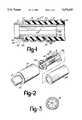
- FIG. 1is a cross-sectional view of the hose coupling of the present invention in its final assembled state showing the insert welded to the tube and the tube sleeve crimped on the hose and holding the hose onto the insert;
- FIG. 2is an exploded view of the tube coupling in accordance with the present invention and prior to the step of welding the insert to the tube;
- FIG. 3is a cross-sectional view of the insert viewed in the direction of line 3--3 of FIG. 2;
- FIG. 4is a cross-sectional elevation view of the tube coupling of the present invention showing the relative positioning of the insert within the tube just prior to the inertial welding step, and illustrating the die member within which the tube is held and the mandrel inserted within the insert for spin welding the insert onto the tube; and
- FIG. 5shows the tube and insert in accordance with the present invention after having been spin welded to one another and while the tube coupling is still within the fixed die member and prior to retracting the mandrel from the insert.
- the hose coupling 10when assembled as described in greater detail below, forms a leak-proof joint having many fluid conveying applications, though particularly suited for use in a vehicular air conditioning system.
- the hose coupling 10includes an aluminum alloyed tube 12 having a radially enlarged sleeve 14 at one end.
- a suitable alloy for tube 12is 3000 series aluminum.
- the same or higher, i.e. 5000 or 6000 series aluminumis preferred for the sleeve 14.
- An insert 16 of high strength aluminum alloysuch as 6061T6 series aluminum concentric with the tube 12 is welded at one end to the tube by means described below.
- a series of crimps 18,20,22hold a flexible hose 24 axially affixed and sealed relative to the sleeve and insert.
- a flanged nut(not shown) retained on the tube by an upset tube end flange (not shown) to allow connecting the hose and coupling t an air conditioning system component, e.g. a compressor.
- the tube 12is seen to be an integral one piece tubular construction having a radially enlarged sleeve 14 at one end as can be formed by a conventional metal forming technique such as upsetting.
- a preferred methodis to upset the end of the tube within a fixed die using an enlarged mandrel to radially expand the tube walls to the shape as shown in FIG. 2, and at the same time to form a radial stop shoulder 30 at the juncture of the tube and expanded sleeve.
- the radial shoulder 30lies generally within a plane transverse to the axis of the coupling.
- the insert 16is seen to include a radially extending collar 26.
- the collarincludes a tube end face 28 and a hose end face 32, each disposed in a plane generally transverse to the tube and collar axes.
- a tube flash pocket 34in the form of an annular groove and with the innermost radial portion of the tube end face forming a side wall of the flash pocket.
- An insert end rib 36forms the opposing side wall of the flash pocket 34.
- flash pocket 34may also serve as a locking groove.
- the remainder of the insert 16comprises a barrel portion 38 which is cylindrical and extends axially to a point where in its assembled condition it extends slightly beyond the end of the sleeve 14 to thereby act as a pilot for locating the hose in accordance with one method cf assembly.
- a series of locking ribs 40 and grooves 42Centered between the collar hose end face 32 and the end of the insert 16 is provided a series of locking ribs 40 and grooves 42.
- the ribsare equally spaced and of uniform axial length.
- the grooves 42are equally spaced and of uniform axial length with the length of the ribs and grooves being approximately equal.
- locking ribs and grooves 40,42are machined from the insert and include a bottom wall 44 parallel with the insert axis and side walls lying transversely to the insert axis.
- the insertbe strong enough to accept the radial clamp forces on it during the crimping operation. In part, this criteria is met by materials selection, i.e high strength aluminum. It is also met by maintaining wall thickness, e.g. for a 1 inch nominal size hose, the insert 16 wall thickness is 0.076-0.082 inches and the groove 42 depth is 0.008-0.015 inches.
- the insert throughbore 46is hexagonal in shape thereby providing longitudinal flats 48 about the inner circumference.
- the manner of assembling the insert to the sleeveis shown principally in FIGS. 4 and 5.
- the tubeis first located within chuck collet members 50 having a radially adjustable longitudinally directed griping surface 52 of an inner diameter sized to grip and hold the tube in fixed engagement.
- the chuck colletseach include a radially enlarged, generally concave seat portion 54 having a major diameter at the end 56 of the die member equal to or slightly larger than the outer diameter of the sleeve 14.
- the adjacent face of the radial shoulder 30conforms with the conical seat portion, i.e. the seat portion 54 includes a radius which is equal that of the corresponding radius at the juncture of the tube with the radial shoulder of the sleeve portion 14.
- Conical seat portion 54is coated with carboloy, or its equivalent, to enhance the anti-slip properties of the collet and thereby keep the sleeve 14 from slipping relative to the chuck during the spin weld operation.
- the insert 16is mounted on a mandrel 60 having a hexagonal cross-section only slightly less than that of the insert throughbore 46 and including a stop shoulder 62 abutting against the end of the insert.
- the insert and mandrelare then brought up to a desired speed and inserted into the sleeve until insert collar 26 abuts fixed sleeve radial shoulder 30.
- the mandrelis then held at this axial position and the rotational energy source is terminated.
- the sustained speed of the mandrel flywheel(not shown) is sufficient to cause the frictional welding between the collar 26 and radial shoulder 30.
- tube 12Since tube 12 is softer than insert 16, it will melt or soften at these interfaces and cause the metal to flow within the flash pocket 34, at least partially filling the flash pocket and any radial clearance between the tube and the insert end rib 36.
- the collar of the insertwill also be melted at the tube end face 28 so as to assume the configuration shown in FIG. 5.
- the mandrelwill be brought to a stop.
- the now integral tube and insert assemblyis withdrawn from the chuck and mandrel and the hose 24 may be inserted within the cavity between the barrel portion of the insert and sleeve into abutting position with the hose end face 32 of the collar 26. Then the sleeve may be crimped in the manner as shown in FIG. 1 to extrude the hose into the locking and sealing grooves 40,42 along the barrel portion 38 of the insert to complete the hose coupling assembly.
Landscapes
- Engineering & Computer Science (AREA)
- General Engineering & Computer Science (AREA)
- Mechanical Engineering (AREA)
- Joints That Cut Off Fluids, And Hose Joints (AREA)
Abstract
Description
Claims (10)
Priority Applications (1)
| Application Number | Priority Date | Filing Date | Title |
|---|---|---|---|
| US08/112,751US5370425A (en) | 1993-08-25 | 1993-08-25 | Tube-to-hose coupling (spin-sert) and method of making same |
Applications Claiming Priority (1)
| Application Number | Priority Date | Filing Date | Title |
|---|---|---|---|
| US08/112,751US5370425A (en) | 1993-08-25 | 1993-08-25 | Tube-to-hose coupling (spin-sert) and method of making same |
Publications (1)
| Publication Number | Publication Date |
|---|---|
| US5370425Atrue US5370425A (en) | 1994-12-06 |
Family
ID=22345663
Family Applications (1)
| Application Number | Title | Priority Date | Filing Date |
|---|---|---|---|
| US08/112,751Expired - LifetimeUS5370425A (en) | 1993-08-25 | 1993-08-25 | Tube-to-hose coupling (spin-sert) and method of making same |
Country Status (1)
| Country | Link |
|---|---|
| US (1) | US5370425A (en) |
Cited By (76)
| Publication number | Priority date | Publication date | Assignee | Title |
|---|---|---|---|---|
| FR2737276A1 (en)* | 1995-07-24 | 1997-01-31 | Manuli Automobile France Sa | SEALED CONNECTION DEVICE BETWEEN A RIGID TUBE TIP AND A FLEXIBLE HOSE AND METHOD FOR MANUFACTURING SUCH A DEVICE |
| WO1998058204A1 (en)* | 1997-06-19 | 1998-12-23 | Manuli Auto France | Device for sealed connection between a metal tube joining piece and a flexible pipe, and method for making same |
| US6099045A (en)* | 1997-07-30 | 2000-08-08 | Chemidro S.A.S. Di Del Pin Marta & C. | Fitting for the connection of pipes by means of pressing |
| EP1184613A2 (en) | 2000-08-29 | 2002-03-06 | The Goodyear Tire & Rubber Company | Hose coupling |
| WO2002027232A1 (en)* | 2000-09-29 | 2002-04-04 | Total Containment, Inc. | On-site spin weldable bulkhead fitment for use with fuel conveyance and containment systems |
| US20020074130A1 (en)* | 1999-02-26 | 2002-06-20 | Shell Oil Co. | Apparatus for radially expanding a tubular member |
| US6409175B1 (en)* | 1999-07-13 | 2002-06-25 | Grant Prideco, Inc. | Expandable joint connector |
| US6419278B1 (en) | 2000-05-31 | 2002-07-16 | Dana Corporation | Automotive hose coupling |
| US20020121372A1 (en)* | 1998-11-16 | 2002-09-05 | Shell Oil Co. | Isolation of subterranean zones |
| US6447020B1 (en) | 1998-03-24 | 2002-09-10 | C. F. Gomma Usa, Inc. | High-pressure integral tube coupling arrangements |
| US20020148612A1 (en)* | 1998-11-16 | 2002-10-17 | Shell Oil Co. | Isolation of subterranean zones |
| US6712154B2 (en) | 1998-11-16 | 2004-03-30 | Enventure Global Technology | Isolation of subterranean zones |
| US6725919B2 (en) | 1998-12-07 | 2004-04-27 | Shell Oil Company | Forming a wellbore casing while simultaneously drilling a wellbore |
| US20040222629A1 (en)* | 2003-05-05 | 2004-11-11 | S & S Cycle, Inc. | Fluid line connector system |
| US6823937B1 (en) | 1998-12-07 | 2004-11-30 | Shell Oil Company | Wellhead |
| US20050040646A1 (en)* | 2001-01-12 | 2005-02-24 | Harco Industries, Inc. | Flexible hydraulic brake line assembly for motor vehicle wheels |
| US6892819B2 (en) | 1998-12-07 | 2005-05-17 | Shell Oil Company | Forming a wellbore casing while simultaneously drilling a wellbore |
| US6968618B2 (en) | 1999-04-26 | 2005-11-29 | Shell Oil Company | Expandable connector |
| US20050264002A1 (en)* | 2004-05-26 | 2005-12-01 | John Clarke | Disposable clamp locator for air conditioning hose assemblies |
| US7011161B2 (en) | 1998-12-07 | 2006-03-14 | Shell Oil Company | Structural support |
| US7044218B2 (en)* | 1998-12-07 | 2006-05-16 | Shell Oil Company | Apparatus for radially expanding tubular members |
| US7048067B1 (en) | 1999-11-01 | 2006-05-23 | Shell Oil Company | Wellbore casing repair |
| US7055608B2 (en) | 1999-03-11 | 2006-06-06 | Shell Oil Company | Forming a wellbore casing while simultaneously drilling a wellbore |
| WO2006037975A3 (en)* | 2004-10-02 | 2006-06-15 | Simon Howard Corner | Elongate members such as cables and tubes, and methods of termination thereof |
| US7100685B2 (en) | 2000-10-02 | 2006-09-05 | Enventure Global Technology | Mono-diameter wellbore casing |
| US7100684B2 (en) | 2000-07-28 | 2006-09-05 | Enventure Global Technology | Liner hanger with standoffs |
| US7108061B2 (en) | 1998-12-07 | 2006-09-19 | Shell Oil Company | Expander for a tapered liner with a shoe |
| US7121352B2 (en) | 1998-11-16 | 2006-10-17 | Enventure Global Technology | Isolation of subterranean zones |
| US7168499B2 (en) | 1998-11-16 | 2007-01-30 | Shell Oil Company | Radial expansion of tubular members |
| US7168496B2 (en) | 2001-07-06 | 2007-01-30 | Eventure Global Technology | Liner hanger |
| US7172021B2 (en) | 2000-09-18 | 2007-02-06 | Shell Oil Company | Liner hanger with sliding sleeve valve |
| US7172024B2 (en) | 2000-10-02 | 2007-02-06 | Shell Oil Company | Mono-diameter wellbore casing |
| US7195064B2 (en) | 1998-12-07 | 2007-03-27 | Enventure Global Technology | Mono-diameter wellbore casing |
| US7231985B2 (en) | 1998-11-16 | 2007-06-19 | Shell Oil Company | Radial expansion of tubular members |
| US7234531B2 (en) | 1999-12-03 | 2007-06-26 | Enventure Global Technology, Llc | Mono-diameter wellbore casing |
| US7258168B2 (en) | 2001-07-27 | 2007-08-21 | Enventure Global Technology L.L.C. | Liner hanger with slip joint sealing members and method of use |
| US20070222211A1 (en)* | 2006-03-27 | 2007-09-27 | Reuter David F | Brake hose fitting and method of manufacture |
| US7290616B2 (en) | 2001-07-06 | 2007-11-06 | Enventure Global Technology, L.L.C. | Liner hanger |
| US7290605B2 (en) | 2001-12-27 | 2007-11-06 | Enventure Global Technology | Seal receptacle using expandable liner hanger |
| US7308755B2 (en) | 2003-06-13 | 2007-12-18 | Shell Oil Company | Apparatus for forming a mono-diameter wellbore casing |
| US20080001400A1 (en)* | 2006-07-03 | 2008-01-03 | Winzeler Michael D | Hose coupling |
| US7325602B2 (en) | 2000-10-02 | 2008-02-05 | Shell Oil Company | Method and apparatus for forming a mono-diameter wellbore casing |
| US7350563B2 (en) | 1999-07-09 | 2008-04-01 | Enventure Global Technology, L.L.C. | System for lining a wellbore casing |
| US7350564B2 (en) | 1998-12-07 | 2008-04-01 | Enventure Global Technology, L.L.C. | Mono-diameter wellbore casing |
| US7360591B2 (en) | 2002-05-29 | 2008-04-22 | Enventure Global Technology, Llc | System for radially expanding a tubular member |
| US7363984B2 (en) | 1998-12-07 | 2008-04-29 | Enventure Global Technology, Llc | System for radially expanding a tubular member |
| US7377326B2 (en) | 2002-08-23 | 2008-05-27 | Enventure Global Technology, L.L.C. | Magnetic impulse applied sleeve method of forming a wellbore casing |
| US7383889B2 (en) | 2001-11-12 | 2008-06-10 | Enventure Global Technology, Llc | Mono diameter wellbore casing |
| US7398832B2 (en) | 2002-06-10 | 2008-07-15 | Enventure Global Technology, Llc | Mono-diameter wellbore casing |
| US7404444B2 (en) | 2002-09-20 | 2008-07-29 | Enventure Global Technology | Protective sleeve for expandable tubulars |
| US7410000B2 (en) | 2001-01-17 | 2008-08-12 | Enventure Global Technology, Llc. | Mono-diameter wellbore casing |
| US7416027B2 (en) | 2001-09-07 | 2008-08-26 | Enventure Global Technology, Llc | Adjustable expansion cone assembly |
| US7424918B2 (en) | 2002-08-23 | 2008-09-16 | Enventure Global Technology, L.L.C. | Interposed joint sealing layer method of forming a wellbore casing |
| US7438133B2 (en) | 2003-02-26 | 2008-10-21 | Enventure Global Technology, Llc | Apparatus and method for radially expanding and plastically deforming a tubular member |
| US20080277931A1 (en)* | 2007-05-05 | 2008-11-13 | Uwe Poschenrieder | Connection for conduits and method for making it |
| US7503393B2 (en) | 2003-01-27 | 2009-03-17 | Enventure Global Technology, Inc. | Lubrication system for radially expanding tubular members |
| US7513313B2 (en) | 2002-09-20 | 2009-04-07 | Enventure Global Technology, Llc | Bottom plug for forming a mono diameter wellbore casing |
| US7516790B2 (en) | 1999-12-03 | 2009-04-14 | Enventure Global Technology, Llc | Mono-diameter wellbore casing |
| US7552776B2 (en) | 1998-12-07 | 2009-06-30 | Enventure Global Technology, Llc | Anchor hangers |
| US7571774B2 (en) | 2002-09-20 | 2009-08-11 | Eventure Global Technology | Self-lubricating expansion mandrel for expandable tubular |
| US20090256353A1 (en)* | 2008-04-09 | 2009-10-15 | Ti Group Automotive Systems, Llc | Tube To Hose Coupling |
| US7603758B2 (en) | 1998-12-07 | 2009-10-20 | Shell Oil Company | Method of coupling a tubular member |
| US7712522B2 (en) | 2003-09-05 | 2010-05-11 | Enventure Global Technology, Llc | Expansion cone and system |
| US7740076B2 (en) | 2002-04-12 | 2010-06-22 | Enventure Global Technology, L.L.C. | Protective sleeve for threaded connections for expandable liner hanger |
| US7739917B2 (en) | 2002-09-20 | 2010-06-22 | Enventure Global Technology, Llc | Pipe formability evaluation for expandable tubulars |
| US7775290B2 (en) | 2003-04-17 | 2010-08-17 | Enventure Global Technology, Llc | Apparatus for radially expanding and plastically deforming a tubular member |
| US7793721B2 (en) | 2003-03-11 | 2010-09-14 | Eventure Global Technology, Llc | Apparatus for radially expanding and plastically deforming a tubular member |
| US7819185B2 (en) | 2004-08-13 | 2010-10-26 | Enventure Global Technology, Llc | Expandable tubular |
| US7886831B2 (en) | 2003-01-22 | 2011-02-15 | Enventure Global Technology, L.L.C. | Apparatus for radially expanding and plastically deforming a tubular member |
| US7918284B2 (en) | 2002-04-15 | 2011-04-05 | Enventure Global Technology, L.L.C. | Protective sleeve for threaded connections for expandable liner hanger |
| KR101387597B1 (en)* | 2013-05-28 | 2014-04-24 | (주) 현진 | Connecting structure for refrigerant tube of air conditioner and method thereof |
| US9518689B2 (en)* | 2014-10-10 | 2016-12-13 | Swan Products, Llc | Two piece male hose coupler and method for securing a garden hose to a coupler |
| US10443771B2 (en) | 2014-09-24 | 2019-10-15 | Contitech Usa, Inc. | Crimping processes for hose assemblies and hose assemblies produced thereby |
| JP2020085140A (en)* | 2018-11-27 | 2020-06-04 | 横浜ゴム株式会社 | Hose joint fitting |
| CN113944816A (en)* | 2021-09-28 | 2022-01-18 | 上海汽车制动系统有限公司 | Design method for riveting connection reliability of hydraulic brake hose |
| US11882984B1 (en)* | 2023-03-31 | 2024-01-30 | Emerson Electric Co. | Vacuum conduit attachment tools |
Citations (12)
| Publication number | Priority date | Publication date | Assignee | Title |
|---|---|---|---|---|
| US863745A (en)* | 1906-02-20 | 1907-08-20 | Edward D Nelson | Hose-pipe-coupling end. |
| US2133313A (en)* | 1935-12-09 | 1938-10-18 | Weatherhead Co | Hose coupling and method of making same |
| US2374226A (en)* | 1942-02-04 | 1945-04-24 | Bowden Eng Ltd | Flexible hose coupling |
| US2453997A (en)* | 1946-05-02 | 1948-11-16 | Resistofiex Corp | Fitting for flexible hose |
| US2485976A (en)* | 1946-03-08 | 1949-10-25 | Aeroquip Corp | Hydraulic connector |
| US2499241A (en)* | 1947-05-10 | 1950-02-28 | Weatherhead Co | Method of making hose ends |
| US3471180A (en)* | 1967-07-31 | 1969-10-07 | Caterpillar Tractor Co | Inertia welded hose couplings |
| US3539207A (en)* | 1969-02-28 | 1970-11-10 | Resistoflex Corp | Swaged-type hose fitting and method of assembly |
| US3549180A (en)* | 1968-05-16 | 1970-12-22 | Scovill Manufacturing Co | Hose and hose coupling assembly |
| US4064614A (en)* | 1976-12-23 | 1977-12-27 | Samuel Moore And Company | Method of making an improved hose and tube coupling |
| US4548430A (en)* | 1983-04-18 | 1985-10-22 | Aeroquip Corporation | Crimped hose fitting |
| US4906030A (en)* | 1987-09-29 | 1990-03-06 | Bridgestone Flowtech Corporation | Hose fitting |
- 1993
- 1993-08-25USUS08/112,751patent/US5370425A/ennot_activeExpired - Lifetime
Patent Citations (12)
| Publication number | Priority date | Publication date | Assignee | Title |
|---|---|---|---|---|
| US863745A (en)* | 1906-02-20 | 1907-08-20 | Edward D Nelson | Hose-pipe-coupling end. |
| US2133313A (en)* | 1935-12-09 | 1938-10-18 | Weatherhead Co | Hose coupling and method of making same |
| US2374226A (en)* | 1942-02-04 | 1945-04-24 | Bowden Eng Ltd | Flexible hose coupling |
| US2485976A (en)* | 1946-03-08 | 1949-10-25 | Aeroquip Corp | Hydraulic connector |
| US2453997A (en)* | 1946-05-02 | 1948-11-16 | Resistofiex Corp | Fitting for flexible hose |
| US2499241A (en)* | 1947-05-10 | 1950-02-28 | Weatherhead Co | Method of making hose ends |
| US3471180A (en)* | 1967-07-31 | 1969-10-07 | Caterpillar Tractor Co | Inertia welded hose couplings |
| US3549180A (en)* | 1968-05-16 | 1970-12-22 | Scovill Manufacturing Co | Hose and hose coupling assembly |
| US3539207A (en)* | 1969-02-28 | 1970-11-10 | Resistoflex Corp | Swaged-type hose fitting and method of assembly |
| US4064614A (en)* | 1976-12-23 | 1977-12-27 | Samuel Moore And Company | Method of making an improved hose and tube coupling |
| US4548430A (en)* | 1983-04-18 | 1985-10-22 | Aeroquip Corporation | Crimped hose fitting |
| US4906030A (en)* | 1987-09-29 | 1990-03-06 | Bridgestone Flowtech Corporation | Hose fitting |
Cited By (130)
| Publication number | Priority date | Publication date | Assignee | Title |
|---|---|---|---|---|
| WO1997004266A1 (en)* | 1995-07-24 | 1997-02-06 | Manuli Auto France | Device forming a leak-proof connection between a rigid tube end and a flexible pipe, and method for making same |
| FR2737276A1 (en)* | 1995-07-24 | 1997-01-31 | Manuli Automobile France Sa | SEALED CONNECTION DEVICE BETWEEN A RIGID TUBE TIP AND A FLEXIBLE HOSE AND METHOD FOR MANUFACTURING SUCH A DEVICE |
| WO1998058204A1 (en)* | 1997-06-19 | 1998-12-23 | Manuli Auto France | Device for sealed connection between a metal tube joining piece and a flexible pipe, and method for making same |
| FR2764960A1 (en)* | 1997-06-19 | 1998-12-24 | Manuli Auto France | SEALED CONNECTION DEVICE BETWEEN A METAL TUBE BIT AND THE END OF A FLEXIBLE PIPE, AND METHOD OF MANUFACTURING SUCH A DEVICE |
| US6099045A (en)* | 1997-07-30 | 2000-08-08 | Chemidro S.A.S. Di Del Pin Marta & C. | Fitting for the connection of pipes by means of pressing |
| US6447020B1 (en) | 1998-03-24 | 2002-09-10 | C. F. Gomma Usa, Inc. | High-pressure integral tube coupling arrangements |
| US7108072B2 (en) | 1998-11-16 | 2006-09-19 | Shell Oil Company | Lubrication and self-cleaning system for expansion mandrel |
| US7121352B2 (en) | 1998-11-16 | 2006-10-17 | Enventure Global Technology | Isolation of subterranean zones |
| US6712154B2 (en) | 1998-11-16 | 2004-03-30 | Enventure Global Technology | Isolation of subterranean zones |
| US7246667B2 (en) | 1998-11-16 | 2007-07-24 | Shell Oil Company | Radial expansion of tubular members |
| US7270188B2 (en) | 1998-11-16 | 2007-09-18 | Shell Oil Company | Radial expansion of tubular members |
| US7299881B2 (en) | 1998-11-16 | 2007-11-27 | Shell Oil Company | Radial expansion of tubular members |
| US7357190B2 (en) | 1998-11-16 | 2008-04-15 | Shell Oil Company | Radial expansion of tubular members |
| US20020121372A1 (en)* | 1998-11-16 | 2002-09-05 | Shell Oil Co. | Isolation of subterranean zones |
| US7168499B2 (en) | 1998-11-16 | 2007-01-30 | Shell Oil Company | Radial expansion of tubular members |
| US20020148612A1 (en)* | 1998-11-16 | 2002-10-17 | Shell Oil Co. | Isolation of subterranean zones |
| US7231985B2 (en) | 1998-11-16 | 2007-06-19 | Shell Oil Company | Radial expansion of tubular members |
| US6745845B2 (en) | 1998-11-16 | 2004-06-08 | Shell Oil Company | Isolation of subterranean zones |
| US6634431B2 (en) | 1998-11-16 | 2003-10-21 | Robert Lance Cook | Isolation of subterranean zones |
| US7434618B2 (en) | 1998-12-07 | 2008-10-14 | Shell Oil Company | Apparatus for expanding a tubular member |
| US7147053B2 (en) | 1998-12-07 | 2006-12-12 | Shell Oil Company | Wellhead |
| US7195061B2 (en) | 1998-12-07 | 2007-03-27 | Shell Oil Company | Apparatus for expanding a tubular member |
| US6725919B2 (en) | 1998-12-07 | 2004-04-27 | Shell Oil Company | Forming a wellbore casing while simultaneously drilling a wellbore |
| US6739392B2 (en) | 1998-12-07 | 2004-05-25 | Shell Oil Company | Forming a wellbore casing while simultaneously drilling a wellbore |
| US7174964B2 (en) | 1998-12-07 | 2007-02-13 | Shell Oil Company | Wellhead with radially expanded tubulars |
| US6758278B2 (en) | 1998-12-07 | 2004-07-06 | Shell Oil Company | Forming a wellbore casing while simultaneously drilling a wellbore |
| US7419009B2 (en) | 1998-12-07 | 2008-09-02 | Shell Oil Company | Apparatus for radially expanding and plastically deforming a tubular member |
| US6823937B1 (en) | 1998-12-07 | 2004-11-30 | Shell Oil Company | Wellhead |
| US7198100B2 (en) | 1998-12-07 | 2007-04-03 | Shell Oil Company | Apparatus for expanding a tubular member |
| US7363984B2 (en) | 1998-12-07 | 2008-04-29 | Enventure Global Technology, Llc | System for radially expanding a tubular member |
| US6892819B2 (en) | 1998-12-07 | 2005-05-17 | Shell Oil Company | Forming a wellbore casing while simultaneously drilling a wellbore |
| US7216701B2 (en) | 1998-12-07 | 2007-05-15 | Shell Oil Company | Apparatus for expanding a tubular member |
| US7195064B2 (en) | 1998-12-07 | 2007-03-27 | Enventure Global Technology | Mono-diameter wellbore casing |
| US7357188B1 (en) | 1998-12-07 | 2008-04-15 | Shell Oil Company | Mono-diameter wellbore casing |
| US7011161B2 (en) | 1998-12-07 | 2006-03-14 | Shell Oil Company | Structural support |
| US7036582B2 (en) | 1998-12-07 | 2006-05-02 | Shell Oil Company | Expansion cone for radially expanding tubular members |
| US7665532B2 (en) | 1998-12-07 | 2010-02-23 | Shell Oil Company | Pipeline |
| US7044218B2 (en)* | 1998-12-07 | 2006-05-16 | Shell Oil Company | Apparatus for radially expanding tubular members |
| US7240729B2 (en) | 1998-12-07 | 2007-07-10 | Shell Oil Company | Apparatus for expanding a tubular member |
| US7603758B2 (en) | 1998-12-07 | 2009-10-20 | Shell Oil Company | Method of coupling a tubular member |
| US7048062B2 (en) | 1998-12-07 | 2006-05-23 | Shell Oil Company | Method of selecting tubular members |
| US7159665B2 (en) | 1998-12-07 | 2007-01-09 | Shell Oil Company | Wellbore casing |
| US7350564B2 (en) | 1998-12-07 | 2008-04-01 | Enventure Global Technology, L.L.C. | Mono-diameter wellbore casing |
| US7240728B2 (en) | 1998-12-07 | 2007-07-10 | Shell Oil Company | Expandable tubulars with a radial passage and wall portions with different wall thicknesses |
| US7077211B2 (en) | 1998-12-07 | 2006-07-18 | Shell Oil Company | Method of creating a casing in a borehole |
| US7077213B2 (en) | 1998-12-07 | 2006-07-18 | Shell Oil Company | Expansion cone for radially expanding tubular members |
| US7121337B2 (en) | 1998-12-07 | 2006-10-17 | Shell Oil Company | Apparatus for expanding a tubular member |
| US7108061B2 (en) | 1998-12-07 | 2006-09-19 | Shell Oil Company | Expander for a tapered liner with a shoe |
| US7552776B2 (en) | 1998-12-07 | 2009-06-30 | Enventure Global Technology, Llc | Anchor hangers |
| US7159667B2 (en) | 1999-02-25 | 2007-01-09 | Shell Oil Company | Method of coupling a tubular member to a preexisting structure |
| US7556092B2 (en) | 1999-02-26 | 2009-07-07 | Enventure Global Technology, Llc | Flow control system for an apparatus for radially expanding tubular members |
| US20020100594A1 (en)* | 1999-02-26 | 2002-08-01 | Shell Oil Co. | Wellbore casing |
| US20020074130A1 (en)* | 1999-02-26 | 2002-06-20 | Shell Oil Co. | Apparatus for radially expanding a tubular member |
| US6705395B2 (en) | 1999-02-26 | 2004-03-16 | Shell Oil Company | Wellbore casing |
| US7063142B2 (en) | 1999-02-26 | 2006-06-20 | Shell Oil Company | Method of applying an axial force to an expansion cone |
| US6684947B2 (en) | 1999-02-26 | 2004-02-03 | Shell Oil Company | Apparatus for radially expanding a tubular member |
| US6631769B2 (en) | 1999-02-26 | 2003-10-14 | Shell Oil Company | Method of operating an apparatus for radially expanding a tubular member |
| US20020092657A1 (en)* | 1999-02-26 | 2002-07-18 | Shell Oil Co. | Method of applying an axial force to an expansion cone |
| US7044221B2 (en) | 1999-02-26 | 2006-05-16 | Shell Oil Company | Apparatus for coupling a tubular member to a preexisting structure |
| US7040396B2 (en) | 1999-02-26 | 2006-05-09 | Shell Oil Company | Apparatus for releasably coupling two elements |
| US6966370B2 (en) | 1999-02-26 | 2005-11-22 | Shell Oil Company | Apparatus for actuating an annular piston |
| US6857473B2 (en) | 1999-02-26 | 2005-02-22 | Shell Oil Company | Method of coupling a tubular member to a preexisting structure |
| US7055608B2 (en) | 1999-03-11 | 2006-06-06 | Shell Oil Company | Forming a wellbore casing while simultaneously drilling a wellbore |
| US7438132B2 (en) | 1999-03-11 | 2008-10-21 | Shell Oil Company | Concentric pipes expanded at the pipe ends and method of forming |
| US6968618B2 (en) | 1999-04-26 | 2005-11-29 | Shell Oil Company | Expandable connector |
| US7350563B2 (en) | 1999-07-09 | 2008-04-01 | Enventure Global Technology, L.L.C. | System for lining a wellbore casing |
| US6409175B1 (en)* | 1999-07-13 | 2002-06-25 | Grant Prideco, Inc. | Expandable joint connector |
| US7048067B1 (en) | 1999-11-01 | 2006-05-23 | Shell Oil Company | Wellbore casing repair |
| US7234531B2 (en) | 1999-12-03 | 2007-06-26 | Enventure Global Technology, Llc | Mono-diameter wellbore casing |
| US7516790B2 (en) | 1999-12-03 | 2009-04-14 | Enventure Global Technology, Llc | Mono-diameter wellbore casing |
| EP1162399A3 (en)* | 2000-05-31 | 2003-09-17 | Dana Corporation | Automotive hose coupling |
| US6419278B1 (en) | 2000-05-31 | 2002-07-16 | Dana Corporation | Automotive hose coupling |
| US7100684B2 (en) | 2000-07-28 | 2006-09-05 | Enventure Global Technology | Liner hanger with standoffs |
| US6394506B1 (en) | 2000-08-29 | 2002-05-28 | The Goodyear Tire & Rubber Company | Hose coupling |
| EP1184613A2 (en) | 2000-08-29 | 2002-03-06 | The Goodyear Tire & Rubber Company | Hose coupling |
| US7172021B2 (en) | 2000-09-18 | 2007-02-06 | Shell Oil Company | Liner hanger with sliding sleeve valve |
| WO2002027232A1 (en)* | 2000-09-29 | 2002-04-04 | Total Containment, Inc. | On-site spin weldable bulkhead fitment for use with fuel conveyance and containment systems |
| US7100685B2 (en) | 2000-10-02 | 2006-09-05 | Enventure Global Technology | Mono-diameter wellbore casing |
| US7363691B2 (en) | 2000-10-02 | 2008-04-29 | Shell Oil Company | Method and apparatus for forming a mono-diameter wellbore casing |
| US7363690B2 (en) | 2000-10-02 | 2008-04-29 | Shell Oil Company | Method and apparatus for forming a mono-diameter wellbore casing |
| US7172024B2 (en) | 2000-10-02 | 2007-02-06 | Shell Oil Company | Mono-diameter wellbore casing |
| US7146702B2 (en) | 2000-10-02 | 2006-12-12 | Shell Oil Company | Method and apparatus for forming a mono-diameter wellbore casing |
| US7325602B2 (en) | 2000-10-02 | 2008-02-05 | Shell Oil Company | Method and apparatus for forming a mono-diameter wellbore casing |
| US7172019B2 (en) | 2000-10-02 | 2007-02-06 | Shell Oil Company | Method and apparatus for forming a mono-diameter wellbore casing |
| US7204007B2 (en) | 2000-10-02 | 2007-04-17 | Shell Oil Company | Method and apparatus for forming a mono-diameter wellbore casing |
| US7201223B2 (en) | 2000-10-02 | 2007-04-10 | Shell Oil Company | Method and apparatus for forming a mono-diameter wellbore casing |
| US20050040646A1 (en)* | 2001-01-12 | 2005-02-24 | Harco Industries, Inc. | Flexible hydraulic brake line assembly for motor vehicle wheels |
| US7410000B2 (en) | 2001-01-17 | 2008-08-12 | Enventure Global Technology, Llc. | Mono-diameter wellbore casing |
| US7290616B2 (en) | 2001-07-06 | 2007-11-06 | Enventure Global Technology, L.L.C. | Liner hanger |
| US7168496B2 (en) | 2001-07-06 | 2007-01-30 | Eventure Global Technology | Liner hanger |
| US7258168B2 (en) | 2001-07-27 | 2007-08-21 | Enventure Global Technology L.L.C. | Liner hanger with slip joint sealing members and method of use |
| US7416027B2 (en) | 2001-09-07 | 2008-08-26 | Enventure Global Technology, Llc | Adjustable expansion cone assembly |
| US7559365B2 (en) | 2001-11-12 | 2009-07-14 | Enventure Global Technology, Llc | Collapsible expansion cone |
| US7383889B2 (en) | 2001-11-12 | 2008-06-10 | Enventure Global Technology, Llc | Mono diameter wellbore casing |
| US7290605B2 (en) | 2001-12-27 | 2007-11-06 | Enventure Global Technology | Seal receptacle using expandable liner hanger |
| US7740076B2 (en) | 2002-04-12 | 2010-06-22 | Enventure Global Technology, L.L.C. | Protective sleeve for threaded connections for expandable liner hanger |
| US7918284B2 (en) | 2002-04-15 | 2011-04-05 | Enventure Global Technology, L.L.C. | Protective sleeve for threaded connections for expandable liner hanger |
| US7360591B2 (en) | 2002-05-29 | 2008-04-22 | Enventure Global Technology, Llc | System for radially expanding a tubular member |
| US7398832B2 (en) | 2002-06-10 | 2008-07-15 | Enventure Global Technology, Llc | Mono-diameter wellbore casing |
| US7424918B2 (en) | 2002-08-23 | 2008-09-16 | Enventure Global Technology, L.L.C. | Interposed joint sealing layer method of forming a wellbore casing |
| US7377326B2 (en) | 2002-08-23 | 2008-05-27 | Enventure Global Technology, L.L.C. | Magnetic impulse applied sleeve method of forming a wellbore casing |
| US7571774B2 (en) | 2002-09-20 | 2009-08-11 | Eventure Global Technology | Self-lubricating expansion mandrel for expandable tubular |
| US7404444B2 (en) | 2002-09-20 | 2008-07-29 | Enventure Global Technology | Protective sleeve for expandable tubulars |
| US7513313B2 (en) | 2002-09-20 | 2009-04-07 | Enventure Global Technology, Llc | Bottom plug for forming a mono diameter wellbore casing |
| US7739917B2 (en) | 2002-09-20 | 2010-06-22 | Enventure Global Technology, Llc | Pipe formability evaluation for expandable tubulars |
| US7886831B2 (en) | 2003-01-22 | 2011-02-15 | Enventure Global Technology, L.L.C. | Apparatus for radially expanding and plastically deforming a tubular member |
| US7503393B2 (en) | 2003-01-27 | 2009-03-17 | Enventure Global Technology, Inc. | Lubrication system for radially expanding tubular members |
| US7438133B2 (en) | 2003-02-26 | 2008-10-21 | Enventure Global Technology, Llc | Apparatus and method for radially expanding and plastically deforming a tubular member |
| US7793721B2 (en) | 2003-03-11 | 2010-09-14 | Eventure Global Technology, Llc | Apparatus for radially expanding and plastically deforming a tubular member |
| US7775290B2 (en) | 2003-04-17 | 2010-08-17 | Enventure Global Technology, Llc | Apparatus for radially expanding and plastically deforming a tubular member |
| US20040222629A1 (en)* | 2003-05-05 | 2004-11-11 | S & S Cycle, Inc. | Fluid line connector system |
| US7308755B2 (en) | 2003-06-13 | 2007-12-18 | Shell Oil Company | Apparatus for forming a mono-diameter wellbore casing |
| US7712522B2 (en) | 2003-09-05 | 2010-05-11 | Enventure Global Technology, Llc | Expansion cone and system |
| US7090255B2 (en) | 2004-05-26 | 2006-08-15 | Atco Products, Inc. | Disposable clamp locator for air conditioning hose assemblies |
| US20050264002A1 (en)* | 2004-05-26 | 2005-12-01 | John Clarke | Disposable clamp locator for air conditioning hose assemblies |
| US7819185B2 (en) | 2004-08-13 | 2010-10-26 | Enventure Global Technology, Llc | Expandable tubular |
| WO2006037975A3 (en)* | 2004-10-02 | 2006-06-15 | Simon Howard Corner | Elongate members such as cables and tubes, and methods of termination thereof |
| US20070222211A1 (en)* | 2006-03-27 | 2007-09-27 | Reuter David F | Brake hose fitting and method of manufacture |
| US8096588B2 (en)* | 2006-07-03 | 2012-01-17 | Winzeler Stamping Company | Hose coupling |
| US20080001400A1 (en)* | 2006-07-03 | 2008-01-03 | Winzeler Michael D | Hose coupling |
| US20080277931A1 (en)* | 2007-05-05 | 2008-11-13 | Uwe Poschenrieder | Connection for conduits and method for making it |
| US20090256353A1 (en)* | 2008-04-09 | 2009-10-15 | Ti Group Automotive Systems, Llc | Tube To Hose Coupling |
| US7708318B2 (en)* | 2008-04-09 | 2010-05-04 | Ti Group Automotive Systems, Llc | Tube to hose coupling |
| CN101555968B (en)* | 2008-04-09 | 2013-05-22 | Ti集团机车系统公司 | Tube-to-hose coupling |
| KR101387597B1 (en)* | 2013-05-28 | 2014-04-24 | (주) 현진 | Connecting structure for refrigerant tube of air conditioner and method thereof |
| US10443771B2 (en) | 2014-09-24 | 2019-10-15 | Contitech Usa, Inc. | Crimping processes for hose assemblies and hose assemblies produced thereby |
| US9518689B2 (en)* | 2014-10-10 | 2016-12-13 | Swan Products, Llc | Two piece male hose coupler and method for securing a garden hose to a coupler |
| JP2020085140A (en)* | 2018-11-27 | 2020-06-04 | 横浜ゴム株式会社 | Hose joint fitting |
| CN113944816A (en)* | 2021-09-28 | 2022-01-18 | 上海汽车制动系统有限公司 | Design method for riveting connection reliability of hydraulic brake hose |
| US11882984B1 (en)* | 2023-03-31 | 2024-01-30 | Emerson Electric Co. | Vacuum conduit attachment tools |
Similar Documents
| Publication | Publication Date | Title |
|---|---|---|
| US5370425A (en) | Tube-to-hose coupling (spin-sert) and method of making same | |
| US6654995B1 (en) | Method for joining tubular members | |
| US5417461A (en) | Tube-to-hose coupling (crimp-sert) and method of making same | |
| US5297586A (en) | Flexible metal hose assembly incorporating modified braid ring with annular member having tools flats | |
| US5387016A (en) | Tubular coupling | |
| US6598281B2 (en) | Method for mounting a metal body on the measuring tube of a Coriolis mass flowmeter | |
| US3787945A (en) | Method of fabricating an expanded tube connection | |
| US3589752A (en) | Mechanical joined hose coupling of extruded components | |
| US5419028A (en) | Method of making a hose coupling | |
| CA1105960A (en) | Tube-to-tube joint and method | |
| US4765661A (en) | Union joint assembly | |
| US5499439A (en) | Method of forming a flexible metal hose connector | |
| IE46565B1 (en) | Fusion welding plastics pipe end portions | |
| US3838592A (en) | Hose end fittings and inserts therefor | |
| US7062834B2 (en) | Process of forming two beads | |
| US5833280A (en) | Mechanical joint | |
| US6808210B1 (en) | Drill pipe with upset ends having constant wall thickness and method for making same | |
| US4381594A (en) | Method of cold forming coupling shell | |
| US3977710A (en) | Tube fitting assembly | |
| US4365669A (en) | Non-solvent bonded plastic well screen assembly | |
| US5293679A (en) | Method of connecting two pipes | |
| US5321968A (en) | One piece tubing connector and method of forming same | |
| US4126929A (en) | Method of tube fitting assembly with shoulder means | |
| US4135739A (en) | Off-set welding ring | |
| US5240168A (en) | Method for making a composite to carbon steel joint |
Legal Events
| Date | Code | Title | Description |
|---|---|---|---|
| AS | Assignment | Owner name:S&H FABRICATING AND ENGINEERING, INC., FLORIDA Free format text:ASSIGNMENT OF ASSIGNORS INTEREST;ASSIGNORS:DOUGHERTY, MICHAEL L.;WARNER, NORMAN E.;REEL/FRAME:006678/0238 Effective date:19930810 | |
| STCF | Information on status: patent grant | Free format text:PATENTED CASE | |
| RR | Request for reexamination filed | Effective date:19940912 | |
| FEPP | Fee payment procedure | Free format text:PAYOR NUMBER ASSIGNED (ORIGINAL EVENT CODE: ASPN); ENTITY STATUS OF PATENT OWNER: LARGE ENTITY | |
| FPAY | Fee payment | Year of fee payment:4 | |
| AS | Assignment | Owner name:TI GROUP AUTOMOTIVE SYSTEMS CORPORATION, MICHIGAN Free format text:CHANGE OF NAME;ASSIGNOR:BUNDY CORPORATION;REEL/FRAME:010859/0541 Effective date:19991012 Owner name:BUNDY CORPORATION, MICHIGAN Free format text:MERGER;ASSIGNOR:S&H RFABRICATING AND ENGINEERING, INC.;REEL/FRAME:010871/0349 Effective date:19990101 | |
| AS | Assignment | Owner name:TI GROUP AUTOMOTIVE SYSTEMS, LLC, MICHIGAN Free format text:MERGER;ASSIGNOR:TI GROUP AUTOMOTIVE SYSTEMS CORPORATION;REEL/FRAME:012407/0436 Effective date:20010625 | |
| FPAY | Fee payment | Year of fee payment:8 | |
| FPAY | Fee payment | Year of fee payment:12 | |
| AS | Assignment | Owner name:JPMORGAN CHASE BANK, N.A., NEW YORK Free format text:SECURITY AGREEMENT;ASSIGNORS:HANIL USA, L.L.C.;TI AUTOMOTIVE, L.L.C.;TI GROUP AUTOMOTIVE SYSTEMS, L.L.C.;REEL/FRAME:019733/0933 Effective date:20070629 Owner name:JPMORGAN CHASE BANK, N.A.,NEW YORK Free format text:SECURITY AGREEMENT;ASSIGNORS:HANIL USA, L.L.C.;TI AUTOMOTIVE, L.L.C.;TI GROUP AUTOMOTIVE SYSTEMS, L.L.C.;REEL/FRAME:019733/0933 Effective date:20070629 | |
| AS | Assignment | Owner name:WILMINGTON TRUST (LONDON) LIMITED,UNITED KINGDOM Free format text:ASSIGNMENT OF SECURITY INTEREST;ASSIGNOR:JP MORGAN CHASE BANK, N.A.;REEL/FRAME:024055/0633 Effective date:20100208 Owner name:WILMINGTON TRUST (LONDON) LIMITED, UNITED KINGDOM Free format text:ASSIGNMENT OF SECURITY INTEREST;ASSIGNOR:JP MORGAN CHASE BANK, N.A.;REEL/FRAME:024055/0633 Effective date:20100208 | |
| AS | Assignment | Owner name:CITIBANK N.A., DELAWARE Free format text:TERM PATENT SECURITY AGREEMENT;ASSIGNOR:TI GROUP AUTOMOTIVE SYSTEMS, L.L.C.;REEL/FRAME:024896/0057 Effective date:20100825 Owner name:TI AUTOMOTIVE, L.L.C., MICHIGAN Free format text:RELEASE AND TERMINATION OF PATENT SECURITY INTEREST;ASSIGNOR:WILMINGTON TRUST (LONDON) LIMITED (AS SUCCESSOR IN INTEREST TO JP MORGAN CHASE BANK, N.A.);REEL/FRAME:024891/0671 Effective date:20100825 Owner name:HANIL USA, L.L.C., MICHIGAN Free format text:RELEASE AND TERMINATION OF PATENT SECURITY INTEREST;ASSIGNOR:WILMINGTON TRUST (LONDON) LIMITED (AS SUCCESSOR IN INTEREST TO JP MORGAN CHASE BANK, N.A.);REEL/FRAME:024891/0671 Effective date:20100825 Owner name:TI GROUP AUTOMOTIVE SYSTEMS, L.L.C., MICHIGAN Free format text:RELEASE AND TERMINATION OF PATENT SECURITY INTEREST;ASSIGNOR:WILMINGTON TRUST (LONDON) LIMITED (AS SUCCESSOR IN INTEREST TO JP MORGAN CHASE BANK, N.A.);REEL/FRAME:024891/0671 Effective date:20100825 Owner name:CITIBANK N.A., DELAWARE Free format text:ABL PATENT SECURITY AGREEMENT;ASSIGNOR:TI GROUP AUTOMOTIVE SYSTEMS, L.L.C.;REEL/FRAME:024895/0956 Effective date:20100825 | |
| AS | Assignment | Owner name:TI GROUP AUTOMOTIVE SYSTEMS, L.L.C., MICHIGAN Free format text:RELEASE BY SECURED PARTY;ASSIGNOR:CITIBANK, N.A.;REEL/FRAME:027865/0016 Effective date:20120314 Owner name:JPMORGAN CHASE BANK, N.A., NEW YORK Free format text:SECURITY AGREEMENT;ASSIGNORS:TI GROUP AUTOMOTIVE SYSTEMS, L.L.C.;TI AUTOMOTIVE LIMITED;TI AUTOMOTIVE CANADA, INC.;AND OTHERS;REEL/FRAME:027864/0968 Effective date:20120314 | |
| AS | Assignment | Owner name:TI AUTOMOTIVE, L.L.C., MICHIGAN Free format text:TERMINATION AND RELEASE;ASSIGNOR:JPMORGAN CHASE BANK, N.A., AS ADMINISTRATIVE AGENT;REEL/FRAME:036013/0775 Effective date:20150630 Owner name:TI AUTOMOTIVE CANADA, INC., CANADA Free format text:TERMINATION AND RELEASE;ASSIGNOR:JPMORGAN CHASE BANK, N.A., AS ADMINISTRATIVE AGENT;REEL/FRAME:036013/0775 Effective date:20150630 Owner name:TI AUTOMOTIVE LIMITED, UNITED KINGDOM Free format text:TERMINATION AND RELEASE;ASSIGNOR:JPMORGAN CHASE BANK, N.A., AS ADMINISTRATIVE AGENT;REEL/FRAME:036013/0775 Effective date:20150630 Owner name:TI GROUP AUTOMOTIVE SYSTEMS, L.L.C., MICHIGAN Free format text:TERMINATION AND RELEASE;ASSIGNOR:JPMORGAN CHASE BANK, N.A., AS ADMINISTRATIVE AGENT;REEL/FRAME:036013/0775 Effective date:20150630 Owner name:TI GROUP AUTOMOTIVE SYSTEMS S DE R.L. DE C.V., MEX Free format text:TERMINATION AND RELEASE;ASSIGNOR:JPMORGAN CHASE BANK, N.A., AS ADMINISTRATIVE AGENT;REEL/FRAME:036013/0775 Effective date:20150630 Owner name:HANIL USA L.L.C., ALABAMA Free format text:TERMINATION AND RELEASE;ASSIGNOR:JPMORGAN CHASE BANK, N.A., AS ADMINISTRATIVE AGENT;REEL/FRAME:036013/0775 Effective date:20150630 |