US5368596A - Augmented awl for creating channels in human bone tissue - Google Patents
Augmented awl for creating channels in human bone tissueDownload PDFInfo
- Publication number
- US5368596A US5368596AUS08/064,364US6436493AUS5368596AUS 5368596 AUS5368596 AUS 5368596AUS 6436493 AUS6436493 AUS 6436493AUS 5368596 AUS5368596 AUS 5368596A
- Authority
- US
- United States
- Prior art keywords
- pair
- lever
- jaws
- handles
- lever pair
- Prior art date
- Legal status (The legal status is an assumption and is not a legal conclusion. Google has not performed a legal analysis and makes no representation as to the accuracy of the status listed.)
- Expired - Lifetime
Links
- 210000000988bone and boneAnatomy0.000titleclaimsabstractdescription25
- 230000003190augmentative effectEffects0.000titledescription8
- 210000000080chela (arthropods)Anatomy0.000claimsabstractdescription21
- 238000001356surgical procedureMethods0.000claimsabstractdescription14
- 229910001220stainless steelInorganic materials0.000claims2
- 239000010935stainless steelSubstances0.000claims2
- 210000003205muscleAnatomy0.000abstractdescription6
- 210000002435tendonAnatomy0.000abstractdescription5
- 150000001875compoundsChemical class0.000abstractdescription3
- 210000003041ligamentAnatomy0.000abstractdescription3
- 238000000926separation methodMethods0.000abstractdescription2
- 230000000694effectsEffects0.000description9
- 238000000034methodMethods0.000description7
- 239000003638chemical reducing agentSubstances0.000description5
- 230000008859changeEffects0.000description3
- 230000006835compressionEffects0.000description3
- 238000007906compressionMethods0.000description3
- 210000003127kneeAnatomy0.000description3
- 206010052428WoundDiseases0.000description2
- 230000009471actionEffects0.000description2
- 230000005465channelingEffects0.000description2
- 238000003780insertionMethods0.000description2
- 230000037431insertionEffects0.000description2
- 238000012423maintenanceMethods0.000description2
- 230000008439repair processEffects0.000description2
- 210000000513rotator cuffAnatomy0.000description2
- 208000027418Wounds and injuryDiseases0.000description1
- 230000003466anti-cipated effectEffects0.000description1
- 230000008901benefitEffects0.000description1
- 210000002758humerusAnatomy0.000description1
- 208000014674injuryDiseases0.000description1
- 230000007246mechanismEffects0.000description1
- 238000012986modificationMethods0.000description1
- 230000004048modificationEffects0.000description1
- 238000011084recoveryMethods0.000description1
- 210000004872soft tissueAnatomy0.000description1
- 239000003356suture materialSubstances0.000description1
- 230000008733traumaEffects0.000description1
Images


Classifications
- A—HUMAN NECESSITIES
- A61—MEDICAL OR VETERINARY SCIENCE; HYGIENE
- A61B—DIAGNOSIS; SURGERY; IDENTIFICATION
- A61B17/00—Surgical instruments, devices or methods
- A61B17/32—Surgical cutting instruments
- A61B17/320016—Endoscopic cutting instruments, e.g. arthroscopes, resectoscopes
- A—HUMAN NECESSITIES
- A61—MEDICAL OR VETERINARY SCIENCE; HYGIENE
- A61B—DIAGNOSIS; SURGERY; IDENTIFICATION
- A61B17/00—Surgical instruments, devices or methods
- A61B17/16—Instruments for performing osteoclasis; Drills or chisels for bones; Trepans
- A61B17/1604—Chisels; Rongeurs; Punches; Stamps
- A61B17/1606—Chisels; Rongeurs; Punches; Stamps of forceps type, i.e. having two jaw elements moving relative to each other
- A—HUMAN NECESSITIES
- A61—MEDICAL OR VETERINARY SCIENCE; HYGIENE
- A61B—DIAGNOSIS; SURGERY; IDENTIFICATION
- A61B17/00—Surgical instruments, devices or methods
- A61B17/28—Surgical forceps
- A61B17/2804—Surgical forceps with two or more pivotal connections
- A—HUMAN NECESSITIES
- A61—MEDICAL OR VETERINARY SCIENCE; HYGIENE
- A61B—DIAGNOSIS; SURGERY; IDENTIFICATION
- A61B17/00—Surgical instruments, devices or methods
- A61B17/28—Surgical forceps
- A61B17/2812—Surgical forceps with a single pivotal connection
- A61B17/282—Jaws
- A—HUMAN NECESSITIES
- A61—MEDICAL OR VETERINARY SCIENCE; HYGIENE
- A61B—DIAGNOSIS; SURGERY; IDENTIFICATION
- A61B17/00—Surgical instruments, devices or methods
- A61B17/28—Surgical forceps
- A61B17/2812—Surgical forceps with a single pivotal connection
- A61B17/2841—Handles
- A61B2017/2845—Handles with a spring pushing the handle back
- A—HUMAN NECESSITIES
- A61—MEDICAL OR VETERINARY SCIENCE; HYGIENE
- A61F—FILTERS IMPLANTABLE INTO BLOOD VESSELS; PROSTHESES; DEVICES PROVIDING PATENCY TO, OR PREVENTING COLLAPSING OF, TUBULAR STRUCTURES OF THE BODY, e.g. STENTS; ORTHOPAEDIC, NURSING OR CONTRACEPTIVE DEVICES; FOMENTATION; TREATMENT OR PROTECTION OF EYES OR EARS; BANDAGES, DRESSINGS OR ABSORBENT PADS; FIRST-AID KITS
- A61F2/00—Filters implantable into blood vessels; Prostheses, i.e. artificial substitutes or replacements for parts of the body; Appliances for connecting them with the body; Devices providing patency to, or preventing collapsing of, tubular structures of the body, e.g. stents
- A61F2/02—Prostheses implantable into the body
- A61F2/08—Muscles; Tendons; Ligaments
- A61F2/0805—Implements for inserting tendons or ligaments
Definitions
- a device for locating a channel and for channeling through living human bone tissueand more particularly a device using an augmented awl with a pair of semicircular pincer comprising jaws thereon.
- a channel or tunnelis created through the bone through which suture material can be passed.
- a method of creating a channelemploys a pick-type device located at the distal end of a rod.
- problems involved with a pickinclude the inability to determine exactly where it will emerge when forced through the bone.
- the "pick method" of creating a channelis, at best, a method of estimating the radius of curvature of the channel and the ultimate end point of the channel where it emerges through the surface of the bone.
- the device of the present inventionprovides for just such an instrument. More specifically, the device of the present invention provides for a low profile compound lever awl with a pair of semicircular pincer jaws. The use of such a tool allows for a low profile and therefore ease of insertion into the patient, as through a cannula, while also providing for a device to locate and fix the end points of the channel to be created and to positively determine the path of such a channel between the end points.
- the present invention shown in the specifications and described in the claimsprovides a device for creating a channel through bone tissue for suturing ligaments, tendons, or muscle tissues to the bone during arthroscopic surgery.
- the device of the present inventioncomprises a pair of compound levers with handles at a first end and a pair of semicircular pincers at the second end.
- the device of the present inventionallows for inserting pincer jaws and the body of the device through a cannula adjacent to the bone to be channeled, opening the jaws to a desired separation by locating the end points of the semicircular pincers against the bone to be channeled and then compressing the jaws.
- the device of the present inventionprovides for an instrument to create a channel in living human bone tissue.
- FIG. 1is a side elevational view of the augmented awl of the present invention with the pincers in an open position against the bone to be channeled.
- FIG. 2is a side elevational view of the augmented awl in the present invention with the pincers in the closed position as they would be following channeling through the bone.
- FIG. 3is a detail view of the means biasing the handles of the augmented awl apart.
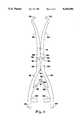
- FIG. 4is a side view of another preferred embodiment of the present invention illustrating a second lever pair having resistance arms substantially longer than effort arms.
- FIGS. 1 and 2illustrate the augmented awl (10) of the present invention.
- Augmented awl (10)is comprised of first lever pair (12) and second lever pair (14) connected to one another at articulation points (16a) and (16b).
- First lever pair (12)is comprised of handles (18a) and (18b) which are identically dimensioned and which are integral with resistance arms (20a) and (20b).
- Handles (18a) and (18b) of first lever pair (12)articulate at first joint (22).
- Handles (18a) and (18b)have removed ends (24a) and (24b) respectively.
- bias means (26)which may be comprised of leaf springs (28a) and (28b).
- Leaf springs (28a) and (28b)are fixed at one end to the inside surface of handles (18a) and (18b).
- At the removed ends of eachare a slot (29a) in leaf spring (28a) and a tongue (29b) in leaf spring (28b), the tongue engaging the slot (29a) as illustrated in FIG. 3.
- first lever pair (12)is in effect a set of shears at which a compression force applied at removed ends (24a) and (24b) causes articulation at first joint (22) and a force rotating resistance arms (20a) and (20b) outward or apart.
- second lever pair (14)is comprised of handle (32a) and (32b) articulating at second joint (34) with resistance arms (36a) and (36b). More particularly, it can be seen that resistance arms (36a) and (36b) are shaped in the form of semicircular pincers which operate together as jaws such that as removed ends (24a) and (24b) are compressed, semicircular pincers (36a) and (36b), with sharp, spike-like tips (37a) and (37b), also compress or close to overcome the resistance generated by the bone.
- tips (37a) and (37b)are shaped with beveled edges so that when they close one upon the other, they are slightly adjacent to one another rather than meeting tip to tip, so the tips slightly override (on the beveled edge) one another. This provides for maintenance of sharp tips and for maintenance of uniform width of the bone tunnel.
- semicircular pincershave a generally matching and uniform radius of curvature "r" which may be of several sizes preselected by the surgeon depending upon the requirements for the surgical operation.
- Preferred radii of curvatureinclude: 3/4 cm., 11/8 cm., and 11/2 cm., or preferably in the range of 1/2 cm. to 2 cm.
- a distance between tips in the range of 1/2 cm. to 4 cm.is preferable measured when the jaws are in their open position, this range suitable to locate the end points of the tunnel on most adults.
- second lever pair (14)provides a means for extending the distance between the applied force at (24a) and (24b) and pincers at resistance arms (36a) and (36b), yet retaining a low profile over the distance through which a portion of the instrument traverses the patient's soft tissues (muscle, fat).
- the accompanying tableillustrates the combined ideal mechanical advantage resulting on both the force applied on the handles and the distance the handles move when changing the length of the component arms of the first and second pairs of levers.
- This tableis intended to give the practitioner a summary of the various lengths of lever arms and their effect on distance and force transmitted from handles through to the jaws of the device.
- the primary function of the device of the present inventionis to maintain a low profile instrument while being capable of transmitting a compressive force from the handles through jaws at a removed end thereof.
- a preferred embodiment of the present inventionis provided with a second lever pair having resistance arms several times longer than the effort arms.
- This specific embodimentapproximates situation a+f, here with E 1 /R 1 , about equal to 4 to 5, and E 2 /R 2 about equal to 1/4 to 1/5, the overall effect being to merely transmit force and distance unchanged.
- awl (10)may be provided with stop means (38a) and (38b). Stop means (38a) and (38b) are provided to prevent the further compression of handles (24a) and (24b) after the jaws reach the closed position. The surgeon will be unable to visually observe the action of the jaw tips as they close as this action will occur inside the bone.
- Stop means (38a) and (38b)are comprised of similarly dimensioned posts oppositely attached to the inside of handles (24a) and (24b). The removed ends of the posts contact as tips (24a) and (24b) contact. This prevents tips (24a) and (24b) from substantially overriding one another.
- the instrumentis inserted through a speculum sheath or cannula in a position with the jaws closed as illustrated in FIG. 2. This will produce the lowest profile to allow for insertion through the cannula.
- the surgeoncan open the jaws, now past the open mouth of the cannula, and locate the end points of the bone to be channeled, as determined by the requirements of the surgery. With the jaws fully open, the leaf-spring mechanism automatically determines the two end points of the Bone Channel.
- the surgeonwill apply a gradual compressive force at the handles of the first lever pair, which handles extend well beyond the open mouth cannula and are thus easily grasped by the surgeon.
- the compressive force applied to the handleswill cause the tips of the semicircular pincers to pierce the cortex of the bone. Further compression of the removed ends while slowly and gently working the awl in a side to side manner, will provide sufficient force to bring the tips of the pincers together and thereby create the channel. Slowly releasing the compressive force with allow the pincers to withdraw from the channel they have created.
- the surgeonBefore removal through the cannula, the surgeon will compress the handles to provide for the lowered profile and removal through the cannula.
Landscapes
- Health & Medical Sciences (AREA)
- Surgery (AREA)
- Life Sciences & Earth Sciences (AREA)
- Medical Informatics (AREA)
- Animal Behavior & Ethology (AREA)
- Engineering & Computer Science (AREA)
- Biomedical Technology (AREA)
- Heart & Thoracic Surgery (AREA)
- Veterinary Medicine (AREA)
- Molecular Biology (AREA)
- Nuclear Medicine, Radiotherapy & Molecular Imaging (AREA)
- General Health & Medical Sciences (AREA)
- Public Health (AREA)
- Orthopedic Medicine & Surgery (AREA)
- Dentistry (AREA)
- Oral & Maxillofacial Surgery (AREA)
- Ophthalmology & Optometry (AREA)
- Surgical Instruments (AREA)
Abstract
Description
This is a continuation of copending application(s) Ser. No. 07/853,123 filed on Mar. 18, 1992, now abandoned.
This application incorporates by reference the specification and drawings of U.S. patent application Ser. No. 07/686,132 filed Apr. 16, 1991.
A device for locating a channel and for channeling through living human bone tissue, and more particularly a device using an augmented awl with a pair of semicircular pincer comprising jaws thereon.
While arthroscopic surgery involving the knee has been practiced for quite some time, arthroscopic surgery on other joints, such as the shoulder, is a relatively new endeavor. A number of problems are encountered in such surgery that are not encountered in arthroscopic surgery of the knee. These problems include working through a thicker layer of skin and muscle tissue than is found in the knee. Other problems include reattaching torn tendons, ligaments, or muscle tissue to bone and the problem of having to work in close proximity to neurovascular structures.
Thus, with such problems, there arises a need for instruments designed to be insertable through a small incision, yet able to reach a remote location at which the repair is to be performed. For example, with the recent advent of arthroscopic surgery to the shoulder, such as in the repair of torn rotator cuff tendons, a new set of instruments and procedures is helpful. As part of the procedure disclosed in the '132 application, a channel (or tunnel) is to be formed in the greater tuberosity of the humerus (shoulder). The traditional method of performing such surgery involves open surgery requiring a large longitudinal wound across the operation site, working through the muscles and exposing the injured tendon. Arthroscopic surgery is preferred, however, especially in view of the quicker recovery time and lessened trauma to the patient. However, arthroscopic surgery requires instruments having a low profile, which are capable of being partially inserted through small incisions in the patient to perform a variety of functions at the operation site located remotely within the patient's body.
In repairing a torn rotator cuff, a channel or tunnel is created through the bone through which suture material can be passed. Presently, such a method of creating a channel employs a pick-type device located at the distal end of a rod. However, problems involved with a pick include the inability to determine exactly where it will emerge when forced through the bone. The "pick method" of creating a channel is, at best, a method of estimating the radius of curvature of the channel and the ultimate end point of the channel where it emerges through the surface of the bone.
What is needed is a device for locating both end points and creating a channel of predetermined radius of curvature between those twin points that can be inserted through a small puncture wound for arthroscopic use. The device of the present invention provides for just such an instrument. More specifically, the device of the present invention provides for a low profile compound lever awl with a pair of semicircular pincer jaws. The use of such a tool allows for a low profile and therefore ease of insertion into the patient, as through a cannula, while also providing for a device to locate and fix the end points of the channel to be created and to positively determine the path of such a channel between the end points.
The present invention shown in the specifications and described in the claims provides a device for creating a channel through bone tissue for suturing ligaments, tendons, or muscle tissues to the bone during arthroscopic surgery.
The device of the present invention comprises a pair of compound levers with handles at a first end and a pair of semicircular pincers at the second end.
The device of the present invention allows for inserting pincer jaws and the body of the device through a cannula adjacent to the bone to be channeled, opening the jaws to a desired separation by locating the end points of the semicircular pincers against the bone to be channeled and then compressing the jaws.
Thus, the device of the present invention provides for an instrument to create a channel in living human bone tissue.
FIG. 1 is a side elevational view of the augmented awl of the present invention with the pincers in an open position against the bone to be channeled.
FIG. 2 is a side elevational view of the augmented awl in the present invention with the pincers in the closed position as they would be following channeling through the bone.
FIG. 3 is a detail view of the means biasing the handles of the augmented awl apart.
FIG. 4 is a side view of another preferred embodiment of the present invention illustrating a second lever pair having resistance arms substantially longer than effort arms.
FIGS. 1 and 2 illustrate the augmented awl (10) of the present invention. Augmented awl (10) is comprised of first lever pair (12) and second lever pair (14) connected to one another at articulation points (16a) and (16b). First lever pair (12) is comprised of handles (18a) and (18b) which are identically dimensioned and which are integral with resistance arms (20a) and (20b). Handles (18a) and (18b) of first lever pair (12) articulate at first joint (22). Handles (18a) and (18b) have removed ends (24a) and (24b) respectively. Removed ends (24a) and (24b) are held apart, and resistance arms (20a) and (20b) are held in a closed position by use of bias means (26) which may be comprised of leaf springs (28a) and (28b). Leaf springs (28a) and (28b) are fixed at one end to the inside surface of handles (18a) and (18b). At the removed ends of each are a slot (29a) in leaf spring (28a) and a tongue (29b) in leaf spring (28b), the tongue engaging the slot (29a) as illustrated in FIG. 3.
At removed ends (30a) and (30b) of resistance arms (20a) and (20b) are located articulation points (16a) and (16b). Thus, first lever pair (12) is in effect a set of shears at which a compression force applied at removed ends (24a) and (24b) causes articulation at first joint (22) and a force rotating resistance arms (20a) and (20b) outward or apart.
Turning now to second lever pair (14) it can be seen that this is comprised of handle (32a) and (32b) articulating at second joint (34) with resistance arms (36a) and (36b). More particularly, it can be seen that resistance arms (36a) and (36b) are shaped in the form of semicircular pincers which operate together as jaws such that as removed ends (24a) and (24b) are compressed, semicircular pincers (36a) and (36b), with sharp, spike-like tips (37a) and (37b), also compress or close to overcome the resistance generated by the bone. Take note that tips (37a) and (37b) are shaped with beveled edges so that when they close one upon the other, they are slightly adjacent to one another rather than meeting tip to tip, so the tips slightly override (on the beveled edge) one another. This provides for maintenance of sharp tips and for maintenance of uniform width of the bone tunnel.
It can be also seen from FIG. 1 how semicircular pincers have a generally matching and uniform radius of curvature "r" which may be of several sizes preselected by the surgeon depending upon the requirements for the surgical operation. Preferred radii of curvature include: 3/4 cm., 11/8 cm., and 11/2 cm., or preferably in the range of 1/2 cm. to 2 cm. A distance between tips in the range of 1/2 cm. to 4 cm. is preferable measured when the jaws are in their open position, this range suitable to locate the end points of the tunnel on most adults.
Finally, it should be appreciated that the use of second lever pair (14) provides a means for extending the distance between the applied force at (24a) and (24b) and pincers at resistance arms (36a) and (36b), yet retaining a low profile over the distance through which a portion of the instrument traverses the patient's soft tissues (muscle, fat).
The accompanying table illustrates the combined ideal mechanical advantage resulting on both the force applied on the handles and the distance the handles move when changing the length of the component arms of the first and second pairs of levers.
TABLE 1 __________________________________________________________________________FIRST LEVER PAIR SECOND LEVER PAIR LENGTH EFFECT LENGTH EFFECT __________________________________________________________________________a. E.sub.1 > R.sub.1 force multiplier/ d. E.sub.2 > R.sub.2 force multiplier/ distance reducer distance reducer b. E.sub.1 = R.sub.1 force transmitter e. E.sub.2 = R.sub.2 force transmitter only only c. E.sub.1 < R.sub.2 distance multiplier/ f. E.sub.2 < R.sub.2 distance multipli- force reducer er/force reducer __________________________________________________________________________Maximum Force Transmitter: a and d, for example: __________________________________________________________________________ if E.sub.1 /R.sub.1 = 3 and E.sub.2 /R.sub.2 = 2 force multiplier effect = 6 distance reducer effect = 1/6 __________________________________________________________________________a + e will transmit whatever force multiplier effect a produces. a + f will reduce the force multiplier of a by the ratio of E.sub.2 /R.sub.2. b + d will transmit without change whatever force multiplier effect E.sub.2 /R.sub.2 produces. b + e will transmit the force and distance without change. b + f will transmit the force reduced and distance multiplied R.sub.2 /E.sub.2. c + d will reduce the distance multiplier of c by the ratio of E.sub.2 /R.sub.2. c + e will transmit the reduced force, increase distance of c without change. minimum force transmitter, maximum distance multiplier: c __________________________________________________________________________+ e.
This table is intended to give the practitioner a summary of the various lengths of lever arms and their effect on distance and force transmitted from handles through to the jaws of the device. However, it is anticipated that the primary function of the device of the present invention is to maintain a low profile instrument while being capable of transmitting a compressive force from the handles through jaws at a removed end thereof.
Turning now to FIG. 4, it is seen that a preferred embodiment of the present invention is provided with a second lever pair having resistance arms several times longer than the effort arms. This specific embodiment approximates situation a+f, here with E1 /R1, about equal to 4 to 5, and E2 /R2 about equal to 1/4 to 1/5, the overall effect being to merely transmit force and distance unchanged. In addition it is seen how awl (10) may be provided with stop means (38a) and (38b). Stop means (38a) and (38b) are provided to prevent the further compression of handles (24a) and (24b) after the jaws reach the closed position. The surgeon will be unable to visually observe the action of the jaw tips as they close as this action will occur inside the bone. However, glancing at stop means (38a) and (38b) will allow the surgeon to estimate the distance remaining between tips (37a) and (37b) or when they have reached the closed position. Stop means (38a) and (38b) are comprised of similarly dimensioned posts oppositely attached to the inside of handles (24a) and (24b). The removed ends of the posts contact as tips (24a) and (24b) contact. This prevents tips (24a) and (24b) from substantially overriding one another.
The instrument is inserted through a speculum sheath or cannula in a position with the jaws closed as illustrated in FIG. 2. This will produce the lowest profile to allow for insertion through the cannula. With the cannula inserted in the patient and the augmented awl of the present invention in a closed position (FIG. 2) and inserted, the surgeon can open the jaws, now past the open mouth of the cannula, and locate the end points of the bone to be channeled, as determined by the requirements of the surgery. With the jaws fully open, the leaf-spring mechanism automatically determines the two end points of the Bone Channel. With the end points so located, the surgeon will apply a gradual compressive force at the handles of the first lever pair, which handles extend well beyond the open mouth cannula and are thus easily grasped by the surgeon. The compressive force applied to the handles will cause the tips of the semicircular pincers to pierce the cortex of the bone. Further compression of the removed ends while slowly and gently working the awl in a side to side manner, will provide sufficient force to bring the tips of the pincers together and thereby create the channel. Slowly releasing the compressive force with allow the pincers to withdraw from the channel they have created. Before removal through the cannula, the surgeon will compress the handles to provide for the lowered profile and removal through the cannula.
Terms such as "left", "right", "up", "down", "bottom", "top", "front", "back", "in", "out" and the like are applicable to the embodiment shown and described in conjunction with the drawings. These terms are merely for the purposes of description and do not necessarily apply to the position or manner in which the invention may be constructed or used.
Although the invention has been described in connection with the preferred embodiment, it is not intended to limit the invention to a particular form set forth, but on the contrary, it is intended to cover such alternatives, modifications, and equivalents as may be included within the spirit and the scope of the invention as defined by the appended claims.
Claims (9)
1. A low-profile instrument for use in arthroscopic surgery, the instrument for creating a channel in living bone tissue, the instrument comprising:
a first lever pair, each lever of said first lever pair being similarly dimensioned with resistance arms at one end thereof and effort arms at the other end thereof and the levers of said first lever pair articulated at a first joint, the first joint fixedly located between the resistance arm and effort arm of each of said first lever pair, the effort arms of each of said first pair of levers defining handles;
a second lever pair, the two levers of said second lever pair articulably connected to each other, each one lever of said second lever pair articulably connected with a different single resistance arm lever of said first lever pair;
said first and said second lever pair in coplanar relation; and
a pair of semicircular pincers cylindrically shaped sharp pointed, said pair of semicircular cylindrically shaped sharp pointed pincers defining jaws, said jaws integral with said second lever pair for moving between an open position with the jaws apart and a closed position with the jaws together upon actuating the handles of said first lever pair, wherein the jaws lay entirely within the plane of said first and said second lever pair.
2. The instrument of claim 1 wherein the distance between the first joint and the end of the resistance arms of the levers of said first lever pair is less than the distance between the first joint and the end of the effort arms of the levers of said first lever pair.
3. The instrument of claim 1 further comprising means to bias said jaws towards an open position, said bias means integral with the handles of said first lever pair.
4. The instrument of claim 3 wherein said bias means is comprised of a pair of stainless steel leaf springs each having a first end mounted to the inside surface of the handle of said first lever pair and removed ends interlocked, biasing the handles outward and said jaws towards an open position.
5. The instrument of claim 4 wherein each of said pincers of the jaws has the same radius of curvature, the radius of curvature being in the range of 1/2 cm. to 2 cm.
6. The instrument of claim 5 wherein the maximum height of the instrument seen in profile, with jaws closed, distal to the first joint of said first lever pair is about 3 cm.
7. The instrument of claim 1, 2, 3, 4, 5, or 6 further comprising stop means for preventing the closure of the handles of said first lever pair beyond the closed position of the jaws, said stop means integral with the handles of said first lever pair.
8. A low profile device for use in arthroscopic surgery to create a channel in living bone tissue, the device comprising:
a first lever pair, each lever of said lever pair being similarly dimensioned with resistance arms at one end thereof and effort arms at the other end thereof and articulated at a first joint, the first joint fixedly located between the resistance arm and effort arm each lever of said first lever pair with effort arms defining handles;
a second lever pair pivotably connected, one lever to the other, between removed ends thereof, the pair articulably connected to said first lever pair at the effort arms thereof;
said first and second lever pair in coplanar relation; and
a pair of semicircular cylindrically shaded, sharp pointed pincers defining jaws, said jaws integral with said second lever pair for moving between an open position with jaws apart and a closed position with jaws together upon compressing the handles of said first level pair wherein said pincers of the jaws each has the same radius of curvature, the radius of curvature in the range of 1/2 cm. to 2 cm. and wherein the jaws lay entirely within the plane of said first and second lever pair;
means to bias said jaws towards an open position, said bias means comprising a pair of stainless steel leaf springs, each having a first end mounted to the inside surface of the handle of each of said first lever pairs and having their removed ends interlocked, thereby biasing the handles outward and biasing said jaws in an open position; and
stop means to prevent the further closure of said handles after reaching the closed position, the stop means comprising a pair of oppositely disposed posts, mounted on the inside of the handles, such that the removed ends of the posts contact one another when the jaws touch.
9. The device as set forth in claim 1, wherein the cylindrically shaped, sharp-pointed pincers are beveled at the points thereof.
Priority Applications (1)
| Application Number | Priority Date | Filing Date | Title |
|---|---|---|---|
| US08/064,364US5368596A (en) | 1992-03-18 | 1993-05-17 | Augmented awl for creating channels in human bone tissue |
Applications Claiming Priority (2)
| Application Number | Priority Date | Filing Date | Title |
|---|---|---|---|
| US85312392A | 1992-03-18 | 1992-03-18 | |
| US08/064,364US5368596A (en) | 1992-03-18 | 1993-05-17 | Augmented awl for creating channels in human bone tissue |
Related Parent Applications (1)
| Application Number | Title | Priority Date | Filing Date |
|---|---|---|---|
| US85312392AContinuation | 1992-03-18 | 1992-03-18 |
Publications (1)
| Publication Number | Publication Date |
|---|---|
| US5368596Atrue US5368596A (en) | 1994-11-29 |
Family
ID=25315125
Family Applications (1)
| Application Number | Title | Priority Date | Filing Date |
|---|---|---|---|
| US08/064,364Expired - LifetimeUS5368596A (en) | 1992-03-18 | 1993-05-17 | Augmented awl for creating channels in human bone tissue |
Country Status (1)
| Country | Link |
|---|---|
| US (1) | US5368596A (en) |
Cited By (64)
| Publication number | Priority date | Publication date | Assignee | Title |
|---|---|---|---|---|
| US5616143A (en)* | 1995-02-06 | 1997-04-01 | Schlapfer; Johannes F. | Surgical forceps |
| US5653729A (en)* | 1996-02-01 | 1997-08-05 | Innomedica | Medical instrument with releasable lock |
| US5876420A (en)* | 1996-02-01 | 1999-03-02 | Innomedica | Medical instrument with relesable lock |
| US5957946A (en)* | 1997-07-30 | 1999-09-28 | Lab Medical Engineering & Manufacturing | Surgical bone awl |
| US5997565A (en)* | 1997-01-16 | 1999-12-07 | Asahi Kogaku Kogyo Kabushiki Kaisha | Forceps for an endoscopic operation |
| WO2000019911A3 (en)* | 1998-10-02 | 2000-07-13 | Synthes Ag | Spinal disc space distractor |
| WO2000074578A3 (en)* | 1999-06-04 | 2001-07-12 | Influence Med Tech Ltd | Bone suturing device |
| US6328744B1 (en) | 1999-06-04 | 2001-12-11 | American Medical Systems, Inc. | Bone suturing device |
| WO2002034146A1 (en)* | 2000-10-24 | 2002-05-02 | Mazur John B | Surgical cutting instrument |
| WO2002089681A1 (en)* | 2001-05-02 | 2002-11-14 | Mazur John B | Surgical cutting instrument |
| US6592600B1 (en)* | 1997-10-08 | 2003-07-15 | Enrico Nicolo | Bowel clamp |
| US20040249410A1 (en)* | 2001-07-21 | 2004-12-09 | Hermann Dausch | Forcep-like surgical element |
| US20050234507A1 (en)* | 2004-04-16 | 2005-10-20 | Jeff Geske | Medical tool for access to internal tissue |
| US20060052818A1 (en)* | 2004-09-08 | 2006-03-09 | Drake Daniel H | Surgical clamp and cutting blade |
| US20060089651A1 (en)* | 2004-10-26 | 2006-04-27 | Trudeau Jeffrey L | Apparatus and method for anchoring a surgical rod |
| US7037305B2 (en)* | 2001-04-30 | 2006-05-02 | Ethicon, Inc. | Heart presentation device and method |
| US20060111721A1 (en)* | 2002-08-09 | 2006-05-25 | Cesare Puricelli | Staple for the suture of the sternum |
| US20060241658A1 (en)* | 2005-04-20 | 2006-10-26 | Daniel Cerundolo | Method and apparatus for suture placement |
| WO2007040382A1 (en)* | 2005-10-04 | 2007-04-12 | Soriano Sanchez Angel Raul | Surgical retractor for abdominal and/or vaginal surgery |
| EP1808133A1 (en)* | 1998-10-02 | 2007-07-18 | Synthes GmbH | Spinal disc space distractor |
| US20070236026A1 (en)* | 2006-04-07 | 2007-10-11 | Ames True Temper, Inc. | Post hole digger |
| US20070280951A1 (en)* | 2003-12-12 | 2007-12-06 | Naoki Kimura | Cell Death Inducing Agents |
| US20080154277A1 (en)* | 2004-10-26 | 2008-06-26 | Scott Machalk | Tool apparatus for locking a spinal rod in an anchoring device therefor |
| US20080195155A1 (en)* | 2007-02-12 | 2008-08-14 | Jeffrey Hoffman | Locking instrument for implantable fixation device |
| WO2008103843A1 (en) | 2007-02-22 | 2008-08-28 | Spinal Elements, Inc. | Vertebral facet joint drill and method of use |
| US20080228233A1 (en)* | 2007-02-12 | 2008-09-18 | Jeffrey Hoffman | Instrument for manipulating spinal implant system |
| US20080243175A1 (en)* | 2007-03-28 | 2008-10-02 | Warsaw Orthopedic, Inc. | Surgical Gripping Tool Having Dual-Linkage, Force Multiplying Coupler and Shaped to Grip Multiple Size Rods |
| US20080284184A1 (en)* | 2006-04-07 | 2008-11-20 | Ames True Temper, Inc. | Consumer Post Hole Digger |
| US20090157125A1 (en)* | 2007-02-14 | 2009-06-18 | Jeffrey Hoffman | Spinal Rod Reducer and Cap Insertion Apparatus |
| US20090228054A1 (en)* | 2008-01-29 | 2009-09-10 | Jeffrey Hoffman | Rod Locking Instrument |
| USD636875S1 (en) | 2010-05-19 | 2011-04-26 | Clement Milton A | Dental forceps |
| USD636876S1 (en) | 2010-05-19 | 2011-04-26 | Clement Milton A | Dental forceps |
| US20110112568A1 (en)* | 2009-08-28 | 2011-05-12 | The Penn State Research Foundation | Surgical tool |
| US20110202096A1 (en)* | 2010-02-12 | 2011-08-18 | John White | Spinal Rod and Screw Securing Apparatus and Method |
| US8579342B2 (en) | 2006-04-07 | 2013-11-12 | Ames True Temper, Inc. | Consumer post hole digger |
| US8740949B2 (en) | 2011-02-24 | 2014-06-03 | Spinal Elements, Inc. | Methods and apparatus for stabilizing bone |
| US8740942B2 (en) | 2004-02-06 | 2014-06-03 | Spinal Elements, Inc. | Vertebral facet joint prosthesis and method of fixation |
| USD724733S1 (en) | 2011-02-24 | 2015-03-17 | Spinal Elements, Inc. | Interbody bone implant |
| US8992533B2 (en) | 2007-02-22 | 2015-03-31 | Spinal Elements, Inc. | Vertebral facet joint drill and method of use |
| EP2915494A1 (en)* | 2014-03-03 | 2015-09-09 | Scott Andrews | Surgical extraction device |
| US9271765B2 (en) | 2011-02-24 | 2016-03-01 | Spinal Elements, Inc. | Vertebral facet joint fusion implant and method for fusion |
| US9421044B2 (en) | 2013-03-14 | 2016-08-23 | Spinal Elements, Inc. | Apparatus for bone stabilization and distraction and methods of use |
| USD765853S1 (en) | 2013-03-14 | 2016-09-06 | Spinal Elements, Inc. | Flexible elongate member with a portion configured to receive a bone anchor |
| USD765854S1 (en) | 2011-10-26 | 2016-09-06 | Spinal Elements, Inc. | Interbody bone implant |
| US9456855B2 (en) | 2013-09-27 | 2016-10-04 | Spinal Elements, Inc. | Method of placing an implant between bone portions |
| US9820784B2 (en) | 2013-03-14 | 2017-11-21 | Spinal Elements, Inc. | Apparatus for spinal fixation and methods of use |
| US9839450B2 (en) | 2013-09-27 | 2017-12-12 | Spinal Elements, Inc. | Device and method for reinforcement of a facet |
| US9931142B2 (en) | 2004-06-10 | 2018-04-03 | Spinal Elements, Inc. | Implant and method for facet immobilization |
| CN108720898A (en)* | 2017-04-17 | 2018-11-02 | 中国人民解放军第七五医院 | A kind of operation fixing forceps for degradable arc rib fracture fixing apparatus |
| EP3413958A4 (en)* | 2016-02-09 | 2019-11-06 | Marc Waisman | Bone needle clamps and cannulated needle pins for use as skeletal infusion needles and methods therein |
| CN110547834A (en)* | 2019-09-03 | 2019-12-10 | 长沙众智医疗器械有限责任公司 | Tendon guide forceps |
| CN110772298A (en)* | 2019-08-30 | 2020-02-11 | 宽岳医疗器材(苏州)有限公司 | Patella Resection Forceps |
| US10631840B2 (en) | 2015-11-25 | 2020-04-28 | Talon Medical, LLC | Tissue engagement devices, systems, and methods |
| US10758361B2 (en) | 2015-01-27 | 2020-09-01 | Spinal Elements, Inc. | Facet joint implant |
| USD906519S1 (en)* | 2018-10-23 | 2020-12-29 | DePuy Synthes Products, Inc. | Craniosynostosis bone manipulation device |
| US11304733B2 (en) | 2020-02-14 | 2022-04-19 | Spinal Elements, Inc. | Bone tie methods |
| US11457959B2 (en) | 2019-05-22 | 2022-10-04 | Spinal Elements, Inc. | Bone tie and bone tie inserter |
| US11464552B2 (en) | 2019-05-22 | 2022-10-11 | Spinal Elements, Inc. | Bone tie and bone tie inserter |
| US11478275B2 (en) | 2014-09-17 | 2022-10-25 | Spinal Elements, Inc. | Flexible fastening band connector |
| US20230397921A1 (en)* | 2020-10-26 | 2023-12-14 | G. Hipp & Sohn GmbH | Surgical Instrument |
| US20240099735A1 (en)* | 2019-10-15 | 2024-03-28 | G. Hipp & Sohn GmbH | Surgical instrument |
| US20240237993A1 (en)* | 2021-05-26 | 2024-07-18 | Aesculap Ag | Medical instrument having a cleaning-optimised spring unit |
| US12369952B2 (en) | 2021-12-10 | 2025-07-29 | Spinal Elements, Inc. | Bone tie and portal |
| US12440242B2 (en) | 2024-04-29 | 2025-10-14 | Spinal Elements, Inc. | Flexible fastening band connector |
Citations (33)
| Publication number | Priority date | Publication date | Assignee | Title |
|---|---|---|---|---|
| US146829A (en)* | 1874-01-27 | Improvement in griping and cutting tools | ||
| US148566A (en)* | 1874-03-17 | De laxcy kennedy | ||
| US321721A (en)* | 1885-07-07 | Surgical instrument | ||
| FR353337A (en)* | 1905-04-13 | 1905-09-08 | Louis Izambard | Cutting pliers for surgical and dental operations |
| FR475713A (en)* | 1914-07-27 | 1915-06-10 | Joaquim De Martinez Reyes | Process for decorating feathers and furs by means of pearls and real or false precious stones |
| US1462202A (en)* | 1921-05-14 | 1923-07-17 | Earle B Hopper | Surgical instrument |
| US1516297A (en)* | 1923-02-01 | 1924-11-18 | Isom Alphonso | Surgical instrument |
| US1586297A (en)* | 1924-09-12 | 1926-05-25 | American Chain & Cable Co | Pliers |
| US1729265A (en)* | 1921-01-26 | 1929-09-24 | George Maude Sinclair | Contracting construction for garments and other articles |
| US2003197A (en)* | 1934-02-16 | 1935-05-28 | Ollic C Jackson | Butter-molding device |
| US2327650A (en)* | 1940-01-04 | 1943-08-24 | Nat Telephone Supply Co | Wire connecting sleeve |
| US3090386A (en)* | 1961-07-20 | 1963-05-21 | Curtis Scott Company | Surgical suturing instrument |
| US3139089A (en)* | 1961-11-16 | 1964-06-30 | George S Schwerin | Needle manipulating device |
| US3181341A (en)* | 1961-10-04 | 1965-05-04 | Kearney James R Corp | Dies for compression tools |
| US3823719A (en)* | 1972-11-14 | 1974-07-16 | Acme United Corp | Finger operated forceps type surgical instrument |
| US3834395A (en)* | 1973-03-09 | 1974-09-10 | M Santos | Knot tying instruments |
| US3842840A (en)* | 1973-05-07 | 1974-10-22 | E Schweizer | Suture applicator |
| US3871379A (en)* | 1971-08-26 | 1975-03-18 | Henry C N Clarke | Laparoscopy instruments and method for suturing and ligation |
| US3946740A (en)* | 1974-10-15 | 1976-03-30 | Bassett John W | Suturing device |
| US4462403A (en)* | 1983-01-21 | 1984-07-31 | Vernitron Corporation | Single action forceps for bone surgery |
| US4475544A (en)* | 1982-02-23 | 1984-10-09 | Reis Norman I | Bone gripping forceps |
| SU1225545A1 (en)* | 1984-03-16 | 1986-04-23 | Ташкентский Государственный Ордена Трудового Красного Знамени Медицинский Институт | Surgical forceps |
| US4597390A (en)* | 1984-04-02 | 1986-07-01 | Mulhollan James S | Surgical needle manipulator |
| US4621640A (en)* | 1984-01-09 | 1986-11-11 | Mulhollan James S | Mechanical needle carrier and method for its use |
| US4760848A (en)* | 1986-11-03 | 1988-08-02 | Hasson Harrith M | Rotational surgical instrument |
| US4836205A (en)* | 1988-03-21 | 1989-06-06 | Barrett Gene R | Grasper-stitcher device for arthroscopic anterior cruciate ligament repair |
| US4890615A (en)* | 1987-11-05 | 1990-01-02 | Concept, Inc. | Arthroscopic suturing instrument |
| US4898157A (en)* | 1987-10-01 | 1990-02-06 | Richard Wolf Gmbh | Instrument for holding surgical needles |
| US4935027A (en)* | 1989-08-21 | 1990-06-19 | Inbae Yoon | Surgical suture instrument with remotely controllable suture material advancement |
| US4957498A (en)* | 1987-11-05 | 1990-09-18 | Concept, Inc. | Suturing instrument |
| SU1618401A1 (en)* | 1988-01-28 | 1991-01-07 | САСиненко, П.И.Чобану, А.Ф.Горбулин, А.И.Крецу, Н.Ш.Пулатов и К.О.Уквуома | Reponator |
| US5002554A (en)* | 1988-04-19 | 1991-03-26 | Korber Kenneth E | Microscissors device and anastomotic repair technique |
| US5037433A (en)* | 1990-05-17 | 1991-08-06 | Wilk Peter J | Endoscopic suturing device and related method and suture |
- 1993
- 1993-05-17USUS08/064,364patent/US5368596A/ennot_activeExpired - Lifetime
Patent Citations (34)
| Publication number | Priority date | Publication date | Assignee | Title |
|---|---|---|---|---|
| US146829A (en)* | 1874-01-27 | Improvement in griping and cutting tools | ||
| US148566A (en)* | 1874-03-17 | De laxcy kennedy | ||
| US321721A (en)* | 1885-07-07 | Surgical instrument | ||
| FR353337A (en)* | 1905-04-13 | 1905-09-08 | Louis Izambard | Cutting pliers for surgical and dental operations |
| FR475713A (en)* | 1914-07-27 | 1915-06-10 | Joaquim De Martinez Reyes | Process for decorating feathers and furs by means of pearls and real or false precious stones |
| US1729265A (en)* | 1921-01-26 | 1929-09-24 | George Maude Sinclair | Contracting construction for garments and other articles |
| US1462202A (en)* | 1921-05-14 | 1923-07-17 | Earle B Hopper | Surgical instrument |
| US1516297A (en)* | 1923-02-01 | 1924-11-18 | Isom Alphonso | Surgical instrument |
| US1586297A (en)* | 1924-09-12 | 1926-05-25 | American Chain & Cable Co | Pliers |
| US2003197A (en)* | 1934-02-16 | 1935-05-28 | Ollic C Jackson | Butter-molding device |
| US2327650A (en)* | 1940-01-04 | 1943-08-24 | Nat Telephone Supply Co | Wire connecting sleeve |
| US3090386A (en)* | 1961-07-20 | 1963-05-21 | Curtis Scott Company | Surgical suturing instrument |
| US3181341A (en)* | 1961-10-04 | 1965-05-04 | Kearney James R Corp | Dies for compression tools |
| US3139089A (en)* | 1961-11-16 | 1964-06-30 | George S Schwerin | Needle manipulating device |
| US3871379A (en)* | 1971-08-26 | 1975-03-18 | Henry C N Clarke | Laparoscopy instruments and method for suturing and ligation |
| US3823719A (en)* | 1972-11-14 | 1974-07-16 | Acme United Corp | Finger operated forceps type surgical instrument |
| US3834395A (en)* | 1973-03-09 | 1974-09-10 | M Santos | Knot tying instruments |
| US3842840A (en)* | 1973-05-07 | 1974-10-22 | E Schweizer | Suture applicator |
| US3946740A (en)* | 1974-10-15 | 1976-03-30 | Bassett John W | Suturing device |
| US4475544A (en)* | 1982-02-23 | 1984-10-09 | Reis Norman I | Bone gripping forceps |
| US4462403A (en)* | 1983-01-21 | 1984-07-31 | Vernitron Corporation | Single action forceps for bone surgery |
| US4621640A (en)* | 1984-01-09 | 1986-11-11 | Mulhollan James S | Mechanical needle carrier and method for its use |
| SU1225545A1 (en)* | 1984-03-16 | 1986-04-23 | Ташкентский Государственный Ордена Трудового Красного Знамени Медицинский Институт | Surgical forceps |
| US4597390A (en)* | 1984-04-02 | 1986-07-01 | Mulhollan James S | Surgical needle manipulator |
| US4760848A (en)* | 1986-11-03 | 1988-08-02 | Hasson Harrith M | Rotational surgical instrument |
| US4898157A (en)* | 1987-10-01 | 1990-02-06 | Richard Wolf Gmbh | Instrument for holding surgical needles |
| US4890615A (en)* | 1987-11-05 | 1990-01-02 | Concept, Inc. | Arthroscopic suturing instrument |
| US4957498A (en)* | 1987-11-05 | 1990-09-18 | Concept, Inc. | Suturing instrument |
| US4890615B1 (en)* | 1987-11-05 | 1993-11-16 | Linvatec Corporation | Arthroscopic suturing instrument |
| SU1618401A1 (en)* | 1988-01-28 | 1991-01-07 | САСиненко, П.И.Чобану, А.Ф.Горбулин, А.И.Крецу, Н.Ш.Пулатов и К.О.Уквуома | Reponator |
| US4836205A (en)* | 1988-03-21 | 1989-06-06 | Barrett Gene R | Grasper-stitcher device for arthroscopic anterior cruciate ligament repair |
| US5002554A (en)* | 1988-04-19 | 1991-03-26 | Korber Kenneth E | Microscissors device and anastomotic repair technique |
| US4935027A (en)* | 1989-08-21 | 1990-06-19 | Inbae Yoon | Surgical suture instrument with remotely controllable suture material advancement |
| US5037433A (en)* | 1990-05-17 | 1991-08-06 | Wilk Peter J | Endoscopic suturing device and related method and suture |
Cited By (138)
| Publication number | Priority date | Publication date | Assignee | Title |
|---|---|---|---|---|
| US5616143A (en)* | 1995-02-06 | 1997-04-01 | Schlapfer; Johannes F. | Surgical forceps |
| US5653729A (en)* | 1996-02-01 | 1997-08-05 | Innomedica | Medical instrument with releasable lock |
| US5876420A (en)* | 1996-02-01 | 1999-03-02 | Innomedica | Medical instrument with relesable lock |
| US5997565A (en)* | 1997-01-16 | 1999-12-07 | Asahi Kogaku Kogyo Kabushiki Kaisha | Forceps for an endoscopic operation |
| US5957946A (en)* | 1997-07-30 | 1999-09-28 | Lab Medical Engineering & Manufacturing | Surgical bone awl |
| US6592600B1 (en)* | 1997-10-08 | 2003-07-15 | Enrico Nicolo | Bowel clamp |
| WO2000019911A3 (en)* | 1998-10-02 | 2000-07-13 | Synthes Ag | Spinal disc space distractor |
| US20050177173A1 (en)* | 1998-10-02 | 2005-08-11 | Max Aebi | Spinal disc space distractor |
| US6712825B2 (en) | 1998-10-02 | 2004-03-30 | Max Aebi | Spinal disc space distractor |
| EP1808133A1 (en)* | 1998-10-02 | 2007-07-18 | Synthes GmbH | Spinal disc space distractor |
| US6261296B1 (en) | 1998-10-02 | 2001-07-17 | Synthes U.S.A. | Spinal disc space distractor |
| WO2000074578A3 (en)* | 1999-06-04 | 2001-07-12 | Influence Med Tech Ltd | Bone suturing device |
| US6328744B1 (en) | 1999-06-04 | 2001-12-11 | American Medical Systems, Inc. | Bone suturing device |
| US6843796B2 (en) | 1999-06-04 | 2005-01-18 | Ams Research Corporation | Bone suturing device |
| US6517545B1 (en) | 2000-10-24 | 2003-02-11 | John B. Mazur | Surgical cutting instrument having concave jaw tips |
| GB2384435A (en)* | 2000-10-24 | 2003-07-30 | John B Mazur | Surgical cutting instrument |
| US6702820B2 (en) | 2000-10-24 | 2004-03-09 | John B. Mazur | Surgical cutting instrument having concative jaw tips |
| WO2002034146A1 (en)* | 2000-10-24 | 2002-05-02 | Mazur John B | Surgical cutting instrument |
| GB2384435B (en)* | 2000-10-24 | 2004-08-04 | John B Mazur | Surgical cutting instrument |
| DE10196824B3 (en)* | 2000-10-24 | 2015-09-03 | John B. Mazur | Surgical cutting and bone-tongs instrument |
| US7037305B2 (en)* | 2001-04-30 | 2006-05-02 | Ethicon, Inc. | Heart presentation device and method |
| WO2002089681A1 (en)* | 2001-05-02 | 2002-11-14 | Mazur John B | Surgical cutting instrument |
| GB2392625B (en)* | 2001-05-02 | 2005-04-13 | John B Mazur | Surgical cutting instrument |
| GB2392625A (en)* | 2001-05-02 | 2004-03-10 | John B Mazur | Surgical cutting instrument |
| DE10293222B4 (en)* | 2001-07-21 | 2008-10-02 | Dausch Medizintechnik Gmbh | Pliers-like surgical element |
| US7556637B2 (en) | 2001-07-21 | 2009-07-07 | Hermann Dausch Medizintechnik Gmbh | Forceps-like surgical element |
| US20040249410A1 (en)* | 2001-07-21 | 2004-12-09 | Hermann Dausch | Forcep-like surgical element |
| US20060111721A1 (en)* | 2002-08-09 | 2006-05-25 | Cesare Puricelli | Staple for the suture of the sternum |
| US20070280951A1 (en)* | 2003-12-12 | 2007-12-06 | Naoki Kimura | Cell Death Inducing Agents |
| US8858597B2 (en) | 2004-02-06 | 2014-10-14 | Spinal Elements, Inc. | Vertebral facet joint prosthesis and method of fixation |
| US10085776B2 (en) | 2004-02-06 | 2018-10-02 | Spinal Elements, Inc. | Vertebral facet joint prosthesis and method of fixation |
| US9675387B2 (en) | 2004-02-06 | 2017-06-13 | Spinal Elements, Inc. | Vertebral facet joint prosthesis and method of fixation |
| US8998953B2 (en) | 2004-02-06 | 2015-04-07 | Spinal Elements, Inc. | Vertebral facet joint prosthesis and method of fixation |
| US8882804B2 (en) | 2004-02-06 | 2014-11-11 | Spinal Elements, Inc. | Vertebral facet joint prosthesis and method of fixation |
| US8740942B2 (en) | 2004-02-06 | 2014-06-03 | Spinal Elements, Inc. | Vertebral facet joint prosthesis and method of fixation |
| US20050234507A1 (en)* | 2004-04-16 | 2005-10-20 | Jeff Geske | Medical tool for access to internal tissue |
| US9931142B2 (en) | 2004-06-10 | 2018-04-03 | Spinal Elements, Inc. | Implant and method for facet immobilization |
| US20060052818A1 (en)* | 2004-09-08 | 2006-03-09 | Drake Daniel H | Surgical clamp and cutting blade |
| US20060089651A1 (en)* | 2004-10-26 | 2006-04-27 | Trudeau Jeffrey L | Apparatus and method for anchoring a surgical rod |
| US20080154277A1 (en)* | 2004-10-26 | 2008-06-26 | Scott Machalk | Tool apparatus for locking a spinal rod in an anchoring device therefor |
| US20070208356A1 (en)* | 2005-04-20 | 2007-09-06 | Arthroscopic Innovations Llc | Method and apparatus for providing suture in a passageway |
| US7771441B2 (en) | 2005-04-20 | 2010-08-10 | Arthroscopic Innovations Llc | Method and apparatus for providing suture in a passageway |
| US20060241620A1 (en)* | 2005-04-20 | 2006-10-26 | Daniel Cerundolo | Method and apparatus for providing a passageway |
| US20060241657A1 (en)* | 2005-04-20 | 2006-10-26 | Daniel Cerundolo | Method and apparatus for providing suture in a passageway |
| US20060241619A1 (en)* | 2005-04-20 | 2006-10-26 | Daniel Cerundolo | Method and apparatus for surgical repair |
| US7955341B2 (en) | 2005-04-20 | 2011-06-07 | Arthroscopic Innovations Llc | Method and apparatus for providing suture in a passageway |
| US20060241694A1 (en)* | 2005-04-20 | 2006-10-26 | Daniel Cerundolo | Suture fixation device and method for surgical repair |
| US7569059B2 (en) | 2005-04-20 | 2009-08-04 | Arthroscopic Innovations Llc | Method and apparatus for surgical repair |
| US20060241658A1 (en)* | 2005-04-20 | 2006-10-26 | Daniel Cerundolo | Method and apparatus for suture placement |
| US7833244B2 (en) | 2005-04-20 | 2010-11-16 | Arthroscopic Innovations Llc | Suture fixation device and method for surgical repair |
| US7833230B2 (en) | 2005-04-20 | 2010-11-16 | Arthroscopic Innovations Llc | Method and apparatus for providing a passageway |
| WO2007040382A1 (en)* | 2005-10-04 | 2007-04-12 | Soriano Sanchez Angel Raul | Surgical retractor for abdominal and/or vaginal surgery |
| US7726714B2 (en) | 2006-04-07 | 2010-06-01 | Ames True Temper, Inc. | Post hole digger |
| US8579342B2 (en) | 2006-04-07 | 2013-11-12 | Ames True Temper, Inc. | Consumer post hole digger |
| US20100187843A1 (en)* | 2006-04-07 | 2010-07-29 | Ames True Temper, Inc. | Auto-Boss |
| US20080284184A1 (en)* | 2006-04-07 | 2008-11-20 | Ames True Temper, Inc. | Consumer Post Hole Digger |
| US20090189401A1 (en)* | 2006-04-07 | 2009-07-30 | Ames True Temper, Inc. | Post Hole Digger |
| US7461880B2 (en) | 2006-04-07 | 2008-12-09 | Ames True Temper, Inc. | Post hole digger |
| US7798545B2 (en) | 2006-04-07 | 2010-09-21 | Ames True Temper, Inc. | Consumer post hole digger |
| US20070236026A1 (en)* | 2006-04-07 | 2007-10-11 | Ames True Temper, Inc. | Post hole digger |
| US20080228233A1 (en)* | 2007-02-12 | 2008-09-18 | Jeffrey Hoffman | Instrument for manipulating spinal implant system |
| US20080195155A1 (en)* | 2007-02-12 | 2008-08-14 | Jeffrey Hoffman | Locking instrument for implantable fixation device |
| US20090157125A1 (en)* | 2007-02-14 | 2009-06-18 | Jeffrey Hoffman | Spinal Rod Reducer and Cap Insertion Apparatus |
| US8308774B2 (en) | 2007-02-14 | 2012-11-13 | Pioneer Surgical Technology, Inc. | Spinal rod reducer and cap insertion apparatus |
| WO2008103843A1 (en) | 2007-02-22 | 2008-08-28 | Spinal Elements, Inc. | Vertebral facet joint drill and method of use |
| US8652137B2 (en) | 2007-02-22 | 2014-02-18 | Spinal Elements, Inc. | Vertebral facet joint drill and method of use |
| US9743937B2 (en) | 2007-02-22 | 2017-08-29 | Spinal Elements, Inc. | Vertebral facet joint drill and method of use |
| US8992533B2 (en) | 2007-02-22 | 2015-03-31 | Spinal Elements, Inc. | Vertebral facet joint drill and method of use |
| US9060787B2 (en) | 2007-02-22 | 2015-06-23 | Spinal Elements, Inc. | Method of using a vertebral facet joint drill |
| US9517077B2 (en) | 2007-02-22 | 2016-12-13 | Spinal Elements, Inc. | Vertebral facet joint drill and method of use |
| US20080243175A1 (en)* | 2007-03-28 | 2008-10-02 | Warsaw Orthopedic, Inc. | Surgical Gripping Tool Having Dual-Linkage, Force Multiplying Coupler and Shaped to Grip Multiple Size Rods |
| US8235997B2 (en) | 2008-01-29 | 2012-08-07 | Pioneer Surgical Technology, Inc. | Rod locking instrument |
| US20090228054A1 (en)* | 2008-01-29 | 2009-09-10 | Jeffrey Hoffman | Rod Locking Instrument |
| US8382791B2 (en) | 2009-08-28 | 2013-02-26 | The Penn State Research Foundation | Surgical tool |
| US20110112568A1 (en)* | 2009-08-28 | 2011-05-12 | The Penn State Research Foundation | Surgical tool |
| US20110202096A1 (en)* | 2010-02-12 | 2011-08-18 | John White | Spinal Rod and Screw Securing Apparatus and Method |
| US8900240B2 (en) | 2010-02-12 | 2014-12-02 | Pioneer Surgical Technology, Inc. | Spinal rod and screw securing apparatus and method |
| USD636875S1 (en) | 2010-05-19 | 2011-04-26 | Clement Milton A | Dental forceps |
| USD636876S1 (en) | 2010-05-19 | 2011-04-26 | Clement Milton A | Dental forceps |
| US9301786B2 (en) | 2011-02-24 | 2016-04-05 | Spinal Elements, Inc. | Methods and apparatus for stabilizing bone |
| US9179943B2 (en) | 2011-02-24 | 2015-11-10 | Spinal Elements, Inc. | Methods and apparatus for stabilizing bone |
| US8740949B2 (en) | 2011-02-24 | 2014-06-03 | Spinal Elements, Inc. | Methods and apparatus for stabilizing bone |
| US10022161B2 (en) | 2011-02-24 | 2018-07-17 | Spinal Elements, Inc. | Vertebral facet joint fusion implant and method for fusion |
| US11464551B2 (en) | 2011-02-24 | 2022-10-11 | Spinal Elements, Inc. | Methods and apparatus for stabilizing bone |
| USD748793S1 (en) | 2011-02-24 | 2016-02-02 | Spinal Elements, Inc. | Interbody bone implant |
| US10368921B2 (en) | 2011-02-24 | 2019-08-06 | Spinal Elements, Inc. | Methods and apparatus for stabilizing bone |
| US9271765B2 (en) | 2011-02-24 | 2016-03-01 | Spinal Elements, Inc. | Vertebral facet joint fusion implant and method for fusion |
| USD777921S1 (en) | 2011-02-24 | 2017-01-31 | Spinal Elements, Inc. | Interbody bone implant |
| US9572602B2 (en) | 2011-02-24 | 2017-02-21 | Spinal Elements, Inc. | Vertebral facet joint fusion implant and method for fusion |
| US12343048B2 (en) | 2011-02-24 | 2025-07-01 | Spinal Elements, Inc. | Methods and apparatus for stabilizing bone |
| USD748262S1 (en) | 2011-02-24 | 2016-01-26 | Spinal Elements, Inc. | Interbody bone implant |
| USD724733S1 (en) | 2011-02-24 | 2015-03-17 | Spinal Elements, Inc. | Interbody bone implant |
| US9808294B2 (en) | 2011-02-24 | 2017-11-07 | Spinal Elements, Inc. | Methods and apparatus for stabilizing bone |
| USD926982S1 (en) | 2011-10-26 | 2021-08-03 | Spinal Elements, Inc. | Interbody bone implant |
| USD790062S1 (en) | 2011-10-26 | 2017-06-20 | Spinal Elements, Inc. | Interbody bone implant |
| USD884896S1 (en) | 2011-10-26 | 2020-05-19 | Spinal Elements, Inc. | Interbody bone implant |
| USD857900S1 (en) | 2011-10-26 | 2019-08-27 | Spinal Elements, Inc. | Interbody bone implant |
| USD810942S1 (en) | 2011-10-26 | 2018-02-20 | Spinal Elements, Inc. | Interbody bone implant |
| USD958366S1 (en) | 2011-10-26 | 2022-07-19 | Spinal Elements, Inc. | Interbody bone implant |
| USD765854S1 (en) | 2011-10-26 | 2016-09-06 | Spinal Elements, Inc. | Interbody bone implant |
| USD979062S1 (en) | 2011-10-26 | 2023-02-21 | Spinal Elements, Inc. | Interbody bone implant |
| USD834194S1 (en) | 2011-10-26 | 2018-11-20 | Spinal Elements, Inc. | Interbody bone implant |
| USD780315S1 (en) | 2013-03-14 | 2017-02-28 | Spinal Elements, Inc. | Flexible elongate member with a portion configured to receive a bone anchor |
| US11272961B2 (en) | 2013-03-14 | 2022-03-15 | Spinal Elements, Inc. | Apparatus for bone stabilization and distraction and methods of use |
| USD765853S1 (en) | 2013-03-14 | 2016-09-06 | Spinal Elements, Inc. | Flexible elongate member with a portion configured to receive a bone anchor |
| US10251679B2 (en) | 2013-03-14 | 2019-04-09 | Spinal Elements, Inc. | Apparatus for bone stabilization and distraction and methods of use |
| USD812754S1 (en) | 2013-03-14 | 2018-03-13 | Spinal Elements, Inc. | Flexible elongate member with a portion configured to receive a bone anchor |
| US9421044B2 (en) | 2013-03-14 | 2016-08-23 | Spinal Elements, Inc. | Apparatus for bone stabilization and distraction and methods of use |
| US10426524B2 (en) | 2013-03-14 | 2019-10-01 | Spinal Elements, Inc. | Apparatus for spinal fixation and methods of use |
| US9820784B2 (en) | 2013-03-14 | 2017-11-21 | Spinal Elements, Inc. | Apparatus for spinal fixation and methods of use |
| US10194955B2 (en) | 2013-09-27 | 2019-02-05 | Spinal Elements, Inc. | Method of placing an implant between bone portions |
| US10624680B2 (en) | 2013-09-27 | 2020-04-21 | Spinal Elements, Inc. | Device and method for reinforcement of a facet |
| US11517354B2 (en) | 2013-09-27 | 2022-12-06 | Spinal Elements, Inc. | Method of placing an implant between bone portions |
| US11918258B2 (en) | 2013-09-27 | 2024-03-05 | Spinal Elements, Inc. | Device and method for reinforcement of a facet |
| US9456855B2 (en) | 2013-09-27 | 2016-10-04 | Spinal Elements, Inc. | Method of placing an implant between bone portions |
| US9839450B2 (en) | 2013-09-27 | 2017-12-12 | Spinal Elements, Inc. | Device and method for reinforcement of a facet |
| EP2915494A1 (en)* | 2014-03-03 | 2015-09-09 | Scott Andrews | Surgical extraction device |
| US9603719B2 (en) | 2014-03-03 | 2017-03-28 | Scott Andrews | Surgical extraction device |
| US11998240B2 (en) | 2014-09-17 | 2024-06-04 | Spinal Elements, Inc. | Flexible fastening band connector |
| US11478275B2 (en) | 2014-09-17 | 2022-10-25 | Spinal Elements, Inc. | Flexible fastening band connector |
| US10758361B2 (en) | 2015-01-27 | 2020-09-01 | Spinal Elements, Inc. | Facet joint implant |
| US10631840B2 (en) | 2015-11-25 | 2020-04-28 | Talon Medical, LLC | Tissue engagement devices, systems, and methods |
| US11627951B2 (en) | 2015-11-25 | 2023-04-18 | Circa Scientific, Inc. | Tissue engagement devices, systems, and methods |
| EP3413958A4 (en)* | 2016-02-09 | 2019-11-06 | Marc Waisman | Bone needle clamps and cannulated needle pins for use as skeletal infusion needles and methods therein |
| CN108720898A (en)* | 2017-04-17 | 2018-11-02 | 中国人民解放军第七五医院 | A kind of operation fixing forceps for degradable arc rib fracture fixing apparatus |
| USD906519S1 (en)* | 2018-10-23 | 2020-12-29 | DePuy Synthes Products, Inc. | Craniosynostosis bone manipulation device |
| US11464552B2 (en) | 2019-05-22 | 2022-10-11 | Spinal Elements, Inc. | Bone tie and bone tie inserter |
| US11457959B2 (en) | 2019-05-22 | 2022-10-04 | Spinal Elements, Inc. | Bone tie and bone tie inserter |
| CN110772298A (en)* | 2019-08-30 | 2020-02-11 | 宽岳医疗器材(苏州)有限公司 | Patella Resection Forceps |
| CN110547834B (en)* | 2019-09-03 | 2024-05-10 | 长沙众智医疗器械有限责任公司 | Tendon guiding forceps |
| CN110547834A (en)* | 2019-09-03 | 2019-12-10 | 长沙众智医疗器械有限责任公司 | Tendon guide forceps |
| US20240099735A1 (en)* | 2019-10-15 | 2024-03-28 | G. Hipp & Sohn GmbH | Surgical instrument |
| US11304733B2 (en) | 2020-02-14 | 2022-04-19 | Spinal Elements, Inc. | Bone tie methods |
| US12232778B2 (en) | 2020-02-14 | 2025-02-25 | Spinal Elements, Inc. | Bone tie methods |
| US20230397921A1 (en)* | 2020-10-26 | 2023-12-14 | G. Hipp & Sohn GmbH | Surgical Instrument |
| US20240237993A1 (en)* | 2021-05-26 | 2024-07-18 | Aesculap Ag | Medical instrument having a cleaning-optimised spring unit |
| US12369952B2 (en) | 2021-12-10 | 2025-07-29 | Spinal Elements, Inc. | Bone tie and portal |
| US12440242B2 (en) | 2024-04-29 | 2025-10-14 | Spinal Elements, Inc. | Flexible fastening band connector |
Similar Documents
| Publication | Publication Date | Title |
|---|---|---|
| US5368596A (en) | Augmented awl for creating channels in human bone tissue | |
| US5922002A (en) | Surgical instrument with jaws and movable internal biopsy device and method for use thereof | |
| US5922001A (en) | Surgical instrument with jaws and a movable internal blade member and method for use thereof | |
| US5522839A (en) | Dissecting forceps | |
| US5329943A (en) | Endoscopic assisted abdominoplasty | |
| US5984938A (en) | Surgical instrument with jaws and movable internal scissors and method for use thereof | |
| US6099550A (en) | Surgical instrument having jaws and an operating channel and method for use thereof | |
| US5961530A (en) | Apparatus for attaching suture to bone | |
| US5893863A (en) | Surgical instrument with jaws and movable internal hook member for use thereof | |
| US7585305B2 (en) | Suture passing instrument | |
| EP1175179B1 (en) | A surgical forceps | |
| US5919202A (en) | Surgical instrument with jaws and movable internal needle and method for use thereof | |
| EP0315371B1 (en) | A suturing instrument for use in arthroscopic surgery | |
| US5250053A (en) | Suture shuttle device | |
| US5947982A (en) | Suture-passing forceps | |
| US7879048B2 (en) | Suture capture device | |
| US5222962A (en) | Endoscopic surgical instrument for releasably grasping a curved needle | |
| US6126665A (en) | Surgical instrument with arcuately movable offset end effectors and method of using the same | |
| US6551330B1 (en) | Linear suturing apparatus and methods | |
| US6004332A (en) | Suturing instrument with multiple rotatably mounted offset needle holders and method of using the same | |
| US5827300A (en) | Set of medical instruments for placing and shifting knots during surgery | |
| US6364891B1 (en) | Back biting surgical instrument | |
| JPH03195546A (en) | Arthroscope clip and inserting implement therefor | |
| EP1993450A1 (en) | Surgical instrument and method for attaching soft tissue to a bone | |
| US8562632B2 (en) | Shafted surgical instrument for remote access surgical procedures |
Legal Events
| Date | Code | Title | Description |
|---|---|---|---|
| STPP | Information on status: patent application and granting procedure in general | Free format text:APPLICATION UNDERGOING PREEXAM PROCESSING | |
| FEPP | Fee payment procedure | Free format text:PAYOR NUMBER ASSIGNED (ORIGINAL EVENT CODE: ASPN); ENTITY STATUS OF PATENT OWNER: LARGE ENTITY | |
| REMI | Maintenance fee reminder mailed | ||
| FPAY | Fee payment | Year of fee payment:4 | |
| SULP | Surcharge for late payment | ||
| FEPP | Fee payment procedure | Free format text:PAYER NUMBER DE-ASSIGNED (ORIGINAL EVENT CODE: RMPN); ENTITY STATUS OF PATENT OWNER: LARGE ENTITY Free format text:PAYOR NUMBER ASSIGNED (ORIGINAL EVENT CODE: ASPN); ENTITY STATUS OF PATENT OWNER: LARGE ENTITY | |
| FPAY | Fee payment | Year of fee payment:8 | |
| FEPP | Fee payment procedure | Free format text:PAT HOLDER NO LONGER CLAIMS SMALL ENTITY STATUS, ENTITY STATUS SET TO UNDISCOUNTED (ORIGINAL EVENT CODE: STOL); ENTITY STATUS OF PATENT OWNER: LARGE ENTITY | |
| FPAY | Fee payment | Year of fee payment:12 |