US5368570A - Apparatus for infusing medical solutions - Google Patents
Apparatus for infusing medical solutionsDownload PDFInfo
- Publication number
- US5368570A US5368570AUS07/790,367US79036791AUS5368570AUS 5368570 AUS5368570 AUS 5368570AUS 79036791 AUS79036791 AUS 79036791AUS 5368570 AUS5368570 AUS 5368570A
- Authority
- US
- United States
- Prior art keywords
- reservoir
- membrane
- pressure
- fluid
- infusion apparatus
- Prior art date
- Legal status (The legal status is an assumption and is not a legal conclusion. Google has not performed a legal analysis and makes no representation as to the accuracy of the status listed.)
- Expired - Lifetime
Links
Images


Classifications
- A—HUMAN NECESSITIES
- A61—MEDICAL OR VETERINARY SCIENCE; HYGIENE
- A61M—DEVICES FOR INTRODUCING MEDIA INTO, OR ONTO, THE BODY; DEVICES FOR TRANSDUCING BODY MEDIA OR FOR TAKING MEDIA FROM THE BODY; DEVICES FOR PRODUCING OR ENDING SLEEP OR STUPOR
- A61M5/00—Devices for bringing media into the body in a subcutaneous, intra-vascular or intramuscular way; Accessories therefor, e.g. filling or cleaning devices, arm-rests
- A61M5/14—Infusion devices, e.g. infusing by gravity; Blood infusion; Accessories therefor
- A61M5/1407—Infusion of two or more substances
- A61M5/1408—Infusion of two or more substances in parallel, e.g. manifolds, sequencing valves
- A—HUMAN NECESSITIES
- A61—MEDICAL OR VETERINARY SCIENCE; HYGIENE
- A61M—DEVICES FOR INTRODUCING MEDIA INTO, OR ONTO, THE BODY; DEVICES FOR TRANSDUCING BODY MEDIA OR FOR TAKING MEDIA FROM THE BODY; DEVICES FOR PRODUCING OR ENDING SLEEP OR STUPOR
- A61M5/00—Devices for bringing media into the body in a subcutaneous, intra-vascular or intramuscular way; Accessories therefor, e.g. filling or cleaning devices, arm-rests
- A61M5/14—Infusion devices, e.g. infusing by gravity; Blood infusion; Accessories therefor
- A61M5/142—Pressure infusion, e.g. using pumps
- A61M5/145—Pressure infusion, e.g. using pumps using pressurised reservoirs, e.g. pressurised by means of pistons
- A61M5/148—Pressure infusion, e.g. using pumps using pressurised reservoirs, e.g. pressurised by means of pistons flexible, e.g. independent bags
- A61M5/152—Pressure infusion, e.g. using pumps using pressurised reservoirs, e.g. pressurised by means of pistons flexible, e.g. independent bags pressurised by contraction of elastic reservoirs
- A—HUMAN NECESSITIES
- A61—MEDICAL OR VETERINARY SCIENCE; HYGIENE
- A61M—DEVICES FOR INTRODUCING MEDIA INTO, OR ONTO, THE BODY; DEVICES FOR TRANSDUCING BODY MEDIA OR FOR TAKING MEDIA FROM THE BODY; DEVICES FOR PRODUCING OR ENDING SLEEP OR STUPOR
- A61M5/00—Devices for bringing media into the body in a subcutaneous, intra-vascular or intramuscular way; Accessories therefor, e.g. filling or cleaning devices, arm-rests
- A61M5/14—Infusion devices, e.g. infusing by gravity; Blood infusion; Accessories therefor
- A61M5/142—Pressure infusion, e.g. using pumps
- A61M5/14244—Pressure infusion, e.g. using pumps adapted to be carried by the patient, e.g. portable on the body
Definitions
- the present inventionrelates to methods and apparatus for infusing medical solutions in a predetermined sequence into patients.
- the present inventionis particularly, but not exclusively, useful for infusing medical solutions in accordance with a SASH or SAS process automatically and in the correct sequence.
- SASHrefers to the sequential infusion of a saline (S) solution for initially flushing an IV site, followed by the infusion of a medicant such as an antibiotic (A), followed by another saline (S) solution flush, and for those IV sites that require it a final infusion of a heparin (H) solution as an anti-coagulant.
- Aantibiotic
- Ssaline
- Hheparin
- the dosage of the saline and of the heparinis typically in the range of 3-5 ml.
- the dosage of an antibiotic in a diluentmay vary from about 20-250 ml.
- a SASH method and apparatusthat can be performed by a greater number of untrained personnel such as outpatients.
- a SASH method and apparatuscould also be set up and operated by an ambulatory patient, with little or no additional training from medical personnel.
- One such SASH delivery system that requires additional trainingis marketed by Block Medical, Inc. of Carlsbad, Calif. under the trademark of Auto-SASHTM.
- This systemincludes three separate reservoirs that contain two doses of a saline solution and one dose of a heparin solution.
- Each of the reservoirsis coupled to a single IV line and is discharged by a manually operated press pump formed integrally with the reservoir.
- the systemis designed for treating an IV site while an antibiotic is being administered using a separate IV delivery system.
- Prior to dispensing of an antibiotic into the IV sitethe IV line of the Auto-SASHTM is coupled to the site.
- a patientfirst dispenses a dose of saline solution into the site (for flushing the site) by manually pressing the press pump for that reservoir.
- the antibioticis then dispensed followed by a dose of saline from the Auto-SASHTM. Finally, a dose of a heparin solution can be administered in the same manner.
- a deficiency of this prior art systemis that a patient must manually discharge each valve in the proper sequence. This requires attentiveness and some training on the part of the patient. Additionally, this Auto-SASHTM system must be used in combination with a separate delivery system, such as a pump or IV pole for the antibiotic.
- the present inventionis directed to a portable SASH infusion apparatus and method that overcomes these prior art limitations.
- a portable IV infusion apparatusincludes a plurality of separate fluid pumps for sequentially dispensing medical solutions at different fluid delivery pressures to an IV site.
- four separate fluid pumpsare mounted within a transportable support housing and are coupled to a single IV tube.
- the IV tubemay include an on-off valve constructed as a conventional slide clamp.
- Each separate fluid pumpis adapted to deliver solution at a delivery pressure pre-determined by the characteristics of the fluid pump.
- Check valvesare located between the separate pumps for sequentially dispensing solution from each pump into the IV tube after the previous pump is emptied.
- a patientmay use the device by first priming the IV line, opening the on-off clamp to occlude the IV line, and then hooking the line to a venous access device.
- the infusion apparatus of the inventionthen automatically delivers the fluid solutions in a proper sequence as a result of the pre-determined delivery pressures of the infusion apparatus.
- the portable IV infusion pumpmay be loaded with the operative solutions at a hospital or pharmacy and is then adapted to dispense multiple solutions to an IV site by a method that generally stated includes the steps of:
- check valvesmay be located between the reservoirs and IV line.
- each separate fluid pumpincludes a pressurized reservoir or fluid chamber formed by an elastomeric membrane permanently stretched into a region of nonlinear elasticity.
- a fluid pumpis disclosed in copending U.S. Patent Application entitled "Portable Infusion Pump” and commonly owned by the Assignee of the present application.
- This type of pumpis characterized by a substantially constant fluid delivery pressure and by a substantially complete discharge of fluid from the pumping chamber.
- four separate pumpsmay be provided to pressurize and deliver fluid at four different substantially constant pressures.
- For a SAS processthree pumps are required.
- a single pump having four separate chambers each pressurized to a different pressure by a single elastomer formed with areas of different thicknesses, corresponding to the different chambersmay be provided.
- FIG. 1is a perspective view of a portable infusion apparatus constructed in accordance with the invention shown operatively connected to a patient;
- FIG. 2is an isometric view of a portable infusion apparatus constructed in accordance with the invention
- FIG. 3is a schematic diagram of a portable infusion apparatus constructed in accordance with the invention.
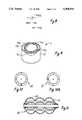
- FIG. 4is a perspective view of a single pump of the portable infusion apparatus
- FIG. 5is an exploded isometric view of the components of a single pump of the portable infusion apparatus
- FIG. 6Ais a cross sectional view of a single pump of the portable infusion apparatus as seen along line 6--6 in FIG. 5 with an elastomeric membrane of the pump collapsed;
- FIG. 6Bis a cross sectional view of a single pump of the portable infusion apparatus as seen in FIG. 6A with the elastomeric membrane of the pump expanded to establish a pressurized fluid chamber;
- FIG. 7Ais a modeled and empirically obtained Pressure versus Volume graph for the separate pumps of the infusion apparatus
- FIG. 7Bis a Pressure v. Volume Delivered graph showing the discharge of fluids in a SASH process in a timed sequence
- FIG. 8is schematic diagram of a check valve component for the infusion apparatus
- FIG. 9is a schematic view of an alternate embodiment portable infusion apparatus
- FIGS. 10 and 10Aare plan views of another alternate embodiment portable infusion apparatus for a SAS sequence.
- FIG. 11is a schematic view of yet another alternate embodiment portable infusion apparatus having a generally cylindrical construction.
- an infusion apparatus for infusing medical solutions in accordance with the inventionis shown and generally designated as 10.
- the infusion apparatus 10may be worn by a patient 12 during ambulation and can be attached to the patient 12 by any well known means, such as a belt 14.
- FIG. 1shows that the infusion apparatus 10 can be connected in fluid communication with the patient 12 for the infusion of fluids into the patient 12 through an IV line 16.
- the IV line 16can include an in-line air filter 18 of a type well known in the pertinent art which will prevent the infusion of air to the patient 12.
- an on-off valve 20can be operatively associated with the IV line 16 to initiate or terminate the flow of fluid from the infusion apparatus 10 through the IV line 16.
- the infusion apparatus 10includes four fluid pumps 22a-d mounted within a single carrier housing 24.
- the infusion apparatus 10 shownis adapted to perform a SASH process. Alternatively a lesser or greater number of fluid pumps 22a-d may be assembled within the carrier housing 24.
- the fluid pumps 22a-dare coupled in flow communication to the IV line 16. Additionally, each pump 22a-d is coupled to a check valve 25a-d.
- the check valves 25a-bare located between the IV line 16 and the fluid pumps 22a-d to regulate a sequence of fluid flow from the fluid pumps 22a-d.
- Each fluid pump 22a-dis adapted to deliver fluid at a substantially constant pressure until the pump 22a-d is substantially completely discharged.
- Delivery pressure bands, P 1 through P 4 , of the pumps 22a-dare selected such that P 1 band, corresponding to pump 22a is greater than P 2 band corresponding to pump 22b. Likewise P 2 band is greater than P 3 band corresponding to pump 22c band and P 3 band is greater than P 4 band corresponding to pump 22d. (P 1 band>P 2 band>P 3 band>P 4 band).
- P 1 , P 2 , P 3 and P 4refer to a delivery pressure band.
- P 1 , P 2 , P 3 and P 4are not discreet values but bands of pressure which includes the difference in start to finish discharge and the manufacturing tolerances of the fluid pump 22a-d.
- the check valves 25a-dare each constructed to open at a preselected low differential pressure ⁇ P sensed between the downstream pressure in the IV line 16 and an upstream pressure determined by the pump delivery pressure of a fluid pump 22a-d.
- the check valves 25a-dcan thus be constructed and arranged to allow fluid flow sequentially from pump 22a at pressure P 1 , pump 22b at Pressure P 2 , pump 22c at pressure P 3 , and pump 22d at pressure P 4 .
- the infusion apparatus 10is thus constructed to operate in a SASH process that includes the steps of:
- a suitable fluid pump 22a-d for pumping or discharging fluid solutions at a substantially constant pressureis shown in FIGS. 4, 5, 6A and 6B.
- each of the fluid pumps 22a-dwill be of the same construction but the pumps will be sized differently.
- each pump 22a-dmay be sized to contain a predetermined volume or dosage of solution which may be different.
- the volumetric capacity of a pump 22a-dmay be in the range of 20-250 ml for an antibiotic and 3-5 ml for saline depending on a required dosage. It is anticipated that the pump will be charged with a solution at the pharmacy although it is contemplated that a patient may charge some solutions.
- Each pump 22a-dincludes a housing 27a-d.
- An elastomeric membrane 26a-dis clamped between rings 40a-d and 44a-d and is then attached to the housing 27a-d and to a shell (not shown), or to the carrier housing 34.
- FIG. 4also shows that the housing 27a-d is formed with an inlet port 28a-d and an outlet port 30a-d.
- Each outlet port 30a-d of the pumps 22a-dis coupled to an outlet conduit 31a-d which in turn is coupled to the IV line 16.
- Each check valve 25a-dis located in an outlet conduit 31a-d situated between the outlet port 30a-d of a pump 22a-d and the IV line 16.
- the individual components of a pump 22a-dare best seen in FIG. 5.
- the various components of a pump 22a-dare shown in an exploded isometric and are arranged generally in the order in which they are to be assembled.
- the housing 27a-dis made of a hard plastic, such as polycarbonate, and is of a material which is chemically compatible with the fluid to be infused into the user 12.
- a contour surface 32a-d of housing 27a-dcan have any topology which will stretch the membrane 26a-d into its nonlinear region of elasticity when these components are assembled.
- the contour surface 32a-d of housing 27a-dwill follow and conform to the natural topology of the inflated membrane 26a-d as it transitions from linear to non-linear.
- contour surface 32a-dis substantially hemispherical.
- the periphery 34a-d of housing 27a-dis folded outwardly from the contour surface 32a-d in order to facilitate the connection of the membrane 26a-d onto the housing 27a-d.
- the housing 27a-dcan be manufactured using any well known manufacturing procedures, such as injection molding.
- a thin wall tube which forms valve sleeve 36a-d, and a valve insert 38a-dare shown in FIG. 3 in their positions for insertion into the lumen of inlet port 28a-d.
- the sleeve 36a-d and valve insert 38a-destablish a one-way valve for the housing 27a-d which permits the flow of fluid in only one direction through the inlet port 28a-d.
- each fluid pump 22a-dwill be filled with fluid through the inlet port 28a-d of each chamber but that fluid not be able to leave the fluid pump 22a-d through the inlet port 28a-d.
- a fluidmay be loaded into an inlet port 28a-d under pressure utilizing a medical syringe (not shown). Additionally, it is important that during filling of the separate fluid pumps the sequence of filling be accomplished from the highest to the lowest pressures.
- Each pump 22a-dalso includes an upper top ring 40a-d which is engageable with a rib 42a-d that is located on the circumference of membrane 26a-d.
- Upper ring 40a-dis also engageable with a lower bottom ring 44a-d to effectively grip and hold the rib 42a-d of membrane 26a-d between the rings 40a-d and 44a-d.
- These rings 40a-d and 44a-dcan be of any suitable rigid material such as polycarbonate which, when the rings 40a-d and 44a-d are joined together to support the flexible membrane 26a-d, will provide a firm foundation for the membrane 26a-d.
- the membrane 26a-dis substantially a circular sheet when in its unstretched condition. Further, this sheet is formed with a raised rib 42a-d which, as mentioned above, can be gripped between the rings 40a-d and 44a-d.
- the membrane 26a-dis preferably made of a natural rubber or isoprene having a high elastic memory. Regardless of the particular material used for membrane 26a-d, however, it is important that the membrane 26a-d be chemically compatible with the fluid medicament which is to be infused to the user 12 from each pump 22a-d.
- the membrane 26a-dcan be appropriately coated so that the particular surface of membrane 26a-d which is to be placed in contact with the contour surface 32a-d of housing 27a-d will not chemically interact with the fluid medicament in the pump 22a-d.
- a medicament compatible membranecan be held with the membrane 26a-d between the rings 40a-d and 44a-d. With this combination, the medicament compatible membrane is positioned between the membrane 26a-d and the contour surface 32a-d of housing 27a-d when these components are assembled.
- the portion of membrane 26a-d which is circumscribed by the rib 42a-dis preferably of uniform thickness. It is recognized, however, that thickness may be varied across the membrane 26a-d as long as the resultant topology creates a nonlinear elastomeric behavior for the membrane 26a- d. In addition, the thickness of the membranes 26a-d will in part be different for each pump 22a-d for achieving a different operating pressure for each pump 22a-d.
- each pump 22a-dthe upper top ring 40a-d is joined to the lower bottom ring 44a-d to grip and hold rib 42a-d of membrane 26a-d therebetween.
- the rings 40a-d and 44a-dcan be joined together by any of several means, such as ultrasonic welding or solvent bonding.
- the periphery 34a-d of housing 27a-dis joined to upper top ring 40a-d.
- the contour surface 32a-d of housing 27a-dstretches membrane 26a-d substantially as shown.
- both membrane 26a-d and contour surface 32a-dare such that this stretching takes the membrane 26a-d into its nonlinear region of elasticity.
- the joining of housing 27a-d to upper top ring 40a-dalso establishes a potential chamber or reservoir 50a-d between the membrane 25a-d and contour surface 32a-d.
- any air in the systemwill first be vented to the outlet port 30a-d along the indentation 52a-d which is formed into contour surface 32a-d. This, of course, always happens when the air pressure is less than the pressure necessary to distend the membrane 26a-d. Then, with outlet port 30a-d blocked to prevent the flow of liquid medicament from chamber 50a-d, the elastomeric membrane 26a-d will begin to expand as additional liquid medicament is introduced into the potential chamber 50.
- a fluidmust be introduced under a pressure sufficient to overcome the potential energy of the initially stretched membrane 26a-d and form the chamber 50 a-d. This total amount of energy minus what has been lost through heat loss and elastomeric hysteresis is thus available for displacing fluid from the chamber 50a-d at a substantially constant delivery pressure. Further, because of the initial non-linear stretching of the membrane 26a-d, even after complete discharge of a fluid, a residual force is maintained by the membrane 26a-d acting upon the contour surface 32a-d.
- each pump 22a-dmust be sized to deliver a predetermined volume of fluid solution over a substantially constant predetermined delivery pressure.
- a size of the pump 22a-dmay thus be adjusted to achieve a predetermined volume.
- a thickness of the elastomeric membrane 26a-d as well as the materialmay be selected as required.
- the delivery pressure of a pump 22a-dwill vary with the thickness of the elastomeric membrane 26a-d. Likewise the delivery pressure will vary with the modulus of elasticity of the material selected for the elastomeric membrane 26a-d.
- FIGS. 7A and 7Billustrate representative volume versus pressure characteristics of the four fluid pumps 22a-d. Curves C a-d of FIG. 7A illustrate the volume versus pressure characteristics of pumps 22a-d respectively.
- each pump 22a-dis constructed to deliver fluid over a relatively constant pressure band.
- pump 22aoperates at the highest pressure band followed by pump 22b, 22c and 22d respectively.
- These operating pressurescorrespond to the operating pressures or pressure bands P 1 >P 2 >P 3 >P 4 shown in FIG. 3.
- An illustrative range of pressuresmay be in the range of 1-20 psig.
- FIG. 7Billustrates a volume delivered by the separate chambers over a time sequence.
- check valves 25a-d for each pump 22a-dmust be configured to crack with a relatively small pressure differential ⁇ P between the respective operating pressures P 1 -P 4 for the pumps 22a-d.
- Such check valves 25a-dare commercially available and in general function as shown in the schematic illustration of FIG. 8. Additionally, the check valve 25a downstream of pump 22a may be eliminated if desired.
- FIG. 2 with four separate fluid pumps 22a-dmay also be varied, as long as four separate reservoirs or chambers each at a different pressure are provided.
- a single pump having a single elastomeric membrane that covers a plurality of juxtaposed chambersmay be provided.
- the thickness of the elastomeric membranemay be varied to provide a pressure differential between the separate chambers.
- FIG. 9illustrates such an alternative embodiment infusion apparatus.
- Alternate embodiment infusion apparatus 51includes a housing 53 having a plurality of contour surfaces 54a-d formed thereon.
- a single concentric elastomeric membrane 56is mounted in operative alignment with the contour surfaces 54a-d substantially as described for elastomeric membrane 26a-d.
- Concentric elastomeric membrane 56is formed however, with a varying thickness for providing chambers corresponding to contour surfaces 54a-d. The pumping or delivery pressure from each chamber can thus be varied as required.
- a single infusion apparatus 60 for a SASH processmay include four separate chambers S,A,S,H, concentrically arranged and divided.
- FIG. 10Aillustrates a single infusion apparatus 62 having three separate and concentrically arranged chambers (S,A,S). In either case the largest chamber (A) is in the center.
- FIG. 11illustrates yet another infusion apparatus 64 formed with a shell 68 and separate chambers formed by a single elastomeric membrane 66.
- the shell 66may be sized to contain a fixed volume for each separate chamber.
- the inventionprovides a method and apparatus for infusing a plurality of medical solutions in a controlled sequence.
- the apparatus of the inventionis simple in construction and may operate automatically in a SASH process.
- the method and apparatus of the inventionis suitable for use by a mobile or ambulatory patient.
Landscapes
- Health & Medical Sciences (AREA)
- Vascular Medicine (AREA)
- Engineering & Computer Science (AREA)
- Anesthesiology (AREA)
- Biomedical Technology (AREA)
- Heart & Thoracic Surgery (AREA)
- Hematology (AREA)
- Life Sciences & Earth Sciences (AREA)
- Animal Behavior & Ethology (AREA)
- General Health & Medical Sciences (AREA)
- Public Health (AREA)
- Veterinary Medicine (AREA)
- Infusion, Injection, And Reservoir Apparatuses (AREA)
Abstract
Description
Claims (13)
Priority Applications (5)
| Application Number | Priority Date | Filing Date | Title |
|---|---|---|---|
| US07/790,367US5368570A (en) | 1991-11-12 | 1991-11-12 | Apparatus for infusing medical solutions |
| CA002068563ACA2068563A1 (en) | 1991-11-12 | 1992-05-13 | Method and apparatus for infusing medical solutions |
| EP92305358AEP0542401A1 (en) | 1991-11-12 | 1992-06-11 | Method and apparatus for infusing medical solutions |
| JP4178754AJPH05208049A (en) | 1991-11-12 | 1992-07-07 | Method and apparatus for injecting medi- cal solution |
| AU23569/92AAU2356992A (en) | 1991-11-12 | 1992-09-14 | Method and apparatus for infusing medical solutions |
Applications Claiming Priority (1)
| Application Number | Priority Date | Filing Date | Title |
|---|---|---|---|
| US07/790,367US5368570A (en) | 1991-11-12 | 1991-11-12 | Apparatus for infusing medical solutions |
Publications (1)
| Publication Number | Publication Date |
|---|---|
| US5368570Atrue US5368570A (en) | 1994-11-29 |
Family
ID=25150481
Family Applications (1)
| Application Number | Title | Priority Date | Filing Date |
|---|---|---|---|
| US07/790,367Expired - LifetimeUS5368570A (en) | 1991-11-12 | 1991-11-12 | Apparatus for infusing medical solutions |
Country Status (5)
| Country | Link |
|---|---|
| US (1) | US5368570A (en) |
| EP (1) | EP0542401A1 (en) |
| JP (1) | JPH05208049A (en) |
| AU (1) | AU2356992A (en) |
| CA (1) | CA2068563A1 (en) |
Cited By (50)
| Publication number | Priority date | Publication date | Assignee | Title |
|---|---|---|---|---|
| US5496303A (en)* | 1991-09-18 | 1996-03-05 | Pierre Antonetti | Transfusion and perfusion device for drip and/or emergency intervention |
| US5656032A (en)* | 1989-06-16 | 1997-08-12 | Science Incorporated | Fluid delivery apparatus and method of making same |
| US5830187A (en)* | 1995-12-22 | 1998-11-03 | Science Incorporated | Fluid delivery device with conformable ullage and fill assembly |
| WO1999010040A1 (en)* | 1997-08-27 | 1999-03-04 | Science Incorporated | Fluid delivery device with temperature controlled energy source |
| US6068613A (en)* | 1989-06-16 | 2000-05-30 | Kriesel; Marshall S. | Fluid delivery device |
| US6074366A (en)* | 1998-01-16 | 2000-06-13 | Tandem Medical Inc. | Medication delivery apparatus |
| US6193704B1 (en) | 1999-06-10 | 2001-02-27 | Thomas F. Winters | Site-specific postoperative pain relief system, fit and method |
| US6200293B1 (en)* | 1997-08-27 | 2001-03-13 | Science Incorporated | Fluid delivery device with temperature controlled energy source |
| US6391001B1 (en)* | 2000-09-21 | 2002-05-21 | Jolie Graham | Intravenous line flushing device |
| WO2002026282A3 (en)* | 2000-06-28 | 2002-07-25 | Science Inc | Fluid delivery device with light activated energy source |
| US6428518B1 (en) | 1999-11-05 | 2002-08-06 | Tandem Medical | Medication delivery container |
| US6485462B1 (en)* | 1997-08-27 | 2002-11-26 | Science Incorporated | Fluid delivery device with heat activated energy source |
| US20030105428A1 (en)* | 2001-12-05 | 2003-06-05 | John Hogan | Electronically controlled fluid delivery device |
| WO2003097156A1 (en)* | 2002-05-16 | 2003-11-27 | Scott Laborotories Inc. | Kits of medical supplies for sedation and analgesia |
| US6726655B1 (en) | 1999-11-05 | 2004-04-27 | Tandem Medical | Medication delivery system |
| US20060287633A1 (en)* | 2005-06-15 | 2006-12-21 | Jen-Hsien Yo | Portable device for transfusing medical fluid |
| WO2006058280A3 (en)* | 2004-11-24 | 2007-04-05 | Medrad Inc | Devices, systems and methods for fluid delivery |
| US20070166181A1 (en)* | 2002-03-14 | 2007-07-19 | Billy Nilson | Ambulatory infusion membrane pump |
| US20080097317A1 (en)* | 2006-08-25 | 2008-04-24 | Jeffery Alholm | Infusion pump |
| US20080215029A1 (en)* | 1993-01-22 | 2008-09-04 | I-Flow Corporation | Platen pump |
| US20100100038A1 (en)* | 2008-10-15 | 2010-04-22 | Symbios Medical Products, Llc | Electronic flow control |
| US7985216B2 (en) | 2004-03-16 | 2011-07-26 | Dali Medical Devices Ltd. | Medicinal container engagement and automatic needle device |
| US8376998B2 (en) | 2003-09-17 | 2013-02-19 | Elcam Medical Agricultural Cooperative Association Ltd. | Automatic injection device |
| US9008759B2 (en) | 2007-07-17 | 2015-04-14 | Bayer Medical Care Inc. | Devices and systems for determination of parameters for a procedure, for estimation of cardiopulmonary function and for fluid delivery |
| CN105056338A (en)* | 2015-08-24 | 2015-11-18 | 吴江富凯医用卫生用品有限公司 | Portable infusion frame |
| US9302044B2 (en) | 2006-12-29 | 2016-04-05 | Bayer Healthcare Llc | Patient-based parameter generation systems for medical injection procedures |
| US9421330B2 (en) | 2008-11-03 | 2016-08-23 | Bayer Healthcare Llc | Mitigation of contrast-induced nephropathy |
| US9616166B2 (en) | 2004-11-16 | 2017-04-11 | Bayer Healthcare Llc | Systems and methods of determining injection protocols for diagnostic imaging procedures |
| US9849233B1 (en)* | 2017-05-10 | 2017-12-26 | Novus Medical Products, Inc. | Disposable infusion pump system for ambulatory patients |
| US9949704B2 (en) | 2012-05-14 | 2018-04-24 | Bayer Healthcare Llc | Systems and methods for determination of pharmaceutical fluid injection protocols based on x-ray tube voltage |
| US9959389B2 (en) | 2010-06-24 | 2018-05-01 | Bayer Healthcare Llc | Modeling of pharmaceutical propagation and parameter generation for injection protocols |
| US20200261645A1 (en)* | 2006-02-09 | 2020-08-20 | Deka Products Limited Partnership | Patch-sized fluid delivery systems and methods |
| US10898638B2 (en) | 2016-03-03 | 2021-01-26 | Bayer Healthcare Llc | System and method for improved fluid delivery in multi-fluid injector systems |
| WO2021164986A1 (en)* | 2020-02-20 | 2021-08-26 | B. Braun Melsungen Ag | Elastomeric membrane for a medical elastomer pump, and medical elastomer pump having such elastomeric membrane |
| US11141535B2 (en) | 2017-08-31 | 2021-10-12 | Bayer Healthcare Llc | Fluid path impedance assessment for improving fluid delivery performance |
| US11278853B2 (en) | 2013-03-13 | 2022-03-22 | Bayer Healthcare Llc | Method for controlling fluid accuracy and backflow compensation |
| US11364339B2 (en) | 2019-07-11 | 2022-06-21 | Aamir Zain Jamal | Infusion unit |
| US11478581B2 (en) | 2017-08-31 | 2022-10-25 | Bayer Healthcare Llc | Fluid injector system volume compensation system and method |
| US11598664B2 (en) | 2017-08-31 | 2023-03-07 | Bayer Healthcare Llc | Injector pressure calibration system and method |
| US11660389B2 (en)* | 2018-07-17 | 2023-05-30 | Insulet Corporation | Semi-rigid and flexible elements for wearable drug delivery device reservoir |
| US11779702B2 (en) | 2017-08-31 | 2023-10-10 | Bayer Healthcare Llc | Method for dynamic pressure control in a fluid injector system |
| US11786652B2 (en) | 2017-08-31 | 2023-10-17 | Bayer Healthcare Llc | System and method for drive member position and fluid injector system mechanical calibration |
| EP4140521A4 (en)* | 2020-04-20 | 2023-12-27 | SK-Electronics CO., LTD. | Pressurization-type drug injector having drug exposure preventive function |
| USD1024314S1 (en) | 2022-06-01 | 2024-04-23 | Insulet Corporation | Automated drug delivery device |
| US11980736B2 (en) | 2020-05-26 | 2024-05-14 | Carefusion 202, Inc. | Infusion pump flow rate control |
| US12090498B2 (en) | 2021-08-19 | 2024-09-17 | Insulet Corporation | Low-friction rolling plunger for a wearable drug delivery device |
| US12208239B2 (en) | 2018-08-28 | 2025-01-28 | Bayer Healthcare Llc | Fluid injector system, method of preventing fluid backflow, and computer program product |
| US12251544B2 (en) | 2018-04-19 | 2025-03-18 | Bayer Healthcare Llc | System and method for air detection in fluid injector |
| US12263326B2 (en) | 2016-11-14 | 2025-04-01 | Bayer Healthcare Llc | Methods and systems for verifying the contents of a syringe used for medical fluid delivery |
| US12427249B2 (en) | 2018-08-28 | 2025-09-30 | Bayer Healthcare Llc | Fluid injector system with improved ratio performance |
Families Citing this family (6)
| Publication number | Priority date | Publication date | Assignee | Title |
|---|---|---|---|---|
| JPH062664A (en)* | 1992-06-22 | 1994-01-11 | Nippon Soken Inc | Diaphragm type pump |
| US5478211A (en)* | 1994-03-09 | 1995-12-26 | Baxter International Inc. | Ambulatory infusion pump |
| WO1998001169A2 (en)* | 1996-07-07 | 1998-01-15 | Volker Lang | Application device with metering container, in particular for dispensing drug solutions |
| EP3351277A1 (en)* | 2002-03-26 | 2018-07-25 | Becton, Dickinson and Company | Multi-stage fluid delivery device and method |
| US8282046B2 (en)* | 2009-02-12 | 2012-10-09 | Becton, Dickinson And Company | Systems and methods for organizing and priming an IV administration set |
| US8968242B2 (en) | 2012-02-10 | 2015-03-03 | Avent, Inc. | Inflatable elastomeric pump for an infusion assembly |
Citations (58)
| Publication number | Priority date | Publication date | Assignee | Title |
|---|---|---|---|---|
| US7816A (en)* | 1850-12-03 | Improvement in vulcanizing india-rubber | ||
| US1895623A (en)* | 1930-03-10 | 1933-01-31 | William R Hewitt | Pump |
| US1907673A (en)* | 1931-06-13 | 1933-05-09 | Edward A Rockwell | Fuel pump |
| US2222869A (en)* | 1937-05-27 | 1940-11-26 | Jencick Stephen | Pump |
| US2471796A (en)* | 1945-10-01 | 1949-05-31 | George A Thiberg | Air pump for aquarium aerators |
| US2764942A (en)* | 1953-11-03 | 1956-10-02 | Guarnaschelli Vincent | Fuel pump adjusters |
| US2791186A (en)* | 1954-01-04 | 1957-05-07 | Phillips Petroleum Co | Liquid-fuel system |
| US2803195A (en)* | 1953-02-19 | 1957-08-20 | Lock John Henry | Fuel pump |
| US2930324A (en)* | 1955-10-03 | 1960-03-29 | Ohio Commw Eng Co | Magnetic pump |
| US3039399A (en)* | 1959-12-07 | 1962-06-19 | Foregger Company Inc | Pump |
| US3080825A (en)* | 1960-02-11 | 1963-03-12 | Guarnaschelli Vincent | Fuel pump adjusters |
| US3212446A (en)* | 1962-10-18 | 1965-10-19 | Robertshaw Controls Co | Fluid pump or the like and method for making the same |
| US3381582A (en)* | 1966-06-24 | 1968-05-07 | Robertshaw Controls Co | Fluidic operated multiposition actuator or the like |
| US3412906A (en)* | 1966-12-05 | 1968-11-26 | Amp Inc | Plasma infusor |
| US3416461A (en)* | 1966-09-01 | 1968-12-17 | Hills Mccanna Co | Diaphragm pump |
| US3468308A (en)* | 1966-01-17 | 1969-09-23 | Howard R Bierman | Pressure infusion device for ambulatory patients with pressure control means |
| US3469578A (en)* | 1965-10-12 | 1969-09-30 | Howard R Bierman | Infusion device for ambulatory patients with flow control means |
| US3496878A (en)* | 1967-04-07 | 1970-02-24 | Bio Medical Systems Inc | System and apparatus for transfer of human fluids |
| US3506005A (en)* | 1967-02-23 | 1970-04-14 | Arthur S Gilio | Pressure infusion device for medical use |
| US3653377A (en)* | 1970-10-01 | 1972-04-04 | Bloom Leonard | Portable power-operated douching appliance |
| US3672543A (en)* | 1971-02-11 | 1972-06-27 | Plant Ind Inc | Flowable substances dispenser |
| US3677444A (en)* | 1970-03-06 | 1972-07-18 | Estin Hans H | Micropump |
| US3698595A (en)* | 1969-12-22 | 1972-10-17 | Norman Gortz | Pressurized dispenser |
| US3738538A (en)* | 1971-02-11 | 1973-06-12 | Plant Ind Inc | Dispenser for flowable substances |
| US3791557A (en)* | 1972-01-13 | 1974-02-12 | Plant Ind Inc | Non-aerosol container with expansible bladder and expelling force providing sheath |
| US3796356A (en)* | 1972-04-12 | 1974-03-12 | Plant Ind Inc | Telescoping mandrel for expansible bladder container |
| US3876115A (en)* | 1972-04-27 | 1975-04-08 | Plant Ind Inc | Double expansible bladder container |
| US3907169A (en)* | 1970-11-03 | 1975-09-23 | Norman Gortz | Bladder type dispenser |
| US3940026A (en)* | 1973-03-26 | 1976-02-24 | Krdc | Container for pressure dispensing of fluid |
| US3947156A (en)* | 1972-03-08 | 1976-03-30 | Erich Becker | Diaphragm pump, particularly for the generation of vacuum |
| US3961725A (en)* | 1974-04-09 | 1976-06-08 | Clark Richard A | Method and apparatus for dispensing fluids under pressure |
| US3981415A (en)* | 1975-10-29 | 1976-09-21 | E. I. Du Pont De Nemours And Company | Dispenser with expansible member and contracting fabric |
| US4140117A (en)* | 1975-05-12 | 1979-02-20 | Alza Corporation | Cartridge for liquid infusion apparatus |
| US4222499A (en)* | 1979-05-07 | 1980-09-16 | Kain's Research & Development Company, Inc. | Pressurized fluid dispensing apparatus having expansible bladder held in place with compressive forces |
| US4318400A (en)* | 1980-01-18 | 1982-03-09 | Alza Corporation | Medical infusor |
| US4324350A (en)* | 1978-04-24 | 1982-04-13 | Thompson Kenneth W | Elastomeric apparatus for pressure dispensing of fluid |
| US4386929A (en)* | 1980-01-18 | 1983-06-07 | Alza Corporation | Elastomeric bladder assembly |
| US4411603A (en)* | 1981-06-24 | 1983-10-25 | Cordis Dow Corp. | Diaphragm type blood pump for medical use |
| US4419096A (en)* | 1982-02-22 | 1983-12-06 | Alza Corporation | Elastomeric bladder assembly |
| US4446991A (en)* | 1978-04-24 | 1984-05-08 | Thompson Kenneth W | Self-contained fluid dispenser |
| US4458830A (en)* | 1981-05-18 | 1984-07-10 | Werding Winfried J | Appliance for discharging a non-compressible liquid, creamy or pasty product under pressure |
| US4491247A (en)* | 1981-07-21 | 1985-01-01 | Nitchman Harold L | System, apparatus, and method of dispensing a liquid from a semi-bulk disposable container |
| US4541788A (en)* | 1983-04-19 | 1985-09-17 | Toyota Jidosha Kabushiki Kaisha | Diaphragm fluid pump |
| US4573883A (en)* | 1985-03-01 | 1986-03-04 | Baylor College Of Medicine | Disposable blood pump |
| US4702397A (en)* | 1984-09-18 | 1987-10-27 | Infusion Systems Corporation | Pressurized fluid dispenser |
| US4734092A (en)* | 1987-02-18 | 1988-03-29 | Ivac Corporation | Ambulatory drug delivery device |
| US4734008A (en)* | 1986-06-20 | 1988-03-29 | General Motors Corporation | Pump impeller |
| US4772263A (en)* | 1986-02-03 | 1988-09-20 | Regents Of The University Of Minnesota | Spring driven infusion pump |
| US4925444A (en)* | 1987-08-07 | 1990-05-15 | Baxter Travenol Laboratories, Inc. | Closed multi-fluid delivery system and method |
| US4953753A (en)* | 1988-06-10 | 1990-09-04 | The Norman Company | Fluid dispensing apparatus with prestressed bladder |
| US4968301A (en)* | 1989-02-02 | 1990-11-06 | Imed Corporation | Disposable infusion device |
| EP0399712A1 (en)* | 1989-05-25 | 1990-11-28 | Schneider (Usa) Inc. | Intravascular drug delivery dilation catheter |
| US5013303A (en)* | 1988-11-03 | 1991-05-07 | Yehuda Tamari | Constant pressure infusion device |
| US5019047A (en)* | 1989-06-16 | 1991-05-28 | Science Incorporated | Fluid delivery apparatus |
| WO1992011881A1 (en)* | 1990-12-27 | 1992-07-23 | Block Medical, Inc. | Closed system for iv site flush |
| US5167631A (en)* | 1991-09-17 | 1992-12-01 | Imed Corporation | Portable infusion device |
| US5188603A (en)* | 1991-01-03 | 1993-02-23 | Vaillancourt Vincent L | Fluid infusion delivery system |
| US5298025A (en)* | 1991-07-08 | 1994-03-29 | Baxter International Inc. | Sequential flow rate infusion rate |
Family Cites Families (2)
| Publication number | Priority date | Publication date | Assignee | Title |
|---|---|---|---|---|
| DE2430673A1 (en)* | 1974-06-26 | 1976-01-15 | Essig Georg | Medical continuous infusion system - has multi fluid-container system with automatic change-over, level sensor, cut-off valve and alarm |
| JPS56500240A (en)* | 1979-02-28 | 1981-03-05 |
- 1991
- 1991-11-12USUS07/790,367patent/US5368570A/ennot_activeExpired - Lifetime
- 1992
- 1992-05-13CACA002068563Apatent/CA2068563A1/ennot_activeAbandoned
- 1992-06-11EPEP92305358Apatent/EP0542401A1/ennot_activeWithdrawn
- 1992-07-07JPJP4178754Apatent/JPH05208049A/enactivePending
- 1992-09-14AUAU23569/92Apatent/AU2356992A/ennot_activeAbandoned
Patent Citations (58)
| Publication number | Priority date | Publication date | Assignee | Title |
|---|---|---|---|---|
| US7816A (en)* | 1850-12-03 | Improvement in vulcanizing india-rubber | ||
| US1895623A (en)* | 1930-03-10 | 1933-01-31 | William R Hewitt | Pump |
| US1907673A (en)* | 1931-06-13 | 1933-05-09 | Edward A Rockwell | Fuel pump |
| US2222869A (en)* | 1937-05-27 | 1940-11-26 | Jencick Stephen | Pump |
| US2471796A (en)* | 1945-10-01 | 1949-05-31 | George A Thiberg | Air pump for aquarium aerators |
| US2803195A (en)* | 1953-02-19 | 1957-08-20 | Lock John Henry | Fuel pump |
| US2764942A (en)* | 1953-11-03 | 1956-10-02 | Guarnaschelli Vincent | Fuel pump adjusters |
| US2791186A (en)* | 1954-01-04 | 1957-05-07 | Phillips Petroleum Co | Liquid-fuel system |
| US2930324A (en)* | 1955-10-03 | 1960-03-29 | Ohio Commw Eng Co | Magnetic pump |
| US3039399A (en)* | 1959-12-07 | 1962-06-19 | Foregger Company Inc | Pump |
| US3080825A (en)* | 1960-02-11 | 1963-03-12 | Guarnaschelli Vincent | Fuel pump adjusters |
| US3212446A (en)* | 1962-10-18 | 1965-10-19 | Robertshaw Controls Co | Fluid pump or the like and method for making the same |
| US3469578A (en)* | 1965-10-12 | 1969-09-30 | Howard R Bierman | Infusion device for ambulatory patients with flow control means |
| US3468308A (en)* | 1966-01-17 | 1969-09-23 | Howard R Bierman | Pressure infusion device for ambulatory patients with pressure control means |
| US3381582A (en)* | 1966-06-24 | 1968-05-07 | Robertshaw Controls Co | Fluidic operated multiposition actuator or the like |
| US3416461A (en)* | 1966-09-01 | 1968-12-17 | Hills Mccanna Co | Diaphragm pump |
| US3412906A (en)* | 1966-12-05 | 1968-11-26 | Amp Inc | Plasma infusor |
| US3506005A (en)* | 1967-02-23 | 1970-04-14 | Arthur S Gilio | Pressure infusion device for medical use |
| US3496878A (en)* | 1967-04-07 | 1970-02-24 | Bio Medical Systems Inc | System and apparatus for transfer of human fluids |
| US3698595A (en)* | 1969-12-22 | 1972-10-17 | Norman Gortz | Pressurized dispenser |
| US3677444A (en)* | 1970-03-06 | 1972-07-18 | Estin Hans H | Micropump |
| US3653377A (en)* | 1970-10-01 | 1972-04-04 | Bloom Leonard | Portable power-operated douching appliance |
| US3907169A (en)* | 1970-11-03 | 1975-09-23 | Norman Gortz | Bladder type dispenser |
| US3672543A (en)* | 1971-02-11 | 1972-06-27 | Plant Ind Inc | Flowable substances dispenser |
| US3738538A (en)* | 1971-02-11 | 1973-06-12 | Plant Ind Inc | Dispenser for flowable substances |
| US3791557A (en)* | 1972-01-13 | 1974-02-12 | Plant Ind Inc | Non-aerosol container with expansible bladder and expelling force providing sheath |
| US3947156A (en)* | 1972-03-08 | 1976-03-30 | Erich Becker | Diaphragm pump, particularly for the generation of vacuum |
| US3796356A (en)* | 1972-04-12 | 1974-03-12 | Plant Ind Inc | Telescoping mandrel for expansible bladder container |
| US3876115A (en)* | 1972-04-27 | 1975-04-08 | Plant Ind Inc | Double expansible bladder container |
| US3940026A (en)* | 1973-03-26 | 1976-02-24 | Krdc | Container for pressure dispensing of fluid |
| US3961725A (en)* | 1974-04-09 | 1976-06-08 | Clark Richard A | Method and apparatus for dispensing fluids under pressure |
| US4140117A (en)* | 1975-05-12 | 1979-02-20 | Alza Corporation | Cartridge for liquid infusion apparatus |
| US3981415A (en)* | 1975-10-29 | 1976-09-21 | E. I. Du Pont De Nemours And Company | Dispenser with expansible member and contracting fabric |
| US4324350A (en)* | 1978-04-24 | 1982-04-13 | Thompson Kenneth W | Elastomeric apparatus for pressure dispensing of fluid |
| US4446991A (en)* | 1978-04-24 | 1984-05-08 | Thompson Kenneth W | Self-contained fluid dispenser |
| US4222499A (en)* | 1979-05-07 | 1980-09-16 | Kain's Research & Development Company, Inc. | Pressurized fluid dispensing apparatus having expansible bladder held in place with compressive forces |
| US4386929A (en)* | 1980-01-18 | 1983-06-07 | Alza Corporation | Elastomeric bladder assembly |
| US4318400A (en)* | 1980-01-18 | 1982-03-09 | Alza Corporation | Medical infusor |
| US4458830A (en)* | 1981-05-18 | 1984-07-10 | Werding Winfried J | Appliance for discharging a non-compressible liquid, creamy or pasty product under pressure |
| US4411603A (en)* | 1981-06-24 | 1983-10-25 | Cordis Dow Corp. | Diaphragm type blood pump for medical use |
| US4491247A (en)* | 1981-07-21 | 1985-01-01 | Nitchman Harold L | System, apparatus, and method of dispensing a liquid from a semi-bulk disposable container |
| US4419096A (en)* | 1982-02-22 | 1983-12-06 | Alza Corporation | Elastomeric bladder assembly |
| US4541788A (en)* | 1983-04-19 | 1985-09-17 | Toyota Jidosha Kabushiki Kaisha | Diaphragm fluid pump |
| US4702397A (en)* | 1984-09-18 | 1987-10-27 | Infusion Systems Corporation | Pressurized fluid dispenser |
| US4573883A (en)* | 1985-03-01 | 1986-03-04 | Baylor College Of Medicine | Disposable blood pump |
| US4772263A (en)* | 1986-02-03 | 1988-09-20 | Regents Of The University Of Minnesota | Spring driven infusion pump |
| US4734008A (en)* | 1986-06-20 | 1988-03-29 | General Motors Corporation | Pump impeller |
| US4734092A (en)* | 1987-02-18 | 1988-03-29 | Ivac Corporation | Ambulatory drug delivery device |
| US4925444A (en)* | 1987-08-07 | 1990-05-15 | Baxter Travenol Laboratories, Inc. | Closed multi-fluid delivery system and method |
| US4953753A (en)* | 1988-06-10 | 1990-09-04 | The Norman Company | Fluid dispensing apparatus with prestressed bladder |
| US5013303A (en)* | 1988-11-03 | 1991-05-07 | Yehuda Tamari | Constant pressure infusion device |
| US4968301A (en)* | 1989-02-02 | 1990-11-06 | Imed Corporation | Disposable infusion device |
| EP0399712A1 (en)* | 1989-05-25 | 1990-11-28 | Schneider (Usa) Inc. | Intravascular drug delivery dilation catheter |
| US5019047A (en)* | 1989-06-16 | 1991-05-28 | Science Incorporated | Fluid delivery apparatus |
| WO1992011881A1 (en)* | 1990-12-27 | 1992-07-23 | Block Medical, Inc. | Closed system for iv site flush |
| US5188603A (en)* | 1991-01-03 | 1993-02-23 | Vaillancourt Vincent L | Fluid infusion delivery system |
| US5298025A (en)* | 1991-07-08 | 1994-03-29 | Baxter International Inc. | Sequential flow rate infusion rate |
| US5167631A (en)* | 1991-09-17 | 1992-12-01 | Imed Corporation | Portable infusion device |
Non-Patent Citations (4)
| Title |
|---|
| The Aminoclycoside Delivery System, Infusions Systems Corporation.* |
| The Homepump Family of Disposable Elastomeric Infusion Systems, McGaw, Inc.* |
| Travenol Infusor Chemotherapy, Travenol.* |
| Vs. Pharmacy Control, Baxter.* |
Cited By (71)
| Publication number | Priority date | Publication date | Assignee | Title |
|---|---|---|---|---|
| US5656032A (en)* | 1989-06-16 | 1997-08-12 | Science Incorporated | Fluid delivery apparatus and method of making same |
| US6068613A (en)* | 1989-06-16 | 2000-05-30 | Kriesel; Marshall S. | Fluid delivery device |
| US5496303A (en)* | 1991-09-18 | 1996-03-05 | Pierre Antonetti | Transfusion and perfusion device for drip and/or emergency intervention |
| US20080215029A1 (en)* | 1993-01-22 | 2008-09-04 | I-Flow Corporation | Platen pump |
| US5830187A (en)* | 1995-12-22 | 1998-11-03 | Science Incorporated | Fluid delivery device with conformable ullage and fill assembly |
| US6045533A (en)* | 1995-12-22 | 2000-04-04 | Science Incorporated | Fluid delivery device with conformable ullage and fill assembly |
| WO1999010040A1 (en)* | 1997-08-27 | 1999-03-04 | Science Incorporated | Fluid delivery device with temperature controlled energy source |
| US5961492A (en)* | 1997-08-27 | 1999-10-05 | Science Incorporated | Fluid delivery device with temperature controlled energy source |
| US6485462B1 (en)* | 1997-08-27 | 2002-11-26 | Science Incorporated | Fluid delivery device with heat activated energy source |
| US6527744B1 (en)* | 1997-08-27 | 2003-03-04 | Science Incorporated | Fluid delivery device with light activated energy source |
| US6537250B1 (en)* | 1997-08-27 | 2003-03-25 | Science, Incorporated | Fluid delivery device with electrically activated energy source |
| US6200293B1 (en)* | 1997-08-27 | 2001-03-13 | Science Incorporated | Fluid delivery device with temperature controlled energy source |
| US6146360A (en)* | 1998-01-16 | 2000-11-14 | Tandem Medical, Inc. | Medication delivery apparatus |
| US6416496B1 (en) | 1998-01-16 | 2002-07-09 | Tandem Medical, Inc. | Medication delivery apparatus |
| US6074366A (en)* | 1998-01-16 | 2000-06-13 | Tandem Medical Inc. | Medication delivery apparatus |
| US6193704B1 (en) | 1999-06-10 | 2001-02-27 | Thomas F. Winters | Site-specific postoperative pain relief system, fit and method |
| US6726655B1 (en) | 1999-11-05 | 2004-04-27 | Tandem Medical | Medication delivery system |
| US6428518B1 (en) | 1999-11-05 | 2002-08-06 | Tandem Medical | Medication delivery container |
| WO2002026282A3 (en)* | 2000-06-28 | 2002-07-25 | Science Inc | Fluid delivery device with light activated energy source |
| US6391001B1 (en)* | 2000-09-21 | 2002-05-21 | Jolie Graham | Intravenous line flushing device |
| US20030105428A1 (en)* | 2001-12-05 | 2003-06-05 | John Hogan | Electronically controlled fluid delivery device |
| US20070166181A1 (en)* | 2002-03-14 | 2007-07-19 | Billy Nilson | Ambulatory infusion membrane pump |
| WO2003097156A1 (en)* | 2002-05-16 | 2003-11-27 | Scott Laborotories Inc. | Kits of medical supplies for sedation and analgesia |
| US11623051B2 (en) | 2003-09-17 | 2023-04-11 | E3D Agricultural Cooperative Association Ltd. | Automatic injection device |
| EP2650033A2 (en) | 2003-09-17 | 2013-10-16 | Elcam Medical Agricultural Cooperative Association Ltd. | Automatic injection device |
| US8376998B2 (en) | 2003-09-17 | 2013-02-19 | Elcam Medical Agricultural Cooperative Association Ltd. | Automatic injection device |
| US7985216B2 (en) | 2004-03-16 | 2011-07-26 | Dali Medical Devices Ltd. | Medicinal container engagement and automatic needle device |
| US9616166B2 (en) | 2004-11-16 | 2017-04-11 | Bayer Healthcare Llc | Systems and methods of determining injection protocols for diagnostic imaging procedures |
| WO2006058280A3 (en)* | 2004-11-24 | 2007-04-05 | Medrad Inc | Devices, systems and methods for fluid delivery |
| US7925330B2 (en) | 2004-11-24 | 2011-04-12 | Medrad, Inc. | Devices, systems and methods for determining parameters of one or more phases of an injection procedure |
| US9238099B2 (en) | 2004-11-24 | 2016-01-19 | Bayer Healthcare Llc | System and apparatus for modeling pressures generated during an injection procedure |
| US9950107B2 (en) | 2004-11-24 | 2018-04-24 | Bayer Healthcare Llc | Systems and methods for managing workflow for injection procedures |
| US10166326B2 (en) | 2004-11-24 | 2019-01-01 | Bayer Healthcare Llc | Devices, systems and methods for determining parameters of one or more phases of an injection procedure |
| US20060287633A1 (en)* | 2005-06-15 | 2006-12-21 | Jen-Hsien Yo | Portable device for transfusing medical fluid |
| US12233235B2 (en)* | 2006-02-09 | 2025-02-25 | Deka Products Limited Partnership | Patch-sized fluid delivery systems and methods |
| US20200261645A1 (en)* | 2006-02-09 | 2020-08-20 | Deka Products Limited Partnership | Patch-sized fluid delivery systems and methods |
| WO2008024817A3 (en)* | 2006-08-25 | 2008-10-02 | Symbios Medical Products Llc | Infusion pump |
| US20080097317A1 (en)* | 2006-08-25 | 2008-04-24 | Jeffery Alholm | Infusion pump |
| US9302044B2 (en) | 2006-12-29 | 2016-04-05 | Bayer Healthcare Llc | Patient-based parameter generation systems for medical injection procedures |
| US10463782B2 (en) | 2006-12-29 | 2019-11-05 | Bayer Healthcare Llc | Patient-based parameter generation systems for medical injection procedures |
| US9008759B2 (en) | 2007-07-17 | 2015-04-14 | Bayer Medical Care Inc. | Devices and systems for determination of parameters for a procedure, for estimation of cardiopulmonary function and for fluid delivery |
| WO2010045422A1 (en)* | 2008-10-15 | 2010-04-22 | Symbios Medical Products, Llc | Electronic flow control |
| US20100100038A1 (en)* | 2008-10-15 | 2010-04-22 | Symbios Medical Products, Llc | Electronic flow control |
| US9421330B2 (en) | 2008-11-03 | 2016-08-23 | Bayer Healthcare Llc | Mitigation of contrast-induced nephropathy |
| US9959389B2 (en) | 2010-06-24 | 2018-05-01 | Bayer Healthcare Llc | Modeling of pharmaceutical propagation and parameter generation for injection protocols |
| US9949704B2 (en) | 2012-05-14 | 2018-04-24 | Bayer Healthcare Llc | Systems and methods for determination of pharmaceutical fluid injection protocols based on x-ray tube voltage |
| US11191501B2 (en) | 2012-05-14 | 2021-12-07 | Bayer Healthcare Llc | Systems and methods for determination of pharmaceutical fluid injection protocols based on x-ray tube voltage |
| US11278853B2 (en) | 2013-03-13 | 2022-03-22 | Bayer Healthcare Llc | Method for controlling fluid accuracy and backflow compensation |
| CN105056338A (en)* | 2015-08-24 | 2015-11-18 | 吴江富凯医用卫生用品有限公司 | Portable infusion frame |
| US10898638B2 (en) | 2016-03-03 | 2021-01-26 | Bayer Healthcare Llc | System and method for improved fluid delivery in multi-fluid injector systems |
| US11672902B2 (en) | 2016-03-03 | 2023-06-13 | Bayer Healthcare Llc | System and method for improved fluid delivery in multi-fluid injector systems |
| US12263326B2 (en) | 2016-11-14 | 2025-04-01 | Bayer Healthcare Llc | Methods and systems for verifying the contents of a syringe used for medical fluid delivery |
| US9849233B1 (en)* | 2017-05-10 | 2017-12-26 | Novus Medical Products, Inc. | Disposable infusion pump system for ambulatory patients |
| US11141535B2 (en) | 2017-08-31 | 2021-10-12 | Bayer Healthcare Llc | Fluid path impedance assessment for improving fluid delivery performance |
| US12214155B2 (en) | 2017-08-31 | 2025-02-04 | Bayer Healthcare Llc | Fluid injector system volume compensation system and method |
| US11478581B2 (en) | 2017-08-31 | 2022-10-25 | Bayer Healthcare Llc | Fluid injector system volume compensation system and method |
| US11598664B2 (en) | 2017-08-31 | 2023-03-07 | Bayer Healthcare Llc | Injector pressure calibration system and method |
| US11826553B2 (en) | 2017-08-31 | 2023-11-28 | Bayer Healthcare Llc | Fluid path impedance assessment for improving fluid delivery performance |
| US11779702B2 (en) | 2017-08-31 | 2023-10-10 | Bayer Healthcare Llc | Method for dynamic pressure control in a fluid injector system |
| US11786652B2 (en) | 2017-08-31 | 2023-10-17 | Bayer Healthcare Llc | System and method for drive member position and fluid injector system mechanical calibration |
| US12251544B2 (en) | 2018-04-19 | 2025-03-18 | Bayer Healthcare Llc | System and method for air detection in fluid injector |
| US11660389B2 (en)* | 2018-07-17 | 2023-05-30 | Insulet Corporation | Semi-rigid and flexible elements for wearable drug delivery device reservoir |
| US12208239B2 (en) | 2018-08-28 | 2025-01-28 | Bayer Healthcare Llc | Fluid injector system, method of preventing fluid backflow, and computer program product |
| US12427249B2 (en) | 2018-08-28 | 2025-09-30 | Bayer Healthcare Llc | Fluid injector system with improved ratio performance |
| US11364339B2 (en) | 2019-07-11 | 2022-06-21 | Aamir Zain Jamal | Infusion unit |
| CN115087475A (en)* | 2020-02-20 | 2022-09-20 | 贝朗梅尔松根股份公司 | Elastomeric film for medical elastomeric pump and medical elastomeric pump with such elastomeric film |
| WO2021164986A1 (en)* | 2020-02-20 | 2021-08-26 | B. Braun Melsungen Ag | Elastomeric membrane for a medical elastomer pump, and medical elastomer pump having such elastomeric membrane |
| EP4140521A4 (en)* | 2020-04-20 | 2023-12-27 | SK-Electronics CO., LTD. | Pressurization-type drug injector having drug exposure preventive function |
| US11980736B2 (en) | 2020-05-26 | 2024-05-14 | Carefusion 202, Inc. | Infusion pump flow rate control |
| US12090498B2 (en) | 2021-08-19 | 2024-09-17 | Insulet Corporation | Low-friction rolling plunger for a wearable drug delivery device |
| USD1024314S1 (en) | 2022-06-01 | 2024-04-23 | Insulet Corporation | Automated drug delivery device |
Also Published As
| Publication number | Publication date |
|---|---|
| CA2068563A1 (en) | 1993-05-13 |
| AU2356992A (en) | 1993-05-13 |
| EP0542401A1 (en) | 1993-05-19 |
| JPH05208049A (en) | 1993-08-20 |
Similar Documents
| Publication | Publication Date | Title |
|---|---|---|
| US5368570A (en) | Apparatus for infusing medical solutions | |
| US5993425A (en) | Fluid dispenser with reservoir fill assembly | |
| US6669669B2 (en) | Laminated patient infusion device | |
| US5167631A (en) | Portable infusion device | |
| US5308334A (en) | Closed system for iv site flush | |
| US5188603A (en) | Fluid infusion delivery system | |
| CA2486347C (en) | Refill kit for an implantable pump | |
| US4813937A (en) | Ambulatory disposable infusion delivery system | |
| US5954696A (en) | Pressure infusion pump | |
| US5219331A (en) | Pumping system for intravenous administration of a secondary treatment fluid | |
| JP3207799B2 (en) | Continuous chemical injector | |
| EP0291612B1 (en) | Implantable pump. | |
| US20080183135A1 (en) | Seal assembly for elastomeric infusion pump | |
| AU2018334143B2 (en) | Sliding syringe cap for separate filling and delivery | |
| US6360784B1 (en) | Valved connector and method of use | |
| US5433709A (en) | Fluid dispensing apparatus including mounting base for a plurality of fluid dispensing devices | |
| US5484415A (en) | Fluid dispensing apparatus | |
| JP2717004B2 (en) | Chemical injection device | |
| IL161552A (en) | Multi-stage drug administration device | |
| WO2021105981A1 (en) | Fluid pump | |
| EP0245056A1 (en) | Ambulatory disposable infusion pump | |
| WO2001052917A2 (en) | Medicament dispenser and cooperating reservoir fill assembly | |
| AU2002331913A1 (en) | Laminated patient infusion device |
Legal Events
| Date | Code | Title | Description |
|---|---|---|---|
| AS | Assignment | Owner name:IMED CORPORATION, CALIFORNIA Free format text:ASSIGNMENT OF ASSIGNORS INTEREST.;ASSIGNORS:THOMPSON, JOHN;BOTTS, CHARLES R.;REEL/FRAME:005964/0690 Effective date:19911105 | |
| STCF | Information on status: patent grant | Free format text:PATENTED CASE | |
| AS | Assignment | Owner name:DEKA PRODUCTS LIMITED PARTNERSHIP, NEW HAMPSHIRE Free format text:ASSIGNMENT OF ASSIGNORS INTEREST;ASSIGNOR:IMED CORPORATION;REEL/FRAME:007534/0663 Effective date:19950210 | |
| AS | Assignment | Owner name:ALARIS MEDICAL SYSTEMS, INC, CALIFORNIA Free format text:CHANGE OF NAME;ASSIGNOR:IVAC HOLDINGS, INC.;REEL/FRAME:008628/0252 Effective date:19970429 Owner name:IVAC HOLDINGS, INC., CALIFORNIA Free format text:MERGER;ASSIGNOR:IMED CORPORATION;REEL/FRAME:008613/0837 Effective date:19961126 | |
| FPAY | Fee payment | Year of fee payment:4 | |
| AS | Assignment | Owner name:IMED CORPORATION, CALIFORNIA Free format text:ASSIGNMENT OF ASSIGNORS INTEREST;ASSIGNOR:GENERAL ELECTRIC CAPITAL CORPORATION;REEL/FRAME:011658/0593 Effective date:19961126 | |
| AS | Assignment | Owner name:BANKERS TRUST COMPANY, NEW YORK Free format text:SECURITY INTEREST;ASSIGNOR:ALARIS MEDICAL SYSTEMS, INC.;REEL/FRAME:011731/0265 Effective date:20010322 | |
| FPAY | Fee payment | Year of fee payment:8 | |
| AS | Assignment | Owner name:IISBC BANK USA, NEW YORK Free format text:SECURITY INTEREST;ASSIGNOR:ALARIS MEDICAL SYSTEMS, INC.;REEL/FRAME:013403/0338 Effective date:20011016 | |
| AS | Assignment | Owner name:ALARIS MEDICAL SYSTEMS, INC., CALIFORNIA Free format text:CHANGE OF NAME;ASSIGNOR:ALARIS MEDICAL, INC.;REEL/FRAME:014201/0592 Effective date:20030630 Owner name:ALARIS MEDICAL SYSTEMS, INC., CALIFORNIA Free format text:SECURITY AGREEMENT;ASSIGNOR:HSBC BANK USA;REEL/FRAME:014220/0171 Effective date:20030630 Owner name:ALARIS MEDICAL, INC., CALIFORNIA Free format text:MERGER;ASSIGNOR:ALARIS MEDICAL SYSTEMS, INC.;REEL/FRAME:014220/0417 Effective date:20030630 Owner name:CITICORP NORTH AMERICA, INC., NEW YORK Free format text:SECURITY AGREEMENT;ASSIGNOR:ALARIS MEDICAL SYSTEMS, INC.;REEL/FRAME:014220/0315 Effective date:20030630 | |
| AS | Assignment | Owner name:ALARIS MEDICAL SYSTEMS, INC., CALIFORNIA Free format text:RELEASE OF SECURITY AGREEMENT;ASSIGNOR:CITICORP NORTH AMERICA, INC.;REEL/FRAME:015703/0127 Effective date:20040707 | |
| AS | Assignment | Owner name:CARDINAL HEALTH 303, INC., CALIFORNIA Free format text:CHANGE OF NAME;ASSIGNOR:ALARIS MEDICAL SYSTEMS, INC.;REEL/FRAME:016976/0265 Effective date:20041013 | |
| FPAY | Fee payment | Year of fee payment:12 | |
| AS | Assignment | Owner name:CAREFUSION 303, INC.,CALIFORNIA Free format text:CHANGE OF NAME;ASSIGNOR:CARDINAL HEALTH 303, INC.;REEL/FRAME:023800/0598 Effective date:20090801 Owner name:CAREFUSION 303, INC., CALIFORNIA Free format text:CHANGE OF NAME;ASSIGNOR:CARDINAL HEALTH 303, INC.;REEL/FRAME:023800/0598 Effective date:20090801 |