US5368483A - Device-for fixing a dental prosthesis to a jaw bone - Google Patents
Device-for fixing a dental prosthesis to a jaw boneDownload PDFInfo
- Publication number
- US5368483A US5368483AUS08/095,119US9511993AUS5368483AUS 5368483 AUS5368483 AUS 5368483AUS 9511993 AUS9511993 AUS 9511993AUS 5368483 AUS5368483 AUS 5368483A
- Authority
- US
- United States
- Prior art keywords
- base
- abutment
- hole
- conical
- shell
- Prior art date
- Legal status (The legal status is an assumption and is not a legal conclusion. Google has not performed a legal analysis and makes no representation as to the accuracy of the status listed.)
- Expired - Lifetime
Links
Images


Classifications
- A—HUMAN NECESSITIES
- A61—MEDICAL OR VETERINARY SCIENCE; HYGIENE
- A61C—DENTISTRY; APPARATUS OR METHODS FOR ORAL OR DENTAL HYGIENE
- A61C8/00—Means to be fixed to the jaw-bone for consolidating natural teeth or for fixing dental prostheses thereon; Dental implants; Implanting tools
- A61C8/0018—Means to be fixed to the jaw-bone for consolidating natural teeth or for fixing dental prostheses thereon; Dental implants; Implanting tools characterised by the shape
- A61C8/0022—Self-screwing
- A—HUMAN NECESSITIES
- A61—MEDICAL OR VETERINARY SCIENCE; HYGIENE
- A61C—DENTISTRY; APPARATUS OR METHODS FOR ORAL OR DENTAL HYGIENE
- A61C8/00—Means to be fixed to the jaw-bone for consolidating natural teeth or for fixing dental prostheses thereon; Dental implants; Implanting tools
- A61C8/0048—Connecting the upper structure to the implant, e.g. bridging bars
- A61C8/005—Connecting devices for joining an upper structure with an implant member, e.g. spacers
- A61C8/0069—Connecting devices for joining an upper structure with an implant member, e.g. spacers tapered or conical connection
- A—HUMAN NECESSITIES
- A61—MEDICAL OR VETERINARY SCIENCE; HYGIENE
- A61C—DENTISTRY; APPARATUS OR METHODS FOR ORAL OR DENTAL HYGIENE
- A61C8/00—Means to be fixed to the jaw-bone for consolidating natural teeth or for fixing dental prostheses thereon; Dental implants; Implanting tools
- A61C8/008—Healing caps or the like
- A—HUMAN NECESSITIES
- A61—MEDICAL OR VETERINARY SCIENCE; HYGIENE
- A61C—DENTISTRY; APPARATUS OR METHODS FOR ORAL OR DENTAL HYGIENE
- A61C8/00—Means to be fixed to the jaw-bone for consolidating natural teeth or for fixing dental prostheses thereon; Dental implants; Implanting tools
- A61C8/0086—Means to be fixed to the jaw-bone for consolidating natural teeth or for fixing dental prostheses thereon; Dental implants; Implanting tools with shock absorbing means
Definitions
- the inventionrelates to a device for fixing a dental prosthesis to a jaw bone.
- a device of this typecan be used, for example, for fixing a dental prosthesis which consists of a single, artificial tooth usually composed of a plurality of parts.
- a dental prosthesiswhich consists of a single, artificial tooth usually composed of a plurality of parts.
- two or more devices of the stated generainto one and the same jaw bone, which then together hold a dental prosthesis which forms a group of two or more artificial teeth, and namely, for example, a so-called bridge or an entire prosthetic denture.
- BONEFITDevices known under the trade name BONEFIT have two parts which can be detachably connected to one another, namely a base which can be anchored in the jaw bone and is also referred to as the implant or primary part and an abutment which serves for holding the dental prosthesis and is also referred to as the secondary part.
- the baseis elongated and has an axial blind hole which has a mouth at the end face of the base, which face is opposite the dental prosthesis, and has there a mouth enclosed by an annular surface.
- the blind holehas a section provided with an internal thread and a conical extension extending away therefrom to the end face.
- the abutmenthas an inner part with a thread part possessing an external thread, and with a thick part extending conically away from said thread part.
- the abutmenthas an outer part adjacent to the thicker end of the thick part.
- the inner part of the abutmentis present in the hole of the base, the thread part of the abutment being screwed to the internal thread of the base and the conical thick part of the abutment fitting firmly in the conical extension of the base.
- the outer part of the abutmentis then outside the base and can project into a dental prosthesis and carry this as well as hold it firmly.
- the abutment section which is located directly above the end face of the baseis usually cylindrical or slightly conical and, together with the inclined annular surface present on the end face of the base, forms a shoulder or neck.
- the BONEFIT deviceshave proven very suitable for applications in which the end face of the base is approximately flush with that surface of the gingiva facing away from the jaw bone, or projects slightly out of the gingiva and is in a supragingival position, and in which a dental prosthesis rests on the shoulder or neck.
- the abutmenthas, for example, a retentive anchor for clipping on a denture, an intermediate space may be present between said head and the shoulder.
- the transverse forces exerted on the denture and other forcesmust then be transmitted to the base or primary part exclusively by the thread part and the conical thick part of the abutment or secondary part, which may cause undesirably large local stresses.
- the gingivamay grow over the shoulder or neck so that pockets which are difficult to clean and in which bacteria may develop form under certain circumstances.
- the lattercan of course be inserted into the jaw bone so deeply that its end faces are approximately flush with the ridge of the jaw bone and can then be temporarily closed with a closure screw. If the gingiva is cut open again after the healing period, the closure screw is removed and the abutment is screwed into the base, the stated shoulder or neck is present below the gingiva after the latter has healed.
- a device having a base or implant, a connecting element, a spacing shell and an abutmentis disclosed.
- the baseis identical or similar to that in the BONEFIT devices.
- the connecting elementhas a thinner and a thicker thread part, each having an external thread, a cone present between the two thread parts and an axial threaded hole.
- the spacing shellhas an axial through-hole with an internal thread.
- the abutmenthas a thread part with an external thread.
- the baseWhen this device is used, the base can be inserted into a hole in the jaw bone in such a way that the end face of the base is approximately flush with the surface of the jaw bone.
- the thinner thread part of the connecting elementcan be screwed into the base until the cone of the connecting element fits firmly in the conical extension of the hole of the base.
- the spacing shellcan be screwed onto the thicker thread part of the connecting element, which thread part projects from the base, and the thread part of the abutment can be screwed into the threaded hole of the connecting element. The spacing shell then rests firmly against the end face of the base.
- a device for fixing a dental prosthesis to a jaw bonehaving a base intended for insertion into a hole in the jaw bone and an abutment which can be connected to said base and is intended for holding the dental prosthesis outside the jaw bone, the base having an end face, a hole with a mouth located at the end face, with an internal thread and with an extension widening from said internal thread to the end face and being bordered at least partly by a conical inner surface, and having an annular surface enclosing the mouth of the hole, and the abutment possessing an inner part which is intended for arrangment in the hole of the base and has an external thread intended for screwing to the internal thread of the base and an outer part nondetachably connected to the inner part and intended for arrangement outside the base, wherein a shell with an axial through-hole and with a conical outer surface intended to be adjacent to the conical inner surface of the base is present, wherein the inner part of the abutment can be screwed through the hole with the
- the base of a device according to the inventioncan be used, for example, in a jaw bone in such a way that its end face is approximately flush with the surface of the jaw bone. After insertion into the jaw bone and before the abutment is connected to it, the base can then be completely covered with the gingiva during a certain healing period.
- Such a completely subgingival arrangement of the baseis very advantageous, for example, when, owing to a tumor of the jaw bone, a piece thereof is replaced by a transplant--i.e. a bone fragment taken from another bone--and a base is inserted into such a transplant or into a highly atrophied jaw bone.
- the complete coverage of the base by the gingivathen helps to avoid infections and permits rapid, complete healing of the jaw bone and good intergrowth of the latter with the base.
- the basecan also be inserted into a jaw bone in such a way that it projects therefrom and at least substantially passes through the gingiva after the latter have healed, so that the end face of the base is approximately flush with the limit of the gingiva facing away from the ridge of the jaw bone or is located outside the gingiva and thus in a supragingival position.
- the abutment of a device according to the inventionrests against the annular surface of the base, which surface is present on the end face of said base.
- the abutmentcan be designed in such a way that it completely covers the end face of the base and has a lateral surface section which is rotationally symmetrical with respect to the axis of the device and abuts the lateral and/or outer surface of the base at the outer edge of the annular surface of the base without a joint and without a gap.
- That lateral surface section of the abutment which is located closest to the end face of the base in the assembled device and abuts the outer edge of the annular surface of the basepreferably consists of a surface which completely penetrates the gingiva and is smooth, i.e. has no edges between its ends.
- the stated lateral surface section of the abutmentmay be, for example--particularly in the case of a subgingival position of the end face of the base--parallel to the axis of the device and cylindrical.
- the stated lateral surface sectionmay also be conical or may be curved in the axial section, in which case it makes an angle of, preferably, not more than about 30° with the axis of the device at its end adjacent to the base.
- That lateral surface section of the base which is adjacent to the outer edge of the annular surfacewidens, preferably in a trumpet-like manner, toward the said edge and preferably makes an obtuse angle or possibly approximately a right angle with the annular surface enclosing the mouth of the hole of the base.
- the lateral surface section of the abutmentwhich section abuts the outer edge of the annular surface of the base when the device is assembled, preferably makes an acute angle with the annular surface of the base and a stop surface of the abutment, which surface is adjacent to said annular surface.
- the sum of the two stated anglesis preferably at least 135°, even better at least 150° and preferably at most 180°. If the sum of the two angles is 180°, the abutting lateral surface sections of the base and of the abutment are then continuously adjacent to one another in the axial section.
- FIG. 1shows a section through a jaw bone and a base of a device for fixing a dental prosthesis, said base being inserted into said jaw bone and a screw which serves for closing the hole in said base also being shown above the base,
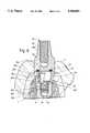
- FIG. 2shows a section through the jaw bone shown in FIG. 1 and a base and through an abutment screwed into said base and a shell present in the hole,
- FIG. 3shows a separate representation of the shell, drawn partly in section and partly as a view
- FIG. 4shows a plan view of the shell end present in FIGS. 2 and 3
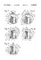
- FIG. 5shows a section, corresponding to FIG. 2, through a device having a differently designed shell
- FIG. 6shows a section, corresponding to FIG. 2, through a device having a shell of yet another design
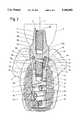
- FIG. 7shows a device which is drawn partly as a view and partly in section and whose abutment has a multiedged peg for holding the dental prosthesis
- FIG. 8shows a device which is drawn partly as a view and partly in section and whose abutment has a retentive anchor
- FIG. 9shows a representation of another device having a retentive anchor
- FIG. 10shows a device whose abutment contains a magnetic coupling element
- FIG. 11shows a device having an abutment formed for soldering on a dental prosthesis.
- FIGS. 1 and 2show a jaw bone 1 having a hole 1a entering its ridge.
- the hole 1ais in the form of a blind hole and has a base section which consists of an annular groove and is adjacent to a cylindrical bore which is hollow in the entire circular cross-section.
- An extensionwhich widens toward the mouth and whose limiting surface is continuously curved in axial section is present between said bore and the mouth of the hole 1a.
- the bore section formed by the annular groove in the cylindrical boreis provided with an internal thread.
- FIGS. 1 and 2furthermore show the gingiva 2.
- the gingivais cut open in such a way that gingiva flaps designated by 2a and 2b in FIG. 1 can be folded away.
- the hole 1ais then produced by drilling and cutting.
- a device for fixing the dental prosthesisis designated as a whole by 3 in FIG. 2 and has three parts detachably connected to one another, namely a base 4 also shown in FIG. 1 and frequently designated the primary part or implant, an abutment 5 also designated, for example, as the secondary part and a shell 6.
- a base 4also shown in FIG. 1 and frequently designated the primary part or implant
- an abutment 5also designated, for example, as the secondary part and a shell 6.
- the elongated base 4has a cylindrical section 4a which is provided with an external thread 4b. Adjacent to the cylindrical section 4a is a section 4c which thickens in a trumpet-like manner away from said section 4a.
- the lateral surface section 4r bordering said section 4c externallyis uniformly and continuously curved, as in the case of the surface which borders the stated extension of the hole 1a.
- the lateral surface section 4r of the section 4cmakes an angle of at most 30° and, for example, about 15° to 25° with said axis. That end of the base 4 which is located in FIGS.
- the base 4is provided with a hole 4e which is coaxial with the axis 7, consists of a blind hole and has a mouth in the end face 4d.
- the hole 4ehas a cylindrical base section 4f which is provided, at least in one part, with an internal thread 4g and therefore forms a threaded hole.
- the hole 4ehas, between the internal thread 4g and the end face 4d, an extension 4h which widens toward said end face and is bordered, at least for the most part, by a conical inner surface 4i which makes an angle of, preferably, at least 5° and, preferably, at most 15° with the axis 7.
- the end face 4dis formed by an end face which encloses the mouth of the hole 4e and consists, at least for the most part, of an annular surface 4k which is inclined away from the axis 7 conically outward toward that end of the base which is opposite the end face 4d.
- the outer edge 4m of said annular surfacealso forms the outer edge of the end face 4d.
- the angle of inclination between the conical annular surface 4k and the axis 7is about 20° to 70° and namely, for example, about 45°.
- the annular surface 4kmakes an obtuse angle with that end of the lateral surface section 4r which is adjacent to the outer edge 4m of said annular surface, said lateral surface section being curved in axial section.
- the cylindrical section 4a of the base 4furthermore has a hole 4n which is coaxial with the axis 7, consists of a blind hole and has a mouth at that end of the base 4 which is opposite the end face 4d.
- the cylindrical section 4ais furthermore provided with some holes 4p which pass through its lateral surface and enter the hole 4n.
- the base 4consists of a one-piece member comprising a metallic material, namely titanium.
- the cylindrical section 4ais also provided with, for example, a coating applied by a plasma coating method and likewise consisting of titanium.
- the elongated, one-piece, metallic abutment 5which consists, for example, of titanium, has an inner part 5a and an outer part 5b. If the abutment 5 is connected to the base 4 in the assembled device according to FIG. 2, the inner part 5a is located in the hole 4e of the base 4 while the outer part 5b is arranged outside the base 4.
- the inner part 5ahas a thread part 5c with an external thread 5d and an essentially cylindrical thick part 5e which is rotationally symmetrical with respect to the axis 7 and whose diameter is slightly larger than the external diameter of the external thread 5d.
- the thick part 5eis provided with a small bevel at its end facing the thread part 5c.
- the outer part 5dconsists of an even thicker covering section 5f adjacent to the thick part 5e.
- Said covering sectionis bordered, at its end facing the base 4, by an annular surface, of which at least the outermost part serves as a conical stop surface 5g. This makes the same angle with the axis 7 as the annular surface 4k of the base 4 and rests against the annular surface 4k in the assembled device.
- the outer edge of the stop surface 5g and the cylindrical lateral surface section 5h of the covering section 5f, which lateral surface section is adjacent to this outer edge,have the same diameter as the outer edge 4m of the annular surface 4k.
- the lateral surface section 5hmakes an acute angle with the stop surface 5g and, in the assembled device, also with the annular surface 4k of the base 4.
- the sum of this angle and the obtuse angle made by the surfaces 4k and 4r of the baseis between 125° and 180° and is, for example, at least 150°.
- a conical end section 5i which tapers away from the covering section 5fis adjacent to said covering section.
- the conical lateral surface of said end sectionis connected at its further end by a likewise conical shoulder surface 5k to the cylindrical lateral surface section 5h of the covering section 5f and, together with the shoulder surface 5k, forms a shoulder having an obtuse angle in axial section.
- the length of the cylindrical lateral surface section 5h and the distance of the shoulder surface 5k from the stop surface 5gis preferably at least 2 mm, preferably up to about 5 mm and, for example, about 3 mm.
- the abutment 5is also provided with an axial threaded blind hole 5m which has a mouth at the free end of the end section 5i.
- the one-piece, metallic shell 6which is shown separately in FIGS. 3 and 4 and consists, for example, of titanium has, in its middle region, a conical outer surface 6a which widens in an upward direction in FIGS. 2 and 3 and makes the same angle with the axis 7 as the conical inner surface 4i of the base 4.
- a bevel 6bwhich tapers toward the lower end of the shell 6, is likewise conical but makes a larger angle with the axis 7 is adjacent to that end of the conical outer surface 6a which is located at the bottom in FIGS. 2 and 3.
- a cylindrical outer surface 6cwhich has the same diameter as the further end of the conical outer surface 6a is adjacent to the upper end of the conical outer surface 6a.
- a bevel 6d which tapers toward the upper end of the shellis present on the upper end of the cylindrical surface 6c.
- the shell 6has an axial through-hole 6e whose section located at the bottom in FIGS. 2 and 3 is provided with an internal thread 6f.
- the hole 6ehas an extension 6g above the internal thread 6f.
- the boundary of said extensionhas a transition surface adjacent to the internal thread and arc-shaped in axial section, a cylindrical inner surface above said transition surface and, at the very top, a conical surface widening upward toward the mouth.
- the diameter of the cylindrical inner surfaceis slightly--for example about 0.01 mm to 0.05 mm--smaller than the diameter of the cylindrical surface of the thick part 5e of the abutment 5.
- the extension 6eextends from its end forming the upper mouth of the hole 6e into that region of the shell which is bordered on the outside by the upper end section of the conical outer surface 6a.
- That section of the lateral surface of the shell 6 which encloses the extension 6gis divided into a plurality of segments 6i, namely four such segments, which are uniformly distributed along the circumference of the shell, by slots 6h which are parallel to the axis 7 and enter the upper end of the shell.
- Said segmentsare slightly elastically deformable so that they can be spread away from the axis 7, starting from the position which they assume in the relaxed state.
- the base 4is inserted into the hole 1a and screwed into the internal thread of the hole 1a with the aid of an inserting tool.
- the base 4adopts the position which is shown in FIG. 1 and in which the outer edge 4m of the annular surface 4k is located approximately at the edge of the mouth of the hole 1a.
- the end face 4d of the base 4then projects, for example, slightly out of the hole 1a and/or is more or less exactly flush with that surface of the jaw bone 1 which encloses the hole 1a.
- a closure screw 8 drawn above the base 4 in FIG. 1has a thread part 8a, which can be screwed into the internal thread 4g, and a head 8b. This has, on its side facing the base 4, a conical surface 8c which makes the same angle with the axis 7 as the conical annular surface 4k and has the same external diameter as the latter.
- the screw 8can be screwed into the hole 4e of the base 4 so that it rests with its conical surface 8c on the annular surface 4k of the base 4 and closes the hole 4e.
- the gingiva flaps 2a, 2bcan then be placed over-the base 4 and the screw 8 and sutured.
- the base and the screwcan then be left in the jaw bone 1 during a healing period or phase which lasts, for example, for a few months.
- the jaw bonecan then heal and to a certain extent intergrow with the base 4 and in particular also grow through its holes 4p in the manner indicated in FIG. 2.
- the gingiva 2does of course also heal and grows together over the base.
- the gingiva 2can be cut open again and the screw 8 unscrewed from the base 4.
- the shell 6is screwed onto the thread part 5c of the abutment 5 in such a way that the shell 6 is closer to the free end of the thread part than subsequently when the device has been completely assembled.
- the free end section of the abutment thread part 5c, which section projects from the lower end of the shell,is then screwed, with the aid of an insertion tool engaging the abutment, into that section of the hole 4e of the base 4 which is provided with the internal thread 4g.
- the shell 6is turned until its conical outer surface 6a rests firmly against the conical inner surface 4i of the base 4, and then remains in its axial position.
- the thread part 5ccan also be screwed more deeply into the base 4 until the conical stop surface 5g of the abutment 5 rests against the annular surface 4k of the base 4.
- the cylindrical thick part 5e of the abutment 5penetrates, at the latest in the final part of the insertion process, into the extension 6g of the hole 6e of the shell 6 and spreads the segments 6i of the shell 6 outward away from the axis 7.
- the originally cylindrical outer surface 6c forming a part of the outer boundary of the segments 6iis inclined slightly toward the axis 7 and is given a more or less conical shape, but is shown as a cylindrical surface in FIG. 2.
- their outer surfacesare additionally pressed, at least partly, against the conical inner surface 4i of the base 4.
- a dental prosthesis 9 indicated by a dash-dot line and in simplified form in FIG. 2can be fixed to the outer part 5b of the abutment 5.
- the end section 5i of the abutment 5can project into the dental prosthesis 9 in such a way that the latter rests on the shoulder surface 5k. Otherwise, the dental prosthesis may have a screw which is not shown and which is screwed firmly into the threaded hole 5m.
- the abutment 5 and the shell 6are assembled according to FIG. 2 to give a device 3, and the thread part 5c of the abutment 5 is screwed through the hole 6e of the shell 6 to the internal thread 4g of the base 4, the shell 6 which is likewise screwed to the thread part 5c of the abutment 5 fits firmly in the extension 4h of the hole 4e of the base 4 and rests with the conical outer surface 6a against the conical inner surface 4i of the base. Furthermore, the outer part 5b of the abutment 5 rests with the conical stop surface 5g on the conical annular surface 4k of the base 4.
- both conical surfaces 4i and 4k of the base 4rest tightly and firmly against the conical surfaces 6a and 5g of the shell 6 and of the abutment 5, respectively, in the assembled device.
- the segments 6i of the shell 6 which have been spread by the abutment 5are firmly clamped between the abutment and the base.
- the abutment 5is therefore connected in a very stable manner to the base 4, and the connection can in particular absorb both large compressive forces parallel to the axis 7 and large forces directed transverse to the axis 7 or can transmit said forces from the abutment to the base.
- the static frictional forces, compressive forces and clamping forces which are active between the various partsensure in particular that the abutment itself does not unscrew from the base 4.
- the conical annular surface 4k of the base 4 and the conical stop surface 5g of the abutmentare completely rotationally symmetrical with respect to the axis 7 and are completely smooth around said axis, i.e. are not interrupted by slots or grooves or the like.
- the surfaces 4k, 5gtherefore rest against one another, without gaps, around the axis 7 and the mouth of the hole 4e of the base 4.
- the covering section 5ffurthermore covers the end face 4d of the base 4, which end face is present below the gingiva 2, up to the outer edge 4m of the annular surface 4k.
- the covering section 5f of the abutmentabuts the edge 4m of the base 4 essentially without joints and without gaps. At the abutment point--i.e.
- FIG. 5shows a jaw bone 1, a gingiva 2 and a device designated by 13.
- the latterhas a base 4 which is identical or similar to that of the device 3 shown in FIG. 2.
- the abutment 5 of the device 13can likewise be identical or similar to that of the device 3 and possesses in particular an essentially cylindrical thick part 5e.
- the device 13has a shell 16 which differs from the shell 6 of the device 3.
- the conical outer surface 16aextends from the conical bevel 16b present at the lower end of the shell to the upper end of the shell 16. The latter thus has no outer surface corresponding to the cylindrical outer surface 6c.
- the shell 16has an axial through-hole 16e which has an internal thread 16f at the bottom and, at the top, an extension 16g which is partly bordered or formed by a cylindrical inner surface.
- the diameter of this cylindrical inner surfaceis not smaller than the diameter of the cylindrical thick part 5e but at least equal to this last-mentioned diameter.
- no slots corresponding to the slots 6hare present in the shell 16, so that the lateral surface of the shell 16 completely encloses its axis everywhere.
- the device 13When it is used, the device 13 can be assembled analogously to the device 3. Although the shell 16 of the device has no segments corresponding to the spreadable segments 6i of the shell 6, it still gives a stable connection between the abutment and the base. Since the shell 16 is formed in a somewhat simpler manner than the shell 6, it can be produced more economically than the latter. Otherwise, the device 13 has properties similar to those of the device 3.
- the device 23 shown in FIG. 6has a base 4 which in turn is formed identically or similarly to that of the device 3 and in particular has a hole 4e with an internal thread 4g and an extension 4h.
- the abutment 25 of the device 23has an inner part 25a and an outer part 25b.
- the inner part 25ahas a thread part 25c with an external thread 25d and an essentially cylindrical thick part 25e.
- the abutment 25differs from the abutment 5 in that the external thread 25d is shorter than the external thread 5d.
- the abutment 25While the latter extends, in the case of the abutment 5, almost to its thick part, the abutment 25 also possesses, between the external thread 25d and the thick part 25e, a threadless shaft 25n whose diameter is, for example, identical to the nominal or external diameter of the external thread 25d or only very slightly larger than the last-mentioned diameter.
- the shell 26 belonging to the device 23has a conical outer surface 26a which extends from a bevel 26b present at the thinner, lower end of the shell to the upper, further end of the shell 26.
- the shell 26furthermore has an axial through-hole 26e.
- Thishas a smooth, i.e. threadless, cylindrical section 26f instead of the internal thread 6f of the shell 6. Its diameter is approximately equal to the diameter of the shaft 25n, so that the latter fits tightly, or with at most very little radial play, into the cylindrical section 26f.
- the hole 26ehas an extension 26g above the section 26f. Said extension is partly formed by a cylindrical inner surface whose diameter is at least equal to the diameter of the cylindrical thick part 25e of the abutment 25. Otherwise, the shell 26 has no slots corresponding to the slots 6h of the shell 6.
- the device 23may additionally have an elastomeric ring 28 which may consist, for example, of a biocompatible, sterilizable, O-ring. This ring 28 may be arranged between that surface of the abutment 5 which covers the mouth of the hole 4e of the base 4 and the radial annular surface which faces said surface of the abutment 5 and is present at the further end of the shell 26.
- an elastomeric ring 28which may consist, for example, of a biocompatible, sterilizable, O-ring. This ring 28 may be arranged between that surface of the abutment 5 which covers the mouth of the hole 4e of the base 4 and the radial annular surface which faces said surface of the abutment 5 and is present at the further end of the shell 26.
- the shell 26, for example in the state separated from the abutment 25,can be pressed into the extension 4h of the hole 4e of the base 4 and/or gently tapped into the extension 4h. Thereafter, the elastomeric ring 28 can be inserted into the top of the extension 4h and the thread part 25c of the abutment 25 can be screwed through the shell 26 and into the internal thread 4g of the base. That section of the inner part 25a which consists of the thick part 25e and the shaft 25n then passes through the shell 26. The shell 26 then furthermore rests with its conical outer surface 26a against the conical inner surface of the extension 4h, fits tightly into the latter and is moreover secured by the ring 28 against upward, axial displacements.
- the device 23has properties similar to those of the device 3.
- FIG. 7shows parts of a jaw bone 1, the gingiva 2 and a device 23.
- the latterhas a base 4, an abutment 35 and a shell 6.
- the base 4, the inner part 35a of the abutment 35 and the shell 6are identical or similar to those in the device 3.
- the outer part 35b of the abutment 35differs from the outer part 5b of the abutment 5 and possesses, on that side of the cylindrical covering section 35f which is opposite the base 4, an end section having a multiedged peg 35i which, in an axial view, forms, for example, a regular octagon.
- a conical shoulder surface which tapers toward the multiedged peg 35i and together with the latter forms a shoulderis present between the covering section 35f and said peg. Otherwise, the abutment 35 is provided with a threaded blind hole 35m having a mouth in the end face of the multiedged peg.
- FIG. 8shows parts of a jaw bone 1, the gingiva 2 and a device 43. Its base 4 and shell 6 are identical to those in the device 3.
- the abutment 45 of the device 43has an inner part 45a which is identical to that in the device 3.
- the outer part 45b of the abutment 45has a cylindrical covering section 45f and, on its side opposite the base 4, a retentive anchor 45i and a neck 45m connecting said anchor to the remaining abutment.
- the covering section 45fhas, on the side opposite the inner part 45a , a shoulder surface 45k which encloses the neck 45m, forms a shoulder together with said neck and has an inner, flat section which is at right angles to the axis 7 and a section which is inclined outward away from the retentive anchor and is, for example, conical.
- the base 4has a completely subgingival arrangement.
- the device shown in FIG. 9has a base 4 which projects substantially out of the jaw bone and passes at least substantially through the gingiva 2 after the latter has healed, so that the end face of the base 4 is approximately flush with the boundary of the gingiva 2, which boundary is opposite the jaw bone 1, and/or is located outside the gingiva.
- the base 4 of the device 53can be formed identically to the base of the devices 3, 13, 23, 33, 43 or may have a slightly longer cylindrical section 4a and a correspondingly longer external thread 4b.
- the abutment 55 of the device 53has an inner part 55a which is identical to that in the abutment 5.
- the outer part 55b of the abutment 55has a covering section 55f and a retentive anchor 55i connected to said covering section by a neck 45m.
- the covering section 55fhas a shoulder surface 55k enclosing the neck 55m.
- the abutment 55thus has a retentive anchor as in the case of the abutment 45, but differs from the latter in that its covering section 55f has a substantially shorter axial dimension than the covering section of the abutment 45.
- the covering section 55fhas a lateral surface section which is arc-shaped in axial section and has, at its end located at the outer edge of the conical annular surface 4k of the base 4, an approximately continuous connection to the lateral surface of the base and, at the other end, goes over continuously into a flat section of the shoulder surface 55k, which section is at right angles to the axis 7.
- the shell of the device 53is identical to that in the device 3.
- the devices 43 and 53 having a retentive anchor 45i and 55i, respectively,permit the fixing of a dental prosthesis with a closure element into which the retentive anchor can be detachably snapped similarly to a press stud closure.
- a dental prosthesis not shown in FIGS. 8, 9is detachably clipped to the abutments 45, 55, for example, a gap-like intermediate space may be present between said prosthesis and the shoulder surface 45k or 55k.
- the shoulder surfaces 45k, 55kmay readily be so far away from the jaw bone that, in spite of the intermediate space mentioned, the gingiva scarcely goes over them and they can be readily cleaned.
- the abutments 45, 55are connected in a stable manner to the base 4--as explained in detail for the abutment 5.
- the device 63 shown in FIG. 10has a base 4, an abutment 65 and a shell 6.
- the base 4is once again identical or similar to that of the device 3 but, analogously to the device 53, is inserted into a jaw bone 1 in such a way that it at least essentially penetrates the gingiva after the latter has healed.
- the shell 6is identical to that in the device 3.
- the abutment 65has an inner part 65a which is formed identically to that in the abutment 5.
- the outer part 65b of the abutment 65possesses a lateral surface section having an approximately continuous connection to the lateral surface of the base 4 and extending away therefrom and, at its end opposite the base 4, an end section 65i which tapers, for example slightly conically, toward its free end and is provided with a recess 65m in its end face.
- Said recesscontains a magnetic coupling element 68 which consists of at least one originally separate member connected rigidly and preferably nondetachably to the remainder of the abutment 65.
- the magnetic coupling element 68is ferromagnetic and has at least one permanent magnet and/or at least one magnetically soft member.
- the abutment 65 of the device 63serves for holding a dental prosthesis which is not shown in FIG. 10 and which likewise has a ferromagnetic coupling element which, in cooperation with the magnetic coupling element 68, permits a detachable connection between the dental prosthesis and the abutment 65. At least one of the two cooperating magnetic coupling elements must have a permanent magnet.
- the device 73 shown in FIG. 11has a base 4 projecting out of a jaw bone 1 and passing through the gingiva 2, a shell 6 and an abutment 75, the base 4, the shell 6 and the inner part 75a of the abutment 75 being idetnical or similar to those in the device 3.
- the outer part 75b of the abutment 75has a covering section 75f covering the end face of the base 4 and, at its end opposite the base, a shoulder surface 75k making at least approximately a right angle with the axis 7 and a projection or continuation 75i which projects away from said shoulder surface, is coaxial with the axis 7 and, for example, consists of a cylindrical pin.
- the projection or continuation 75ican project into a dental prosthesis, which is not shown.
- the dental prosthesis or at least a part thereofcan rest on the shoulder surface 75k forming a shoulder together with the projection or continuation and can be soldered to the abutment 75 at said shoulder surface.
- the soldering processis preferably carried out with the abutment 75 separated from the base 4.
- the devices 3, 13, 23, 33, 73 described with reference to FIGS. 1 to 7 and 11can alternatively be used for fixing a dental prosthesis which has only a single artificial tooth or a plurality of artificial teeth.
- the devices 43 or 53 or 63 having a retentive anchor 45i, 55i or a magnetic coupling element 68are intended, together with at least one other device of the same type, for detachably fixing a dental prosthesis having a plurality of teeth, i.e. a bridge or a denture.
- the jaw bone 1 shown in various Figuresconsists of a mandible from which the devices project on the upper side. However, the devices can also be inserted into a maxilla and then project downward from this.
- a dentist or surgeon using devicescan be provided with a set of bases 4 of different lengths and thicknesses so that the dentist or surgeon can select a base having a length and diameter adapted to the individual characteristics of the jaw bone.
- abutments 5 having covering sections 5f of different lengthscan be provided so that a dentist or surgeon can select an abutment where the length of the covering section is adapted to the individual thickness of the gingiva. The same also applies to the abutments 25, 35, 45.
- the axial hole 4n having a mouth at its end opposite the abutment, and the radial holes 4p,can be omitted.
- the external thread 4bmay be omitted in the base 4.
- the basemay be slightly angled so that the axis of the section 4c widening in a trumpet-like manner and of the hole 4e makes an angle with the axis of that end section of the base which is opposite the end face 4d.
- a ring corresponding to the elastomieric ring 28 of the device 23may also be provided in the device 13 shown in FIG. 5 or, on the other hand, the ring 28 can be omitted in the device 23.
- the inner part of the abutment and the shells of the devices shown in FIGS. 7 to 11could be similar to identical to those in the devices 13 or 23.
Landscapes
- Health & Medical Sciences (AREA)
- Oral & Maxillofacial Surgery (AREA)
- Orthopedic Medicine & Surgery (AREA)
- Dentistry (AREA)
- Epidemiology (AREA)
- Life Sciences & Earth Sciences (AREA)
- Animal Behavior & Ethology (AREA)
- General Health & Medical Sciences (AREA)
- Public Health (AREA)
- Veterinary Medicine (AREA)
- Dental Prosthetics (AREA)
Abstract
Description
Claims (31)
Priority Applications (2)
| Application Number | Priority Date | Filing Date | Title |
|---|---|---|---|
| EP93810425AEP0629384B1 (en) | 1993-06-14 | 1993-06-14 | Device for fixing a dental prosthesis to a jaw bone |
| US08/095,119US5368483A (en) | 1993-06-14 | 1993-08-20 | Device-for fixing a dental prosthesis to a jaw bone |
Applications Claiming Priority (2)
| Application Number | Priority Date | Filing Date | Title |
|---|---|---|---|
| EP93810425AEP0629384B1 (en) | 1993-06-14 | 1993-06-14 | Device for fixing a dental prosthesis to a jaw bone |
| US08/095,119US5368483A (en) | 1993-06-14 | 1993-08-20 | Device-for fixing a dental prosthesis to a jaw bone |
Publications (1)
| Publication Number | Publication Date |
|---|---|
| US5368483Atrue US5368483A (en) | 1994-11-29 |
Family
ID=26134824
Family Applications (1)
| Application Number | Title | Priority Date | Filing Date |
|---|---|---|---|
| US08/095,119Expired - LifetimeUS5368483A (en) | 1993-06-14 | 1993-08-20 | Device-for fixing a dental prosthesis to a jaw bone |
Country Status (2)
| Country | Link |
|---|---|
| US (1) | US5368483A (en) |
| EP (1) | EP0629384B1 (en) |
Cited By (115)
| Publication number | Priority date | Publication date | Assignee | Title |
|---|---|---|---|---|
| US5492471A (en)* | 1994-03-23 | 1996-02-20 | Gary Singer | Healing cap system |
| US5580246A (en)* | 1995-01-30 | 1996-12-03 | Fried; Paula S. | Dental implants and methods for extending service life |
| WO1997014371A1 (en)* | 1995-10-13 | 1997-04-24 | Institut Straumann Ag | Connector between an implant and an abutment |
| US5688123A (en)* | 1994-05-04 | 1997-11-18 | Degussa Aktiengesellschaft | Transfer cap for dental implants |
| US5759034A (en)* | 1996-11-29 | 1998-06-02 | Daftary; Fereidoun | Anatomical restoration dental implant system for posterior and anterior teeth |
| US5810590A (en)* | 1995-01-30 | 1998-09-22 | Fried; Paula S. | Dental implants and methods for extending service life |
| US5829977A (en)* | 1995-05-25 | 1998-11-03 | Implant Innovations, Inc. | Two-piece dental abutment |
| US5846079A (en)* | 1996-02-29 | 1998-12-08 | Implant Innovations, Inc. | Single tooth dental restoration system |
| US5863201A (en)* | 1994-11-30 | 1999-01-26 | Implant Innovations, Inc. | Infection-blocking dental implant |
| US5873722A (en)* | 1996-02-02 | 1999-02-23 | Implant Innovations, Inc. | Emergence profile system having a combined healing abutment and impression coping |
| US5876453A (en)* | 1994-11-30 | 1999-03-02 | Implant Innovations, Inc. | Implant surface preparation |
| US5899695A (en)* | 1994-11-08 | 1999-05-04 | Lazzara; Richard J. | Anatomic interchangeable healing abutment and impression coping |
| ES2129336A1 (en)* | 1996-11-29 | 1999-06-01 | Univ De A Coruna | Osteo-integrable dental prosthesis with implantation and fixing by levers and spigots |
| US5938443A (en)* | 1994-11-08 | 1999-08-17 | Implant Innovations, Inc. | Impression coping for use in an open tray and closed tray impression methodology |
| US5947732A (en)* | 1994-06-16 | 1999-09-07 | Implant Innovations, Inc. | Support post for use in dental implant system |
| US5989026A (en)* | 1995-05-25 | 1999-11-23 | Implant Innovations, Inc. | Ceramic two-piece dental abutment |
| US5989028A (en)* | 1997-05-15 | 1999-11-23 | Core-Vent Corporation | Non-submergible, one-part, root-form endosseous dental implants |
| WO2000009031A1 (en)* | 1998-08-12 | 2000-02-24 | Nobel Biocare Ab | One-step threaded implant |
| EP0922439A3 (en)* | 1997-12-12 | 2000-05-17 | Francesco Faraci | Improved screw for intraosseus implant |
| US6120292A (en)* | 1995-12-04 | 2000-09-19 | Institut Straumann Ag | Healing cap for dental implants |
| US6162054A (en)* | 1998-01-28 | 2000-12-19 | Takacs; Gyula | Subgingival jaw implant |
| US6168435B1 (en) | 1998-10-26 | 2001-01-02 | Implant Innovations, Inc. | Ceramic dental abutments with a metallic core |
| US6217331B1 (en) | 1997-10-03 | 2001-04-17 | Implant Innovations, Inc. | Single-stage implant system |
| USRE37227E1 (en) | 1991-09-18 | 2001-06-12 | Implant Innovations, Inc. | Device for the reconstruction of teeth |
| US6280195B1 (en) | 1999-06-11 | 2001-08-28 | Astra Aktiebolag | Method of treating a partially or totally edentulous patient |
| US6290500B1 (en)* | 1997-12-10 | 2001-09-18 | Diro, Inc. | Dental implant system and method |
| US6350732B1 (en) | 1987-08-02 | 2002-02-26 | Carbomedics, Inc. | Method for extracting lipids from tissue samples using high osmolality storage medium and product |
| ES2169689A1 (en)* | 2000-10-05 | 2002-07-01 | Impladent S L | Anatomical, conical-radio dental implant |
| US6461160B1 (en)* | 1998-07-29 | 2002-10-08 | Franz Sutter | Device for holding and/or creating a dental prosthesis |
| US6464500B1 (en)* | 2001-05-22 | 2002-10-15 | Don Dragoljub Popovic | Dental implant and abutment system |
| US6491723B1 (en) | 1996-02-27 | 2002-12-10 | Implant Innovations, Inc. | Implant surface preparation method |
| US6506051B2 (en)* | 2000-09-01 | 2003-01-14 | Ricardo Levisman | Bone implant with intermediate member and expanding assembly |
| US6558162B1 (en) | 1999-11-10 | 2003-05-06 | Implant Innovations, Inc. | Healing components for use in taking impressions and methods for making the same |
| US6561805B2 (en) | 1999-08-12 | 2003-05-13 | Nobel Biocare Ab | Universal implant delivery system |
| EP1243229A3 (en)* | 2001-03-23 | 2003-05-21 | Dr.-medic-stom./UMF Temeschburg, Herbert Hatzlhoffer | Dental implant |
| US6604945B1 (en)* | 1994-08-15 | 2003-08-12 | Shedrick D. Jones | Method and apparatus for implantation |
| US20030181603A1 (en)* | 2002-03-19 | 2003-09-25 | General Electric Company | Resinous compositions, method of manufacture thereof and articles fabricated from the composition |
| US6652765B1 (en) | 1994-11-30 | 2003-11-25 | Implant Innovations, Inc. | Implant surface preparation |
| US6663388B1 (en) | 1998-12-28 | 2003-12-16 | Institut Straumann Ag | Connection between a dental implant and an abutment |
| US6666685B2 (en)* | 2001-02-19 | 2003-12-23 | Plauto Pires De Almeida Filho | Disposition introduced in an assembly of elements used in osteo-integrated implants |
| US20040038179A1 (en)* | 2001-12-07 | 2004-02-26 | Ajay Kumar | Healing abutment |
| US20040043358A1 (en)* | 2002-01-11 | 2004-03-04 | Howlett Charles W. | Dental implant delivery system |
| US6709270B2 (en)* | 2001-12-27 | 2004-03-23 | Aichi Steel Corporation | Dental magnetic attachment |
| US6758672B2 (en) | 2000-01-18 | 2004-07-06 | Implant Innovations, Inc. | Preparation coping for creating an accurate permanent post to support a final prosthesis and method for creating the same |
| US6769913B2 (en) | 2000-08-30 | 2004-08-03 | Nobel Biocare Ab | Impression cap |
| US6790040B2 (en) | 1999-11-10 | 2004-09-14 | Implant Innovations, Inc. | Healing components for use in taking impressions and methods for making the same |
| US20040185419A1 (en)* | 2003-03-18 | 2004-09-23 | Schulter Carl W. | Unitary dental implant |
| US20040185418A1 (en)* | 2003-03-18 | 2004-09-23 | Schulter Carl W. | Dental implant fixture |
| US20050023166A1 (en)* | 2003-07-31 | 2005-02-03 | Howlett Charles W. | Dental implant packaging system |
| USRE38945E1 (en) | 1995-01-30 | 2006-01-24 | Paula S. Fried | Dental implants and methods for extending service life |
| US20060105296A1 (en)* | 2004-11-16 | 2006-05-18 | Straumann Holding Ag | Dental implant system |
| US20060127849A1 (en)* | 2004-12-15 | 2006-06-15 | Ricardo Levisman | Dental implant system |
| US20070092854A1 (en)* | 2005-10-24 | 2007-04-26 | Powell Theodore M | Methods for manufacturing dental implant components |
| US20070275351A1 (en)* | 2006-05-29 | 2007-11-29 | Kwang-Bum Park | Healing Abutment and Dental Implant Having the Same |
| US7338286B2 (en) | 2002-11-13 | 2008-03-04 | Biomet 3I, Inc. | Dental implant system |
| US7344376B2 (en) | 1997-04-09 | 2008-03-18 | Biomet 3I, Inc. | Implant delivery system |
| WO2009007401A3 (en)* | 2007-07-09 | 2009-03-05 | Lindberg Implants Ab | A healing abutment, a screw and a method |
| US20090191508A1 (en)* | 2008-01-25 | 2009-07-30 | Kyoung-Soo Choi | Mini implant |
| US20090298015A1 (en)* | 2008-05-28 | 2009-12-03 | Global Implant Solutions, Llc | Digital Abutment For Dental Implant System |
| US7632095B2 (en) | 2007-08-13 | 2009-12-15 | Biomet 3I, Inc. | Method for forming a dental prosthesis |
| US20100015571A1 (en)* | 2008-07-15 | 2010-01-21 | Global Implant Solutions, Llc | Flexible Abutment For Use With A Dental Implant |
| US20100119995A1 (en)* | 2007-03-14 | 2010-05-13 | Grant Bethany F | Dental abutment including fillet |
| US20100311013A1 (en)* | 2005-02-11 | 2010-12-09 | Niznick Gerald A | One-piece, screw-receiving, externally-threaded endosseous dental implants and related transfer components, comfort caps and abutments |
| US7887327B2 (en) | 2001-08-31 | 2011-02-15 | Leonard Marotta | Accurate analogs for prostheses using computer generated anatomical models |
| US20110076644A1 (en)* | 2008-04-18 | 2011-03-31 | Neoss Limited | Locking Ring |
| WO2010141342A3 (en)* | 2009-06-01 | 2011-04-21 | University Of Maryland, Baltimore | Snap-on two-piece emergence profile healing abutment |
| US20110097687A1 (en)* | 2008-04-18 | 2011-04-28 | Neoss Limited | Spacer Element |
| US20110123950A1 (en)* | 2006-06-27 | 2011-05-26 | Dana Alan Carlton | Dental Implant and Positioning Device Therefor |
| US8033826B2 (en) | 2007-11-15 | 2011-10-11 | Biomet 3I, Llc | Two-piece dental abutment system |
| EP2382943A1 (en)* | 2010-04-29 | 2011-11-02 | nt-trading GmbH & Co. KG | Abutment for an implant system |
| US8185224B2 (en) | 2005-06-30 | 2012-05-22 | Biomet 3I, Llc | Method for manufacturing dental implant components |
| USRE43470E1 (en) | 1995-11-17 | 2012-06-12 | Nobel Biocare Services, Ag | Dental implant systems and methods |
| US8206153B2 (en) | 2007-05-18 | 2012-06-26 | Biomet 3I, Inc. | Method for selecting implant components |
| US8221121B2 (en) | 2008-04-16 | 2012-07-17 | Biomet 3I, Llc | Method for pre-operative visualization of instrumentation used with a surgical guide for dental implant placement |
| US8251700B2 (en) | 2003-05-16 | 2012-08-28 | Biomet 3I, Llc | Surface treatment process for implants made of titanium alloy |
| US8257083B2 (en) | 2005-10-24 | 2012-09-04 | Biomet 3I, Llc | Methods for placing an implant analog in a physical model of the patient's mouth |
| CN102781364A (en)* | 2010-02-26 | 2012-11-14 | 诺贝尔生物服务公司 | Attachment member and a dental restoration |
| US8454363B2 (en) | 2008-11-06 | 2013-06-04 | William B. Worthington | Dental implant system |
| US8562348B2 (en)* | 2008-07-02 | 2013-10-22 | Zimmer Dental, Inc. | Modular implant with secured porous portion |
| WO2013169569A1 (en)* | 2012-05-07 | 2013-11-14 | Chien-Ping Ju | Dental implant with cushion |
| US8651858B2 (en) | 2008-04-15 | 2014-02-18 | Biomet 3I, Llc | Method of creating an accurate bone and soft-tissue digital dental model |
| US20140127643A1 (en)* | 2011-07-11 | 2014-05-08 | Neobiotech Co., Ltd. | Frictional angled dental implant |
| US20140147812A1 (en)* | 2010-09-24 | 2014-05-29 | Zimmer Dental, Inc. | Dental implant and abutment system |
| US8777612B2 (en) | 2007-11-16 | 2014-07-15 | Biomet 3I, Llc | Components for use with a surgical guide for dental implant placement |
| US8790408B2 (en) | 2001-08-31 | 2014-07-29 | Leonard Marotta | Accurate analogs for bone graft prostheses using computer generated anatomical models |
| US8882508B2 (en) | 2010-12-07 | 2014-11-11 | Biomet 3I, Llc | Universal scanning member for use on dental implant and dental implant analogs |
| US8888486B2 (en) | 2010-09-23 | 2014-11-18 | Biomet 3I, Llc | Dental abutment system |
| US8926328B2 (en) | 2012-12-27 | 2015-01-06 | Biomet 3I, Llc | Jigs for placing dental implant analogs in models and methods of doing the same |
| US8944818B2 (en) | 2011-05-16 | 2015-02-03 | Biomet 3I, Llc | Temporary abutment with combination of scanning features and provisionalization features |
| WO2015066438A1 (en)* | 2013-11-01 | 2015-05-07 | Chien-Ping Ju | Double-cushioned dental implant |
| US20150147721A1 (en)* | 2012-05-09 | 2015-05-28 | Dentisel, S.L. | Dental prosthesis system |
| US20150196371A1 (en)* | 2014-01-13 | 2015-07-16 | Brock B. WESTOVER | Endosseous dental implant assembly |
| US9089382B2 (en) | 2012-01-23 | 2015-07-28 | Biomet 3I, Llc | Method and apparatus for recording spatial gingival soft tissue relationship to implant placement within alveolar bone for immediate-implant placement |
| US9452032B2 (en) | 2012-01-23 | 2016-09-27 | Biomet 3I, Llc | Soft tissue preservation temporary (shell) immediate-implant abutment with biological active surface |
| US20170027669A1 (en)* | 2014-04-22 | 2017-02-02 | T.A.G. Medical Devices - Agriculture Cooperative Ltd. | Dental implants |
| US9662186B2 (en) | 2012-12-21 | 2017-05-30 | Nobel Biocare Services Ag | Dental component with metal adapter |
| US9668833B2 (en) | 2012-12-21 | 2017-06-06 | Nobel Biocare Services Ag | Abutment and method of attaching an abutment to a dental implant |
| US9668834B2 (en) | 2013-12-20 | 2017-06-06 | Biomet 3I, Llc | Dental system for developing custom prostheses through scanning of coded members |
| US9700390B2 (en) | 2014-08-22 | 2017-07-11 | Biomet 3I, Llc | Soft-tissue preservation arrangement and method |
| US9724274B2 (en) | 2011-06-24 | 2017-08-08 | Straumann Holding Ag | Body made of ceramic material |
| US9839496B2 (en) | 2013-02-19 | 2017-12-12 | Biomet 3I, Llc | Patient-specific dental prosthesis and gingival contouring developed by predictive modeling |
| US9855122B2 (en) | 2001-08-31 | 2018-01-02 | Leonard Marotta | Accurate analogs for prosthesis using computer generated anatomical models |
| US9861455B2 (en) | 2013-07-30 | 2018-01-09 | TI Intellectual Property Inc. | Dental implant system |
| US9883926B2 (en)* | 2013-03-15 | 2018-02-06 | Harry A. HARALAMPOPOULOS | Conversion abutment for dental implants |
| US9925024B2 (en) | 2011-06-28 | 2018-03-27 | Biomet 3I, Llc | Dental implant and abutment tools |
| US10149741B2 (en) | 2012-12-21 | 2018-12-11 | Nobel Biocare Services Ag | Method of attaching a dental component to a dental implant |
| IT201700076961A1 (en)* | 2017-07-07 | 2019-01-07 | Plan 1 Health Srl | DENTAL PROSTHETIC DEVICE AND ITS INTERMEDIATE CONNECTION COMPONENT |
| US20190175310A1 (en)* | 2016-02-04 | 2019-06-13 | Holger Zipprich | Abutment, in particular for use with a dental implant inserted into the jaw bone of a patient, and method for producing the abutment |
| US10449018B2 (en) | 2015-03-09 | 2019-10-22 | Stephen J. Chu | Gingival ovate pontic and methods of using the same |
| US10813729B2 (en) | 2012-09-14 | 2020-10-27 | Biomet 3I, Llc | Temporary dental prosthesis for use in developing final dental prosthesis |
| US20200337811A1 (en)* | 2014-02-05 | 2020-10-29 | Straumann Holding Ag | Dental implant for bone collection and distribution |
| US11065090B2 (en) | 2013-04-09 | 2021-07-20 | Biom et 3I, LLC | Dental implant with coded upper surface |
| US11219511B2 (en) | 2005-10-24 | 2022-01-11 | Biomet 3I, Llc | Methods for placing an implant analog in a physical model of the patient's mouth |
| US20220039924A1 (en)* | 2019-05-06 | 2022-02-10 | TRI Dental Implants Int. AG | Superstructure, dental implant and dental prosthesis |
| EP4115847A4 (en)* | 2020-03-05 | 2024-04-03 | Implacil de Bortoli Material Odontológico | DENTAL IMPLANT |
Families Citing this family (4)
| Publication number | Priority date | Publication date | Assignee | Title |
|---|---|---|---|---|
| EP1444964B1 (en) | 1997-05-24 | 2007-01-10 | Straumann Holding AG | Support for sustaining and/or forming a dental prosthesis |
| US6159010A (en)* | 1998-04-23 | 2000-12-12 | Implant Innovations, Inc. | Fenestrated dental coping |
| DE10329207A1 (en)* | 2003-06-28 | 2005-01-13 | Ralf Dr. Schröder | Basic body for a dental implant, dental implant with basic body, implant post of a dental implant for introduction into the main body, dental implant with basic body and implant post and crown body for the implant post or the dental implant and packaging for dental implant |
| DE102013111842A1 (en)* | 2013-10-28 | 2015-04-30 | Universität Rostock | Mini screw for orthopedic reconstructions |
Citations (6)
| Publication number | Priority date | Publication date | Assignee | Title |
|---|---|---|---|---|
| US5026285A (en)* | 1989-05-31 | 1991-06-25 | Axel Kirsch | Enossal individual tooth implant and locking tool for use with such an implant |
| WO1991008713A1 (en)* | 1989-12-07 | 1991-06-27 | Zl Microdent-Attachment Gmbh | Threaded body for securing a multi-part tooth replacement |
| US5116225A (en)* | 1990-10-17 | 1992-05-26 | Riera Juan C A | Angulated abutment for osseointegrated implants |
| US5125840A (en)* | 1990-09-08 | 1992-06-30 | Eberle Medizintechnische Element Gmbh | Enossal single tooth implant with twisting restraint |
| US5135395A (en)* | 1990-07-05 | 1992-08-04 | Marlin Gerald M | Implant collar and post system |
| US5246370A (en)* | 1992-11-27 | 1993-09-21 | Coatoam Gary W | Dental implant method |
Family Cites Families (4)
| Publication number | Priority date | Publication date | Assignee | Title |
|---|---|---|---|---|
| DE2413883C3 (en)* | 1974-03-22 | 1980-11-13 | Werner Lutz 3073 Liebenau Koch | Endosseous implant for the attachment of fixed dentures |
| CH642838A5 (en)* | 1979-11-21 | 1984-05-15 | Osteo Ag | JAW IMPLANT. |
| US4976739A (en)* | 1986-05-15 | 1990-12-11 | Duthie Jr Robert E | Implant system |
| US5110292A (en)* | 1990-08-30 | 1992-05-05 | Calcitek, Inc. | Endosseous implant system with internal jam nut |
- 1993
- 1993-06-14EPEP93810425Apatent/EP0629384B1/ennot_activeExpired - Lifetime
- 1993-08-20USUS08/095,119patent/US5368483A/ennot_activeExpired - Lifetime
Patent Citations (6)
| Publication number | Priority date | Publication date | Assignee | Title |
|---|---|---|---|---|
| US5026285A (en)* | 1989-05-31 | 1991-06-25 | Axel Kirsch | Enossal individual tooth implant and locking tool for use with such an implant |
| WO1991008713A1 (en)* | 1989-12-07 | 1991-06-27 | Zl Microdent-Attachment Gmbh | Threaded body for securing a multi-part tooth replacement |
| US5135395A (en)* | 1990-07-05 | 1992-08-04 | Marlin Gerald M | Implant collar and post system |
| US5125840A (en)* | 1990-09-08 | 1992-06-30 | Eberle Medizintechnische Element Gmbh | Enossal single tooth implant with twisting restraint |
| US5116225A (en)* | 1990-10-17 | 1992-05-26 | Riera Juan C A | Angulated abutment for osseointegrated implants |
| US5246370A (en)* | 1992-11-27 | 1993-09-21 | Coatoam Gary W | Dental implant method |
Non-Patent Citations (6)
| Title |
|---|
| "Bonefit Basic Information" pp. 1-6, Institute Strauman. |
| "Journal of Oral Implantalogy" vol. XVI, No. 4, 1990 pp. 297-301. |
| "The New Concept of ITI Hollow-Cylinder and Hollow Screw Impants:" 1988 Franz Sutter/Andre Schroeder, DDS, PhD Daniel A. Buser, DDS pp. 161-172. |
| Bonefit Basic Information pp. 1 6, Institute Strauman.* |
| Journal of Oral Implantalogy vol. XVI, No. 4, 1990 pp. 297 301.* |
| The New Concept of ITI Hollow Cylinder and Hollow Screw Impants: 1988 Franz Sutter/Andre Schroeder, DDS, PhD Daniel A. Buser, DDS pp. 161 172.* |
Cited By (231)
| Publication number | Priority date | Publication date | Assignee | Title |
|---|---|---|---|---|
| US6350732B1 (en) | 1987-08-02 | 2002-02-26 | Carbomedics, Inc. | Method for extracting lipids from tissue samples using high osmolality storage medium and product |
| USRE37227E1 (en) | 1991-09-18 | 2001-06-12 | Implant Innovations, Inc. | Device for the reconstruction of teeth |
| US5492471A (en)* | 1994-03-23 | 1996-02-20 | Gary Singer | Healing cap system |
| US5651675A (en)* | 1994-03-23 | 1997-07-29 | Gary Singer | Healing cap system |
| US5813858A (en)* | 1994-03-23 | 1998-09-29 | Phillip Singer | Healing cap system with implant alignment indicator |
| US5688123A (en)* | 1994-05-04 | 1997-11-18 | Degussa Aktiengesellschaft | Transfer cap for dental implants |
| US5947732A (en)* | 1994-06-16 | 1999-09-07 | Implant Innovations, Inc. | Support post for use in dental implant system |
| US6152737A (en)* | 1994-06-16 | 2000-11-28 | Implant Innovations, Inc. | Support post for use in dental implant system |
| US6604945B1 (en)* | 1994-08-15 | 2003-08-12 | Shedrick D. Jones | Method and apparatus for implantation |
| US6290499B1 (en) | 1994-11-08 | 2001-09-18 | Implant Innovations, Inc. | Transfer-type impression coping |
| US5899695A (en)* | 1994-11-08 | 1999-05-04 | Lazzara; Richard J. | Anatomic interchangeable healing abutment and impression coping |
| US6120293A (en)* | 1994-11-08 | 2000-09-19 | Implant Innovations, Inc. | Abutment for a temporary tooth |
| US5938443A (en)* | 1994-11-08 | 1999-08-17 | Implant Innovations, Inc. | Impression coping for use in an open tray and closed tray impression methodology |
| US5899697A (en)* | 1994-11-08 | 1999-05-04 | Implant Innovations, Inc. | Anatomic interchangeable healing abutment and impression coping |
| US7550091B2 (en) | 1994-11-30 | 2009-06-23 | Biomet 3I, Llc | Implant surface preparation |
| US6652765B1 (en) | 1994-11-30 | 2003-11-25 | Implant Innovations, Inc. | Implant surface preparation |
| US8221499B2 (en) | 1994-11-30 | 2012-07-17 | Biomet 3I, Llc | Infection-blocking dental implant |
| US6969474B2 (en) | 1994-11-30 | 2005-11-29 | Implant Innovations, Inc. | Implant surface preparation |
| US5876453A (en)* | 1994-11-30 | 1999-03-02 | Implant Innovations, Inc. | Implant surface preparation |
| US7857987B2 (en) | 1994-11-30 | 2010-12-28 | Biomet 3I, Llc | Implant surface preparation |
| US5863201A (en)* | 1994-11-30 | 1999-01-26 | Implant Innovations, Inc. | Infection-blocking dental implant |
| US7169317B2 (en) | 1994-11-30 | 2007-01-30 | Implant Innovations, Inc. | Implant surface preparation |
| US20080135521A1 (en)* | 1994-11-30 | 2008-06-12 | Beaty Keith D | Implant surface preparation |
| US7547399B2 (en) | 1994-11-30 | 2009-06-16 | Biomet 3I, Llc | Implant surface preparation |
| USRE38945E1 (en) | 1995-01-30 | 2006-01-24 | Paula S. Fried | Dental implants and methods for extending service life |
| US5810590A (en)* | 1995-01-30 | 1998-09-22 | Fried; Paula S. | Dental implants and methods for extending service life |
| US5580246A (en)* | 1995-01-30 | 1996-12-03 | Fried; Paula S. | Dental implants and methods for extending service life |
| US5989026A (en)* | 1995-05-25 | 1999-11-23 | Implant Innovations, Inc. | Ceramic two-piece dental abutment |
| US5829977A (en)* | 1995-05-25 | 1998-11-03 | Implant Innovations, Inc. | Two-piece dental abutment |
| WO1997014371A1 (en)* | 1995-10-13 | 1997-04-24 | Institut Straumann Ag | Connector between an implant and an abutment |
| US5947733A (en)* | 1995-10-13 | 1999-09-07 | Institut Straumann Ag | Connector between an implant and an abutment |
| USRE43470E1 (en) | 1995-11-17 | 2012-06-12 | Nobel Biocare Services, Ag | Dental implant systems and methods |
| US6120292A (en)* | 1995-12-04 | 2000-09-19 | Institut Straumann Ag | Healing cap for dental implants |
| US6155828A (en)* | 1996-02-02 | 2000-12-05 | Implant Innovations, Inc. | Emergence profile system having a combined healing abutment and impression coping |
| US5873722A (en)* | 1996-02-02 | 1999-02-23 | Implant Innovations, Inc. | Emergence profile system having a combined healing abutment and impression coping |
| US6491723B1 (en) | 1996-02-27 | 2002-12-10 | Implant Innovations, Inc. | Implant surface preparation method |
| US5846079A (en)* | 1996-02-29 | 1998-12-08 | Implant Innovations, Inc. | Single tooth dental restoration system |
| US5759034A (en)* | 1996-11-29 | 1998-06-02 | Daftary; Fereidoun | Anatomical restoration dental implant system for posterior and anterior teeth |
| WO1998023221A1 (en)* | 1996-11-29 | 1998-06-04 | Fereidoun Daftary | Anatomical restoration dental implant system for posterior and anterior teeth |
| ES2129336A1 (en)* | 1996-11-29 | 1999-06-01 | Univ De A Coruna | Osteo-integrable dental prosthesis with implantation and fixing by levers and spigots |
| US7344376B2 (en) | 1997-04-09 | 2008-03-18 | Biomet 3I, Inc. | Implant delivery system |
| US8087935B2 (en) | 1997-04-09 | 2012-01-03 | Biomet 3I, Llc | Implant delivery system |
| US5989028A (en)* | 1997-05-15 | 1999-11-23 | Core-Vent Corporation | Non-submergible, one-part, root-form endosseous dental implants |
| US6394809B2 (en) | 1997-10-03 | 2002-05-28 | Implant Innovations, Inc. | Single-stage implant system |
| US6217331B1 (en) | 1997-10-03 | 2001-04-17 | Implant Innovations, Inc. | Single-stage implant system |
| US6290500B1 (en)* | 1997-12-10 | 2001-09-18 | Diro, Inc. | Dental implant system and method |
| EP0922439A3 (en)* | 1997-12-12 | 2000-05-17 | Francesco Faraci | Improved screw for intraosseus implant |
| US6162054A (en)* | 1998-01-28 | 2000-12-19 | Takacs; Gyula | Subgingival jaw implant |
| US6461160B1 (en)* | 1998-07-29 | 2002-10-08 | Franz Sutter | Device for holding and/or creating a dental prosthesis |
| US6312260B1 (en) | 1998-08-12 | 2001-11-06 | Nobel Biocare Ab | One-step threaded implant |
| WO2000009031A1 (en)* | 1998-08-12 | 2000-02-24 | Nobel Biocare Ab | One-step threaded implant |
| US6168435B1 (en) | 1998-10-26 | 2001-01-02 | Implant Innovations, Inc. | Ceramic dental abutments with a metallic core |
| US6343930B1 (en) | 1998-10-26 | 2002-02-05 | Implant Innovations, Inc. | Ceramic dental abutments with a metallic core |
| US6663388B1 (en) | 1998-12-28 | 2003-12-16 | Institut Straumann Ag | Connection between a dental implant and an abutment |
| US6280195B1 (en) | 1999-06-11 | 2001-08-28 | Astra Aktiebolag | Method of treating a partially or totally edentulous patient |
| US6561805B2 (en) | 1999-08-12 | 2003-05-13 | Nobel Biocare Ab | Universal implant delivery system |
| US8353703B2 (en) | 1999-11-10 | 2013-01-15 | Biomet 3I, Llc | Healing components for use in taking impressions and methods for making the same |
| US6790040B2 (en) | 1999-11-10 | 2004-09-14 | Implant Innovations, Inc. | Healing components for use in taking impressions and methods for making the same |
| US9801533B2 (en) | 1999-11-10 | 2017-10-31 | Biomet 3I, Llc | Healing components for use in taking impressions and methods for making the same |
| US9795288B2 (en) | 1999-11-10 | 2017-10-24 | Biomet 3I, Llc | Healing components for use in taking impressions and methods for making the same |
| US7425131B2 (en) | 1999-11-10 | 2008-09-16 | Biomet 31, Inc. | Healing components for use in taking impressions and methods for making the same |
| US20040241611A1 (en)* | 1999-11-10 | 2004-12-02 | Amber John T. | Healing components for use in taking impressions and methods for making the same |
| US7988449B2 (en) | 1999-11-10 | 2011-08-02 | Biomet 3I, Llc | Healing components for use in taking impressions and methods for making the same |
| US8758015B2 (en) | 1999-11-10 | 2014-06-24 | Biomet 3I, Llc | Healing components for use in taking impressions and methods for making the same |
| US6558162B1 (en) | 1999-11-10 | 2003-05-06 | Implant Innovations, Inc. | Healing components for use in taking impressions and methods for making the same |
| US6758672B2 (en) | 2000-01-18 | 2004-07-06 | Implant Innovations, Inc. | Preparation coping for creating an accurate permanent post to support a final prosthesis and method for creating the same |
| US8002547B2 (en) | 2000-01-18 | 2011-08-23 | Biomet 3I Llc | Preparation coping for creating an accurate permanent post to support a final prosthesis and method for creating the same |
| US6769913B2 (en) | 2000-08-30 | 2004-08-03 | Nobel Biocare Ab | Impression cap |
| US6506051B2 (en)* | 2000-09-01 | 2003-01-14 | Ricardo Levisman | Bone implant with intermediate member and expanding assembly |
| ES2169689A1 (en)* | 2000-10-05 | 2002-07-01 | Impladent S L | Anatomical, conical-radio dental implant |
| ES2169689B2 (en)* | 2000-10-05 | 2005-04-01 | Impladent, S.L. | ANATOMICAL RADIO-CONICAL DENTAL IMPLANT. |
| US6666685B2 (en)* | 2001-02-19 | 2003-12-23 | Plauto Pires De Almeida Filho | Disposition introduced in an assembly of elements used in osteo-integrated implants |
| EP1243229A3 (en)* | 2001-03-23 | 2003-05-21 | Dr.-medic-stom./UMF Temeschburg, Herbert Hatzlhoffer | Dental implant |
| US6464500B1 (en)* | 2001-05-22 | 2002-10-15 | Don Dragoljub Popovic | Dental implant and abutment system |
| WO2004034919A1 (en)* | 2001-05-22 | 2004-04-29 | Popovic Don D | Dental implant and abutment system |
| US20110129800A1 (en)* | 2001-08-31 | 2011-06-02 | Leonard Marotta | Accurate analogs for prosthesis using computer generated anatomical models |
| US8425227B2 (en) | 2001-08-31 | 2013-04-23 | Leonard Marotta | Accurate analogs for prosthesis using computer generated anatomical models |
| US8790408B2 (en) | 2001-08-31 | 2014-07-29 | Leonard Marotta | Accurate analogs for bone graft prostheses using computer generated anatomical models |
| US9855122B2 (en) | 2001-08-31 | 2018-01-02 | Leonard Marotta | Accurate analogs for prosthesis using computer generated anatomical models |
| US7887327B2 (en) | 2001-08-31 | 2011-02-15 | Leonard Marotta | Accurate analogs for prostheses using computer generated anatomical models |
| US20040038179A1 (en)* | 2001-12-07 | 2004-02-26 | Ajay Kumar | Healing abutment |
| US6709270B2 (en)* | 2001-12-27 | 2004-03-23 | Aichi Steel Corporation | Dental magnetic attachment |
| US20040043358A1 (en)* | 2002-01-11 | 2004-03-04 | Howlett Charles W. | Dental implant delivery system |
| US6913465B2 (en) | 2002-01-11 | 2005-07-05 | Nobel Biocare Services Ag | Dental implant delivery system |
| US20030181603A1 (en)* | 2002-03-19 | 2003-09-25 | General Electric Company | Resinous compositions, method of manufacture thereof and articles fabricated from the composition |
| US7484959B2 (en) | 2002-11-13 | 2009-02-03 | Biomet 3I, Llc | Dental implant system |
| US8636511B2 (en) | 2002-11-13 | 2014-01-28 | Biomet 3I, Llc | Dental implant system |
| US9549793B2 (en) | 2002-11-13 | 2017-01-24 | Biomet 3I, Llc | Dental implant system |
| US9931182B2 (en) | 2002-11-13 | 2018-04-03 | Biomet 3I, Llc | Dental implant system |
| US9883927B2 (en) | 2002-11-13 | 2018-02-06 | Biomet 3I, Llc | Dental implant system |
| US7338286B2 (en) | 2002-11-13 | 2008-03-04 | Biomet 3I, Inc. | Dental implant system |
| WO2004082503A3 (en)* | 2003-03-18 | 2004-11-11 | Cagenix Inc | Unitary dental implant |
| US20040185419A1 (en)* | 2003-03-18 | 2004-09-23 | Schulter Carl W. | Unitary dental implant |
| US20040185418A1 (en)* | 2003-03-18 | 2004-09-23 | Schulter Carl W. | Dental implant fixture |
| US7179088B2 (en)* | 2003-03-18 | 2007-02-20 | Cagenix, Inc. | Lobed dental implant |
| WO2004082504A3 (en)* | 2003-03-18 | 2005-04-14 | Cagenix Inc | Dental implant fixture |
| US8251700B2 (en) | 2003-05-16 | 2012-08-28 | Biomet 3I, Llc | Surface treatment process for implants made of titanium alloy |
| US10227697B2 (en) | 2003-05-16 | 2019-03-12 | Biomet 3I, Llc | Surface treatment process for implants made of titanium alloy |
| US11015253B2 (en) | 2003-05-16 | 2021-05-25 | Biomet 3I, Llc | Surface treatment process for implants made of titanium alloy |
| US20050023166A1 (en)* | 2003-07-31 | 2005-02-03 | Howlett Charles W. | Dental implant packaging system |
| US6955258B2 (en) | 2003-07-31 | 2005-10-18 | Nobel Biocare Ab | Dental implant packaging system |
| US20060105296A1 (en)* | 2004-11-16 | 2006-05-18 | Straumann Holding Ag | Dental implant system |
| US8540512B2 (en)* | 2004-11-16 | 2013-09-24 | Straumann Holding Ag | Dental implant system |
| US20060127849A1 (en)* | 2004-12-15 | 2006-06-15 | Ricardo Levisman | Dental implant system |
| US20100311013A1 (en)* | 2005-02-11 | 2010-12-09 | Niznick Gerald A | One-piece, screw-receiving, externally-threaded endosseous dental implants and related transfer components, comfort caps and abutments |
| US8118596B2 (en)* | 2005-02-11 | 2012-02-21 | Niznick Gerald A | One-piece, screw-receiving, externally-threaded endosseous dental implants and related transfer components, comfort caps and abutments |
| US8185224B2 (en) | 2005-06-30 | 2012-05-22 | Biomet 3I, Llc | Method for manufacturing dental implant components |
| US8855800B2 (en) | 2005-06-30 | 2014-10-07 | Biomet 3I, Llc | Method for manufacturing dental implant components |
| US9108361B2 (en) | 2005-06-30 | 2015-08-18 | Biomet 3I, Llc | Method for manufacturing dental implant components |
| US10022916B2 (en) | 2005-06-30 | 2018-07-17 | Biomet 3I, Llc | Method for manufacturing dental implant components |
| US8612037B2 (en) | 2005-06-30 | 2013-12-17 | Biomet 3I, Llc | Method for manufacturing dental implant components |
| US11046006B2 (en) | 2005-06-30 | 2021-06-29 | Biomet 3I, Llc | Method for manufacturing dental implant components |
| US11897201B2 (en) | 2005-06-30 | 2024-02-13 | Biomet 3I, Llc | Method for manufacturing dental implant components |
| US12202203B2 (en) | 2005-06-30 | 2025-01-21 | Biomet 3I, Llc | Method for manufacturing dental implant components |
| US12202204B2 (en) | 2005-06-30 | 2025-01-21 | Biomet 31, Llc | Method for manufacturing dental implant components |
| US8257083B2 (en) | 2005-10-24 | 2012-09-04 | Biomet 3I, Llc | Methods for placing an implant analog in a physical model of the patient's mouth |
| US8690574B2 (en) | 2005-10-24 | 2014-04-08 | Biomet 3I, Llc | Methods for placing an implant analog in a physical model of the patient's mouth |
| US8011925B2 (en) | 2005-10-24 | 2011-09-06 | Biomet 3I, Llc | Methods for manufacturing dental implant components |
| US12329608B2 (en) | 2005-10-24 | 2025-06-17 | Biomet 3I, Llc | Methods for placing an implant analog in a physical model of the patient's mouth |
| US10307227B2 (en) | 2005-10-24 | 2019-06-04 | Biomet 3I, Llc | Methods for placing an implant analog in a physical model of the patient's mouth |
| US20070092854A1 (en)* | 2005-10-24 | 2007-04-26 | Powell Theodore M | Methods for manufacturing dental implant components |
| US8998614B2 (en) | 2005-10-24 | 2015-04-07 | Biomet 3I, Llc | Methods for placing an implant analog in a physical model of the patient's mouth |
| US7661956B2 (en) | 2005-10-24 | 2010-02-16 | Biomet 3I, Llc | Methods for manufacturing dental implant components |
| US11896459B2 (en) | 2005-10-24 | 2024-02-13 | Biomet 3I, Llc | Methods for placing an implant analog in a physical model of the patient's mouth |
| US11219511B2 (en) | 2005-10-24 | 2022-01-11 | Biomet 3I, Llc | Methods for placing an implant analog in a physical model of the patient's mouth |
| US20070275351A1 (en)* | 2006-05-29 | 2007-11-29 | Kwang-Bum Park | Healing Abutment and Dental Implant Having the Same |
| US8177556B2 (en)* | 2006-05-29 | 2012-05-15 | Megagen Co., Ltd. | Healing abutment and dental implant having the same |
| US20110123950A1 (en)* | 2006-06-27 | 2011-05-26 | Dana Alan Carlton | Dental Implant and Positioning Device Therefor |
| US8226408B2 (en)* | 2007-03-14 | 2012-07-24 | Dentsply International Inc. | Dental abutment including fillet |
| US9248008B2 (en) | 2007-03-14 | 2016-02-02 | Dentsply International Inc. | Dental abutment including fillet |
| US20100119995A1 (en)* | 2007-03-14 | 2010-05-13 | Grant Bethany F | Dental abutment including fillet |
| US9089380B2 (en) | 2007-05-18 | 2015-07-28 | Biomet 3I, Llc | Method for selecting implant components |
| US8206153B2 (en) | 2007-05-18 | 2012-06-26 | Biomet 3I, Inc. | Method for selecting implant components |
| US9888985B2 (en) | 2007-05-18 | 2018-02-13 | Biomet 3I, Llc | Method for selecting implant components |
| US10368963B2 (en) | 2007-05-18 | 2019-08-06 | Biomet 3I, Llc | Method for selecting implant components |
| US10925694B2 (en) | 2007-05-18 | 2021-02-23 | Biomet 3I, Llc | Method for selecting implant components |
| WO2009007401A3 (en)* | 2007-07-09 | 2009-03-05 | Lindberg Implants Ab | A healing abutment, a screw and a method |
| US7632095B2 (en) | 2007-08-13 | 2009-12-15 | Biomet 3I, Inc. | Method for forming a dental prosthesis |
| US8033826B2 (en) | 2007-11-15 | 2011-10-11 | Biomet 3I, Llc | Two-piece dental abutment system |
| US8425230B2 (en) | 2007-11-15 | 2013-04-23 | Biomet 3I, Llc | Two-piece dental abutment system |
| US8967999B2 (en) | 2007-11-16 | 2015-03-03 | Biomet 3I, Llc | Components for use with a surgical guide for dental implant placement |
| US11207153B2 (en) | 2007-11-16 | 2021-12-28 | Biomet 3I, Llc | Components for use with a surgical guide for dental implant placement |
| US9011146B2 (en) | 2007-11-16 | 2015-04-21 | Biomet 3I, Llc | Components for use with a surgical guide for dental implant placement |
| US10667885B2 (en) | 2007-11-16 | 2020-06-02 | Biomet 3I, Llc | Components for use with a surgical guide for dental implant placement |
| US8777612B2 (en) | 2007-11-16 | 2014-07-15 | Biomet 3I, Llc | Components for use with a surgical guide for dental implant placement |
| US20090191508A1 (en)* | 2008-01-25 | 2009-07-30 | Kyoung-Soo Choi | Mini implant |
| US8651858B2 (en) | 2008-04-15 | 2014-02-18 | Biomet 3I, Llc | Method of creating an accurate bone and soft-tissue digital dental model |
| US9204941B2 (en) | 2008-04-15 | 2015-12-08 | Biomet 3I, Llc | Method of creating an accurate bone and soft-tissue digital dental model |
| US8870574B2 (en) | 2008-04-15 | 2014-10-28 | Biomet 3I, Llc | Method of creating an accurate bone and soft-tissue digital dental model |
| US9848836B2 (en) | 2008-04-15 | 2017-12-26 | Biomet 3I, Llc | Method of creating an accurate bone and soft-tissue digital dental model |
| US11154258B2 (en) | 2008-04-16 | 2021-10-26 | Biomet 3I, Llc | Method for pre-operative visualization of instrumentation used with a surgical guide for dental implant placement |
| US9795345B2 (en) | 2008-04-16 | 2017-10-24 | Biomet 3I, Llc | Method for pre-operative visualization of instrumentation used with a surgical guide for dental implant placement |
| US8888488B2 (en) | 2008-04-16 | 2014-11-18 | Biomet 3I, Llc | Method for pre-operative visualization of instrumentation used with a surgical guide for dental implant placement |
| US8221121B2 (en) | 2008-04-16 | 2012-07-17 | Biomet 3I, Llc | Method for pre-operative visualization of instrumentation used with a surgical guide for dental implant placement |
| US8414296B2 (en) | 2008-04-16 | 2013-04-09 | Biomet 3I, Llc | Method for pre-operative visualization of instrumentation used with a surgical guide for dental implant placement |
| US20110097687A1 (en)* | 2008-04-18 | 2011-04-28 | Neoss Limited | Spacer Element |
| US20110076644A1 (en)* | 2008-04-18 | 2011-03-31 | Neoss Limited | Locking Ring |
| US9522051B2 (en) | 2008-04-18 | 2016-12-20 | Neoss Limited | Spacer element |
| US20090298015A1 (en)* | 2008-05-28 | 2009-12-03 | Global Implant Solutions, Llc | Digital Abutment For Dental Implant System |
| US9066771B2 (en) | 2008-07-02 | 2015-06-30 | Zimmer Dental, Inc. | Modular implant with secured porous portion |
| US8562348B2 (en)* | 2008-07-02 | 2013-10-22 | Zimmer Dental, Inc. | Modular implant with secured porous portion |
| US20100015571A1 (en)* | 2008-07-15 | 2010-01-21 | Global Implant Solutions, Llc | Flexible Abutment For Use With A Dental Implant |
| US8454363B2 (en) | 2008-11-06 | 2013-06-04 | William B. Worthington | Dental implant system |
| WO2010141342A3 (en)* | 2009-06-01 | 2011-04-21 | University Of Maryland, Baltimore | Snap-on two-piece emergence profile healing abutment |
| JP2013520253A (en)* | 2010-02-26 | 2013-06-06 | ノベル バイオケア サーヴィシィズ アーゲー | Attachment members and dental restorations |
| US20130045463A1 (en)* | 2010-02-26 | 2013-02-21 | Nobel Biocare Services Ag | Attachment member and a dental restoration |
| CN102781364A (en)* | 2010-02-26 | 2012-11-14 | 诺贝尔生物服务公司 | Attachment member and a dental restoration |
| EP2382943A1 (en)* | 2010-04-29 | 2011-11-02 | nt-trading GmbH & Co. KG | Abutment for an implant system |
| US8888486B2 (en) | 2010-09-23 | 2014-11-18 | Biomet 3I, Llc | Dental abutment system |
| US9717571B2 (en) | 2010-09-23 | 2017-08-01 | Biomet 3I, Llc | Dental abutment system |
| US20140147812A1 (en)* | 2010-09-24 | 2014-05-29 | Zimmer Dental, Inc. | Dental implant and abutment system |
| US9259297B2 (en)* | 2010-09-24 | 2016-02-16 | Zimmer Dental, Inc. | Dental implant and abutment system |
| US10052179B2 (en) | 2010-09-24 | 2018-08-21 | Zimmer Dental, Inc. | Dental implant and abutment system |
| US9662185B2 (en) | 2010-12-07 | 2017-05-30 | Biomet 3I, Llc | Universal scanning member for use on dental implant and dental implant analogs |
| US8882508B2 (en) | 2010-12-07 | 2014-11-11 | Biomet 3I, Llc | Universal scanning member for use on dental implant and dental implant analogs |
| US8944818B2 (en) | 2011-05-16 | 2015-02-03 | Biomet 3I, Llc | Temporary abutment with combination of scanning features and provisionalization features |
| US11389275B2 (en) | 2011-05-16 | 2022-07-19 | Biomet 3I, Llc | Temporary abutment with combination of scanning features and provisionalization features |
| US10368964B2 (en) | 2011-05-16 | 2019-08-06 | Biomet 3I, Llc | Temporary abutment with combination of scanning features and provisionalization features |
| US8944816B2 (en) | 2011-05-16 | 2015-02-03 | Biomet 3I, Llc | Temporary abutment with combination of scanning features and provisionalization features |
| US9724274B2 (en) | 2011-06-24 | 2017-08-08 | Straumann Holding Ag | Body made of ceramic material |
| US9925024B2 (en) | 2011-06-28 | 2018-03-27 | Biomet 3I, Llc | Dental implant and abutment tools |
| US10952826B2 (en) | 2011-06-28 | 2021-03-23 | Biomet 3I, Llc | System and method of dental implant and interface to abutment for restoration |
| US20140127643A1 (en)* | 2011-07-11 | 2014-05-08 | Neobiotech Co., Ltd. | Frictional angled dental implant |
| US9452032B2 (en) | 2012-01-23 | 2016-09-27 | Biomet 3I, Llc | Soft tissue preservation temporary (shell) immediate-implant abutment with biological active surface |
| US9474588B2 (en) | 2012-01-23 | 2016-10-25 | Biomet 3I, Llc | Method and apparatus for recording spatial gingival soft tissue relationship to implant placement within alveolar bone for immediate-implant placement |
| US10335254B2 (en) | 2012-01-23 | 2019-07-02 | Evollution IP Holdings Inc. | Method and apparatus for recording spatial gingival soft tissue relationship to implant placement within alveolar bone for immediate-implant placement |
| US9089382B2 (en) | 2012-01-23 | 2015-07-28 | Biomet 3I, Llc | Method and apparatus for recording spatial gingival soft tissue relationship to implant placement within alveolar bone for immediate-implant placement |
| JP2015519935A (en)* | 2012-05-07 | 2015-07-16 | ジュ,チェン‐ピン | Dental implant with cushion |
| US10010385B2 (en) | 2012-05-07 | 2018-07-03 | JTI Biomed Corp. | Dental implant with cushion |
| CN104334114B (en)* | 2012-05-07 | 2018-02-13 | 捷钛生医股份有限公司 | Dental implants with cushioning |
| TWI487507B (en)* | 2012-05-07 | 2015-06-11 | Univ Nat Cheng Kung | Dental implant with cushion |
| WO2013169569A1 (en)* | 2012-05-07 | 2013-11-14 | Chien-Ping Ju | Dental implant with cushion |
| CN104334114A (en)* | 2012-05-07 | 2015-02-04 | 朱建平 | Dental implant with cushion |
| US10271928B2 (en) | 2012-05-07 | 2019-04-30 | JTI Biomed Corp. | Dental implant with cushion |
| US10507084B2 (en)* | 2012-05-09 | 2019-12-17 | Clinica Dental Costa Codina, S.L. | Dental prosthesis system |
| US20150147721A1 (en)* | 2012-05-09 | 2015-05-28 | Dentisel, S.L. | Dental prosthesis system |
| US10813729B2 (en) | 2012-09-14 | 2020-10-27 | Biomet 3I, Llc | Temporary dental prosthesis for use in developing final dental prosthesis |
| US11730572B2 (en) | 2012-12-21 | 2023-08-22 | Nobel Biocare Services Ag | Apparatus for attaching a dental component to a dental implant |
| US10149741B2 (en) | 2012-12-21 | 2018-12-11 | Nobel Biocare Services Ag | Method of attaching a dental component to a dental implant |
| US9668833B2 (en) | 2012-12-21 | 2017-06-06 | Nobel Biocare Services Ag | Abutment and method of attaching an abutment to a dental implant |
| US9662186B2 (en) | 2012-12-21 | 2017-05-30 | Nobel Biocare Services Ag | Dental component with metal adapter |
| US10092379B2 (en) | 2012-12-27 | 2018-10-09 | Biomet 3I, Llc | Jigs for placing dental implant analogs in models and methods of doing the same |
| US8926328B2 (en) | 2012-12-27 | 2015-01-06 | Biomet 3I, Llc | Jigs for placing dental implant analogs in models and methods of doing the same |
| US9839496B2 (en) | 2013-02-19 | 2017-12-12 | Biomet 3I, Llc | Patient-specific dental prosthesis and gingival contouring developed by predictive modeling |
| US10959816B2 (en) | 2013-02-19 | 2021-03-30 | Biomet 3I, Llc | Patient-specific dental prosthesis and gingival contouring developed by predictive modeling |
| US9883926B2 (en)* | 2013-03-15 | 2018-02-06 | Harry A. HARALAMPOPOULOS | Conversion abutment for dental implants |
| US11864975B2 (en) | 2013-04-09 | 2024-01-09 | Biomet 3I, Llc | Dental implant with coded upper surface |
| US11065090B2 (en) | 2013-04-09 | 2021-07-20 | Biom et 3I, LLC | Dental implant with coded upper surface |
| US9861455B2 (en) | 2013-07-30 | 2018-01-09 | TI Intellectual Property Inc. | Dental implant system |
| WO2015066438A1 (en)* | 2013-11-01 | 2015-05-07 | Chien-Ping Ju | Double-cushioned dental implant |
| US10111735B2 (en) | 2013-11-01 | 2018-10-30 | JTI Biomed Corp. | Double-cushioned dental implant |
| US9848961B2 (en) | 2013-11-01 | 2017-12-26 | JTI Biomed Corp. | Double-cushioned dental implant |
| US10092377B2 (en) | 2013-12-20 | 2018-10-09 | Biomet 3I, Llc | Dental system for developing custom prostheses through scanning of coded members |
| US9668834B2 (en) | 2013-12-20 | 2017-06-06 | Biomet 3I, Llc | Dental system for developing custom prostheses through scanning of coded members |
| US10842598B2 (en) | 2013-12-20 | 2020-11-24 | Biomet 3I, Llc | Dental system for developing custom prostheses through scanning of coded members |
| US20150196371A1 (en)* | 2014-01-13 | 2015-07-16 | Brock B. WESTOVER | Endosseous dental implant assembly |
| US9730771B2 (en)* | 2014-01-13 | 2017-08-15 | Brock B. WESTOVER | Endosseous dental implant assembly |
| US20170340416A1 (en)* | 2014-01-13 | 2017-11-30 | Brock B. WESTOVER | Endosseous dental implant assembly |
| US20200337811A1 (en)* | 2014-02-05 | 2020-10-29 | Straumann Holding Ag | Dental implant for bone collection and distribution |
| US11045286B2 (en)* | 2014-04-22 | 2021-06-29 | Noga Medical Products Ltd. | Dental implants |
| US20170027669A1 (en)* | 2014-04-22 | 2017-02-02 | T.A.G. Medical Devices - Agriculture Cooperative Ltd. | Dental implants |
| US9700390B2 (en) | 2014-08-22 | 2017-07-11 | Biomet 3I, Llc | Soft-tissue preservation arrangement and method |
| US11571282B2 (en) | 2015-03-09 | 2023-02-07 | Keystone Dental, Inc. | Gingival ovate pontic and methods of using the same |
| US10449018B2 (en) | 2015-03-09 | 2019-10-22 | Stephen J. Chu | Gingival ovate pontic and methods of using the same |
| US11602416B2 (en)* | 2016-02-04 | 2023-03-14 | Holger Zipprich | Abutment, in particular for use with a dental implant inserted into the jaw bone of a patient, and method for producing the abutment |
| US20190175310A1 (en)* | 2016-02-04 | 2019-06-13 | Holger Zipprich | Abutment, in particular for use with a dental implant inserted into the jaw bone of a patient, and method for producing the abutment |
| US11564780B2 (en) | 2017-07-07 | 2023-01-31 | Advan S.r.l. | Dental prosthetic device and corresponding intermediate connection component |
| IT201700076961A1 (en)* | 2017-07-07 | 2019-01-07 | Plan 1 Health Srl | DENTAL PROSTHETIC DEVICE AND ITS INTERMEDIATE CONNECTION COMPONENT |
| WO2019008614A1 (en)* | 2017-07-07 | 2019-01-10 | Plan 1 Health S.R.L. | Dental prosthetic device and corresponding intermediate connection component |
| US20220039924A1 (en)* | 2019-05-06 | 2022-02-10 | TRI Dental Implants Int. AG | Superstructure, dental implant and dental prosthesis |
| EP4115847A4 (en)* | 2020-03-05 | 2024-04-03 | Implacil de Bortoli Material Odontológico | DENTAL IMPLANT |
Also Published As
| Publication number | Publication date |
|---|---|
| EP0629384A1 (en) | 1994-12-21 |
| EP0629384B1 (en) | 1996-11-27 |
Similar Documents
| Publication | Publication Date | Title |
|---|---|---|
| US5368483A (en) | Device-for fixing a dental prosthesis to a jaw bone | |
| US5145371A (en) | Distance member | |
| US5116225A (en) | Angulated abutment for osseointegrated implants | |
| US6068478A (en) | Impression system for an end of an implant projecting from a human tissue structure | |
| US6726480B1 (en) | Support for sustaining and/or forming a dental prosthesis | |
| US6461160B1 (en) | Device for holding and/or creating a dental prosthesis | |
| US5000685A (en) | Spacer for dental implants | |
| US5733124A (en) | Dental implant system | |
| US5087200A (en) | Spacer for dental implants | |
| US6250922B1 (en) | Two-piece dental abutment with removable cuff | |
| EP0904029B1 (en) | Dental implant system | |
| EP1006927B1 (en) | Improved dental and orthopedic implant system | |
| US6068479A (en) | Dental implant system | |
| JP3414757B2 (en) | Apparatus for forming dentures | |
| US5759034A (en) | Anatomical restoration dental implant system for posterior and anterior teeth | |
| US5564924A (en) | Hexagonal abutment implant system | |
| US4960381A (en) | Screw-type dental implant anchor | |
| EP1529497B1 (en) | Dental implant component | |
| EP0879580A2 (en) | Non-submergible, one part, root form endosseous dental implants | |
| US20060194170A1 (en) | Dental implant system | |
| JP2000512883A (en) | Dental implants and devices with dental implants | |
| IL109946A (en) | Insertion tool/healing collar/abutment for dental implants | |
| AU2003290474A1 (en) | Device and arrangement for fixture installation | |
| US11896458B1 (en) | Dental implant abumtment system and method of use | |
| JP2022553660A (en) | Gingival Healing Abutments for Dental Implants |
Legal Events
| Date | Code | Title | Description |
|---|---|---|---|
| AS | Assignment | Owner name:INSTITUT STRAUMANN AG, GERMANY Free format text:ASSIGNMENT OF ASSIGNORS INTEREST;ASSIGNORS:SUTTER, FRANZ DR.;MUNDWILER, ULRICH;REEL/FRAME:006702/0145 Effective date:19930707 | |
| STPP | Information on status: patent application and granting procedure in general | Free format text:APPLICATION UNDERGOING PREEXAM PROCESSING | |
| FPAY | Fee payment | Year of fee payment:4 | |
| FEPP | Fee payment procedure | Free format text:PAYOR NUMBER ASSIGNED (ORIGINAL EVENT CODE: ASPN); ENTITY STATUS OF PATENT OWNER: LARGE ENTITY | |
| FEPP | Fee payment procedure | Free format text:PAYER NUMBER DE-ASSIGNED (ORIGINAL EVENT CODE: RMPN); ENTITY STATUS OF PATENT OWNER: LARGE ENTITY Free format text:PAYOR NUMBER ASSIGNED (ORIGINAL EVENT CODE: ASPN); ENTITY STATUS OF PATENT OWNER: LARGE ENTITY | |
| FPAY | Fee payment | Year of fee payment:8 | |
| FEPP | Fee payment procedure | Free format text:PAYER NUMBER DE-ASSIGNED (ORIGINAL EVENT CODE: RMPN); ENTITY STATUS OF PATENT OWNER: LARGE ENTITY Free format text:PAYOR NUMBER ASSIGNED (ORIGINAL EVENT CODE: ASPN); ENTITY STATUS OF PATENT OWNER: LARGE ENTITY | |
| FEPP | Fee payment procedure | Free format text:PAT HOLDER NO LONGER CLAIMS SMALL ENTITY STATUS, ENTITY STATUS SET TO UNDISCOUNTED (ORIGINAL EVENT CODE: STOL); ENTITY STATUS OF PATENT OWNER: LARGE ENTITY | |
| REFU | Refund | Free format text:REFUND - PAYMENT OF MAINTENANCE FEE, 12TH YR, SMALL ENTITY (ORIGINAL EVENT CODE: R2553); ENTITY STATUS OF PATENT OWNER: LARGE ENTITY | |
| AS | Assignment | Owner name:STRAUMANN HOLDING AG, SWITZERLAND Free format text:ASSIGNMENT OF ASSIGNORS INTEREST;ASSIGNOR:INSTITUT STRAUMANN AG;REEL/FRAME:017546/0232 Effective date:20051115 | |
| FPAY | Fee payment | Year of fee payment:12 |