US5368438A - Blood pump - Google Patents
Blood pumpDownload PDFInfo
- Publication number
- US5368438A US5368438AUS08/083,405US8340593AUS5368438AUS 5368438 AUS5368438 AUS 5368438AUS 8340593 AUS8340593 AUS 8340593AUS 5368438 AUS5368438 AUS 5368438A
- Authority
- US
- United States
- Prior art keywords
- liquid
- helical
- rotor member
- entrance recess
- axially
- Prior art date
- Legal status (The legal status is an assumption and is not a legal conclusion. Google has not performed a legal analysis and makes no representation as to the accuracy of the status listed.)
- Expired - Fee Related
Links
Images


Classifications
- F—MECHANICAL ENGINEERING; LIGHTING; HEATING; WEAPONS; BLASTING
- F04—POSITIVE - DISPLACEMENT MACHINES FOR LIQUIDS; PUMPS FOR LIQUIDS OR ELASTIC FLUIDS
- F04D—NON-POSITIVE-DISPLACEMENT PUMPS
- F04D29/00—Details, component parts, or accessories
- F04D29/18—Rotors
- F04D29/22—Rotors specially for centrifugal pumps
- F04D29/2261—Rotors specially for centrifugal pumps with special measures
- F04D29/2277—Rotors specially for centrifugal pumps with special measures for increasing NPSH or dealing with liquids near boiling-point
- A—HUMAN NECESSITIES
- A61—MEDICAL OR VETERINARY SCIENCE; HYGIENE
- A61M—DEVICES FOR INTRODUCING MEDIA INTO, OR ONTO, THE BODY; DEVICES FOR TRANSDUCING BODY MEDIA OR FOR TAKING MEDIA FROM THE BODY; DEVICES FOR PRODUCING OR ENDING SLEEP OR STUPOR
- A61M60/00—Blood pumps; Devices for mechanical circulatory actuation; Balloon pumps for circulatory assistance
- A61M60/10—Location thereof with respect to the patient's body
- A61M60/104—Extracorporeal pumps, i.e. the blood being pumped outside the patient's body
- A61M60/109—Extracorporeal pumps, i.e. the blood being pumped outside the patient's body incorporated within extracorporeal blood circuits or systems
- A61M60/113—Extracorporeal pumps, i.e. the blood being pumped outside the patient's body incorporated within extracorporeal blood circuits or systems in other functional devices, e.g. dialysers or heart-lung machines
- A—HUMAN NECESSITIES
- A61—MEDICAL OR VETERINARY SCIENCE; HYGIENE
- A61M—DEVICES FOR INTRODUCING MEDIA INTO, OR ONTO, THE BODY; DEVICES FOR TRANSDUCING BODY MEDIA OR FOR TAKING MEDIA FROM THE BODY; DEVICES FOR PRODUCING OR ENDING SLEEP OR STUPOR
- A61M60/00—Blood pumps; Devices for mechanical circulatory actuation; Balloon pumps for circulatory assistance
- A61M60/20—Type thereof
- A61M60/205—Non-positive displacement blood pumps
- A61M60/216—Non-positive displacement blood pumps including a rotating member acting on the blood, e.g. impeller
- A61M60/221—Non-positive displacement blood pumps including a rotating member acting on the blood, e.g. impeller the blood flow through the rotating member having both radial and axial components, e.g. mixed flow pumps
- A—HUMAN NECESSITIES
- A61—MEDICAL OR VETERINARY SCIENCE; HYGIENE
- A61M—DEVICES FOR INTRODUCING MEDIA INTO, OR ONTO, THE BODY; DEVICES FOR TRANSDUCING BODY MEDIA OR FOR TAKING MEDIA FROM THE BODY; DEVICES FOR PRODUCING OR ENDING SLEEP OR STUPOR
- A61M60/00—Blood pumps; Devices for mechanical circulatory actuation; Balloon pumps for circulatory assistance
- A61M60/30—Medical purposes thereof other than the enhancement of the cardiac output
- A61M60/36—Medical purposes thereof other than the enhancement of the cardiac output for specific blood treatment; for specific therapy
- A61M60/38—Blood oxygenation
- A—HUMAN NECESSITIES
- A61—MEDICAL OR VETERINARY SCIENCE; HYGIENE
- A61M—DEVICES FOR INTRODUCING MEDIA INTO, OR ONTO, THE BODY; DEVICES FOR TRANSDUCING BODY MEDIA OR FOR TAKING MEDIA FROM THE BODY; DEVICES FOR PRODUCING OR ENDING SLEEP OR STUPOR
- A61M60/00—Blood pumps; Devices for mechanical circulatory actuation; Balloon pumps for circulatory assistance
- A61M60/40—Details relating to driving
- A61M60/403—Details relating to driving for non-positive displacement blood pumps
- A61M60/408—Details relating to driving for non-positive displacement blood pumps the force acting on the blood contacting member being mechanical, e.g. transmitted by a shaft or cable
- A61M60/411—Details relating to driving for non-positive displacement blood pumps the force acting on the blood contacting member being mechanical, e.g. transmitted by a shaft or cable generated by an electromotor
- A61M60/414—Details relating to driving for non-positive displacement blood pumps the force acting on the blood contacting member being mechanical, e.g. transmitted by a shaft or cable generated by an electromotor transmitted by a rotating cable, e.g. for blood pumps mounted on a catheter
- A—HUMAN NECESSITIES
- A61—MEDICAL OR VETERINARY SCIENCE; HYGIENE
- A61M—DEVICES FOR INTRODUCING MEDIA INTO, OR ONTO, THE BODY; DEVICES FOR TRANSDUCING BODY MEDIA OR FOR TAKING MEDIA FROM THE BODY; DEVICES FOR PRODUCING OR ENDING SLEEP OR STUPOR
- A61M60/00—Blood pumps; Devices for mechanical circulatory actuation; Balloon pumps for circulatory assistance
- A61M60/40—Details relating to driving
- A61M60/403—Details relating to driving for non-positive displacement blood pumps
- A61M60/408—Details relating to driving for non-positive displacement blood pumps the force acting on the blood contacting member being mechanical, e.g. transmitted by a shaft or cable
- A61M60/411—Details relating to driving for non-positive displacement blood pumps the force acting on the blood contacting member being mechanical, e.g. transmitted by a shaft or cable generated by an electromotor
- A61M60/416—Details relating to driving for non-positive displacement blood pumps the force acting on the blood contacting member being mechanical, e.g. transmitted by a shaft or cable generated by an electromotor transmitted directly by the motor rotor drive shaft
- A—HUMAN NECESSITIES
- A61—MEDICAL OR VETERINARY SCIENCE; HYGIENE
- A61M—DEVICES FOR INTRODUCING MEDIA INTO, OR ONTO, THE BODY; DEVICES FOR TRANSDUCING BODY MEDIA OR FOR TAKING MEDIA FROM THE BODY; DEVICES FOR PRODUCING OR ENDING SLEEP OR STUPOR
- A61M60/00—Blood pumps; Devices for mechanical circulatory actuation; Balloon pumps for circulatory assistance
- A61M60/40—Details relating to driving
- A61M60/403—Details relating to driving for non-positive displacement blood pumps
- A61M60/419—Details relating to driving for non-positive displacement blood pumps the force acting on the blood contacting member being permanent magnetic, e.g. from a rotating magnetic coupling between driving and driven magnets
- A—HUMAN NECESSITIES
- A61—MEDICAL OR VETERINARY SCIENCE; HYGIENE
- A61M—DEVICES FOR INTRODUCING MEDIA INTO, OR ONTO, THE BODY; DEVICES FOR TRANSDUCING BODY MEDIA OR FOR TAKING MEDIA FROM THE BODY; DEVICES FOR PRODUCING OR ENDING SLEEP OR STUPOR
- A61M60/00—Blood pumps; Devices for mechanical circulatory actuation; Balloon pumps for circulatory assistance
- A61M60/50—Details relating to control
- A61M60/508—Electronic control means, e.g. for feedback regulation
- A61M60/515—Regulation using real-time patient data
- A—HUMAN NECESSITIES
- A61—MEDICAL OR VETERINARY SCIENCE; HYGIENE
- A61M—DEVICES FOR INTRODUCING MEDIA INTO, OR ONTO, THE BODY; DEVICES FOR TRANSDUCING BODY MEDIA OR FOR TAKING MEDIA FROM THE BODY; DEVICES FOR PRODUCING OR ENDING SLEEP OR STUPOR
- A61M60/00—Blood pumps; Devices for mechanical circulatory actuation; Balloon pumps for circulatory assistance
- A61M60/80—Constructional details other than related to driving
- A61M60/802—Constructional details other than related to driving of non-positive displacement blood pumps
- A61M60/804—Impellers
- A61M60/806—Vanes or blades
- A—HUMAN NECESSITIES
- A61—MEDICAL OR VETERINARY SCIENCE; HYGIENE
- A61M—DEVICES FOR INTRODUCING MEDIA INTO, OR ONTO, THE BODY; DEVICES FOR TRANSDUCING BODY MEDIA OR FOR TAKING MEDIA FROM THE BODY; DEVICES FOR PRODUCING OR ENDING SLEEP OR STUPOR
- A61M60/00—Blood pumps; Devices for mechanical circulatory actuation; Balloon pumps for circulatory assistance
- A61M60/80—Constructional details other than related to driving
- A61M60/802—Constructional details other than related to driving of non-positive displacement blood pumps
- A61M60/818—Bearings
- A61M60/825—Contact bearings, e.g. ball-and-cup or pivot bearings
- F—MECHANICAL ENGINEERING; LIGHTING; HEATING; WEAPONS; BLASTING
- F05—INDEXING SCHEMES RELATING TO ENGINES OR PUMPS IN VARIOUS SUBCLASSES OF CLASSES F01-F04
- F05B—INDEXING SCHEME RELATING TO WIND, SPRING, WEIGHT, INERTIA OR LIKE MOTORS, TO MACHINES OR ENGINES FOR LIQUIDS COVERED BY SUBCLASSES F03B, F03D AND F03G
- F05B2260/00—Function
- F05B2260/60—Fluid transfer
- F05B2260/604—Vortex non-clogging type pumps
- Y—GENERAL TAGGING OF NEW TECHNOLOGICAL DEVELOPMENTS; GENERAL TAGGING OF CROSS-SECTIONAL TECHNOLOGIES SPANNING OVER SEVERAL SECTIONS OF THE IPC; TECHNICAL SUBJECTS COVERED BY FORMER USPC CROSS-REFERENCE ART COLLECTIONS [XRACs] AND DIGESTS
- Y10—TECHNICAL SUBJECTS COVERED BY FORMER USPC
- Y10S—TECHNICAL SUBJECTS COVERED BY FORMER USPC CROSS-REFERENCE ART COLLECTIONS [XRACs] AND DIGESTS
- Y10S415/00—Rotary kinetic fluid motors or pumps
- Y10S415/90—Rotary blood pump
Definitions
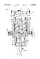
- the housing 12includes a boss 34 which defines therein a stepped bore 36.
- a sealing member 40In this stepped bore 36 at an upper larger diameter portion 38 thereof are received a sealing member 40 and a next adjacent upper bearing member 42.
- the bearing member 42rests upon an upwardly disposed shoulder 44 formed on the bore 36 by cooperation of the portion 38 thereof with a smaller diameter bore portion 46.
- This smaller diameter bore portion 46also cooperates with a lower larger diameter portion 48 of the bore 36 to define a downwardly disposed shoulder 50.
- a second bearing member 52is disposed in engagement with the shoulder 50.
- the wall portion 20 and shoulder 26are omitted to provide a better view of the rotor member 54 in the chamber 32.
- the inner diameter 84 of the conical entrance recess 80is slightly larger in diameter than the cylindrical portion 74 of core member 70, and is about coextensive with the upper end of this conical core portion, to define a radial clearance 86.
- the conical portion 72 of the core member 70extends out of the recess 80 toward the inlet port 14 so that upon liquid flow approaching the rotor member 54, the cross sectional flow area of flow path is first gradually decreased by the conical portion 72 of the core member 70, and then is additionally gradually reduced as the liquid flow enters into the conical entrance recess 80.
Landscapes
- Health & Medical Sciences (AREA)
- Engineering & Computer Science (AREA)
- Heart & Thoracic Surgery (AREA)
- Cardiology (AREA)
- Mechanical Engineering (AREA)
- Life Sciences & Earth Sciences (AREA)
- Biomedical Technology (AREA)
- Hematology (AREA)
- Anesthesiology (AREA)
- Animal Behavior & Ethology (AREA)
- General Health & Medical Sciences (AREA)
- Public Health (AREA)
- Veterinary Medicine (AREA)
- Medical Informatics (AREA)
- Pulmonology (AREA)
- Emergency Medicine (AREA)
- General Engineering & Computer Science (AREA)
- External Artificial Organs (AREA)
Abstract
Description
Claims (32)
Priority Applications (6)
| Application Number | Priority Date | Filing Date | Title |
|---|---|---|---|
| US08/083,405US5368438A (en) | 1993-06-28 | 1993-06-28 | Blood pump |
| CA002162032ACA2162032C (en) | 1993-06-28 | 1994-06-28 | Blood pump |
| PCT/US1994/007305WO1995000186A1 (en) | 1993-06-28 | 1994-06-28 | Blood pump |
| EP94922042AEP0706403B1 (en) | 1993-06-28 | 1994-06-28 | Blood pump |
| DE69431204TDE69431204T2 (en) | 1993-06-28 | 1994-06-28 | BLOOD PUMP |
| US08/336,964US5501574A (en) | 1993-06-28 | 1994-11-10 | Blood pump |
Applications Claiming Priority (1)
| Application Number | Priority Date | Filing Date | Title |
|---|---|---|---|
| US08/083,405US5368438A (en) | 1993-06-28 | 1993-06-28 | Blood pump |
Related Child Applications (1)
| Application Number | Title | Priority Date | Filing Date |
|---|---|---|---|
| US08/336,964ContinuationUS5501574A (en) | 1993-06-28 | 1994-11-10 | Blood pump |
Publications (1)
| Publication Number | Publication Date |
|---|---|
| US5368438Atrue US5368438A (en) | 1994-11-29 |
Family
ID=22178092
Family Applications (2)
| Application Number | Title | Priority Date | Filing Date |
|---|---|---|---|
| US08/083,405Expired - Fee RelatedUS5368438A (en) | 1993-06-28 | 1993-06-28 | Blood pump |
| US08/336,964Expired - Fee RelatedUS5501574A (en) | 1993-06-28 | 1994-11-10 | Blood pump |
Family Applications After (1)
| Application Number | Title | Priority Date | Filing Date |
|---|---|---|---|
| US08/336,964Expired - Fee RelatedUS5501574A (en) | 1993-06-28 | 1994-11-10 | Blood pump |
Country Status (5)
| Country | Link |
|---|---|
| US (2) | US5368438A (en) |
| EP (1) | EP0706403B1 (en) |
| CA (1) | CA2162032C (en) |
| DE (1) | DE69431204T2 (en) |
| WO (1) | WO1995000186A1 (en) |
Cited By (28)
| Publication number | Priority date | Publication date | Assignee | Title |
|---|---|---|---|---|
| US5501574A (en)* | 1993-06-28 | 1996-03-26 | Baxter International Inc. | Blood pump |
| US5527159A (en)* | 1993-11-10 | 1996-06-18 | The United States Of America As Represented By The Administrator Of The National Aeronautics And Space Administration | Rotary blood pump |
| US5770149A (en)* | 1995-10-31 | 1998-06-23 | Baxter International | Extracorporeal blood oxygenation system having integrated blood pump, heat exchanger and membrane oxygenator |
| US5947892A (en)* | 1993-11-10 | 1999-09-07 | Micromed Technology, Inc. | Rotary blood pump |
| US6123725A (en)* | 1997-07-11 | 2000-09-26 | A-Med Systems, Inc. | Single port cardiac support apparatus |
| US6254359B1 (en)* | 1996-05-10 | 2001-07-03 | The United States Of America As Represented By The Administrator Of The National Aeronautics And Space Administration | Method for providing a jewel bearing for supporting a pump rotor shaft |
| US7182727B2 (en) | 1997-07-11 | 2007-02-27 | A—Med Systems Inc. | Single port cardiac support apparatus |
| US20100123315A1 (en)* | 2008-11-20 | 2010-05-20 | Anderson Jr Winfield Scott | Tapered helical auger turbine to convert hydrokinetic energy into electrical energy |
| US20100145133A1 (en)* | 1997-10-09 | 2010-06-10 | Thoratec Corporation | Implantable heart assist system and method of applying same |
| US20110085907A1 (en)* | 2008-11-20 | 2011-04-14 | Winfield Scott Anderson | Tapered helical auger turbine to convert hydrokinetic energy into electrical energy |
| US7976271B2 (en) | 2006-01-13 | 2011-07-12 | Heartware, Inc. | Stabilizing drive for contactless rotary blood pump impeller |
| FR2963813A1 (en)* | 2010-08-13 | 2012-02-17 | Carpyz | TURBO-ECOPES TURBINE |
| US8282352B2 (en) | 2008-11-20 | 2012-10-09 | Anderson Jr Winfield Scott | Tapered helical auger turbine to convert hydrokinetic energy into electrical energy |
| US8672611B2 (en) | 2006-01-13 | 2014-03-18 | Heartware, Inc. | Stabilizing drive for contactless rotary blood pump impeller |
| CN103977464A (en)* | 2014-06-06 | 2014-08-13 | 清华大学 | Implantable miniature axial blood pump with gradually-changing flow zone at outlet |
| US20170260963A1 (en)* | 2014-11-26 | 2017-09-14 | Sang Kyu SUN | Spiral blade having wind guide |
| FR3071283A1 (en)* | 2017-09-21 | 2019-03-22 | Fineheart | CARDIAC PUMP EQUIPPED WITH INTERNAL BLADE TURBINE |
| FR3071282A1 (en)* | 2017-09-21 | 2019-03-22 | Fineheart | INTERNAL BLADE TURBINE |
| US10371151B2 (en)* | 2014-01-12 | 2019-08-06 | Alfa Corporate Ab | Self-priming centrifugal pump |
| US10422337B2 (en) | 2014-01-12 | 2019-09-24 | Alfa Laval Corporate Ab | Self-priming centrifugal pump |
| CN111770765A (en)* | 2018-01-08 | 2020-10-13 | 韦德威申思有限公司 | heart assist device |
| US11235138B2 (en) | 2015-09-25 | 2022-02-01 | Procyrion, Inc. | Non-occluding intravascular blood pump providing reduced hemolysis |
| US11241569B2 (en) | 2004-08-13 | 2022-02-08 | Procyrion, Inc. | Method and apparatus for long-term assisting a left ventricle to pump blood |
| CN114367034A (en)* | 2022-01-22 | 2022-04-19 | 上海炫脉医疗科技有限公司 | Axial-flow type blood pump with integrated impeller structure |
| US11324940B2 (en) | 2019-12-03 | 2022-05-10 | Procyrion, Inc. | Blood pumps |
| US11351359B2 (en) | 2019-12-13 | 2022-06-07 | Procyrion, Inc. | Support structures for intravascular blood pumps |
| US20220296852A1 (en)* | 2019-10-04 | 2022-09-22 | Puzzle Medical Devices Inc. | Mammalian body implantable fluid flow influencing device |
| US20220356885A1 (en)* | 2019-06-28 | 2022-11-10 | Dajustco Ip Holdings Inc. | Inducer for a submersible pump for pumping a slurry containing solids and viscous fluids and method of designing same |
Families Citing this family (43)
| Publication number | Priority date | Publication date | Assignee | Title |
|---|---|---|---|---|
| SE501215C2 (en)* | 1992-09-02 | 1994-12-12 | Oeyvind Reitan | catheter Pump |
| US5643215A (en)* | 1995-02-24 | 1997-07-01 | The Research Foundation Of State University Of New York | Gas exchange apparatus and method |
| US6162017A (en)* | 1999-04-14 | 2000-12-19 | Cardiovascular Innovations Llc | Blood pump |
| JP2001207988A (en)* | 2000-01-26 | 2001-08-03 | Nipro Corp | Magnetic driving type axial flow pump |
| US8419609B2 (en) | 2005-10-05 | 2013-04-16 | Heartware Inc. | Impeller for a rotary ventricular assist device |
| US7972122B2 (en)* | 2005-04-29 | 2011-07-05 | Heartware, Inc. | Multiple rotor, wide blade, axial flow pump |
| US7878967B1 (en)* | 2005-10-06 | 2011-02-01 | Sanjaya Khanal | Heart failure/hemodynamic device |
| ES1063777Y (en) | 2006-09-18 | 2007-03-01 | Uriarte Genaro Arana | PERFECTED CONVECTION RADIATOR |
| AU2008219653B2 (en) | 2007-02-26 | 2014-01-16 | Heartware, Inc. | Intravascular ventricular assist device |
| US20090204078A1 (en)* | 2008-02-13 | 2009-08-13 | Boston Scientific Scimed, Inc. | Manifold and Valve Seal for Use with a Medical Device |
| EP2341956B1 (en) | 2008-10-06 | 2015-12-23 | Indiana University Research and Technology Corporation | Methods and apparatus for active or passive assistance in the circulatory system |
| EP2194278A1 (en) | 2008-12-05 | 2010-06-09 | ECP Entwicklungsgesellschaft mbH | Fluid pump with a rotor |
| EP2216059A1 (en) | 2009-02-04 | 2010-08-11 | ECP Entwicklungsgesellschaft mbH | Catheter device with a catheter and an actuation device |
| EP2229965A1 (en) | 2009-03-18 | 2010-09-22 | ECP Entwicklungsgesellschaft mbH | Fluid pump with particular form of a rotor blade |
| EP2246078A1 (en) | 2009-04-29 | 2010-11-03 | ECP Entwicklungsgesellschaft mbH | Shaft assembly with a shaft which moves within a fluid-filled casing |
| EP2248544A1 (en) | 2009-05-05 | 2010-11-10 | ECP Entwicklungsgesellschaft mbH | Fluid pump with variable circumference, particularly for medical use |
| EP2266640A1 (en) | 2009-06-25 | 2010-12-29 | ECP Entwicklungsgesellschaft mbH | Compressible and expandable turbine blade for a fluid pump |
| EP2282070B1 (en) | 2009-08-06 | 2012-10-17 | ECP Entwicklungsgesellschaft mbH | Catheter device with a coupling device for a drive device |
| EP2299119B1 (en) | 2009-09-22 | 2018-11-07 | ECP Entwicklungsgesellschaft mbH | Inflatable rotor for a fluid pump |
| EP2298372A1 (en) | 2009-09-22 | 2011-03-23 | ECP Entwicklungsgesellschaft mbH | Rotor for an axial pump for transporting a fluid |
| EP2298373A1 (en) | 2009-09-22 | 2011-03-23 | ECP Entwicklungsgesellschaft mbH | Fluid pump with at least one turbine blade and a seating device |
| EP2298371A1 (en) | 2009-09-22 | 2011-03-23 | ECP Entwicklungsgesellschaft mbH | Function element, in particular fluid pump with a housing and a transport element |
| EP2314330A1 (en) | 2009-10-23 | 2011-04-27 | ECP Entwicklungsgesellschaft mbH | Flexible shaft arrangement |
| EP2314331B1 (en) | 2009-10-23 | 2013-12-11 | ECP Entwicklungsgesellschaft mbH | Catheter pump arrangement and flexible shaft arrangement with a cable core |
| EP2338540A1 (en) | 2009-12-23 | 2011-06-29 | ECP Entwicklungsgesellschaft mbH | Delivery blade for a compressible rotor |
| EP2338539A1 (en) | 2009-12-23 | 2011-06-29 | ECP Entwicklungsgesellschaft mbH | Pump device with a detection device |
| EP2338541A1 (en) | 2009-12-23 | 2011-06-29 | ECP Entwicklungsgesellschaft mbH | Radial compressible and expandable rotor for a fluid pump |
| EP2347778A1 (en) | 2010-01-25 | 2011-07-27 | ECP Entwicklungsgesellschaft mbH | Fluid pump with a radially compressible rotor |
| EP2363157A1 (en) | 2010-03-05 | 2011-09-07 | ECP Entwicklungsgesellschaft mbH | Device for exerting mechanical force on a medium, in particular fluid pump |
| EP2388029A1 (en) | 2010-05-17 | 2011-11-23 | ECP Entwicklungsgesellschaft mbH | Pump array |
| EP2399639A1 (en) | 2010-06-25 | 2011-12-28 | ECP Entwicklungsgesellschaft mbH | System for introducing a pump |
| EP2407187A3 (en) | 2010-07-15 | 2012-06-20 | ECP Entwicklungsgesellschaft mbH | Blood pump for invasive application within the body of a patient |
| EP2407185A1 (en) | 2010-07-15 | 2012-01-18 | ECP Entwicklungsgesellschaft mbH | Radial compressible and expandable rotor for a pump with a turbine blade |
| EP2407186A1 (en) | 2010-07-15 | 2012-01-18 | ECP Entwicklungsgesellschaft mbH | Rotor for a pump, produced with an initial elastic material |
| EP2422735A1 (en) | 2010-08-27 | 2012-02-29 | ECP Entwicklungsgesellschaft mbH | Implantable blood transportation device, manipulation device and coupling device |
| US20120227940A1 (en)* | 2011-03-08 | 2012-09-13 | Novel Concepts, Inc. | Toroidal Fluid Mover and Associated Heat Sink |
| EP2497521A1 (en) | 2011-03-10 | 2012-09-12 | ECP Entwicklungsgesellschaft mbH | Push device for axial insertion of a string-shaped, flexible body |
| EP2564771A1 (en) | 2011-09-05 | 2013-03-06 | ECP Entwicklungsgesellschaft mbH | Medicinal product with a functional element for invasive use in the body of a patient |
| US8926492B2 (en) | 2011-10-11 | 2015-01-06 | Ecp Entwicklungsgesellschaft Mbh | Housing for a functional element |
| US10197038B2 (en)* | 2015-09-18 | 2019-02-05 | Charles B. Culpepper | Helical longitudinal blade turbine system including a funnel throat valve comprising a plurality of semi-circular valve plates |
| US9759179B2 (en)* | 2015-09-18 | 2017-09-12 | Charles B. Culpepper | Hydroelectric generator system including helical longitudinal blades forming an open bore and aligned with a current direction |
| CN107143527B (en)* | 2017-06-06 | 2023-09-08 | 湖南司诺精密机械有限公司 | Multistage pre-rotation micro screw pump and working flow thereof |
| DE102018104405A1 (en) | 2018-02-27 | 2019-08-29 | Zcc Cutting Tools Europe Gmbh | Cutting insert for machining |
Citations (28)
| Publication number | Priority date | Publication date | Assignee | Title |
|---|---|---|---|---|
| US307275A (en)* | 1884-10-28 | edmondson | ||
| US1226278A (en)* | 1914-05-22 | 1917-05-15 | Frederick E Teves | Salt-shaker pulverizer. |
| FR1118405A (en)* | 1953-09-30 | 1956-06-06 | A Marrel Ets | Improvements to seals for hydraulic cylinders and the like |
| US2984189A (en)* | 1958-08-07 | 1961-05-16 | Worthington Corp | Inducer for a rotating pump |
| US3087435A (en)* | 1961-03-31 | 1963-04-30 | Du Pont | Pumping process |
| US3381801A (en)* | 1965-05-20 | 1968-05-07 | Rastoin Blaise | Flexible conveyor |
| US3647324A (en)* | 1969-12-18 | 1972-03-07 | Edson Howard Rafferty | Electrically driven pumps capable of use as heart pumps |
| GB1368095A (en)* | 1972-05-26 | 1974-09-25 | Filtness O T F | Rotary impeller for fluids or a propeller |
| GB1375287A (en)* | 1971-02-17 | 1974-11-27 | ||
| US3864055A (en)* | 1971-12-06 | 1975-02-04 | Harold D Kletschka | Pumps capable of use as heart pumps and blood pumps |
| GB1390741A (en)* | 1972-03-20 | 1975-04-16 | Tec Group | Axial flow device or unit for pumping or marine propulsion |
| US3918831A (en)* | 1974-02-08 | 1975-11-11 | Chandler Evans Inc | Centrifugal pump with variable impeller |
| USRE28742E (en)* | 1967-10-26 | 1976-03-23 | Pumps capable of use as heart pumps | |
| US3957389A (en)* | 1967-10-26 | 1976-05-18 | Bio-Medicus, Inc. | Pumping apparatus and process characterized by gentle operation |
| US3970408A (en)* | 1967-10-26 | 1976-07-20 | Bio-Medicus, Inc. | Apparatus for use with delicate fluids |
| US4037984A (en)* | 1967-10-26 | 1977-07-26 | Bio-Medicus, Inc. | Pumping apparatus and process characterized by gentle operation |
| WO1982003176A1 (en)* | 1981-03-18 | 1982-09-30 | Bramm Guenter Walter Otto | Megnetically suspended and rotated impellor pump apparatus and method |
| US4449895A (en)* | 1980-12-23 | 1984-05-22 | Matsushita Reiki Co., Ltd. | Refrigerant compressor |
| US4456437A (en)* | 1980-12-22 | 1984-06-26 | Matsushita Reiki Co., Ltd. | Refrigerant compressor |
| WO1985001432A1 (en)* | 1983-09-28 | 1985-04-11 | Nimbus, Inc. | High-capacity intravascular blood pump utilizing percutaneous access |
| EP0317687A1 (en)* | 1987-11-26 | 1989-05-31 | Cryomec AG | Centrifugal pump for cryogenic fluids |
| WO1989004645A1 (en)* | 1987-11-24 | 1989-06-01 | Nimbus Medical, Inc. | Percutaneous blood pump with mixed-flow output |
| US4846152A (en)* | 1987-11-24 | 1989-07-11 | Nimbus Medical, Inc. | Single-stage axial flow blood pump |
| WO1990001347A1 (en)* | 1988-08-08 | 1990-02-22 | Nimbus Medical, Inc. | Chronic ventricular assist system |
| EP0364293A2 (en)* | 1988-10-13 | 1990-04-18 | Kensey Nash Corporation | Blood pumping catheter |
| GB2239675A (en)* | 1989-12-05 | 1991-07-10 | Man Fai Shiu | Pump for pumping liquid |
| US5040944A (en)* | 1989-09-11 | 1991-08-20 | Cook Einar P | Pump having impeller rotational about convoluted stationary member |
| US5139391A (en)* | 1988-03-24 | 1992-08-18 | Pierre Carrouset | Rotary machine with non-positive displacement usable as a pump, compressor, propulsor, generator or drive turbine |
Family Cites Families (4)
| Publication number | Priority date | Publication date | Assignee | Title |
|---|---|---|---|---|
| US4877368A (en)* | 1988-11-08 | 1989-10-31 | A. Ahlstrom Corporation | Fluidizing centrifugal pump |
| US5049134A (en)* | 1989-05-08 | 1991-09-17 | The Cleveland Clinic Foundation | Sealless heart pump |
| JP2649131B2 (en)* | 1992-11-18 | 1997-09-03 | 神鋼パンテツク株式会社 | Stirrer and bottom ribbon blade used for it |
| US5368438A (en)* | 1993-06-28 | 1994-11-29 | Baxter International Inc. | Blood pump |
- 1993
- 1993-06-28USUS08/083,405patent/US5368438A/ennot_activeExpired - Fee Related
- 1994
- 1994-06-28WOPCT/US1994/007305patent/WO1995000186A1/enactiveIP Right Grant
- 1994-06-28DEDE69431204Tpatent/DE69431204T2/ennot_activeExpired - Fee Related
- 1994-06-28EPEP94922042Apatent/EP0706403B1/ennot_activeExpired - Lifetime
- 1994-06-28CACA002162032Apatent/CA2162032C/ennot_activeExpired - Fee Related
- 1994-11-10USUS08/336,964patent/US5501574A/ennot_activeExpired - Fee Related
Patent Citations (30)
| Publication number | Priority date | Publication date | Assignee | Title |
|---|---|---|---|---|
| US307275A (en)* | 1884-10-28 | edmondson | ||
| US1226278A (en)* | 1914-05-22 | 1917-05-15 | Frederick E Teves | Salt-shaker pulverizer. |
| FR1118405A (en)* | 1953-09-30 | 1956-06-06 | A Marrel Ets | Improvements to seals for hydraulic cylinders and the like |
| US2984189A (en)* | 1958-08-07 | 1961-05-16 | Worthington Corp | Inducer for a rotating pump |
| US3087435A (en)* | 1961-03-31 | 1963-04-30 | Du Pont | Pumping process |
| US3381801A (en)* | 1965-05-20 | 1968-05-07 | Rastoin Blaise | Flexible conveyor |
| US4037984A (en)* | 1967-10-26 | 1977-07-26 | Bio-Medicus, Inc. | Pumping apparatus and process characterized by gentle operation |
| US3970408A (en)* | 1967-10-26 | 1976-07-20 | Bio-Medicus, Inc. | Apparatus for use with delicate fluids |
| US3957389A (en)* | 1967-10-26 | 1976-05-18 | Bio-Medicus, Inc. | Pumping apparatus and process characterized by gentle operation |
| USRE28742E (en)* | 1967-10-26 | 1976-03-23 | Pumps capable of use as heart pumps | |
| US3647324A (en)* | 1969-12-18 | 1972-03-07 | Edson Howard Rafferty | Electrically driven pumps capable of use as heart pumps |
| GB1375287A (en)* | 1971-02-17 | 1974-11-27 | ||
| US3864055A (en)* | 1971-12-06 | 1975-02-04 | Harold D Kletschka | Pumps capable of use as heart pumps and blood pumps |
| GB1390741A (en)* | 1972-03-20 | 1975-04-16 | Tec Group | Axial flow device or unit for pumping or marine propulsion |
| GB1368095A (en)* | 1972-05-26 | 1974-09-25 | Filtness O T F | Rotary impeller for fluids or a propeller |
| US3918831A (en)* | 1974-02-08 | 1975-11-11 | Chandler Evans Inc | Centrifugal pump with variable impeller |
| US4456437A (en)* | 1980-12-22 | 1984-06-26 | Matsushita Reiki Co., Ltd. | Refrigerant compressor |
| US4449895A (en)* | 1980-12-23 | 1984-05-22 | Matsushita Reiki Co., Ltd. | Refrigerant compressor |
| EP0378251A2 (en)* | 1981-03-18 | 1990-07-18 | Günther Walter Otto Bramm | Magnetically suspended and rotated impellor pump apparatus |
| WO1982003176A1 (en)* | 1981-03-18 | 1982-09-30 | Bramm Guenter Walter Otto | Megnetically suspended and rotated impellor pump apparatus and method |
| WO1985001432A1 (en)* | 1983-09-28 | 1985-04-11 | Nimbus, Inc. | High-capacity intravascular blood pump utilizing percutaneous access |
| US4625712A (en)* | 1983-09-28 | 1986-12-02 | Nimbus, Inc. | High-capacity intravascular blood pump utilizing percutaneous access |
| WO1989004645A1 (en)* | 1987-11-24 | 1989-06-01 | Nimbus Medical, Inc. | Percutaneous blood pump with mixed-flow output |
| US4846152A (en)* | 1987-11-24 | 1989-07-11 | Nimbus Medical, Inc. | Single-stage axial flow blood pump |
| EP0317687A1 (en)* | 1987-11-26 | 1989-05-31 | Cryomec AG | Centrifugal pump for cryogenic fluids |
| US5139391A (en)* | 1988-03-24 | 1992-08-18 | Pierre Carrouset | Rotary machine with non-positive displacement usable as a pump, compressor, propulsor, generator or drive turbine |
| WO1990001347A1 (en)* | 1988-08-08 | 1990-02-22 | Nimbus Medical, Inc. | Chronic ventricular assist system |
| EP0364293A2 (en)* | 1988-10-13 | 1990-04-18 | Kensey Nash Corporation | Blood pumping catheter |
| US5040944A (en)* | 1989-09-11 | 1991-08-20 | Cook Einar P | Pump having impeller rotational about convoluted stationary member |
| GB2239675A (en)* | 1989-12-05 | 1991-07-10 | Man Fai Shiu | Pump for pumping liquid |
Cited By (67)
| Publication number | Priority date | Publication date | Assignee | Title |
|---|---|---|---|---|
| US5501574A (en)* | 1993-06-28 | 1996-03-26 | Baxter International Inc. | Blood pump |
| US5527159A (en)* | 1993-11-10 | 1996-06-18 | The United States Of America As Represented By The Administrator Of The National Aeronautics And Space Administration | Rotary blood pump |
| US5678306A (en)* | 1993-11-10 | 1997-10-21 | The United States Of America As Represented By The Administrator Of The National Aeronautics And Space Administration | Method for reducing pumping damage to blood |
| US5947892A (en)* | 1993-11-10 | 1999-09-07 | Micromed Technology, Inc. | Rotary blood pump |
| US5770149A (en)* | 1995-10-31 | 1998-06-23 | Baxter International | Extracorporeal blood oxygenation system having integrated blood pump, heat exchanger and membrane oxygenator |
| US6254359B1 (en)* | 1996-05-10 | 2001-07-03 | The United States Of America As Represented By The Administrator Of The National Aeronautics And Space Administration | Method for providing a jewel bearing for supporting a pump rotor shaft |
| US6976996B1 (en) | 1997-07-11 | 2005-12-20 | A-Med Systems, Inc. | Transport pump and organ stabilization apparatus including related methods |
| US6858001B1 (en) | 1997-07-11 | 2005-02-22 | A-Med Systems, Inc. | Single port cardiac support apparatus |
| US7182727B2 (en) | 1997-07-11 | 2007-02-27 | A—Med Systems Inc. | Single port cardiac support apparatus |
| US6123725A (en)* | 1997-07-11 | 2000-09-26 | A-Med Systems, Inc. | Single port cardiac support apparatus |
| US7998054B2 (en)* | 1997-10-09 | 2011-08-16 | Thoratec Corporation | Implantable heart assist system and method of applying same |
| US20100145133A1 (en)* | 1997-10-09 | 2010-06-10 | Thoratec Corporation | Implantable heart assist system and method of applying same |
| US8900115B2 (en) | 1997-10-09 | 2014-12-02 | Thoratec Corporation | Implantable heart assist system and method of applying same |
| US7993260B2 (en)* | 1997-10-09 | 2011-08-09 | Thoratec Corporation | Implantable heart assist system and method of applying same |
| US11241569B2 (en) | 2004-08-13 | 2022-02-08 | Procyrion, Inc. | Method and apparatus for long-term assisting a left ventricle to pump blood |
| US11642511B2 (en) | 2004-08-13 | 2023-05-09 | Procyrion, Inc. | Method and apparatus for long-term assisting a left ventricle to pump blood |
| US9050405B2 (en) | 2006-01-13 | 2015-06-09 | Heartware, Inc. | Stabilizing drive for contactless rotary blood pump impeller |
| US10731652B2 (en) | 2006-01-13 | 2020-08-04 | Heartware, Inc. | Hydrodynamic thrust bearings for rotary blood pump |
| US9777732B2 (en) | 2006-01-13 | 2017-10-03 | Heartware, Inc. | Hydrodynamic thrust bearings for rotary blood pump |
| US9242032B2 (en) | 2006-01-13 | 2016-01-26 | Heartware, Inc. | Rotary pump with thrust bearings |
| US7997854B2 (en) | 2006-01-13 | 2011-08-16 | Heartware, Inc. | Shrouded thrust bearings |
| US8512013B2 (en) | 2006-01-13 | 2013-08-20 | Heartware, Inc. | Hydrodynamic thrust bearings for rotary blood pumps |
| US8540477B2 (en) | 2006-01-13 | 2013-09-24 | Heartware, Inc. | Rotary pump with thrust bearings |
| US8672611B2 (en) | 2006-01-13 | 2014-03-18 | Heartware, Inc. | Stabilizing drive for contactless rotary blood pump impeller |
| US8932006B2 (en) | 2006-01-13 | 2015-01-13 | Heartware, Inc. | Rotary pump with thrust bearings |
| US7976271B2 (en) | 2006-01-13 | 2011-07-12 | Heartware, Inc. | Stabilizing drive for contactless rotary blood pump impeller |
| US20110085907A1 (en)* | 2008-11-20 | 2011-04-14 | Winfield Scott Anderson | Tapered helical auger turbine to convert hydrokinetic energy into electrical energy |
| US8282352B2 (en) | 2008-11-20 | 2012-10-09 | Anderson Jr Winfield Scott | Tapered helical auger turbine to convert hydrokinetic energy into electrical energy |
| US8152464B2 (en) | 2008-11-20 | 2012-04-10 | Anderson Jr Winfield Scott | Tapered helical auger turbine to convert hydrokinetic energy into electrical energy |
| US20100123315A1 (en)* | 2008-11-20 | 2010-05-20 | Anderson Jr Winfield Scott | Tapered helical auger turbine to convert hydrokinetic energy into electrical energy |
| US7728454B1 (en)* | 2008-11-20 | 2010-06-01 | Anderson Jr Winfield Scott | Tapered helical auger turbine to convert hydrokinetic energy into electrical energy |
| FR2963813A1 (en)* | 2010-08-13 | 2012-02-17 | Carpyz | TURBO-ECOPES TURBINE |
| US10371151B2 (en)* | 2014-01-12 | 2019-08-06 | Alfa Corporate Ab | Self-priming centrifugal pump |
| US10422337B2 (en) | 2014-01-12 | 2019-09-24 | Alfa Laval Corporate Ab | Self-priming centrifugal pump |
| CN103977464A (en)* | 2014-06-06 | 2014-08-13 | 清华大学 | Implantable miniature axial blood pump with gradually-changing flow zone at outlet |
| US20170260963A1 (en)* | 2014-11-26 | 2017-09-14 | Sang Kyu SUN | Spiral blade having wind guide |
| US10927808B2 (en)* | 2014-11-26 | 2021-02-23 | Sang Kyu SUN | Spiral blade having wind guide |
| US12078192B2 (en) | 2015-09-25 | 2024-09-03 | Procyrion, Inc. | Non-occluding intra vascular blood pump providing reduced hemolysis |
| US11235138B2 (en) | 2015-09-25 | 2022-02-01 | Procyrion, Inc. | Non-occluding intravascular blood pump providing reduced hemolysis |
| FR3071282A1 (en)* | 2017-09-21 | 2019-03-22 | Fineheart | INTERNAL BLADE TURBINE |
| WO2019057776A1 (en)* | 2017-09-21 | 2019-03-28 | Fineheart | Turbine with internal blades |
| CN111372618A (en)* | 2017-09-21 | 2020-07-03 | 好心公司 | Turbine with internal buckets |
| US10933180B2 (en) | 2017-09-21 | 2021-03-02 | Fineheart | Cardiac pump having a turbine with internal blades |
| US10954954B2 (en) | 2017-09-21 | 2021-03-23 | Fineheart | Turbine with internal blades |
| CN111278480A (en)* | 2017-09-21 | 2020-06-12 | 好心公司 | Cardiac pump having a turbine with internal vanes |
| WO2019057779A1 (en)* | 2017-09-21 | 2019-03-28 | Fineheart | Cardiac pump having a turbine with internal blades |
| FR3071283A1 (en)* | 2017-09-21 | 2019-03-22 | Fineheart | CARDIAC PUMP EQUIPPED WITH INTERNAL BLADE TURBINE |
| CN111770765B (en)* | 2018-01-08 | 2024-05-14 | 星辰Bp有限公司 | Heart assist devices |
| US12076546B2 (en) | 2018-01-08 | 2024-09-03 | Star Bp, Inc. | Heart assist device |
| US11724093B2 (en) | 2018-01-08 | 2023-08-15 | Vadovations, Inc. | Heart assist device |
| CN111770765A (en)* | 2018-01-08 | 2020-10-13 | 韦德威申思有限公司 | heart assist device |
| US12098728B2 (en)* | 2019-06-28 | 2024-09-24 | Dajustco Ip Holdings Inc. | Inducer for a submersible pump for pumping a slurry containing solids and viscous fluids and method of designing same |
| US20220356885A1 (en)* | 2019-06-28 | 2022-11-10 | Dajustco Ip Holdings Inc. | Inducer for a submersible pump for pumping a slurry containing solids and viscous fluids and method of designing same |
| US20220296852A1 (en)* | 2019-10-04 | 2022-09-22 | Puzzle Medical Devices Inc. | Mammalian body implantable fluid flow influencing device |
| US11857777B2 (en) | 2019-12-03 | 2024-01-02 | Procyrion, Inc. | Blood pumps |
| US11452859B2 (en) | 2019-12-03 | 2022-09-27 | Procyrion, Inc. | Blood pumps |
| US11324940B2 (en) | 2019-12-03 | 2022-05-10 | Procyrion, Inc. | Blood pumps |
| US11517736B2 (en) | 2019-12-03 | 2022-12-06 | Procyrion, Inc. | Blood pumps |
| US12161854B2 (en) | 2019-12-03 | 2024-12-10 | Procyrion, Inc. | Blood pumps |
| US11779751B2 (en) | 2019-12-03 | 2023-10-10 | Procyrion, Inc. | Blood pumps |
| US11471665B2 (en) | 2019-12-13 | 2022-10-18 | Procyrion, Inc. | Support structures for intravascular blood pumps |
| US11697017B2 (en) | 2019-12-13 | 2023-07-11 | Procyrion, Inc. | Support structures for intravascular blood pumps |
| US12017060B2 (en) | 2019-12-13 | 2024-06-25 | Procyrion, Inc. | Support structures for intravascular blood pumps |
| US11571559B2 (en) | 2019-12-13 | 2023-02-07 | Procyrion, Inc. | Support structures for intravascular blood pumps |
| US11351359B2 (en) | 2019-12-13 | 2022-06-07 | Procyrion, Inc. | Support structures for intravascular blood pumps |
| CN114367034A (en)* | 2022-01-22 | 2022-04-19 | 上海炫脉医疗科技有限公司 | Axial-flow type blood pump with integrated impeller structure |
| CN114367034B (en)* | 2022-01-22 | 2023-08-22 | 上海炫脉医疗科技有限公司 | Axial flow blood pump with integrated impeller structure |
Also Published As
| Publication number | Publication date |
|---|---|
| EP0706403A1 (en) | 1996-04-17 |
| WO1995000186A1 (en) | 1995-01-05 |
| CA2162032A1 (en) | 1995-01-05 |
| EP0706403B1 (en) | 2002-08-21 |
| CA2162032C (en) | 2002-01-29 |
| DE69431204T2 (en) | 2003-08-07 |
| DE69431204D1 (en) | 2002-09-26 |
| US5501574A (en) | 1996-03-26 |
Similar Documents
| Publication | Publication Date | Title |
|---|---|---|
| US5368438A (en) | Blood pump | |
| US5316440A (en) | Blood pump apparatus | |
| US5458459A (en) | Centrifugal blood pump with impeller blades forming a spin inducer | |
| KR102615684B1 (en) | blood pump | |
| EP1473048B1 (en) | Turbo blood pump | |
| US3864055A (en) | Pumps capable of use as heart pumps and blood pumps | |
| US5863179A (en) | Centrifugal blood pump | |
| US3647324A (en) | Electrically driven pumps capable of use as heart pumps | |
| MXPA04005067A (en) | Passive non-contacting smart bearing suspension for turbo blood-pumps. | |
| KR20230162995A (en) | Blood pump | |
| CN109821084B (en) | It is a kind of that shaftless heart pump can plant based on flow passage gradual change | |
| JP7426503B2 (en) | blood pump | |
| EP4393536A1 (en) | Blood pump | |
| CA2374656A1 (en) | Magnetic suspension blood pump | |
| EP0518050B1 (en) | Liquid pump apparatus | |
| CN116637293B (en) | Impeller, pump head and magnetic suspension ventricular assist device | |
| CN209301837U (en) | An extracorporeal blood pump capable of reducing hemolysis | |
| WO2002027225A1 (en) | Turbo blood pump with inclined impeller vanes | |
| WO1992021388A1 (en) | Pump | |
| WO1995009984A1 (en) | Centrifugal blood pump with impeller blades forming a spin inducer | |
| EP0421280A1 (en) | Precessing centrifugal pump integrally combined with a motor | |
| JP2605192B2 (en) | Blood pump | |
| CN217091799U (en) | Sealing mechanism with anti-coagulation structure and heart blood pump | |
| JP3247718B2 (en) | Blood pump | |
| JPH0984872A (en) | Eccentric type blood pump |
Legal Events
| Date | Code | Title | Description |
|---|---|---|---|
| AS | Assignment | Owner name:BAXTER INTERNATIONAL INC. Free format text:ASSIGNMENT OF ASSIGNORS INTEREST;ASSIGNOR:RAIBLE, DONALD A.;REEL/FRAME:006626/0011 Effective date:19930628 | |
| FEPP | Fee payment procedure | Free format text:PAYOR NUMBER ASSIGNED (ORIGINAL EVENT CODE: ASPN); ENTITY STATUS OF PATENT OWNER: LARGE ENTITY | |
| FEPP | Fee payment procedure | Free format text:PAYOR NUMBER ASSIGNED (ORIGINAL EVENT CODE: ASPN); ENTITY STATUS OF PATENT OWNER: LARGE ENTITY Free format text:PAYER NUMBER DE-ASSIGNED (ORIGINAL EVENT CODE: RMPN); ENTITY STATUS OF PATENT OWNER: LARGE ENTITY | |
| FPAY | Fee payment | Year of fee payment:4 | |
| AS | Assignment | Owner name:EDWARDS LIFESCIENCES CORPORATION, CALIFORNIA Free format text:ASSIGNMENT OF ASSIGNORS INTEREST;ASSIGNOR:BAXTER INTERNATIONAL INC.;REEL/FRAME:010901/0274 Effective date:20000609 | |
| AS | Assignment | Owner name:JOSTRA BENTLEY INC., PUERTO RICO Free format text:ASSIGNMENT OF ASSIGNORS INTEREST;ASSIGNOR:EDWARDS LIFESCIENCES CORPORATION;REEL/FRAME:011190/0824 Effective date:20000831 | |
| FPAY | Fee payment | Year of fee payment:8 | |
| REMI | Maintenance fee reminder mailed | ||
| LAPS | Lapse for failure to pay maintenance fees | ||
| STCH | Information on status: patent discontinuation | Free format text:PATENT EXPIRED DUE TO NONPAYMENT OF MAINTENANCE FEES UNDER 37 CFR 1.362 | |
| FP | Lapsed due to failure to pay maintenance fee | Effective date:20061129 |