US5368041A - Monitor and method for acquiring and processing electrical signals relating to bodily functions - Google Patents
Monitor and method for acquiring and processing electrical signals relating to bodily functionsDownload PDFInfo
- Publication number
- US5368041A US5368041AUS07/961,525US96152592AUS5368041AUS 5368041 AUS5368041 AUS 5368041AUS 96152592 AUS96152592 AUS 96152592AUS 5368041 AUS5368041 AUS 5368041A
- Authority
- US
- United States
- Prior art keywords
- signals
- monitor
- unfiltered
- acquiring
- data
- Prior art date
- Legal status (The legal status is an assumption and is not a legal conclusion. Google has not performed a legal analysis and makes no representation as to the accuracy of the status listed.)
- Expired - Lifetime
Links
- 238000012545processingMethods0.000titleclaimsabstractdescription42
- 238000000034methodMethods0.000titledescription13
- 230000006870functionEffects0.000titledescription5
- 238000001914filtrationMethods0.000claimsdescription16
- 210000000056organAnatomy0.000claims2
- 230000001360synchronised effectEffects0.000description11
- 238000012360testing methodMethods0.000description11
- 238000010586diagramMethods0.000description9
- 238000004891communicationMethods0.000description7
- 230000008901benefitEffects0.000description6
- 238000001514detection methodMethods0.000description6
- 238000007667floatingMethods0.000description5
- 238000006243chemical reactionMethods0.000description4
- 238000005070samplingMethods0.000description4
- 230000007704transitionEffects0.000description4
- 230000004075alterationEffects0.000description3
- 230000000694effectsEffects0.000description3
- 230000005540biological transmissionEffects0.000description2
- 210000004556brainAnatomy0.000description2
- 210000004027cellAnatomy0.000description2
- 239000013078crystalSubstances0.000description2
- 239000012528membraneSubstances0.000description2
- 230000004048modificationEffects0.000description2
- 238000012986modificationMethods0.000description2
- 238000011084recoveryMethods0.000description2
- 238000012546transferMethods0.000description2
- 238000012935AveragingMethods0.000description1
- FAPWRFPIFSIZLT-UHFFFAOYSA-MSodium chlorideChemical compound[Na+].[Cl-]FAPWRFPIFSIZLT-UHFFFAOYSA-M0.000description1
- 229940035674anestheticsDrugs0.000description1
- 230000007177brain activityEffects0.000description1
- 239000003990capacitorSubstances0.000description1
- 230000008878couplingEffects0.000description1
- 238000010168coupling processMethods0.000description1
- 238000005859coupling reactionMethods0.000description1
- 229940079593drugDrugs0.000description1
- 239000003814drugSubstances0.000description1
- 239000003193general anesthetic agentSubstances0.000description1
- 238000002847impedance measurementMethods0.000description1
- 208000028867ischemiaDiseases0.000description1
- 238000002955isolationMethods0.000description1
- 239000007788liquidSubstances0.000description1
- 238000004519manufacturing processMethods0.000description1
- 239000000463materialSubstances0.000description1
- 238000012544monitoring processMethods0.000description1
- 210000002569neuronAnatomy0.000description1
- 230000008569processEffects0.000description1
- 230000001105regulatory effectEffects0.000description1
- 238000012421spikingMethods0.000description1
- 238000009423ventilationMethods0.000description1
Images


Classifications
- A—HUMAN NECESSITIES
- A61—MEDICAL OR VETERINARY SCIENCE; HYGIENE
- A61B—DIAGNOSIS; SURGERY; IDENTIFICATION
- A61B5/00—Measuring for diagnostic purposes; Identification of persons
- A61B5/68—Arrangements of detecting, measuring or recording means, e.g. sensors, in relation to patient
- A61B5/6801—Arrangements of detecting, measuring or recording means, e.g. sensors, in relation to patient specially adapted to be attached to or worn on the body surface
- A61B5/6843—Monitoring or controlling sensor contact pressure
- A—HUMAN NECESSITIES
- A61—MEDICAL OR VETERINARY SCIENCE; HYGIENE
- A61B—DIAGNOSIS; SURGERY; IDENTIFICATION
- A61B5/00—Measuring for diagnostic purposes; Identification of persons
- A61B5/0002—Remote monitoring of patients using telemetry, e.g. transmission of vital signals via a communication network
- A61B5/0004—Remote monitoring of patients using telemetry, e.g. transmission of vital signals via a communication network characterised by the type of physiological signal transmitted
- A61B5/0006—ECG or EEG signals
- A—HUMAN NECESSITIES
- A61—MEDICAL OR VETERINARY SCIENCE; HYGIENE
- A61B—DIAGNOSIS; SURGERY; IDENTIFICATION
- A61B5/00—Measuring for diagnostic purposes; Identification of persons
- A61B5/24—Detecting, measuring or recording bioelectric or biomagnetic signals of the body or parts thereof
- A61B5/316—Modalities, i.e. specific diagnostic methods
- A61B5/369—Electroencephalography [EEG]
- A61B5/372—Analysis of electroencephalograms
- G—PHYSICS
- G16—INFORMATION AND COMMUNICATION TECHNOLOGY [ICT] SPECIALLY ADAPTED FOR SPECIFIC APPLICATION FIELDS
- G16H—HEALTHCARE INFORMATICS, i.e. INFORMATION AND COMMUNICATION TECHNOLOGY [ICT] SPECIALLY ADAPTED FOR THE HANDLING OR PROCESSING OF MEDICAL OR HEALTHCARE DATA
- G16H40/00—ICT specially adapted for the management or administration of healthcare resources or facilities; ICT specially adapted for the management or operation of medical equipment or devices
- G16H40/60—ICT specially adapted for the management or administration of healthcare resources or facilities; ICT specially adapted for the management or operation of medical equipment or devices for the operation of medical equipment or devices
- G16H40/63—ICT specially adapted for the management or administration of healthcare resources or facilities; ICT specially adapted for the management or operation of medical equipment or devices for the operation of medical equipment or devices for local operation
- G—PHYSICS
- G16—INFORMATION AND COMMUNICATION TECHNOLOGY [ICT] SPECIALLY ADAPTED FOR SPECIFIC APPLICATION FIELDS
- G16Z—INFORMATION AND COMMUNICATION TECHNOLOGY [ICT] SPECIALLY ADAPTED FOR SPECIFIC APPLICATION FIELDS, NOT OTHERWISE PROVIDED FOR
- G16Z99/00—Subject matter not provided for in other main groups of this subclass
- A—HUMAN NECESSITIES
- A61—MEDICAL OR VETERINARY SCIENCE; HYGIENE
- A61B—DIAGNOSIS; SURGERY; IDENTIFICATION
- A61B5/00—Measuring for diagnostic purposes; Identification of persons
- A61B5/72—Signal processing specially adapted for physiological signals or for diagnostic purposes
- A61B5/7203—Signal processing specially adapted for physiological signals or for diagnostic purposes for noise prevention, reduction or removal
- A61B5/7217—Signal processing specially adapted for physiological signals or for diagnostic purposes for noise prevention, reduction or removal of noise originating from a therapeutic or surgical apparatus, e.g. from a pacemaker
- Y—GENERAL TAGGING OF NEW TECHNOLOGICAL DEVELOPMENTS; GENERAL TAGGING OF CROSS-SECTIONAL TECHNOLOGIES SPANNING OVER SEVERAL SECTIONS OF THE IPC; TECHNICAL SUBJECTS COVERED BY FORMER USPC CROSS-REFERENCE ART COLLECTIONS [XRACs] AND DIGESTS
- Y10—TECHNICAL SUBJECTS COVERED BY FORMER USPC
- Y10S—TECHNICAL SUBJECTS COVERED BY FORMER USPC CROSS-REFERENCE ART COLLECTIONS [XRACs] AND DIGESTS
- Y10S128/00—Surgery
- Y10S128/901—Suppression of noise in electric signal
- Y—GENERAL TAGGING OF NEW TECHNOLOGICAL DEVELOPMENTS; GENERAL TAGGING OF CROSS-SECTIONAL TECHNOLOGIES SPANNING OVER SEVERAL SECTIONS OF THE IPC; TECHNICAL SUBJECTS COVERED BY FORMER USPC CROSS-REFERENCE ART COLLECTIONS [XRACs] AND DIGESTS
- Y10—TECHNICAL SUBJECTS COVERED BY FORMER USPC
- Y10S—TECHNICAL SUBJECTS COVERED BY FORMER USPC CROSS-REFERENCE ART COLLECTIONS [XRACs] AND DIGESTS
- Y10S128/00—Surgery
- Y10S128/902—Biological signal amplifier
Definitions
- the present inventionrelates in general to bodily electrical signal monitors, and more particularly to a monitor and method for acquiring and processing EEG data in EEG monitors.
- An EEG data signalis an acquired medical electrical signal representing brain activity.
- the EEG data signalis in the form of complex waveforms which can be broken down into a series of sine waves. The frequencies and amplitudes of each of these sine waves are analyzed to represent the bioelectrical activity of millions of neurons in the brain.
- anesthetics, neuroactive drugs, ischemia or other physiological changes in the brainare monitored by examining the EEG data.
- bispectral analysis of EEG datahas been used to derive more complete information concerning such physiological changes.
- noisemay obscure or distort the original EEG data signal.
- an EEG data signallooks to be significantly affected by noise, and very heavy filtering is commonly used to preserve the important characteristics of the EEG data signal.
- filteringis often not successful because of artifacts such as electrocautery which generate noise over a wide band including the band of interest in the EEG signals. It is frequently difficult or impossible to differentiate the artifact signal in the EEG band from the EEG itself. This can lead to a situation where the artifact is mistaken for an EEG, and possibly to a misdiagnosis.
- Another object of the present inventionis to provide a monitor for acquiring and processing EEG data that is highly impervious to electrical noise pollution in the operating room.
- the EEG monitor of the present inventionutilizes a portable data acquisition module and a substantially stationary processing module.
- the EEG signalsare acquired and converted to an oversampled stream of digital signals by a sigma-delta modulator located in the data acquisition module.
- the signalsare then filtered by a decimation filter located in the processing module. Additional means are also provided to monitor the electrode leads to detect when the leads become unplugged.
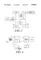
- FIG. 1is a block diagram of the EEG monitor of the present invention
- FIG. 2is a block diagram of the circuitry of the motherboard of the EEG monitor shown in FIG. 1;
- FIG. 3is a block diagram of the circuitry of one channel of the portable data acquisition module 14 of the EEG monitor shown in FIG. 1;
- FIG. 4is a block diagram of the data and power conversion circuitry for the data acquisition module of the EEG monitor shown in FIG. 1;
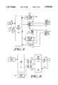
- FIG. 5is a block diagram showing the flow of EEG data signals through the EEG monitor shown in FIG. 1;
- FIG. 6is a block diagram of the sigma-delta modulator of the EEG monitor shown in FIG. 1;
- FIG. 7is a block diagram of the circuitry for detecting that the leads are off the head utilized by the EEG monitor shown in FIG. 1;
- FIG. 8is a block diagram of the front end interface of the EEG monitor shown in FIG. 1;
- FIG. 9is a block diagram of the relationship of the clock synchronization components of the EEG monitor shown in FIG. 1;
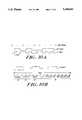
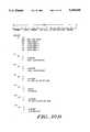
- FIG. 10Ais a bit map showing bi-phase encoding
- FIG. 10Bis a bit map of the interface protocol used by the EEG monitor shown in FIG. 1;
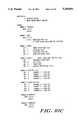
- FIG. 10Cis a chart of the status protocol used by the EEG monitor shown in FIG. 1;
- FIG. 10Dis a chart of the control protocol used by the EEG monitor shown in FIG. 1;
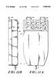
- FIG. 11Ais a front elevational view of the portable data acquisition module of the EEG monitor shown in FIG. 1;
- FIG. 11Bis a side elevational view of the portable data acquisition module of the EEG monitor shown in FIG. 1.
- the EEG monitor 10 of the present inventionincludes a stationary base processing module 12 and a portable data acquisition module 14.
- the portable data acquisition module 14contains the circuitry required to acquire the EEG data from a patient.
- the data acquisition module 14digitizes the waveforms obtained from a patient for transmission to and processing by the processing module 12.
- the data acquisition module 14is connected to the processing module 12 via a thin, highly flexible cable 15.
- the processing module 12processes EEG data, calculates variables, and displays waveforms and variables. All of the circuitry for acquiring and digitizing the EEG data, however, is located in the data acquisition module 14.
- the processing module 12includes a motherboard 16 which is shown in greater detail in FIG. 2 and which is primarily responsible for signal processing functions.
- a host CPU 18is used to control the operation of the processing module 12.
- the host CPU 18is an 80286 16 MHz CPU, connected to 1 Mbyte non-volatile DRAM on the motherboard 16, 2 serial RS-232 ports, 1 parallel port, keyboard port, speaker port, battery backed-up real time clock, hardware watchdog timer, and a PROM 130.
- the processing module 12also includes a display 20 which in a preferred embodiment is a VGA-type display to show EEG waveforms and other information and an index display 22.
- the VGA display 20is powered by display power supply 30 and controlled by display driver 32 which is connected to host CPU 118.
- the index display 22contains LEDs for displaying the processed variables in solid-state seven-segment characters. In a preferred embodiment there are three full digits with decimal points, and a leading +/-display.
- the housing for the processing modulesalso includes LED indicators for ON/STANDBY, BATTERY, LOW BATTERY, and ALARM OFF.
- a membrane switch panelis mounted in front of the processor module housing, and contains the switches for ON/STANDBY and ALARM OFF. Keys 24 interface to the index display board.
- a membrane switch panelwill also preferably contain a number of soft keys 26 and hard keys 28 for functions such as FREEZE, PRINT, HELP, and START CASE.
- a power supply 34supplies power to the entire monitor and battery 36 is provided for backup purposes.
- Motherboard 16includes a bus interface 120 to the host CPU 18.
- this bus interface 108is designed to conform with the IBM-standard AT bus specification.
- An integer digital signal processor 122 connected to the bus interface 120filters the raw EEG data and downsamples it to its final sample rate.
- the integer digital signal processor 122may also detect artifacts at frequencies both in the base band and higher than the base band.
- the integer digital signal processor 122is an Analog Devices ADSP2105 processor running at 10.245 Mhz.
- Raw EEG data signalsare transferred from the integer digital signal processor 122 to the host CPU 18 for display.
- the raw EEG waveformsare electronically displayed, as are a variety of variables which are processed from the EEG by the monitor of the present invention.
- the integer digital signal processor 122transmits raw EEG data to the floating point digital signal processor 124 at 128 words/second/channel via a serial port.
- the floating point digital signal processor 124computes all of the processed variables from the EEG data, including bispectral indices if desired.
- the floating point digital signal processor 124is a Texas Instruments TMS320C30 processor.
- the floating point digital signal processorruns at 33.33 MHz.
- a speaker 128is used for audible alarms.
- the hostprovides the speaker tones, while the volume is set via an I/O register on the AT bus.
- the speaker amplifier and volume controlare on the motherboard.
- the operating code for the monitoris preferably located in programmable read-only memory 130 on a board that is accessible from the rear of the stationary processing module 12, allowing software changes to be made without dismantling the processing module 12.
- the EPROM 130is interfaced to the AT bus 132.
- the boardcan accept either 1 or 2 Mbytes of PROM.
- the external I/O connectors for the processing module 12are mounted on the motherboard 16.
- the motherboard 16occupies the full depth of the processing module 12.
- circuitry for one of the four channels of the portable data acquisition module 14will now be described.
- the circuitry for the other three channels of the data acquisition module 14is substantially identical to the circuitry shown in FIG. 3.
- data acquisition module 14has connections 40 for ten electrodes. Eight of the electrodes are used as bipolar inputs for the four EEG data channels.
- the EEG data channelscan be operated as either bipolar or referential, and one of the electrodes is used as a positive reference when the data channels are being operated in referential mode.
- the last electrodeis used as an electrical ground for the patient and the portable data acquisition module 14.
- Two electrode input jacks 44, 46are shown for the first data channel. In the preferred embodiment, unused inputs are shorted externally, but they could be software controlled as well.
- An input protection circuit 48protects the data acquisition module 14 from damage resulting from electric shock from low capacity sources such as people.
- the module 14is designed to survive a defibrillator pulse to the patient.
- Input protection circuit 48also reduces the effects from high frequency ambient noise from sources such as electrocautery and other devices found in the operating room.
- montage mode switch 50For each of the four data channels there is there a montage mode switch 50, differential amplifiers 56, DC servo 58, impedance test circuit 54, and lead off detection circuits 52. There are circuits for injecting self-test voltages into the amplifier inputs. Portions of the self test circuits are on the preamp board 40 as well. The inputs to all four EEG data channels can simultaneously be zeroed on command from the host.
- Impedance testing of the electrodesis under control of the host CPU 18. This is done by injecting a current of less than 0.2 ⁇ A (per AAMI standard for ECG) into each electrode at a frequency within the normal EEG bandwidth and measuring the resulting voltages. A sinusoidal current source is switched into each electrode while a digital signal processor measures the resulting voltage. The host CPU 18 controls the electrode switching. All the positive electrode leads are tested at the same time, and then all the negative electrode leads are tested. The impedance measurement range is 0-25 Kohms. The ground electrode impedance is not measured. The impedance test results enable the EEG technician to match the impedance of the electrodes and to achieve the best noise and common mode rejection performance.
- the EEG data signalsare amplified by a full instrumentation amplifier 56 which has a fixed gain.
- Each amplifierhas a DC servo 58 which removes all signals below a high pass cutoff frequency.
- the servos 58can be changed to a higher frequency to facilitate fast recovery. Recovery is performed under control of the host processor 18.
- the hostsets the amplifier mode to either bipolar or referential upon a request by an operator through a control on the processing module housing.
- Light emitting diodes, located in the preferred embodiment, on the preamp board 40 of data acquisition module 14indicate the mode currently in use.
- the communications board 60 on portable data acquisition module 14contains an amplifier/filter circuit 62 and a sigma-delta modulator 64 for each EEG data channel.
- the communications board 60also contains interface multiplexer 66 (which in a preferred embodiment is a programmable logic device), power supply circuits 68, self-test circuit 70 for producing the test tone, and a comparator for the lead off detector 52.
- a crystal controlled portable data acquisition module master clock 67drives the modulators 64 and the interface at a divided rate through the PLD 66.
- Each EEG data channelis amplified by an amplifier/filter circuit 62 to the level required by the analog to digital modulator 64, as will be described in greater detail below in connection with FIG. 6.
- Amplifier 62also serves as a filter to prevent aliasing by the modulator 64.
- the filter 24is of the third order, and is set to a frequency well above the required EEG bandwidth. This preserves the linear phase of the signal and enables the detection of artifacts over a wide bandwidth.
- sigma-delta modulator 64runs at 16384 Hz, and is also of third order. This permits the final decimated sample rate of 128 Hz to yield better than 14 bit signal to noise ratio performance, which is more than acceptable for the EEG.
- a calibrated test signalis generated on the communications board 60 by self-test generator 70 under command from the host processor 18 on the processor module 12.
- the signal 71is a 2 Hz square wave of +/-100uV. It is applied to the inputs of the differential amplifiers 56, where it drives the gain ports of amplifiers 56, resulting in a test of the entire signal path except for the input jacks 44, 46, protection circuits 22 and lead switches 50.
- the interface from the data acquisition module 14 to the processing module 12is comprised of a data-out serial line 80 and a control-in serial line 82.
- the outputs from each of the four EEG data channels 84, 86, 88, 90are multiplexed in interface mulitplexer 66, which as described above is a programmable logic device.
- Status informationsuch module identification, mode (bipolar or referential), lead off indication, and power supply faults is multiplexed with the EEG data.
- the status informationis transmitted only on command from the processing module 12.
- the output from the interface mulitplexer 66is transformer-coupled onto a balanced, twisted pair line.
- the transformers 72, 74provide the required patient isolation from ground.
- One twisted-pair signalwhich provides the control data, also transmits power from the processing module 12 to the data acquisition module 14.
- the data on the control-in line 82 and the data-out line 80is bi-phase encoded.
- the signalsmay be transmitted optically or through a wireless (e.g., radio) connection.
- the control-in lineis driven by the front end driver 244 (see FIG. 8).
- the drive signalis balanced, and output levels are 0 to 12 volts peak to peak.
- the signalsAfter passing through a shielded twisted pair line 82, the signals are coupled onto the communications board 60 by means of a transformer 74 (see FIG. 4).
- the signalsare passed onto the control data receiver 116 which converts them to TTL levels before sending them to the decoder PLD 66.
- the communications board 60decodes the control information coming from the processing module 12 via control-in line 82. Commands such as "auto-recover from amplifier saturation" and "conduct impedance tests" are transmitted by the host CPU 18 to the communications board 60.
- the control-in data rateis synchronized to the EEG data-out rate by a phase-locked loop (as described in greater detail below in FIGS. 8 and 9) in the data processing module 12, preventing interference on the EEG data signals from the command-in line.
- the data acquisition module 14also derives power from the control-in line 82.
- the transformer coupled control-in signal 75is rectified by rectifier 112.
- the resulting DC signalis linearly regulated by regulators 114 to provide power to the data acquisition module 14 at the appropriate voltages.
- All of the circuits in the data acquisition module 14are exactly synchronized to the master clock 67, which in the preferred embodiment is a crystal controlled 2.0977152 MHz clock.
- the master clock 67clocks the communications PLD 66 in the data acquisition module 14.
- the data-out signal 80is thus synchronous with the master clock 67.
- the front end interface PLD 66arecovers the synchronized clock 300 from the data-out line 80, and feeds the recovered clock 300 to the phase locked loop 240.
- the phase locked loop 240generates a higher frequency clock 301 that is synchronized to the recovered clock 300, and is thus also synchronous with the master clock 67.
- the PLL 240sends this clock back to the front end interface PLD 66a, which uses it to clock the control-in line 82 to the data acquisition module 14.
- the data acquisition module 14uses this synchronized signal to decode control information and generate power. In this way, all of the circuits in the data acquisition module 14 operate at frequencies that are exactly synchronized with the master clock 67. This provides the advantage that signals coming back into the data acquisition module 14 will not cause interference by mixing with the clock signals already in the module 14, disturbing the sensitive EEG acquisition circuits.
- FIG. 5shows the data flow for one channel of data and the data flow for the other three channels is substantially identical.
- EEG data signals for one channelare acquired via patient connection 20.
- the other three patient connections, identical to patient connection 20,are not shown in FIG. 5.
- the EEG data signalspass through input protection circuit 48 in the data acquisition module 14. There are four input protection circuits, although only one is shown.
- Each channel of EEG datais differentially amplified by instrumentation amplifiers 56, and further amplified and filtered to remove DC and high frequency components by four separate amplifier/filter circuits 62.
- the EEG data signals for each channelare then digitized by one bit sigma-delta analog-to-digital modulators 64 connected to each channel.
- the outputs from all four modulatorsare multiplexed by multiplexer 66 for transfer from the data acquisition module 14 over cable 16 to the processing module 12 where they are demultiplexed by a demultiplexer 66a.
- the EEG data signalsare transferred to integer digital signal processor (IDSP) 122.
- the processor 122digitally filters the signals and downsamples them before transmitting them to the host CPU 18 for display 20.
- the integer digital signal processor 122concurrently filters and downsamples the signals for processing by floating point digital signal processor (FDSP) 124.
- FDSPfloating point digital signal processor
- the converter of the present inventionis comprised of a sigma-delta modulator 64 in the data acquisition module 14 and the digital signal processor 122 in the processing module 12.
- the converter of the present inventionthere are four converters, one for each data channel.
- the sigma-delta modulator 64is provided to convert the signal of interest to a digital form.
- Converters of any typecan only approximate the signal, yielding limited resolution, signal-to-noise ratio, distortion and frequency band width.
- Conventional converterstypically sample the signal at just above the Nyquist rate (two times the highest frequency of interest), and convert to the final required resolution and noise performance (proportional to the number of bits converted).
- Such convertersrequire sample and hold circuits and complex analog filters which must filter the circuit prior to feeding them to the converter.
- the implementation of conventional convertersusually requires accurately matched analog components. All of these elements contribute to the high cost of such converters and significantly limit the converter's performance.
- the sigma-delta modulator 64 shown in FIG. 6is an oversampling converter of the single bit sigma-delta type.
- a comparator 164is used as the quantizer to determine if the signal is above or below one volt.
- the output of the comparatoris sampled by a flip-flop 166.
- the output of the flip-flopis meant to be the digital representation of the analog signal.
- the flip-flopis also used as a one bit digital to analog converter (DAC).
- the output of the converterwhich is the current through resistors 168, 170 is subtracted from the analog input signal by summing circuit 160 (as the inverted output of the flip-flop 166 is used for the DAC).
- the resulting signalis therefore the difference between the actual analog signal and the digital representation of it, i.e. the error.
- This error signalis integrated and fed to the comparator 164 which is acting only on the error signal in an effort to make the digital representation closely approximate the analog signal.
- the integrating filter 162has very high gain at low frequency, it tends to minimize error at low frequencies.
- the output of the modulatortherefore, is a fast signal (oversampled) that contains very small errors for low frequency waveforms, but very large errors for higher frequency waveforms.
- the resulting converteris inherently linear (little or no distortion) because the quantizer is a single comparator, and therefore no circuits require matching.
- the one bit data stream from the modulatoris received at 16,384 samples per second and contains frequencies up to half that number in Hz.
- the decimator or integer digital signal processor 122filters out (downsamples) the frequencies above 50 Hz and reduces the sample rate to 128 samples per second. In the preferred embodiment it does this in three steps, which is the most computationally efficient method.
- the first stagefilters to 100 Hz and outputs at 2,048 samples per second.
- the second stagefilters to 100 Hz, but outputs at 256 samples per second.
- the final stagefilters to 50 Hz and outputs at 128 samples per second.
- the main advantageis that all of the sensitive analog electronics reside together in a small module (the data acquisition module 14) away from the noisy environment of the processing module 12, tremendously improving the quality of the digitized signal.
- the convertersoutput only a single bit sample, each at a high rate, and utilize biphase encoding (as described below) which enables the converters to be self-clocking with each frame having one bit from each channel the interface between the two modules 12 and 14 is very robust. If the interface were hit by very severe interference from a source such as electrocautery in the operating room, only a single sample of one bit at a very high rate would be lost. Because the digital signal processor 122 is essentially averaging the digitized signal, any loss of data on the interface is averaged out and is barely noticeable in the final output.
- Another advantage of separating the modulator 64 from the decimator 122is that the electronics in the portable data acquisition module 14 can be connected to a very low power source. In the present invention, about one watt is required to digitize four channels of EEG data signals. It is therefore possible to have a battery-powered data acquisition module that transmits its data optically.
- sigma-delta analog-to-digital conversion techniquesalso allows for improved artifact detection. Because the sigma-delta modulators 64 highly oversample the incoming signal, the signal can be viewed at a greater bandwidth. At higher bandwidths, however, the signal-to-noise ratio is much poorer. Significant artifacts may be characterized by either high slew rates coming in or by a large jump in the noise level over a wide bandwidth. In the present invention, EEG signals are monitored at up to a 1 KHz bandwidth. One technique for detecting an artifact is to monitor the total power in the 0.25 Hz to 1 KHz bandwidth and to look for a significant jump in the level. Another technique is to look for signals that have a very high slew rate.
- the bandwidth of the system of the present inventionallows slew rates of over 60 volts/second to be detected.
- a conventional systemwhich is not oversampled, it is only possible to digitize slew rates of up to 0.6 volts/second.
- these spikesare blunted, and difficult to detect.
- digital signal processingis used to examine the wide-band signals prior to filtering and displaying, and to look for the presence of these spikes.
- the spikesshould only be detected and not be filtered out so that the presence of the artifact in the data is flagged. Since EEG data is very noise-like, it is actually dangerous to filter too much as it would not be clear which data is artifact and which is EEG.
- a "leads-off" detection circuit 52shown in greater detail in FIG. 7, in the portable data acquisition module 14 constantly monitors all of the data input leads to determine whether an electrode lead has become disconnected from the patient.
- the data acquisition module 14constantly monitors the electrode leads 210 for disconnection without control from the host.
- the "leads-off" detection circuit 52constantly monitors all of the leads connected to the patient except for the ground lead by supplying a tiny current of less than 1 uA to all leads 210 simultaneously.
- the currentis applied at exactly one-half the analog-to-digital sampling rate, which in the preferred embodiment is approximately 8 KHz.
- the currentis exactly synchronized to the sampling rate, which ensures that the signals fall directly into a null in the analog-to-digital converter's transfer function.
- the disconnection monitoring methodtherefore adds no spurious signal or excess noise to the EEG signal.
- the currents introduced into the leads 210induce a voltage that is proportional to the impedance of the lead at 8 KHz.
- the lead impedance at 8 KHzis typically approximately one-tenth of the lead impedance in the preferred embodiment's base band of 0-100 Hz.
- the circuitsare calibrated such that electrode lead impedances of greater than 5 Kohms at 8 KHz corresponding to approximately 50 Kohms at 0-100 Hz is the threshold for indicating a "lead-off".
- the "lead-off" detection circuit 52AC-couples the small 8 KHz voltage from each lead into a multiplexer 212 attached to a high gain amplifier 214.
- the multiplexer 212switches from lead to lead looking at only a single lead at a time with respect to the data acquisition module 14 ground which is attached to the patient ground.
- the output of the high gain amplifier 214drives a synchronous demodulator 216 that is synchronized to the incoming 8 KHz signal.
- the demodulator 216rectifies the 8 KHz incoming square wave signal (which is on top of the EEG data on a combined signal) at exactly 8 KHz by determining the amplitude of the 8 KHz signal thereby in effect determining the peak-to-peak voltage by stripping out the square wave signal in order to output only a DC signal proportional to the peak-to-peak voltage of the 8 KHz portion of the signal which is proportional to the electrode impedance on the head.
- the output of the amplifierfeeds a comparator 218 located on the COMM Board 60 which is preset to a voltage which indicates an unacceptable "lead-off" condition for voltages corresponding to electrode lead impedances of greater than 5 Kohms.
- the interface circuitlatches the output of the comparator at the end of the sampling interval for each particular lead. In the preferred embodiment, the sampling interval is 1/2 second per lead and the circuits therefore can scan all nine leads every five seconds.
- the portable data acquisition module 14can be disconnected for transportation with the patient, which frequently results in an open ended cable dangling in the operating room. Referring to FIG. 8, to make this a safe condition, the interface drivers (such as driver 244) are shut off by the host CPU which shuts off the drivers when it stops receiving data. In addition, an overcurrent detector 242 in the processing module 12 automatically shuts off power to the data acquisition module 14.
- the interface driverssuch as driver 244
- an overcurrent detector 242 in the processing module 12automatically shuts off power to the data acquisition module 14.
- a short duration voltage pulse of less than 100 uSec(in the preferred embodiment, 5.7 uSec) is applied by the front end interface to the data acquisition module interface 14.
- the pulseappears across the transformer 74, and droops because of the primary inductance.
- the amount of droopis well defined, and is measured after a fixed time period by comparator 230 in the processing module 12.
- the method to detect when the front end has been reconnectedneeds no extra wires, and will not incorrectly conclude that the data acquisition module 14 has been reconnected when there is a fault, such as a direct short or a weak short caused by excess saline solution, at the end of the cable.
- the control-in 82 and data-out 80 linesare individually shielded twisted pairs.
- the EEG data from the data acquisition module 14is being received at 16,384 bits/second/channel.
- the interfaceruns at a top speed of 262,144 Hz.
- the power to the interface 15is under software control.
- an overcurrent detector 242monitors the current that is supplied to the data acquisition module 14. If the current exceeds the expected value, the power to the data acquisition module 14 is shut off by the hardware in the front end driver 244 and the integer digital signal processor 122 is notified via a bit set in a status register.
- FIG. 10Ashows a series of bits in bi-phase encoding.
- bi-phase encodingthere is always a transition at the beginning of each bit. If the data bit is a 0 there is no transition in the middle of the bit, whereas if the data bit is a 1 there is a transition in the middle of the bit.
- Bi-phase encodingis self clocking, and provides DC-free and band-limited transmission. Using bi-phase encoding in the EEG monitor of the present invention allows transformer and/or capacitive coupling and filtering of the data lines as the transformers and capacitors only pass AC signals.
- transformersmay be used to AC-couple into the data acquisition module 14.
- a data receiver 116translates the signals to TTL levels for the decoder 66.
- a full-wave bridge rectifier circuit 112 on the transformer outputsis used to extract power directly from the interface line.
- the interface 80, 82is implemented with programmable logic devices (PLD) that are mapped into the data address space of the integer digital signal processor 122.
- PLDprogrammable logic devices
- the programmable logic devicesform a state machine running at 2.097152 MHz in the preferred embodiment. Using this technique, a phase locked loop for recovering the encoded clock and data is unnecessary.
- FIG. 10bshows the protocol for the interface.
- up to 8 channels of EEG datamay be carried by the interface.
- the EEG data bits 150are multiplexed onto the data line along with a STATUS PRESENT bit 152 and 4 bits of status data 154.
- the bitsare framed with a unique preamble 156 whose timing is a violation (i.e. there is no transition at the bit cell boundary or as an example the pulse is 3 half cells long, not 1 or 2 as specified in biphase rules of the biphase code interval).
- An interrupt to the integer digital signal processor 122is generated at the end of each frame (in the preferred embodiment of full 16 bits) and is used as the main program timer for the integer digital signal processor.
- the timer internal to the processorprovides a watchdog function for the interface.
- Status nibblesare sent to the data processing module 12 only when requested by the host. Referring to FIG. 10C, the status protocol is shown.
- the STATUS PRESENT bitis normally set low. The bit is set high to indicate that a valid status message is coming.
- the 4 bit status nibblesare individually addressable.
- control protocolis shown.
- the control informationis also framed with a preamble. Under normal conditions, no information is transmitted, and the line transmits all 0's.
- the CONTROL PRESENT bitis set to 1 and the remaining bits in the frame contain the encoded control word.
- the control-in line 82is driven by a power driver so that it may also provide the AC power for the data acquisition module 14.
- the portable data acquisition module 14is contained in a small, custom-designed plastic case 198.
- the casehas two large eyelets 200, 202 at the top to allow the user to use a strap to hang or pin the module 14.
- Patient electrode connection input jacks 44, 46, 446, 466, 44c, 46c, 44dd and 46dare standard 0.080 inch pin and are located on the top surface at one end of the case.
- the data acquisition module 14is connected to the data processing module 12 via thin, highly flexible cable 15.
- Cable 15is strain-relieved and is permanently attached to the case 98.
- the cable 15has two disconnection points.
- the cableis detachable at the processing module 12 and at a second disconnection point one foot from the data acquisition module 14.
- High-quality plastic Lemo connectorsare used at the disconnection points in-line with the cable.
- the case 198is designed without ventilation holes in order to prevent damage from liquids which could be splashed while in use. Because of the use of low power circuitry, the surface of the case 198 will not exceed 50° C. while being covered with a bed pillow at 20° C. ambient temperature.
- the case 198is made of a material that will enable it to survive a drop from up to 48 inches onto a concrete floor.
- the case 198is electrically shielded both to prevent spurious emissions from data acquisition module 14 and to prevent externally caused interference with the data acquisition module 14 circuits.
Landscapes
- Health & Medical Sciences (AREA)
- Life Sciences & Earth Sciences (AREA)
- Engineering & Computer Science (AREA)
- Biomedical Technology (AREA)
- Medical Informatics (AREA)
- Public Health (AREA)
- General Health & Medical Sciences (AREA)
- Biophysics (AREA)
- Molecular Biology (AREA)
- Veterinary Medicine (AREA)
- Physics & Mathematics (AREA)
- Animal Behavior & Ethology (AREA)
- Surgery (AREA)
- Pathology (AREA)
- Heart & Thoracic Surgery (AREA)
- Business, Economics & Management (AREA)
- Primary Health Care (AREA)
- General Business, Economics & Management (AREA)
- Epidemiology (AREA)
- Physiology (AREA)
- Computer Networks & Wireless Communication (AREA)
- Psychiatry (AREA)
- Psychology (AREA)
- Measurement And Recording Of Electrical Phenomena And Electrical Characteristics Of The Living Body (AREA)
- Compression, Expansion, Code Conversion, And Decoders (AREA)
Abstract
Description
Claims (6)
Priority Applications (7)
| Application Number | Priority Date | Filing Date | Title |
|---|---|---|---|
| US07/961,525US5368041A (en) | 1992-10-15 | 1992-10-15 | Monitor and method for acquiring and processing electrical signals relating to bodily functions |
| CA002146979ACA2146979C (en) | 1992-10-15 | 1993-10-13 | Monitor and method for acquiring and processing electrical signals relating to bodily functions |
| EP96110142AEP0738496A1 (en) | 1992-10-15 | 1993-10-13 | Monitor and method for acquiring and processing electrical signals to bodily functions |
| PCT/US1993/009763WO1994008507A1 (en) | 1992-10-15 | 1993-10-13 | Monitor and method for acquiring and processing electrical signals relating to bodily functions |
| AU53702/94AAU5370294A (en) | 1992-10-15 | 1993-10-13 | Monitor and method for acquiring and processing electrical signals relating to bodily functions |
| EP93923860AEP0665728A4 (en) | 1992-10-15 | 1993-10-13 | Monitor and method for acquiring and processing electrical signals relating to bodily functions. |
| US08/135,801US5381804A (en) | 1992-10-15 | 1993-10-14 | Monitor and method for acquiring and processing electrical signals relating to bodily functions |
Applications Claiming Priority (1)
| Application Number | Priority Date | Filing Date | Title |
|---|---|---|---|
| US07/961,525US5368041A (en) | 1992-10-15 | 1992-10-15 | Monitor and method for acquiring and processing electrical signals relating to bodily functions |
Related Child Applications (1)
| Application Number | Title | Priority Date | Filing Date |
|---|---|---|---|
| US08/135,801DivisionUS5381804A (en) | 1992-10-15 | 1993-10-14 | Monitor and method for acquiring and processing electrical signals relating to bodily functions |
Publications (1)
| Publication Number | Publication Date |
|---|---|
| US5368041Atrue US5368041A (en) | 1994-11-29 |
Family
ID=25504586
Family Applications (2)
| Application Number | Title | Priority Date | Filing Date |
|---|---|---|---|
| US07/961,525Expired - LifetimeUS5368041A (en) | 1992-10-15 | 1992-10-15 | Monitor and method for acquiring and processing electrical signals relating to bodily functions |
| US08/135,801Expired - LifetimeUS5381804A (en) | 1992-10-15 | 1993-10-14 | Monitor and method for acquiring and processing electrical signals relating to bodily functions |
Family Applications After (1)
| Application Number | Title | Priority Date | Filing Date |
|---|---|---|---|
| US08/135,801Expired - LifetimeUS5381804A (en) | 1992-10-15 | 1993-10-14 | Monitor and method for acquiring and processing electrical signals relating to bodily functions |
Country Status (5)
| Country | Link |
|---|---|
| US (2) | US5368041A (en) |
| EP (2) | EP0738496A1 (en) |
| AU (1) | AU5370294A (en) |
| CA (1) | CA2146979C (en) |
| WO (1) | WO1994008507A1 (en) |
Cited By (69)
| Publication number | Priority date | Publication date | Assignee | Title |
|---|---|---|---|---|
| US5678559A (en)* | 1995-01-23 | 1997-10-21 | Drakulic; Budimir S. | Eeg system |
| US5678547A (en)* | 1988-12-22 | 1997-10-21 | Biofield Corp. | Method and apparatus for screening or sensing bodily conditions using DC biopotentials |
| US5792138A (en)* | 1996-02-22 | 1998-08-11 | Apollo Camera, Llc | Cordless bipolar electrocautery unit with automatic power control |
| US5994998A (en)* | 1997-05-29 | 1999-11-30 | 3Com Corporation | Power transfer apparatus for concurrently transmitting data and power over data wires |
| US6032065A (en)* | 1997-07-21 | 2000-02-29 | Nellcor Puritan Bennett | Sensor mask and method of making same |
| WO2001043635A1 (en)* | 1999-12-14 | 2001-06-21 | California Institute Of Technology | Neural prosthetic using temporal structure in the local field potential |
| EP1114613A3 (en)* | 2000-01-07 | 2002-01-02 | Natus Medical, Inc. | Hearing evaluation device with patient connection evaluation capabilities |
| US20020085174A1 (en)* | 2000-11-22 | 2002-07-04 | Ciaran Bolger | Method and apparatus for monitoring eye tremor |
| US6463322B1 (en) | 2001-04-10 | 2002-10-08 | Viasys Healthcare, Inc. | Combination referential and differential amplifier for medical signal monitoring |
| US6654624B2 (en)* | 1999-03-25 | 2003-11-25 | Masimo Corporation | Pulse oximeter probe-off detector |
| US20040006264A1 (en)* | 2001-11-20 | 2004-01-08 | Mojarradi Mohammad M. | Neural prosthetic micro system |
| US20040030355A1 (en)* | 2002-07-20 | 2004-02-12 | Schiller Ag | Apparatus for electrotherapy and method for testing and operating same |
| US20040084537A1 (en)* | 2002-11-05 | 2004-05-06 | Scott Best | Method and apparatus for data acquisition |
| US20040092801A1 (en)* | 2002-11-13 | 2004-05-13 | Budimir Drakulic | System for, and method of, acquiring physiological signals of a patient |
| US20040133390A1 (en)* | 2002-10-15 | 2004-07-08 | Medtronic, Inc. | Synchronization and calibration of clocks for a medical device and calibrated clock |
| EP0863719B1 (en)* | 1995-10-20 | 2004-08-04 | Aspect Medical Systems, Inc. | Electrical electrode connector system |
| US20040193028A1 (en)* | 2003-03-28 | 2004-09-30 | Vascular Control Systems, Inc. | Uterine tissue monitoring device and method |
| US20050004482A1 (en)* | 2003-07-01 | 2005-01-06 | Budimir Drakulic | Amplified system for determining parameters of a patient |
| US20050059896A1 (en)* | 2003-09-17 | 2005-03-17 | Budimir Drakulic | Apparatus for, and method of, determining the condition of a patient's heart |
| US20050090727A1 (en)* | 2003-10-23 | 2005-04-28 | Vivosonic Inc. | Method and apparatus for the collection of physiological electrical potentials |
| US20050280531A1 (en)* | 2004-06-18 | 2005-12-22 | Fadem Kalford C | Device and method for transmitting physiologic data |
| US20060129052A1 (en)* | 2004-12-09 | 2006-06-15 | Budimir Drakulic | System for, and method of, monitoring heartbeats of a patient |
| US20060217816A1 (en)* | 2004-12-16 | 2006-09-28 | California Institute Of Technology | Prosthetic devices and methods and systems related thereto |
| US7133715B1 (en) | 2000-01-07 | 2006-11-07 | Natus Medical Inc. | Hearing evaluation device with noise detection and evaluation capability |
| US7212865B2 (en) | 2004-05-25 | 2007-05-01 | Philip Cory | Nerve stimulator and method |
| US20070135728A1 (en)* | 2005-12-01 | 2007-06-14 | Lexicor Medical Technology, Llc | Systems and Methods for Analyzing and Assessing Depression and Other Mood Disorders Using Electroencephalographic (EEG) Measurements |
| US20070173732A1 (en)* | 2004-01-29 | 2007-07-26 | Elvir Causevic | Method and apparatus for wireless brain interface |
| EP1719449A3 (en)* | 1999-03-25 | 2007-08-01 | Masimo Corporation | Improved pulse oximeter probe-off detector |
| US7299083B2 (en) | 2004-12-09 | 2007-11-20 | Signalife, Inc. | Electrode for, and method of, indicating signal characteristics at particular positions in a patient's body |
| US7447144B2 (en) | 2000-09-21 | 2008-11-04 | Serconet, Ltd. | Telephone communication system and method over local area network wiring |
| US20080275755A1 (en)* | 2006-04-21 | 2008-11-06 | Brustein Richard C | System for, and method of, providing a sequence of content segments and advertisements to a user and recommending product purchases to the user on the basis of the user's behavioral characteristics |
| US20080273084A1 (en)* | 2003-11-07 | 2008-11-06 | Neuro Kinetics, Inc. | Integrated video and electro-oculography system |
| US7522615B2 (en) | 2002-11-13 | 2009-04-21 | Serconet, Ltd. | Addressable outlet, and a network using same |
| US20090247835A1 (en)* | 2006-02-22 | 2009-10-01 | Brainscope Oy | Method and a device for adapting eeg measurement signals |
| US20100092049A1 (en)* | 2008-04-08 | 2010-04-15 | Neuro Kinetics, Inc. | Method of Precision Eye-Tracking Through Use of Iris Edge Based Landmarks in Eye Geometry |
| US20100094161A1 (en)* | 2008-10-09 | 2010-04-15 | Neuro Kinetics, Inc. | Quantitative, non-invasive, clinical diagnosis of traumatic brain injury using simulated distance visual stimulus device for neurologic testing |
| US7826894B2 (en) | 2004-03-22 | 2010-11-02 | California Institute Of Technology | Cognitive control signals for neural prosthetics |
| US7830858B2 (en) | 1998-07-28 | 2010-11-09 | Mosaid Technologies Incorporated | Local area network of serial intelligent cells |
| US7835386B2 (en) | 1999-07-07 | 2010-11-16 | Mosaid Technologies Incorporated | Local area network for distributing data communication, sensing and control signals |
| US20110066065A1 (en)* | 2009-08-28 | 2011-03-17 | Lexicor Medical Technology, Llc | Systems and methods to identify a subgroup of adhd at higher risk for complicating conditions |
| CN102103661A (en)* | 2009-12-22 | 2011-06-22 | 迈瑞Ds美国有限责任公司 | Patient monitoring system, information transmission system and method thereof |
| US8155012B2 (en) | 1998-04-10 | 2012-04-10 | Chrimar Systems, Inc. | System and method for adapting a piece of terminal equipment |
| US8363797B2 (en) | 2000-03-20 | 2013-01-29 | Mosaid Technologies Incorporated | Telephone outlet for implementing a local area network over telephone lines and a local area network using such outlets |
| US9039632B2 (en) | 2008-10-09 | 2015-05-26 | Neuro Kinetics, Inc | Quantitative, non-invasive, clinical diagnosis of traumatic brain injury using VOG device for neurologic optokinetic testing |
| US9116142B2 (en) | 2011-04-15 | 2015-08-25 | Shenzhen Mindray Bio-Medical Electronics Co., Ltd. | Methods and systems for nondisruptive loading of reagents in a body fluid workstation |
| US9167995B2 (en) | 2005-03-01 | 2015-10-27 | Cercacor Laboratories, Inc. | Physiological parameter confidence measure |
| US9370326B2 (en) | 2006-10-12 | 2016-06-21 | Masimo Corporation | Oximeter probe off indicator defining probe off space |
| US9402554B2 (en) | 2011-09-23 | 2016-08-02 | Nellcor Puritan Bennett Ireland | Systems and methods for determining respiration information from a photoplethysmograph |
| US20160346534A1 (en)* | 2015-05-29 | 2016-12-01 | Medtronic, Inc. | Impedance matching and electrode conditioning in patient interface systems |
| US9675274B2 (en)* | 2011-09-23 | 2017-06-13 | Nellcor Puritan Bennett Ireland | Systems and methods for determining respiration information from a photoplethysmograph |
| US9693736B2 (en) | 2011-11-30 | 2017-07-04 | Nellcor Puritan Bennett Ireland | Systems and methods for determining respiration information using historical distribution |
| US9693709B2 (en) | 2011-09-23 | 2017-07-04 | Nellcot Puritan Bennett Ireland | Systems and methods for determining respiration information from a photoplethysmograph |
| US9737266B2 (en) | 2011-09-23 | 2017-08-22 | Nellcor Puritan Bennett Ireland | Systems and methods for determining respiration information from a photoplethysmograph |
| US9848807B2 (en) | 2007-04-21 | 2017-12-26 | Masimo Corporation | Tissue profile wellness monitor |
| US20180062985A1 (en)* | 2016-08-30 | 2018-03-01 | Sean Iwasaki | Multi-functional Circuity for Communications Networks and Methods and Devices Utilizing Same |
| US10080898B2 (en) | 2015-05-29 | 2018-09-25 | Medtronic, Inc. | Simultaneous physiological sensing and stimulation with saturation detection |
| CN108888262A (en)* | 2018-08-04 | 2018-11-27 | 福州大学 | Exchange lead-fail detector detection circuit and method for bipolar electrode ECG Gathering System |
| US10398309B2 (en) | 2008-10-09 | 2019-09-03 | Neuro Kinetics, Inc. | Noninvasive rapid screening of mild traumatic brain injury using combination of subject's objective oculomotor, vestibular and reaction time analytic variables |
| US10729402B2 (en) | 2009-12-04 | 2020-08-04 | Masimo Corporation | Calibration for multi-stage physiological monitors |
| US10743808B2 (en) | 2012-08-06 | 2020-08-18 | Neuro Kinetics | Method and associated apparatus for detecting minor traumatic brain injury |
| CN112336351A (en)* | 2020-10-26 | 2021-02-09 | 北京大学深圳研究生院 | A disease assessment method and system based on human body surface electrical signals |
| US11032353B2 (en) | 2004-01-13 | 2021-06-08 | May Patents Ltd. | Information device |
| US20210186420A1 (en)* | 2019-12-24 | 2021-06-24 | Samsung Electronics Co., Ltd. | Method for processing biometric signal, and detachable wearable electronic device and storage medium for the same |
| EP3851035A1 (en)* | 2020-01-16 | 2021-07-21 | Mediatek Inc. | Lead-on detection circuitry of biopotential acquisition system |
| US11290203B2 (en)* | 2016-08-30 | 2022-03-29 | Sean Iwasaki | Circuitry for remote optical communications devices and methods utilizing same |
| US20220283054A1 (en)* | 2016-08-30 | 2022-09-08 | Sean Iwasaki | Circuitry for Remote Optical Communications Devices and Methods Utilizing Same |
| US11444870B2 (en)* | 2015-10-20 | 2022-09-13 | Sean Iwasaki | Circuitry for demarcation devices and methods utilizing same |
| US11534087B2 (en) | 2009-11-24 | 2022-12-27 | Cercacor Laboratories, Inc. | Physiological measurement system with automatic wavelength adjustment |
| US12102590B2 (en) | 2020-03-30 | 2024-10-01 | Zoll Medical Corporation | Medical device system and hardware for sensor data acquisition |
Families Citing this family (38)
| Publication number | Priority date | Publication date | Assignee | Title |
|---|---|---|---|---|
| DE4329898A1 (en)* | 1993-09-04 | 1995-04-06 | Marcus Dr Besson | Wireless medical diagnostic and monitoring device |
| US5542054A (en)* | 1993-12-22 | 1996-07-30 | Batten, Jr.; George W. | Artificial neurons using delta-sigma modulation |
| CA2189653A1 (en)* | 1994-05-26 | 1995-12-07 | Sten Aldestam | Measurement system and method |
| US5649535A (en)* | 1995-01-25 | 1997-07-22 | Marquette Electronics, Inc. | Blood pressure measuring method and apparatus |
| US6278890B1 (en) | 1998-11-09 | 2001-08-21 | Medacoustics, Inc. | Non-invasive turbulent blood flow imaging system |
| US6193668B1 (en)* | 1997-11-10 | 2001-02-27 | Medacoustics, Inc. | Acoustic sensor array for non-invasive detection of coronary artery disease |
| US6326979B1 (en)* | 1998-01-23 | 2001-12-04 | Ge Medical Systems Information Technologies, Inc. | System for and method of calibrating a computer monitor |
| US6261237B1 (en) | 1998-08-20 | 2001-07-17 | Medacoustics, Inc. | Thin film piezoelectric polymer sensor |
| US6167258A (en)* | 1998-10-09 | 2000-12-26 | Cleveland Medical Devices Inc. | Programmable wireless data acquisition system |
| US6295466B1 (en) | 1999-01-06 | 2001-09-25 | Ball Semiconductor, Inc. | Wireless EKG |
| IE990184A1 (en)* | 1999-03-05 | 2000-09-06 | Nabila Ltd | A data acquisition circuit |
| GB2349283A (en)* | 1999-04-17 | 2000-10-25 | Data Acquisition Systems Ltd | Isolated power supply for a peripheral device coupled to a computer |
| EP1229830B1 (en)* | 1999-10-27 | 2006-05-24 | Hospira Sedation, Inc. | Module for acquiring electroencephalograph signals from a patient |
| US6842459B1 (en) | 2000-04-19 | 2005-01-11 | Serconet Ltd. | Network combining wired and non-wired segments |
| US20020188216A1 (en)* | 2001-05-03 | 2002-12-12 | Kayyali Hani Akram | Head mounted medical device |
| ATE410953T1 (en) | 2001-06-13 | 2008-10-15 | Compumedics Ltd | METHOD FOR MONITORING CONSCIOUSNESS |
| MXPA03011796A (en)* | 2001-06-21 | 2004-04-02 | Aspect Medical Systems Inc | System and method for the detection and removal of radio frequency noise artifact from biopotential signals. |
| US6654633B2 (en)* | 2001-11-07 | 2003-11-25 | Neuralynx, Inc. | Mobile neurological signal data acquisition system and method |
| EP1424637A1 (en) | 2002-11-29 | 2004-06-02 | Instrumentarium Corporation | Artifact removal from an electric signal |
| DE10311840B4 (en)* | 2003-03-18 | 2010-07-29 | Hellige, Gerhard, Prof. Dr.med. | Method and device for electrical impedance measurement of a body |
| US7896807B2 (en) | 2004-10-29 | 2011-03-01 | Worcester Polytechnic Institute | Multi-channel electrophysiologic signal data acquisition system on an integrated circuit |
| WO2006119103A2 (en)* | 2005-04-29 | 2006-11-09 | Medtronic, Inc. | Event-based lead impedance monitoring |
| WO2006119131A1 (en) | 2005-04-29 | 2006-11-09 | Medtronic, Inc. | Distributed lead functionality testing |
| US8818496B2 (en) | 2005-10-14 | 2014-08-26 | Medicalgorithmics Ltd. | Systems for safe and remote outpatient ECG monitoring |
| WO2007043903A1 (en)* | 2005-10-14 | 2007-04-19 | Medicalgorithmics Sp. Z O.O. | Method, device and system for lead-limited electrocardiography (ecg) signal analysis |
| US8072056B2 (en)* | 2009-06-10 | 2011-12-06 | Medtronic, Inc. | Apparatus for restricting moisture ingress |
| US8172760B2 (en) | 2009-06-18 | 2012-05-08 | Medtronic, Inc. | Medical device encapsulated within bonded dies |
| EP2621333B1 (en) | 2010-09-28 | 2015-07-29 | Masimo Corporation | Depth of consciousness monitor including oximeter |
| US8666505B2 (en) | 2010-10-26 | 2014-03-04 | Medtronic, Inc. | Wafer-scale package including power source |
| US8424388B2 (en) | 2011-01-28 | 2013-04-23 | Medtronic, Inc. | Implantable capacitive pressure sensor apparatus and methods regarding same |
| CN103781402A (en)* | 2011-09-09 | 2014-05-07 | 德尔格医疗系统有限公司 | Systems and methods of cable management |
| US9113805B2 (en) | 2013-03-04 | 2015-08-25 | Mortara Instrument, Inc. | Impedance measurement system |
| US10154815B2 (en) | 2014-10-07 | 2018-12-18 | Masimo Corporation | Modular physiological sensors |
| CN104586389A (en)* | 2014-12-31 | 2015-05-06 | 苏州原点工业设计有限公司 | Brain wave amplifier |
| CN113576479A (en)* | 2021-07-01 | 2021-11-02 | 电子科技大学 | Emotion detection and regulation system based on electroencephalogram |
| US11399762B1 (en) | 2021-08-05 | 2022-08-02 | Starcat LLC | Modular electroencephalograph (EEG) system |
| EP4247260A4 (en)* | 2021-08-05 | 2024-08-14 | Starcat LLC | MODULAR ELECTROENCEPHALOGRAPH (EEG) SYSTEM |
| CN117085250A (en)* | 2023-08-15 | 2023-11-21 | 深圳高性能医疗器械国家研究院有限公司 | Electroencephalogram acquisition and transcranial electric stimulation system and equipment |
Citations (4)
| Publication number | Priority date | Publication date | Assignee | Title |
|---|---|---|---|---|
| US4244376A (en)* | 1980-02-08 | 1981-01-13 | Fisher Charles B | Measurement of evoked nervous system potentials |
| US4967038A (en)* | 1986-12-16 | 1990-10-30 | Sam Techology Inc. | Dry electrode brain wave recording system |
| US5038782A (en)* | 1986-12-16 | 1991-08-13 | Sam Technology, Inc. | Electrode system for brain wave detection |
| US5168874A (en)* | 1989-02-15 | 1992-12-08 | Jacob Segalowitz | Wireless electrode structure for use in patient monitoring system |
Family Cites Families (14)
| Publication number | Priority date | Publication date | Assignee | Title |
|---|---|---|---|---|
| US3872437A (en)* | 1972-12-12 | 1975-03-18 | Robertshaw Controls Co | Supervisory control system |
| US3859988A (en)* | 1973-04-30 | 1975-01-14 | Beckman Instruments Inc | Open lead testing system for eeg |
| US3997733A (en)* | 1975-05-01 | 1976-12-14 | Browne-Davies Electronic Corporation | Intrinsically safe communication systems |
| US4331161A (en)* | 1979-05-17 | 1982-05-25 | Healthdyne, Inc. | Patient sensor continuity detector |
| US4399824A (en)* | 1981-10-05 | 1983-08-23 | Air-Shields, Inc. | Apparatus for detecting probe dislodgement |
| US4399823A (en)* | 1981-10-05 | 1983-08-23 | Air-Shields, Inc. | Apparatus for detecting probe dislodgement |
| DE3246473A1 (en)* | 1982-12-15 | 1984-06-20 | Siemens AG, 1000 Berlin und 8000 München | CIRCUIT ARRANGEMENT FOR DETECTING AN ELECTRICAL LINE INTERRUPT |
| US4557270A (en)* | 1983-08-23 | 1985-12-10 | New York University | Electroencephalographic system for intra-operative open-heart surgery |
| US4598396A (en)* | 1984-04-03 | 1986-07-01 | Itt Corporation | Duplex transmission mechanism for digital telephones |
| US4681111A (en)* | 1985-04-05 | 1987-07-21 | Siemens-Pacesetter, Inc. | Analog and digital telemetry system for an implantable device |
| BE904825A (en)* | 1986-05-27 | 1986-09-15 | Delimer Sa | MULTICHANNEL CAPTATION METHOD AND APPARATUS FOR DIGITAL RECORDING OF SLOW ELECTROPHYSIOLOGICAL SIGNALS AND RELIABLE AMPLITUDE. |
| US4803996A (en)* | 1987-09-28 | 1989-02-14 | Nippon Colin Co., Ltd. | Cardiovascular monitor |
| US4917099A (en)* | 1988-07-13 | 1990-04-17 | Physio-Control Corporation | Method and apparatus for differential lead impedance comparison |
| US4919143A (en)* | 1989-06-14 | 1990-04-24 | Ayers Margaret E | Electroencephalic neurofeedback apparatus and method for bioelectrical frequency inhibition and facilitation |
- 1992
- 1992-10-15USUS07/961,525patent/US5368041A/ennot_activeExpired - Lifetime
- 1993
- 1993-10-13CACA002146979Apatent/CA2146979C/ennot_activeExpired - Lifetime
- 1993-10-13AUAU53702/94Apatent/AU5370294A/ennot_activeAbandoned
- 1993-10-13EPEP96110142Apatent/EP0738496A1/ennot_activeCeased
- 1993-10-13EPEP93923860Apatent/EP0665728A4/ennot_activeCeased
- 1993-10-13WOPCT/US1993/009763patent/WO1994008507A1/ennot_activeApplication Discontinuation
- 1993-10-14USUS08/135,801patent/US5381804A/ennot_activeExpired - Lifetime
Patent Citations (4)
| Publication number | Priority date | Publication date | Assignee | Title |
|---|---|---|---|---|
| US4244376A (en)* | 1980-02-08 | 1981-01-13 | Fisher Charles B | Measurement of evoked nervous system potentials |
| US4967038A (en)* | 1986-12-16 | 1990-10-30 | Sam Techology Inc. | Dry electrode brain wave recording system |
| US5038782A (en)* | 1986-12-16 | 1991-08-13 | Sam Technology, Inc. | Electrode system for brain wave detection |
| US5168874A (en)* | 1989-02-15 | 1992-12-08 | Jacob Segalowitz | Wireless electrode structure for use in patient monitoring system |
Non-Patent Citations (2)
| Title |
|---|
| Hanley et al., "Electrode Systems For Recording the EEG in Active Subjects", Biomedical Electrode Technology, Academic Press 1974. |
| Hanley et al., Electrode Systems For Recording the EEG in Active Subjects , Biomedical Electrode Technology, Academic Press 1974.* |
Cited By (172)
| Publication number | Priority date | Publication date | Assignee | Title |
|---|---|---|---|---|
| US5678547A (en)* | 1988-12-22 | 1997-10-21 | Biofield Corp. | Method and apparatus for screening or sensing bodily conditions using DC biopotentials |
| US5678559A (en)* | 1995-01-23 | 1997-10-21 | Drakulic; Budimir S. | Eeg system |
| EP0863719B1 (en)* | 1995-10-20 | 2004-08-04 | Aspect Medical Systems, Inc. | Electrical electrode connector system |
| US5792138A (en)* | 1996-02-22 | 1998-08-11 | Apollo Camera, Llc | Cordless bipolar electrocautery unit with automatic power control |
| US20030062991A1 (en)* | 1997-05-29 | 2003-04-03 | 3Com Corporation | Power transfer apparatus for concurrently transmitting data and power over data wires |
| US6496105B2 (en) | 1997-05-29 | 2002-12-17 | 3Com Corporation | Power transfer apparatus for concurrently transmitting data and power over data wires |
| US6753761B2 (en)* | 1997-05-29 | 2004-06-22 | 3Com Corporation | Power transfer apparatus for concurrently transmitting data and power over data wires |
| US6329906B1 (en)* | 1997-05-29 | 2001-12-11 | 3Com Corporation | Power transfer apparatus for concurrently transmitting data and power over data wires |
| US6710704B2 (en)* | 1997-05-29 | 2004-03-23 | 3Com Corporation | Power transfer apparatus for concurrently transmitting data and power over data wires |
| US20040174251A1 (en)* | 1997-05-29 | 2004-09-09 | 3Com Corporation | Power transfer apparatus for concurrently transmitting data and power over data wires |
| US6989735B2 (en) | 1997-05-29 | 2006-01-24 | 3Com Corporation | Power transfer apparatus for concurrently transmitting data and power over data wires |
| US20040160312A1 (en)* | 1997-05-29 | 2004-08-19 | 3Com Corporation | Power transfer apparatus for concurrently transmitting data and power over data wires |
| US7005969B2 (en) | 1997-05-29 | 2006-02-28 | Fisher David A | Power transfer apparatus for concurrently transmitting data and power over data wires |
| US6140911A (en)* | 1997-05-29 | 2000-10-31 | 3Com Corporation | Power transfer apparatus for concurrently transmitting data and power over data wires |
| US20030058085A1 (en)* | 1997-05-29 | 2003-03-27 | 3Com Corporation | Power transfer apparatus for concurrently transmitting data and power over data wires |
| US5994998A (en)* | 1997-05-29 | 1999-11-30 | 3Com Corporation | Power transfer apparatus for concurrently transmitting data and power over data wires |
| US6032065A (en)* | 1997-07-21 | 2000-02-29 | Nellcor Puritan Bennett | Sensor mask and method of making same |
| US8902760B2 (en) | 1998-04-10 | 2014-12-02 | Chrimar Systems, Inc. | Network system and optional tethers |
| US9049019B2 (en) | 1998-04-10 | 2015-06-02 | Chrimar Systems, Inc. | Network equipment and optional tether |
| US8155012B2 (en) | 1998-04-10 | 2012-04-10 | Chrimar Systems, Inc. | System and method for adapting a piece of terminal equipment |
| US9019838B2 (en) | 1998-04-10 | 2015-04-28 | Chrimar Systems, Inc. | Central piece of network equipment |
| US9812825B2 (en) | 1998-04-10 | 2017-11-07 | Chrimar Systems, Inc. | Ethernet device |
| US8942107B2 (en) | 1998-04-10 | 2015-01-27 | Chrimar Systems, Inc. | Piece of ethernet terminal equipment |
| US7969917B2 (en) | 1998-07-28 | 2011-06-28 | Mosaid Technologies Incorporated | Local area network of serial intelligent cells |
| US8885660B2 (en) | 1998-07-28 | 2014-11-11 | Conversant Intellectual Property Management Incorporated | Local area network of serial intelligent cells |
| US8885659B2 (en) | 1998-07-28 | 2014-11-11 | Conversant Intellectual Property Management Incorporated | Local area network of serial intelligent cells |
| US7830858B2 (en) | 1998-07-28 | 2010-11-09 | Mosaid Technologies Incorporated | Local area network of serial intelligent cells |
| US8867523B2 (en) | 1998-07-28 | 2014-10-21 | Conversant Intellectual Property Management Incorporated | Local area network of serial intelligent cells |
| US8325636B2 (en) | 1998-07-28 | 2012-12-04 | Mosaid Technologies Incorporated | Local area network of serial intelligent cells |
| US7986708B2 (en) | 1998-07-28 | 2011-07-26 | Mosaid Technologies Incorporated | Local area network of serial intelligent cells |
| US8908673B2 (en) | 1998-07-28 | 2014-12-09 | Conversant Intellectual Property Management Incorporated | Local area network of serial intelligent cells |
| US7852874B2 (en) | 1998-07-28 | 2010-12-14 | Mosaid Technologies Incorporated | Local area network of serial intelligent cells |
| US6654624B2 (en)* | 1999-03-25 | 2003-11-25 | Masimo Corporation | Pulse oximeter probe-off detector |
| US20040158134A1 (en)* | 1999-03-25 | 2004-08-12 | Diab Mohamed K. | Pulse oximeter probe-off detector |
| EP1719449A3 (en)* | 1999-03-25 | 2007-08-01 | Masimo Corporation | Improved pulse oximeter probe-off detector |
| US8532728B2 (en) | 1999-03-25 | 2013-09-10 | Masimo Corporation | Pulse oximeter probe-off detector |
| US9730640B2 (en) | 1999-03-25 | 2017-08-15 | Masimo Corporation | Pulse oximeter probe-off detector |
| US7471969B2 (en) | 1999-03-25 | 2008-12-30 | Masimo Corporation | Pulse oximeter probe-off detector |
| EP2298159A1 (en)* | 1999-03-25 | 2011-03-23 | Masimo Corporation | Improved pulse oximeter probe-off detector |
| US8121132B2 (en) | 1999-07-07 | 2012-02-21 | Mosaid Technologies Incorporated | Local area network for distributing data communication, sensing and control signals |
| US8582598B2 (en) | 1999-07-07 | 2013-11-12 | Mosaid Technologies Incorporated | Local area network for distributing data communication, sensing and control signals |
| US7835386B2 (en) | 1999-07-07 | 2010-11-16 | Mosaid Technologies Incorporated | Local area network for distributing data communication, sensing and control signals |
| US6615076B2 (en) | 1999-12-14 | 2003-09-02 | California Institute Of Technology | Neural prosthetic using temporal structure in the local field potential |
| WO2001043635A1 (en)* | 1999-12-14 | 2001-06-21 | California Institute Of Technology | Neural prosthetic using temporal structure in the local field potential |
| US6920351B2 (en) | 1999-12-14 | 2005-07-19 | California Institute Of Technology | Neural prosthetic using temporal structure in the local field potential |
| US7133715B1 (en) | 2000-01-07 | 2006-11-07 | Natus Medical Inc. | Hearing evaluation device with noise detection and evaluation capability |
| US6475163B1 (en) | 2000-01-07 | 2002-11-05 | Natus Medical, Inc | Hearing evaluation device with patient connection evaluation capabilities |
| EP1114613A3 (en)* | 2000-01-07 | 2002-01-02 | Natus Medical, Inc. | Hearing evaluation device with patient connection evaluation capabilities |
| US8363797B2 (en) | 2000-03-20 | 2013-01-29 | Mosaid Technologies Incorporated | Telephone outlet for implementing a local area network over telephone lines and a local area network using such outlets |
| US8855277B2 (en) | 2000-03-20 | 2014-10-07 | Conversant Intellectual Property Managment Incorporated | Telephone outlet for implementing a local area network over telephone lines and a local area network using such outlets |
| US7489709B2 (en) | 2000-09-21 | 2009-02-10 | Serconet Ltd. | Telephone communication system and method over local area network wiring |
| US7480233B2 (en) | 2000-09-21 | 2009-01-20 | Serconet Ltd. | Telephone communication system and method over local area network wiring |
| US7447144B2 (en) | 2000-09-21 | 2008-11-04 | Serconet, Ltd. | Telephone communication system and method over local area network wiring |
| US7843799B2 (en) | 2000-09-21 | 2010-11-30 | Mosaid Technologies Incorporated | Telephone communication system and method over local area network wiring |
| US8817779B2 (en) | 2000-09-21 | 2014-08-26 | Conversant Intellectual Property Management Incorporated | Telephone communication system and method over local area network wiring |
| US8619538B2 (en) | 2000-09-21 | 2013-12-31 | Mosaid Technologies Incorporated | Communication system and method over local area network wiring |
| US8025404B2 (en) | 2000-11-22 | 2011-09-27 | Eyetect, L.L.C. | Method and apparatus for monitoring eye tremor |
| US8500282B2 (en) | 2000-11-22 | 2013-08-06 | Boston Brainstem, Inc. | Method and apparatus for monitoring eye tremor |
| US20020085174A1 (en)* | 2000-11-22 | 2002-07-04 | Ciaran Bolger | Method and apparatus for monitoring eye tremor |
| US7011410B2 (en) | 2000-11-22 | 2006-03-14 | Eyetect, L.L.C. | Method and apparatus for monitoring eye tremor |
| US20100049075A1 (en)* | 2000-11-22 | 2010-02-25 | Ciaran Bolger | Method and apparatus for monitoring eye tremor |
| US6463322B1 (en) | 2001-04-10 | 2002-10-08 | Viasys Healthcare, Inc. | Combination referential and differential amplifier for medical signal monitoring |
| WO2002082992A1 (en)* | 2001-04-10 | 2002-10-24 | Viasys Healthcare, Inc. | Combination referential and differential amplifier for medical signal monitoring |
| US20040006264A1 (en)* | 2001-11-20 | 2004-01-08 | Mojarradi Mohammad M. | Neural prosthetic micro system |
| US20040030355A1 (en)* | 2002-07-20 | 2004-02-12 | Schiller Ag | Apparatus for electrotherapy and method for testing and operating same |
| US7079977B2 (en) | 2002-10-15 | 2006-07-18 | Medtronic, Inc. | Synchronization and calibration of clocks for a medical device and calibrated clock |
| US20040133390A1 (en)* | 2002-10-15 | 2004-07-08 | Medtronic, Inc. | Synchronization and calibration of clocks for a medical device and calibrated clock |
| US7198197B2 (en)* | 2002-11-05 | 2007-04-03 | Rambus, Inc. | Method and apparatus for data acquisition |
| US20040084537A1 (en)* | 2002-11-05 | 2004-05-06 | Scott Best | Method and apparatus for data acquisition |
| US7990908B2 (en) | 2002-11-13 | 2011-08-02 | Mosaid Technologies Incorporated | Addressable outlet, and a network using the same |
| US7911992B2 (en) | 2002-11-13 | 2011-03-22 | Mosaid Technologies Incorporated | Addressable outlet, and a network using the same |
| US20040092801A1 (en)* | 2002-11-13 | 2004-05-13 | Budimir Drakulic | System for, and method of, acquiring physiological signals of a patient |
| US8295185B2 (en) | 2002-11-13 | 2012-10-23 | Mosaid Technologies Inc. | Addressable outlet for use in wired local area network |
| WO2004043252A1 (en)* | 2002-11-13 | 2004-05-27 | Recom Managed Systems, Inc. | System and method for acquiring physiological signals of a p atient |
| US7522615B2 (en) | 2002-11-13 | 2009-04-21 | Serconet, Ltd. | Addressable outlet, and a network using same |
| US20040193028A1 (en)* | 2003-03-28 | 2004-09-30 | Vascular Control Systems, Inc. | Uterine tissue monitoring device and method |
| US20050004482A1 (en)* | 2003-07-01 | 2005-01-06 | Budimir Drakulic | Amplified system for determining parameters of a patient |
| US20050059896A1 (en)* | 2003-09-17 | 2005-03-17 | Budimir Drakulic | Apparatus for, and method of, determining the condition of a patient's heart |
| US20050090727A1 (en)* | 2003-10-23 | 2005-04-28 | Vivosonic Inc. | Method and apparatus for the collection of physiological electrical potentials |
| US7548774B2 (en) | 2003-10-23 | 2009-06-16 | Vivosonic Inc. | Method and apparatus for the collection of physiological electrical potentials |
| US7206625B2 (en) | 2003-10-23 | 2007-04-17 | Vivosonic Inc. | Method and apparatus for the collection of physiological electrical potentials |
| WO2005039409A1 (en)* | 2003-10-23 | 2005-05-06 | Vivosonic, Inc. | Method and apparatus for the collection of physiological electrical potentials |
| US20080273084A1 (en)* | 2003-11-07 | 2008-11-06 | Neuro Kinetics, Inc. | Integrated video and electro-oculography system |
| US9101296B2 (en) | 2003-11-07 | 2015-08-11 | Neuro Kinetics | Integrated video and electro-oculography system |
| US11032353B2 (en) | 2004-01-13 | 2021-06-08 | May Patents Ltd. | Information device |
| US20070173732A1 (en)* | 2004-01-29 | 2007-07-26 | Elvir Causevic | Method and apparatus for wireless brain interface |
| US7826894B2 (en) | 2004-03-22 | 2010-11-02 | California Institute Of Technology | Cognitive control signals for neural prosthetics |
| US7212865B2 (en) | 2004-05-25 | 2007-05-01 | Philip Cory | Nerve stimulator and method |
| US20050280531A1 (en)* | 2004-06-18 | 2005-12-22 | Fadem Kalford C | Device and method for transmitting physiologic data |
| US20060129052A1 (en)* | 2004-12-09 | 2006-06-15 | Budimir Drakulic | System for, and method of, monitoring heartbeats of a patient |
| US7299083B2 (en) | 2004-12-09 | 2007-11-20 | Signalife, Inc. | Electrode for, and method of, indicating signal characteristics at particular positions in a patient's body |
| US20090143691A1 (en)* | 2004-12-09 | 2009-06-04 | Signalife, Inc. | System for, and method of, monitoring heartbeats of a patient |
| US7395109B2 (en) | 2004-12-09 | 2008-07-01 | Signalife, Inc. | System for, and method of, monitoring heartbeats of a patient |
| US7797040B2 (en) | 2004-12-16 | 2010-09-14 | California Institute Of Technology | Prosthetic devices and methods and systems related thereto |
| US8768449B2 (en) | 2004-12-16 | 2014-07-01 | California Institute Of Technology | Prosthetic devices and methods and systems related thereto |
| US20060217816A1 (en)* | 2004-12-16 | 2006-09-28 | California Institute Of Technology | Prosthetic devices and methods and systems related thereto |
| US9750443B2 (en) | 2005-03-01 | 2017-09-05 | Cercacor Laboratories, Inc. | Multiple wavelength sensor emitters |
| US11430572B2 (en) | 2005-03-01 | 2022-08-30 | Cercacor Laboratories, Inc. | Multiple wavelength sensor emitters |
| US10984911B2 (en) | 2005-03-01 | 2021-04-20 | Cercacor Laboratories, Inc. | Multiple wavelength sensor emitters |
| US9351675B2 (en) | 2005-03-01 | 2016-05-31 | Cercacor Laboratories, Inc. | Noninvasive multi-parameter patient monitor |
| US10856788B2 (en) | 2005-03-01 | 2020-12-08 | Cercacor Laboratories, Inc. | Noninvasive multi-parameter patient monitor |
| US12230393B2 (en) | 2005-03-01 | 2025-02-18 | Willow Laboratories, Inc. | Multiple wavelength sensor emitters |
| US9241662B2 (en) | 2005-03-01 | 2016-01-26 | Cercacor Laboratories, Inc. | Configurable physiological measurement system |
| US9549696B2 (en) | 2005-03-01 | 2017-01-24 | Cercacor Laboratories, Inc. | Physiological parameter confidence measure |
| US11545263B2 (en) | 2005-03-01 | 2023-01-03 | Cercacor Laboratories, Inc. | Multiple wavelength sensor emitters |
| US12283374B2 (en) | 2005-03-01 | 2025-04-22 | Willow Laboratories, Inc. | Noninvasive multi-parameter patient monitor |
| US10327683B2 (en) | 2005-03-01 | 2019-06-25 | Cercacor Laboratories, Inc. | Multiple wavelength sensor emitters |
| US10251585B2 (en) | 2005-03-01 | 2019-04-09 | Cercacor Laboratories, Inc. | Noninvasive multi-parameter patient monitor |
| US9167995B2 (en) | 2005-03-01 | 2015-10-27 | Cercacor Laboratories, Inc. | Physiological parameter confidence measure |
| US10123726B2 (en) | 2005-03-01 | 2018-11-13 | Cercacor Laboratories, Inc. | Configurable physiological measurement system |
| US8311622B2 (en) | 2005-12-01 | 2012-11-13 | Neba Health LLC | Systems and methods for analyzing and assessing depression and other mood disorders using electroencephalographic (EEG) measurements |
| US20070135728A1 (en)* | 2005-12-01 | 2007-06-14 | Lexicor Medical Technology, Llc | Systems and Methods for Analyzing and Assessing Depression and Other Mood Disorders Using Electroencephalographic (EEG) Measurements |
| US20090247835A1 (en)* | 2006-02-22 | 2009-10-01 | Brainscope Oy | Method and a device for adapting eeg measurement signals |
| US20080275755A1 (en)* | 2006-04-21 | 2008-11-06 | Brustein Richard C | System for, and method of, providing a sequence of content segments and advertisements to a user and recommending product purchases to the user on the basis of the user's behavioral characteristics |
| US10219746B2 (en) | 2006-10-12 | 2019-03-05 | Masimo Corporation | Oximeter probe off indicator defining probe off space |
| US9370326B2 (en) | 2006-10-12 | 2016-06-21 | Masimo Corporation | Oximeter probe off indicator defining probe off space |
| US12029586B2 (en) | 2006-10-12 | 2024-07-09 | Masimo Corporation | Oximeter probe off indicator defining probe off space |
| US10980457B2 (en) | 2007-04-21 | 2021-04-20 | Masimo Corporation | Tissue profile wellness monitor |
| US10251586B2 (en) | 2007-04-21 | 2019-04-09 | Masimo Corporation | Tissue profile wellness monitor |
| US11647923B2 (en) | 2007-04-21 | 2023-05-16 | Masimo Corporation | Tissue profile wellness monitor |
| US12156733B2 (en) | 2007-04-21 | 2024-12-03 | Masimo Corporation | Tissue profile wellness monitor |
| US9848807B2 (en) | 2007-04-21 | 2017-12-26 | Masimo Corporation | Tissue profile wellness monitor |
| US20100092049A1 (en)* | 2008-04-08 | 2010-04-15 | Neuro Kinetics, Inc. | Method of Precision Eye-Tracking Through Use of Iris Edge Based Landmarks in Eye Geometry |
| US9655515B2 (en) | 2008-04-08 | 2017-05-23 | Neuro Kinetics | Method of precision eye-tracking through use of iris edge based landmarks in eye geometry |
| US9039631B2 (en) | 2008-10-09 | 2015-05-26 | Neuro Kinetics | Quantitative, non-invasive, clinical diagnosis of traumatic brain injury using VOG device for neurologic testing |
| US10398309B2 (en) | 2008-10-09 | 2019-09-03 | Neuro Kinetics, Inc. | Noninvasive rapid screening of mild traumatic brain injury using combination of subject's objective oculomotor, vestibular and reaction time analytic variables |
| US8585609B2 (en) | 2008-10-09 | 2013-11-19 | Neuro Kinetics, Inc. | Quantitative, non-invasive, clinical diagnosis of traumatic brain injury using simulated distance visual stimulus device for neurologic testing |
| US20100094161A1 (en)* | 2008-10-09 | 2010-04-15 | Neuro Kinetics, Inc. | Quantitative, non-invasive, clinical diagnosis of traumatic brain injury using simulated distance visual stimulus device for neurologic testing |
| US9039632B2 (en) | 2008-10-09 | 2015-05-26 | Neuro Kinetics, Inc | Quantitative, non-invasive, clinical diagnosis of traumatic brain injury using VOG device for neurologic optokinetic testing |
| US8509884B2 (en) | 2009-08-28 | 2013-08-13 | Neba Health LLC | Systems and methods to identify a subgroup of ADHD at higher risk for complicating conditions |
| US20110066065A1 (en)* | 2009-08-28 | 2011-03-17 | Lexicor Medical Technology, Llc | Systems and methods to identify a subgroup of adhd at higher risk for complicating conditions |
| US11534087B2 (en) | 2009-11-24 | 2022-12-27 | Cercacor Laboratories, Inc. | Physiological measurement system with automatic wavelength adjustment |
| US12127833B2 (en) | 2009-11-24 | 2024-10-29 | Willow Laboratories, Inc. | Physiological measurement system with automatic wavelength adjustment |
| US11571152B2 (en) | 2009-12-04 | 2023-02-07 | Masimo Corporation | Calibration for multi-stage physiological monitors |
| US10729402B2 (en) | 2009-12-04 | 2020-08-04 | Masimo Corporation | Calibration for multi-stage physiological monitors |
| US12186079B2 (en) | 2009-12-04 | 2025-01-07 | Masimo Corporation | Calibration for multi-stage physiological monitors |
| US20110152628A1 (en)* | 2009-12-22 | 2011-06-23 | Mindray Ds Usa, Inc. | Cables for patient monitoring and related systems with integrated front end |
| CN102103661B (en)* | 2009-12-22 | 2016-06-29 | 深圳迈瑞生物医疗电子股份有限公司 | Monitoring system and information transmission system thereof and method |
| US8797714B2 (en)* | 2009-12-22 | 2014-08-05 | Mindray Ds Usa, Inc. | Cables for patient monitoring and related systems with integrated front end |
| US9198620B2 (en) | 2009-12-22 | 2015-12-01 | Shenzhen Mindray Bio-Medical Electronics Co., Ltd. | Cables for patient monitoring and related systems with integrated front end |
| CN102103661A (en)* | 2009-12-22 | 2011-06-22 | 迈瑞Ds美国有限责任公司 | Patient monitoring system, information transmission system and method thereof |
| US9116142B2 (en) | 2011-04-15 | 2015-08-25 | Shenzhen Mindray Bio-Medical Electronics Co., Ltd. | Methods and systems for nondisruptive loading of reagents in a body fluid workstation |
| US9693709B2 (en) | 2011-09-23 | 2017-07-04 | Nellcot Puritan Bennett Ireland | Systems and methods for determining respiration information from a photoplethysmograph |
| US9402554B2 (en) | 2011-09-23 | 2016-08-02 | Nellcor Puritan Bennett Ireland | Systems and methods for determining respiration information from a photoplethysmograph |
| US9675274B2 (en)* | 2011-09-23 | 2017-06-13 | Nellcor Puritan Bennett Ireland | Systems and methods for determining respiration information from a photoplethysmograph |
| US9737266B2 (en) | 2011-09-23 | 2017-08-22 | Nellcor Puritan Bennett Ireland | Systems and methods for determining respiration information from a photoplethysmograph |
| US9693736B2 (en) | 2011-11-30 | 2017-07-04 | Nellcor Puritan Bennett Ireland | Systems and methods for determining respiration information using historical distribution |
| US10743808B2 (en) | 2012-08-06 | 2020-08-18 | Neuro Kinetics | Method and associated apparatus for detecting minor traumatic brain injury |
| US11511115B2 (en) | 2015-05-29 | 2022-11-29 | Medtronic, Inc. | Simultaneous physiological sensing and stimulation with saturation detection |
| US20160346534A1 (en)* | 2015-05-29 | 2016-12-01 | Medtronic, Inc. | Impedance matching and electrode conditioning in patient interface systems |
| US10080898B2 (en) | 2015-05-29 | 2018-09-25 | Medtronic, Inc. | Simultaneous physiological sensing and stimulation with saturation detection |
| US10434308B2 (en)* | 2015-05-29 | 2019-10-08 | Medtronic, Inc. | Impedance matching and electrode conditioning in patient interface systems |
| US20240163209A1 (en)* | 2015-10-20 | 2024-05-16 | Sean Iwasaki | Circuitry for Demarcation Devices and Methods Utilizing Same |
| US11444870B2 (en)* | 2015-10-20 | 2022-09-13 | Sean Iwasaki | Circuitry for demarcation devices and methods utilizing same |
| US20180062985A1 (en)* | 2016-08-30 | 2018-03-01 | Sean Iwasaki | Multi-functional Circuity for Communications Networks and Methods and Devices Utilizing Same |
| US11431625B2 (en)* | 2016-08-30 | 2022-08-30 | Sean Iwasaki | Multi-functional circuity for communications networks and methods and devices utilizing same |
| US12241805B2 (en)* | 2016-08-30 | 2025-03-04 | Sean Iwasaki | Circuitry for remote optical communications devices and methods utilizing same |
| TWI735641B (en)* | 2016-08-30 | 2021-08-11 | 尚 岩崎 | Multi-functional circuity for communications networks and methods and devices utilizing same |
| US11290203B2 (en)* | 2016-08-30 | 2022-03-29 | Sean Iwasaki | Circuitry for remote optical communications devices and methods utilizing same |
| US20220283054A1 (en)* | 2016-08-30 | 2022-09-08 | Sean Iwasaki | Circuitry for Remote Optical Communications Devices and Methods Utilizing Same |
| US10637776B2 (en)* | 2016-08-30 | 2020-04-28 | Sean Iwasaki | Multi-functional circuity for communications networks and methods and devices utilizing same |
| CN108888262B (en)* | 2018-08-04 | 2023-08-04 | 福州大学 | Alternating current lead falling detection circuit and method for double-electrode electrocardio acquisition system |
| CN108888262A (en)* | 2018-08-04 | 2018-11-27 | 福州大学 | Exchange lead-fail detector detection circuit and method for bipolar electrode ECG Gathering System |
| US11666276B2 (en)* | 2019-12-24 | 2023-06-06 | Samsung Electronics Co., Ltd. | Method for processing biometric signal, and detachable wearable electronic device and storage medium for the same |
| US20210186420A1 (en)* | 2019-12-24 | 2021-06-24 | Samsung Electronics Co., Ltd. | Method for processing biometric signal, and detachable wearable electronic device and storage medium for the same |
| CN113197565B (en)* | 2020-01-16 | 2024-05-14 | 联发科技股份有限公司 | Lead contact detection circuit of biopotential acquisition system |
| TWI794719B (en)* | 2020-01-16 | 2023-03-01 | 聯發科技股份有限公司 | A lead-on detection of a biopotential acquisition system |
| CN113197565A (en)* | 2020-01-16 | 2021-08-03 | 联发科技股份有限公司 | Lead contact detection circuit of biopotential acquisition system |
| EP3851035A1 (en)* | 2020-01-16 | 2021-07-21 | Mediatek Inc. | Lead-on detection circuitry of biopotential acquisition system |
| US11451366B2 (en) | 2020-01-16 | 2022-09-20 | Mediatek Inc. | Lead-on detection circuitry of biopotential acquisition system |
| US12102590B2 (en) | 2020-03-30 | 2024-10-01 | Zoll Medical Corporation | Medical device system and hardware for sensor data acquisition |
| CN112336351A (en)* | 2020-10-26 | 2021-02-09 | 北京大学深圳研究生院 | A disease assessment method and system based on human body surface electrical signals |
Also Published As
| Publication number | Publication date |
|---|---|
| AU5370294A (en) | 1994-05-09 |
| EP0665728A4 (en) | 1996-05-08 |
| CA2146979A1 (en) | 1994-04-28 |
| WO1994008507A1 (en) | 1994-04-28 |
| US5381804A (en) | 1995-01-17 |
| CA2146979C (en) | 2005-06-21 |
| EP0738496A1 (en) | 1996-10-23 |
| EP0665728A1 (en) | 1995-08-09 |
Similar Documents
| Publication | Publication Date | Title |
|---|---|---|
| US5368041A (en) | Monitor and method for acquiring and processing electrical signals relating to bodily functions | |
| US20240090789A1 (en) | Monitoring system | |
| AU708245B2 (en) | Electrode connector system | |
| US8731644B2 (en) | ECG device with impulse and channel switching ADC noise filter and error corrector for derived leads | |
| CA1326884C (en) | Cardiac probe enabling use of personal computer for monitoring heart activity or the like | |
| CA2268483C (en) | Electrode array system for measuring electrophysiological signals | |
| US7260428B2 (en) | Shield arrangement for ECG lead wires | |
| WO1994008507B1 (en) | Monitor and method for acquiring and processing electrical signals relating to bodily functions | |
| JPH09164122A (en) | Detection of ecg pace pulse and processing method | |
| US20030171689A1 (en) | System for detecting brain activity | |
| US7758342B2 (en) | Detecting and indicating a proximity of a dental instrument to a tooth apical foramen | |
| US6463322B1 (en) | Combination referential and differential amplifier for medical signal monitoring | |
| MXPA03008602A (en) | Arrangement and method for recording signals of biological origin. | |
| Boos et al. | A new, lightweight fetal telemetry system | |
| KR20000006606A (en) | Real-time brain wave analysis system using FFT and method thereof | |
| JPH05161611A (en) | Medical telemeter device | |
| US20110040198A1 (en) | Invasive Cardiology Digital Signal Amplifier and Acquisition Device | |
| RU2148377C1 (en) | Multichannel biopotential amplifier | |
| CN218852716U (en) | Electromyographic signal acquisition equipment | |
| CN223095556U (en) | A hemorrhoid treatment device with traceable diagnosis results | |
| KR20010083802A (en) | Bio-Signal Modem System | |
| CN117838064A (en) | Anesthesia Monitoring Device | |
| Goranov et al. | Optimization of ECG Registration Module for PC | |
| Gibiński et al. | Assesment of low-frequency response of ECG recorders in relation to international requirements | |
| Myatyga et al. | Software-and Hardware-Controlled Cardiological Diagnostics Complex |
Legal Events
| Date | Code | Title | Description |
|---|---|---|---|
| AS | Assignment | Owner name:ASPECT MEDICAL SYSTEMS, INC., MASSACHUSETTS Free format text:ASSIGNMENT OF ASSIGNORS INTEREST.;ASSIGNOR:SHAMBROOM, JOHN R.;REEL/FRAME:006287/0935 Effective date:19921014 | |
| STCF | Information on status: patent grant | Free format text:PATENTED CASE | |
| AS | Assignment | Owner name:CATALYST VENTURES, LIMITED PARTNERSHIP, MARYLAND Free format text:SECURITY INTEREST;ASSIGNOR:ASPECT MEDICAL SYSTEMS, INC.;REEL/FRAME:007677/0152 Effective date:19951003 Owner name:NEW ENTERPRISE ASSOCIATES IV, LIMITED PARTNERSHIP, Free format text:SECURITY INTEREST;ASSIGNOR:ASPECT MEDICAL SYSTEMS, INC.;REEL/FRAME:007677/0152 Effective date:19951003 Owner name:ONE LIBERTY FUND III, L.P., MASSACHUSETTS Free format text:SECURITY INTEREST;ASSIGNOR:ASPECT MEDICAL SYSTEMS, INC.;REEL/FRAME:007677/0152 Effective date:19951003 Owner name:CHARLES RIVER PARTNERSHIP VII, LIMITED PARTNERSHIP Free format text:SECURITY INTEREST;ASSIGNOR:ASPECT MEDICAL SYSTEMS, INC.;REEL/FRAME:007677/0152 Effective date:19951003 | |
| AS | Assignment | Owner name:SIEMENS MEDICAL SYSTEMS, INC., NEW JERSEY Free format text:ASSIGNMENT OF ASSIGNORS INTEREST;ASSIGNOR:ASPECT MEDICAL SYSTEMS, INC.;REEL/FRAME:007737/0330 Effective date:19951027 | |
| AS | Assignment | Owner name:ASPECT MEDICAL SYSTEMS, INC., MASSACHUSETTS Free format text:TERMINATION OF SECURITY INTEREST;ASSIGNORS:ONE LIBERTY FUND III, L.P.;CHARLES RIVER PARTNERSHIP VII, LIMITED;CATALYST VENTURES, LIMITED PARTNERSHIP;AND OTHERS;REEL/FRAME:008067/0888 Effective date:19951102 | |
| FEPP | Fee payment procedure | Free format text:PAYOR NUMBER ASSIGNED (ORIGINAL EVENT CODE: ASPN); ENTITY STATUS OF PATENT OWNER: LARGE ENTITY | |
| FEPP | Fee payment procedure | Free format text:PAT HLDR NO LONGER CLAIMS SMALL ENT STAT AS SMALL BUSINESS (ORIGINAL EVENT CODE: LSM2); ENTITY STATUS OF PATENT OWNER: LARGE ENTITY | |
| FPAY | Fee payment | Year of fee payment:4 | |
| AS | Assignment | Owner name:IMPERIAL BANK, CALIFORNIA Free format text:PATENT COLLATERAL AND PLEDGE AGREEMENT;ASSIGNOR:ASPECT MEDICAL SYSTEMS, INC.;REEL/FRAME:009360/0801 Effective date:19980622 | |
| AS | Assignment | Owner name:IMPERIAL BANK, CALIFORNIA Free format text:SECURITY INTEREST;ASSIGNOR:ASPECT MEDICAL SYSTEMS, INC.;REEL/FRAME:010526/0841 Effective date:19991210 | |
| FPAY | Fee payment | Year of fee payment:8 | |
| AS | Assignment | Owner name:DRAEGER MEDICAL SYSTEMS, INC., MASSACHUSETTS Free format text:ASSIGNMENT OF ASSIGNORS INTEREST;ASSIGNOR:SIEMENS MEDICAL SYSTEMS, INC.;REEL/FRAME:014438/0632 Effective date:20030819 | |
| FPAY | Fee payment | Year of fee payment:12 | |
| AS | Assignment | Owner name:ASPECT MEDICAL SYSTEMS, INC,, MASSACHUSETTS Free format text:REASSIGNMENT AND RELEASE OF SECURITY INTEREST AT REEL 9360 AND FRAME 0801;ASSIGNOR:COMERICA BANK AS SUCCESSOR IN INTEREST TO IMPERIAL BANK;REEL/FRAME:023379/0663 Effective date:20091015 Owner name:ASPECT MEDICAL SYSTEMS, INC,, MASSACHUSETTS Free format text:REASSIGNMENT AND RELEASE OF SECURITY INTEREST AT REEL 10526 AND FRAME 0841;ASSIGNOR:COMERICA BANK AS SUCCESSOR IN INTEREST TO IMPERIAL BANK;REEL/FRAME:023379/0814 Effective date:20091015 | |
| AS | Assignment | Owner name:ASPECT MEDICAL SYSTEMS, LLC, MASSACHUSETTS Free format text:MERGER;ASSIGNOR:ASPECT MEDICAL SYSTEMS, INC.;REEL/FRAME:023758/0188 Effective date:20091223 Owner name:NELLCOR PURITAN BENNETT LLC, MISSOURI Free format text:ASSIGNMENT OF ASSIGNORS INTEREST;ASSIGNOR:ASPECT MEDICAL SYSTEMS, LLC;REEL/FRAME:023758/0240 Effective date:20091225 |