US5368037A - Ultrasound catheter - Google Patents
Ultrasound catheterDownload PDFInfo
- Publication number
- US5368037A US5368037AUS08/012,251US1225193AUS5368037AUS 5368037 AUS5368037 AUS 5368037AUS 1225193 AUS1225193 AUS 1225193AUS 5368037 AUS5368037 AUS 5368037A
- Authority
- US
- United States
- Prior art keywords
- transducer
- electrical signals
- section
- integrated electronic
- ultrasound
- Prior art date
- Legal status (The legal status is an assumption and is not a legal conclusion. Google has not performed a legal analysis and makes no representation as to the accuracy of the status listed.)
- Expired - Lifetime
Links
- 238000002604ultrasonographyMethods0.000titleclaimsabstractdescription50
- 239000000463materialSubstances0.000claimsabstractdescription89
- 239000004020conductorSubstances0.000claimsabstractdescription31
- 238000000034methodMethods0.000claimsabstractdescription15
- 238000003384imaging methodMethods0.000claimsdescription38
- 239000000523sampleSubstances0.000claimsdescription20
- 238000012285ultrasound imagingMethods0.000claimsdescription7
- 238000002592echocardiographyMethods0.000claimsdescription6
- 230000005540biological transmissionEffects0.000claimsdescription5
- 238000003780insertionMethods0.000claimsdescription5
- 230000037431insertionEffects0.000claimsdescription5
- 238000010521absorption reactionMethods0.000claimsdescription3
- 238000006243chemical reactionMethods0.000claims10
- 210000005166vasculatureAnatomy0.000claims8
- 230000000694effectsEffects0.000abstractdescription2
- 230000015556catabolic processEffects0.000abstract1
- 238000006731degradation reactionMethods0.000abstract1
- 239000010410layerSubstances0.000description27
- 239000002131composite materialSubstances0.000description12
- 229910052451lead zirconate titanateInorganic materials0.000description12
- 239000003292glueSubstances0.000description11
- 239000008393encapsulating agentSubstances0.000description9
- 238000002399angioplastyMethods0.000description8
- 230000008901benefitEffects0.000description8
- 238000002059diagnostic imagingMethods0.000description7
- 238000004519manufacturing processMethods0.000description7
- 230000035945sensitivityEffects0.000description7
- 239000004593EpoxySubstances0.000description5
- 210000001367arteryAnatomy0.000description5
- TWNQGVIAIRXVLR-UHFFFAOYSA-Noxo(oxoalumanyloxy)alumaneChemical compoundO=[Al]O[Al]=OTWNQGVIAIRXVLR-UHFFFAOYSA-N0.000description5
- 238000010276constructionMethods0.000description4
- 238000013461designMethods0.000description4
- 238000005304joiningMethods0.000description4
- 239000011241protective layerSubstances0.000description4
- 229910000679solderInorganic materials0.000description4
- 238000011282treatmentMethods0.000description4
- 238000000429assemblyMethods0.000description3
- 230000000712assemblyEffects0.000description3
- 239000012876carrier materialSubstances0.000description3
- 230000005284excitationEffects0.000description3
- 239000012530fluidSubstances0.000description3
- PCHJSUWPFVWCPO-UHFFFAOYSA-NgoldChemical compound[Au]PCHJSUWPFVWCPO-UHFFFAOYSA-N0.000description3
- 229910052737goldInorganic materials0.000description3
- 239000010931goldSubstances0.000description3
- 230000013011matingEffects0.000description3
- 230000008569processEffects0.000description3
- 239000008280bloodSubstances0.000description2
- 210000004369bloodAnatomy0.000description2
- 210000004204blood vesselAnatomy0.000description2
- 238000011109contaminationMethods0.000description2
- 210000004351coronary vesselAnatomy0.000description2
- 238000000151depositionMethods0.000description2
- 230000008021depositionEffects0.000description2
- 239000003822epoxy resinSubstances0.000description2
- 238000012986modificationMethods0.000description2
- 230000004048modificationEffects0.000description2
- 208000010125myocardial infarctionDiseases0.000description2
- 229920000052poly(p-xylylene)Polymers0.000description2
- 229920000647polyepoxidePolymers0.000description2
- 230000035939shockEffects0.000description2
- 238000003466weldingMethods0.000description2
- KKJUPNGICOCCDW-UHFFFAOYSA-N7-N,N-Dimethylamino-1,2,3,4,5-pentathiocyclooctaneChemical compoundCN(C)C1CSSSSSC1KKJUPNGICOCCDW-UHFFFAOYSA-N0.000description1
- 229910018404Al2 O3Inorganic materials0.000description1
- RYGMFSIKBFXOCR-UHFFFAOYSA-NCopperChemical compound[Cu]RYGMFSIKBFXOCR-UHFFFAOYSA-N0.000description1
- 229920001651CyanoacrylatePolymers0.000description1
- MWCLLHOVUTZFKS-UHFFFAOYSA-NMethyl cyanoacrylateChemical compoundCOC(=O)C(=C)C#NMWCLLHOVUTZFKS-UHFFFAOYSA-N0.000description1
- NIXOWILDQLNWCW-UHFFFAOYSA-Nacrylic acid groupChemical groupC(C=C)(=O)ONIXOWILDQLNWCW-UHFFFAOYSA-N0.000description1
- 230000004913activationEffects0.000description1
- 230000004075alterationEffects0.000description1
- 238000013459approachMethods0.000description1
- 238000003491arrayMethods0.000description1
- 210000000013bile ductAnatomy0.000description1
- 230000017531blood circulationEffects0.000description1
- 201000001883cholelithiasisDiseases0.000description1
- 239000011248coating agentSubstances0.000description1
- 238000000576coating methodMethods0.000description1
- 229920001577copolymerPolymers0.000description1
- 229910052802copperInorganic materials0.000description1
- 239000010949copperSubstances0.000description1
- 238000007887coronary angioplastyMethods0.000description1
- 230000008878couplingEffects0.000description1
- 238000010168coupling processMethods0.000description1
- 238000005859coupling reactionMethods0.000description1
- 230000003247decreasing effectEffects0.000description1
- 238000003745diagnosisMethods0.000description1
- 230000000916dilatatory effectEffects0.000description1
- 230000008030eliminationEffects0.000description1
- 238000003379elimination reactionMethods0.000description1
- 230000001747exhibiting effectEffects0.000description1
- 208000001130gallstonesDiseases0.000description1
- 239000011521glassSubstances0.000description1
- 238000010438heat treatmentMethods0.000description1
- 238000010348incorporationMethods0.000description1
- 239000011810insulating materialSubstances0.000description1
- 238000002955isolationMethods0.000description1
- 238000013532laser treatmentMethods0.000description1
- HFGPZNIAWCZYJU-UHFFFAOYSA-Nlead zirconate titanateChemical compound[O-2].[O-2].[O-2].[O-2].[O-2].[Ti+4].[Zr+4].[Pb+2]HFGPZNIAWCZYJU-UHFFFAOYSA-N0.000description1
- 239000003550markerSubstances0.000description1
- 229910052751metalInorganic materials0.000description1
- 239000002184metalSubstances0.000description1
- 239000004005microsphereSubstances0.000description1
- 239000000203mixtureSubstances0.000description1
- 238000012806monitoring deviceMethods0.000description1
- 238000012544monitoring processMethods0.000description1
- 239000002245particleSubstances0.000description1
- 230000010287polarizationEffects0.000description1
- 229920000642polymerPolymers0.000description1
- 238000012545processingMethods0.000description1
- 229920005989resinPolymers0.000description1
- 239000011347resinSubstances0.000description1
- 230000004044responseEffects0.000description1
- 238000007789sealingMethods0.000description1
- 239000004065semiconductorSubstances0.000description1
- 238000000926separation methodMethods0.000description1
- 229910052709silverInorganic materials0.000description1
- 239000004332silverSubstances0.000description1
- 239000007787solidSubstances0.000description1
- 238000004544sputter depositionMethods0.000description1
- 238000009827uniform distributionMethods0.000description1
Images


Classifications
- A—HUMAN NECESSITIES
- A61—MEDICAL OR VETERINARY SCIENCE; HYGIENE
- A61B—DIAGNOSIS; SURGERY; IDENTIFICATION
- A61B8/00—Diagnosis using ultrasonic, sonic or infrasonic waves
- A61B8/12—Diagnosis using ultrasonic, sonic or infrasonic waves in body cavities or body tracts, e.g. by using catheters
- A—HUMAN NECESSITIES
- A61—MEDICAL OR VETERINARY SCIENCE; HYGIENE
- A61B—DIAGNOSIS; SURGERY; IDENTIFICATION
- A61B8/00—Diagnosis using ultrasonic, sonic or infrasonic waves
- A61B8/06—Measuring blood flow
- A—HUMAN NECESSITIES
- A61—MEDICAL OR VETERINARY SCIENCE; HYGIENE
- A61B—DIAGNOSIS; SURGERY; IDENTIFICATION
- A61B8/00—Diagnosis using ultrasonic, sonic or infrasonic waves
- A61B8/44—Constructional features of the ultrasonic, sonic or infrasonic diagnostic device
- A61B8/4444—Constructional features of the ultrasonic, sonic or infrasonic diagnostic device related to the probe
- A61B8/445—Details of catheter construction
- A—HUMAN NECESSITIES
- A61—MEDICAL OR VETERINARY SCIENCE; HYGIENE
- A61B—DIAGNOSIS; SURGERY; IDENTIFICATION
- A61B8/00—Diagnosis using ultrasonic, sonic or infrasonic waves
- A61B8/44—Constructional features of the ultrasonic, sonic or infrasonic diagnostic device
- A61B8/4483—Constructional features of the ultrasonic, sonic or infrasonic diagnostic device characterised by features of the ultrasound transducer
- A61B8/4488—Constructional features of the ultrasonic, sonic or infrasonic diagnostic device characterised by features of the ultrasound transducer the transducer being a phased array
- A—HUMAN NECESSITIES
- A61—MEDICAL OR VETERINARY SCIENCE; HYGIENE
- A61B—DIAGNOSIS; SURGERY; IDENTIFICATION
- A61B8/00—Diagnosis using ultrasonic, sonic or infrasonic waves
- A61B8/44—Constructional features of the ultrasonic, sonic or infrasonic diagnostic device
- A61B8/4483—Constructional features of the ultrasonic, sonic or infrasonic diagnostic device characterised by features of the ultrasound transducer
- A61B8/4494—Constructional features of the ultrasonic, sonic or infrasonic diagnostic device characterised by features of the ultrasound transducer characterised by the arrangement of the transducer elements
- B—PERFORMING OPERATIONS; TRANSPORTING
- B06—GENERATING OR TRANSMITTING MECHANICAL VIBRATIONS IN GENERAL
- B06B—METHODS OR APPARATUS FOR GENERATING OR TRANSMITTING MECHANICAL VIBRATIONS OF INFRASONIC, SONIC, OR ULTRASONIC FREQUENCY, e.g. FOR PERFORMING MECHANICAL WORK IN GENERAL
- B06B1/00—Methods or apparatus for generating mechanical vibrations of infrasonic, sonic, or ultrasonic frequency
- B06B1/02—Methods or apparatus for generating mechanical vibrations of infrasonic, sonic, or ultrasonic frequency making use of electrical energy
- B06B1/06—Methods or apparatus for generating mechanical vibrations of infrasonic, sonic, or ultrasonic frequency making use of electrical energy operating with piezoelectric effect or with electrostriction
- B06B1/0607—Methods or apparatus for generating mechanical vibrations of infrasonic, sonic, or ultrasonic frequency making use of electrical energy operating with piezoelectric effect or with electrostriction using multiple elements
- B06B1/0622—Methods or apparatus for generating mechanical vibrations of infrasonic, sonic, or ultrasonic frequency making use of electrical energy operating with piezoelectric effect or with electrostriction using multiple elements on one surface
- B06B1/0633—Cylindrical array
- B—PERFORMING OPERATIONS; TRANSPORTING
- B06—GENERATING OR TRANSMITTING MECHANICAL VIBRATIONS IN GENERAL
- B06B—METHODS OR APPARATUS FOR GENERATING OR TRANSMITTING MECHANICAL VIBRATIONS OF INFRASONIC, SONIC, OR ULTRASONIC FREQUENCY, e.g. FOR PERFORMING MECHANICAL WORK IN GENERAL
- B06B1/00—Methods or apparatus for generating mechanical vibrations of infrasonic, sonic, or ultrasonic frequency
- B06B1/02—Methods or apparatus for generating mechanical vibrations of infrasonic, sonic, or ultrasonic frequency making use of electrical energy
- B06B1/06—Methods or apparatus for generating mechanical vibrations of infrasonic, sonic, or ultrasonic frequency making use of electrical energy operating with piezoelectric effect or with electrostriction
- B06B1/0644—Methods or apparatus for generating mechanical vibrations of infrasonic, sonic, or ultrasonic frequency making use of electrical energy operating with piezoelectric effect or with electrostriction using a single piezoelectric element
- B06B1/0662—Methods or apparatus for generating mechanical vibrations of infrasonic, sonic, or ultrasonic frequency making use of electrical energy operating with piezoelectric effect or with electrostriction using a single piezoelectric element with an electrode on the sensitive surface
- B06B1/067—Methods or apparatus for generating mechanical vibrations of infrasonic, sonic, or ultrasonic frequency making use of electrical energy operating with piezoelectric effect or with electrostriction using a single piezoelectric element with an electrode on the sensitive surface which is used as, or combined with, an impedance matching layer
- B—PERFORMING OPERATIONS; TRANSPORTING
- B06—GENERATING OR TRANSMITTING MECHANICAL VIBRATIONS IN GENERAL
- B06B—METHODS OR APPARATUS FOR GENERATING OR TRANSMITTING MECHANICAL VIBRATIONS OF INFRASONIC, SONIC, OR ULTRASONIC FREQUENCY, e.g. FOR PERFORMING MECHANICAL WORK IN GENERAL
- B06B1/00—Methods or apparatus for generating mechanical vibrations of infrasonic, sonic, or ultrasonic frequency
- B06B1/02—Methods or apparatus for generating mechanical vibrations of infrasonic, sonic, or ultrasonic frequency making use of electrical energy
- B06B1/06—Methods or apparatus for generating mechanical vibrations of infrasonic, sonic, or ultrasonic frequency making use of electrical energy operating with piezoelectric effect or with electrostriction
- B06B1/0644—Methods or apparatus for generating mechanical vibrations of infrasonic, sonic, or ultrasonic frequency making use of electrical energy operating with piezoelectric effect or with electrostriction using a single piezoelectric element
- B06B1/0662—Methods or apparatus for generating mechanical vibrations of infrasonic, sonic, or ultrasonic frequency making use of electrical energy operating with piezoelectric effect or with electrostriction using a single piezoelectric element with an electrode on the sensitive surface
- B06B1/0674—Methods or apparatus for generating mechanical vibrations of infrasonic, sonic, or ultrasonic frequency making use of electrical energy operating with piezoelectric effect or with electrostriction using a single piezoelectric element with an electrode on the sensitive surface and a low impedance backing, e.g. air
- G—PHYSICS
- G01—MEASURING; TESTING
- G01S—RADIO DIRECTION-FINDING; RADIO NAVIGATION; DETERMINING DISTANCE OR VELOCITY BY USE OF RADIO WAVES; LOCATING OR PRESENCE-DETECTING BY USE OF THE REFLECTION OR RERADIATION OF RADIO WAVES; ANALOGOUS ARRANGEMENTS USING OTHER WAVES
- G01S15/00—Systems using the reflection or reradiation of acoustic waves, e.g. sonar systems
- G01S15/88—Sonar systems specially adapted for specific applications
- G01S15/89—Sonar systems specially adapted for specific applications for mapping or imaging
- G01S15/8906—Short-range imaging systems; Acoustic microscope systems using pulse-echo techniques
- G01S15/8909—Short-range imaging systems; Acoustic microscope systems using pulse-echo techniques using a static transducer configuration
- G01S15/8915—Short-range imaging systems; Acoustic microscope systems using pulse-echo techniques using a static transducer configuration using a transducer array
- G—PHYSICS
- G01—MEASURING; TESTING
- G01S—RADIO DIRECTION-FINDING; RADIO NAVIGATION; DETERMINING DISTANCE OR VELOCITY BY USE OF RADIO WAVES; LOCATING OR PRESENCE-DETECTING BY USE OF THE REFLECTION OR RERADIATION OF RADIO WAVES; ANALOGOUS ARRANGEMENTS USING OTHER WAVES
- G01S15/00—Systems using the reflection or reradiation of acoustic waves, e.g. sonar systems
- G01S15/88—Sonar systems specially adapted for specific applications
- G01S15/89—Sonar systems specially adapted for specific applications for mapping or imaging
- G01S15/8906—Short-range imaging systems; Acoustic microscope systems using pulse-echo techniques
- G01S15/8979—Combined Doppler and pulse-echo imaging systems
- G—PHYSICS
- G01—MEASURING; TESTING
- G01S—RADIO DIRECTION-FINDING; RADIO NAVIGATION; DETERMINING DISTANCE OR VELOCITY BY USE OF RADIO WAVES; LOCATING OR PRESENCE-DETECTING BY USE OF THE REFLECTION OR RERADIATION OF RADIO WAVES; ANALOGOUS ARRANGEMENTS USING OTHER WAVES
- G01S15/00—Systems using the reflection or reradiation of acoustic waves, e.g. sonar systems
- G01S15/88—Sonar systems specially adapted for specific applications
- G01S15/89—Sonar systems specially adapted for specific applications for mapping or imaging
- G01S15/8906—Short-range imaging systems; Acoustic microscope systems using pulse-echo techniques
- G01S15/899—Combination of imaging systems with ancillary equipment
- G—PHYSICS
- G10—MUSICAL INSTRUMENTS; ACOUSTICS
- G10K—SOUND-PRODUCING DEVICES; METHODS OR DEVICES FOR PROTECTING AGAINST, OR FOR DAMPING, NOISE OR OTHER ACOUSTIC WAVES IN GENERAL; ACOUSTICS NOT OTHERWISE PROVIDED FOR
- G10K11/00—Methods or devices for transmitting, conducting or directing sound in general; Methods or devices for protecting against, or for damping, noise or other acoustic waves in general
- G10K11/004—Mounting transducers, e.g. provided with mechanical moving or orienting device
- G10K11/006—Transducer mounting in underwater equipment, e.g. sonobuoys
- G10K11/008—Arrays of transducers
- B—PERFORMING OPERATIONS; TRANSPORTING
- B06—GENERATING OR TRANSMITTING MECHANICAL VIBRATIONS IN GENERAL
- B06B—METHODS OR APPARATUS FOR GENERATING OR TRANSMITTING MECHANICAL VIBRATIONS OF INFRASONIC, SONIC, OR ULTRASONIC FREQUENCY, e.g. FOR PERFORMING MECHANICAL WORK IN GENERAL
- B06B2201/00—Indexing scheme associated with B06B1/0207 for details covered by B06B1/0207 but not provided for in any of its subgroups
- B06B2201/70—Specific application
- B06B2201/76—Medical, dental
- G—PHYSICS
- G01—MEASURING; TESTING
- G01S—RADIO DIRECTION-FINDING; RADIO NAVIGATION; DETERMINING DISTANCE OR VELOCITY BY USE OF RADIO WAVES; LOCATING OR PRESENCE-DETECTING BY USE OF THE REFLECTION OR RERADIATION OF RADIO WAVES; ANALOGOUS ARRANGEMENTS USING OTHER WAVES
- G01S15/00—Systems using the reflection or reradiation of acoustic waves, e.g. sonar systems
- G01S15/88—Sonar systems specially adapted for specific applications
- G01S15/89—Sonar systems specially adapted for specific applications for mapping or imaging
- G01S15/8906—Short-range imaging systems; Acoustic microscope systems using pulse-echo techniques
- G01S15/8909—Short-range imaging systems; Acoustic microscope systems using pulse-echo techniques using a static transducer configuration
- G01S15/8915—Short-range imaging systems; Acoustic microscope systems using pulse-echo techniques using a static transducer configuration using a transducer array
- G01S15/892—Short-range imaging systems; Acoustic microscope systems using pulse-echo techniques using a static transducer configuration using a transducer array the array being curvilinear
- G—PHYSICS
- G01—MEASURING; TESTING
- G01S—RADIO DIRECTION-FINDING; RADIO NAVIGATION; DETERMINING DISTANCE OR VELOCITY BY USE OF RADIO WAVES; LOCATING OR PRESENCE-DETECTING BY USE OF THE REFLECTION OR RERADIATION OF RADIO WAVES; ANALOGOUS ARRANGEMENTS USING OTHER WAVES
- G01S15/00—Systems using the reflection or reradiation of acoustic waves, e.g. sonar systems
- G01S15/88—Sonar systems specially adapted for specific applications
- G01S15/89—Sonar systems specially adapted for specific applications for mapping or imaging
- G01S15/8906—Short-range imaging systems; Acoustic microscope systems using pulse-echo techniques
- G01S15/8979—Combined Doppler and pulse-echo imaging systems
- G01S15/8981—Discriminating between fixed and moving objects or between objects moving at different speeds, e.g. wall clutter filter
- Y—GENERAL TAGGING OF NEW TECHNOLOGICAL DEVELOPMENTS; GENERAL TAGGING OF CROSS-SECTIONAL TECHNOLOGIES SPANNING OVER SEVERAL SECTIONS OF THE IPC; TECHNICAL SUBJECTS COVERED BY FORMER USPC CROSS-REFERENCE ART COLLECTIONS [XRACs] AND DIGESTS
- Y10—TECHNICAL SUBJECTS COVERED BY FORMER USPC
- Y10T—TECHNICAL SUBJECTS COVERED BY FORMER US CLASSIFICATION
- Y10T29/00—Metal working
- Y10T29/42—Piezoelectric device making
Definitions
- the present inventionrelates generally to the field of ultrasonic imaging, and more particularly to ultrasonic imaging to determine various characteristics of relatively small cavities and surrounding fluids and structures.
- PTCApercutaneous transluminal coronary angioplasty
- Balloon angioplastyinvolves carefully threading a catheter into the affected portion of the artery. After the balloon portion is determined to be properly positioned in the artery, the physician inflates the expandable portion of the catheter in order to broaden the blocked or narrowed passage in the blood vessel caused by the deposition of plaque upon the artery wall.
- an imaging deviceto produce treatment and diagnostic quality images of small enclosed areas such as human blood vessels on a diagnostic video display device. It is known to use a very small ultrasonic imaging device mounted at the end of a catheter to produce a real-time image of the internal walls of a coronary artery. This device is referred to herein as an ultrasound catheter.
- the same materialis used for the electronics carrier upon which a set of electronic components are mounted and for the backing material for the transducer assembly.
- a drawback to the known ultrasound cathetersis the difficulty in finding a carrier/backing material which provides the physical and acoustic qualities desired for advantageous use as the carrier for the electronics and the backing material for a transducer assembly comprising a highly sensitive transducer material.
- the known ultrasonic catheter structurethough providing the advantage of design and construction simplicity, exhibits certain drawbacks attributable to the particular and mutually incompatible requirements for the backing material and the electronics carrier. It is desirable that the electronics carrier for the electronics body be rigid and capable of withstanding the elevated temperatures produced by the electronics. However, the known electronics carrier materials which satisfy the requirements for the electronics body are not suitable backing materials for the presently preferred transducer assemblies comprising highly sensitive lead zirconate titanate (PZT) composites.
- PZTlead zirconate titanate
- the transducer electrodesare coupled to the transducer layer through a capacitive glue layer.
- PZT compositeshaving a relatively high degree of sensitivity to acoustic signals are being considered for replacement of the previously used, less sensitive, ferroelectric polymer transducer materials. While the PZT composites exhibit superior sensitivity in comparison to the ferroelectric copolymers, they also have a higher dielectric constant. The reduced impedance (or increased capacitance) associated with the new PZT composites significantly negates the improved signal sensitivity provided by the PZT composites when coupled to the transducer electrodes through the capacitive glue layer.
- a catheter probe assembly of the present inventioncomprising a multi-sectioned body for insertion into a cavity.
- the multi-sectioned bodyis characterized by separate and distinct carrier/backing materials for an electronics body and a transducer assembly.
- the present inventioncomprises a probe assembly for an ultrasound catheter generally of the type described in Proudian deceased et al. U.S. Pat. No. 4,917,097 and Eberle et al. U.S. Pat. No. 5,167,233 for producing substantially real-time images of small cavities and their surrounding tissue.
- the transducer assemblycomprising an array of transducers is mounted upon a first section of the multi-sectioned body.
- the transducer arraytransmits ultrasonic acoustic waves to the cavity and generates electrical signals in response to reflected ultrasonic acoustic waves received by the transducers.
- the backing material for the transducer assemblyis specifically selected for its characteristic low acoustic impedance and high absorption.
- the low acoustic impedance backing materialabsorbs signals coupled into the backing material and reduces the presence of ringing in the transducer assembly.
- a set of transducer electrodesare directly bonded to the transducer material thereby eliminating a capacitive glue layer previously associated with the transducer circuits.
- Integrated circuitsare mounted upon a second section of the multi-sectioned body.
- the second sectionacoustically isolated from the first section, comprises a carrier material having a low thermal expansion coefficient.
- the integrated circuitsreceive a set of first electrical signals from the transducer array by means of electrical conductors interconnecting the transducer assembly electrodes and the pads of the integrated circuits.
- the electrical conductorsare also used to transmit excitation signals from the integrated circuits to the transducer assembly.
- the integrated circuitsconvert the received first electrical signals into a second set of electrical signals. Then the integrated circuits transmit the second set of signals to a signal processor located outside the environment of the cavity by means of a cable.
- the unique, multi-sectioned, structure of the probe assemblyenables the designer of the probe assembly to separately select a material exhibiting the preferred structural and acoustic characteristic for the carrier of the integrated circuit components and the backing material for the transducer elements.
- these two portions of the ultrasound catheter probe assemblyare separately manufactured and linked during the final stages of fabrication of the ultrasonic catheter.
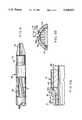
- FIG. 1is a side cross-sectional view of the tip of a catheter illustrating the electronics body, the transducer assembly, and the balloon section of a balloon angioplasty ultrasound imaging catheter embodying the present invention
- FIG. 2is a perspective view of the tip of a partially constructed diagnostic imaging catheter prior to joining the signal paths between the separated electronics body and transducer assembly;
- FIG. 3is a detailed side cross-sectional view of the tip of the imaging device portion of the catheter showing the composition of the imaging device;
- FIG. 4is a cross-sectional view of the transducer assembly taken along line 4--4 in FIG. 1;
- FIGS. 5a and 5billustratively depict an alternative embodiment of the ultrasound catheter wherein the conducting electrodes in the transducer assembly extend beyond the backing material and the transducer material;
- FIG. 6is a side cross-sectional view of the tip of a catheter illustrating the electronics body, transducer assembly, and nose assembly of an ultrasound diagnostic imaging catheter embodying the present invention
- FIGS. 7a and 7bshow cross-sectional and side-sectional views of an alternative embodiment of the present invention wherein the transducer array is configured to provide a "side-looking" view;
- FIGS. 8a, 8b and 8cshow side, forward, and top cross-sectional views of an alternative embodiment of the present invention wherein the transducer array is configured to provide a "forward-looking" view.
- the inventionwill be described in connection with a catheter used for angioplasty, it will be understood that it is not intended to be limited to such use. On the contrary, the invention is intended to cover all applications which may require imaging in a small cavity.
- An example of such an alternativewould be the use of the present invention on a catheter without the balloon. In such a case, the catheter acts as a diagnostic or monitoring device.
- Another specific alternative use of the present inventionis for measuring blood flow rates using Doppler sound imaging in conjunction with the present invention.
- the present inventionmay also be used to produce internal images of a number of ducts within a body such as the monitoring of gall stones in the bile ducts and for examination and treatment in the area of urology and gynecology.
- Another example of an application of the present inventionis the use of the ultrasound catheter for providing an image of a vessel or duct during application of laser treatment or during the removal of plaque from the walls of a vessel during an antherectomy procedure.
- the present inventionconcerns the structure of the carrier/backing material for the electronics body and transducer assembly and changes to the physical layers of the transducer assembly, the invention is intended to be incorporated in general into an ultrasound catheter imaging system of the type described in Proudian, deceased et al. U.S. Pat. No. 4,917,097 the teachings of which are incorporated herein by reference.
- FIG. 1A cross-sectional view of a catheter embodying the present invention is illustratively depicted in FIG. 1.
- the catheter shown in FIG. 1 carrying a balloon 1is of the type which is generally used for angioplasty; however, the invention can be used in conjunction with a number of catheter designs such as those illustratively depicted in FIGS. 6, 7 and 8 to provide diagnostic images and deliver treatment to small cavities of the body.
- Conventional guide wire lumens 2 and 3are telescopically fitted over a mating radiopaque guide wire lumen 4 forming a central bore 6 for a catheter guide wire during a normal catheterization procedure.
- An encapsulant 8composed of an epoxy material secures an imaging device 10 comprising the electronics body 12 and the transducer assembly 14 to the end of a catheter shaft 16.
- the imaging device 10in accordance with the present invention contains a multi-sectioned body comprising separate and distinct materials for a carrier 20 and a transducer backing material 24.
- the encapsulant 8protects and insulates a set of integrated circuits (IC's) 18 mounted upon the carrier 20.
- IC'sintegrated circuits
- the imaging device 10is positioned within a proximal sleeve 19 of the balloon 1.
- the transducer assembly 14, described hereinafter in greater detail in conjunction with FIG. 3,generally comprises a set of transducer elements 22.
- the transducer elements 22are supported in a cylindrical shape about the backing material 24.
- other transducer element configurationswill be known to those skilled in the area of transducer devices in view of the present description and in view of the state of the art.
- the balloon 1is positioned adjacent the imaging device 10 and is isolated from ambient conditions by sealing the two ends of the balloon 1 to the catheter shaft 16 and the lumen 3 in a conventional manner.
- a tube 26is embedded within the encapsulant 8 for communicating a fluid between the balloon 1 and an inflation source.
- a radiopaque marker band 27is within the expandable portion of the balloon 1 and attached to the lumen 3 to assist in locating the position of the catheter on a fluoroscope.
- a cable 28comprising an inner and outer set of wires carries electronic data and control signals between the IC's 18 and a control station computer.
- Each inner wire in the cable 28is formed from a solid conductor protected by an insulating coating.
- the outer wiresare spiraled a number of times around the cable 28 in order to shield the signals carried by the inner wires of the cable 28.
- the cableis coated with an insulating material.
- FIG. 2a perspective view is provided of the tip of a partially constructed diagnostic imaging catheter 10 prior to joining the signal paths between the separated electronics body 12 and transducer assembly 14 in order to show the distinct first and second portions of the imaging device 10 comprising the transducer assembly 14 and the electronics body 12.
- the proximal sleeve 19 and the epoxy encapsulant 8 covering the imaging device 10have been removed to expose the integrated circuit chips 18 and associated electronic constructions.
- a nose cone 25provides a blunted lead surface for the ultrasound imaging catheter in order to prevent damage to a vessel as the catheter is guided through the vessel.
- the radiopaque guide wire lumen 4aids in the positioning of the catheter.
- the radiopaque guide wire lumen 4also holds both the electronics body 12 and the transducer assembly 14.
- the outer diameter of the radiopaque guide wire lumen 4is approximately 0.5 millimeters.
- the radiopaque guide wire lumen 4provides the additional function of acting as a guide for precisely positioning the electronics body 12 and transducer assembly 14 in order to mate a set of 64 conductor lines 30 from the IC's 18 mounted upon the electronics body 12 to a set of 64 transducer contacts 32 of the transducer assembly 14 in a manner shown in FIG. 3.
- the gap between the radiopaque guide wire lumen 4 and both the carrier 20 and the backing material 24must be very small and should not be greater than approximately 25 ⁇ m. This minimized gap ensures proper radial alignment of the conductor lines 30 and transducer contacts 32.
- the four IC's 18are of an inverted chip design known to those skilled in the area of the semiconductor chip fabrication art and are bonded to a set of conductive pads 34 formed on the carrier 20.
- the conductive pads 34interconnect the IC's 18 to their neighboring chips and provide a connection between the IC's 18 and the cable 28 that communicatively couples the IC's 18 to a signal processor located outside the patient.
- the padsalso connect the IC's 18 to the conductor lines 30.
- the conductor lines 30link the IC's 18 to a set of 64 electrodes that define the transducer elements in the transducer assembly 14.
- Each of the IC's 18has 16 channels associated with 16 transducer elements defined by 16 transducer electrodes in the transducer assembly 14. Each of the four IC's 18 is responsible for sequentially transmitting and receiving electrical signals in the ultrasonic frequency range on one or more of its 16 channels linked by conductor lines 30 to an associated transducer element in the transducer assembly 14.
- the four IC's 18provide a multiplexing function that distributes excitation pulses from a signal processor to one or more of the transducer elements. At any given time one or more of the 16 channels on each of the IC's 18 is free to be excited by an excitation signal or to receive reflections or echoes by means of activation control signals stored on the IC's 18.
- the electrical signals generated from the reflections impinging on the active transducer elementsare amplified and sent via the transmission cable line 28 to the external signal processor.
- FIG. 3a detailed side cross-sectional view of the imaging portion of the catheter of FIG. 1 is illustrated to show the structure and materials of the imaging device 10.
- the electronics body 12 and the transducer assembly 14are shown in their mated state as they would exist in the final construction of the imaging catheter.
- the layers of the transducer assemblyare shown in detail in FIG. 3 it will be helpful to refer to FIG. 4, a cross section view of the transducer assembly taken along line 4--4 of FIG. 2, during the description of the ringed layers of the transducer assembly 14.
- the carrier 20is bonded to the radiopaque guide wire lumen 4 by means of a glue layer 36 comprising any commercially available medical grade cyanoacrylate epoxy.
- a glue layer 36comprising any commercially available medical grade cyanoacrylate epoxy.
- Onemay substitute any material or structure that satisfactorily immobilizes the electronics body 12 for the glue layer 36.
- the space between the radiopaque guide wire lumen 4 and the carrier 20 filled by the glue layer 36must be very small in order for the radiopaque guide wire lumen 4 to assist in the matching of the electrical contacts between the electronics body 12 and the transducer assembly 14.
- the carrier 20 in the preferred embodiment of the inventionis formed from a rigid, strong material having a low thermal expansion coefficient.
- the carrier 20must be capable of withstanding temperatures in excess of 200 degrees Celsius to which the electronics body 12 is subjected during the process of bonding the set of IC's 18 to the carrier 20. Furthermore, during operation of the ultrasound catheter, self-heating of the IC's 18 may cause expansion of the carrier 20. If the thermal expansion of the carrier 20 is too great, shear forces exerted by the carrier 20 upon the conductive pads 34 create a substantial risk of failure of the electrical connection between the contacts of the IC's 18 and the conductor lines 30.
- Aluminum oxide(Al 2 O 3 ) possesses the aforementioned desired characteristics for the carrier 20; however, other suitable substitutes for this material are well known to those skilled in the art of hybrid circuits.
- Aluminum oxideis also characterized by a very high acoustic impedance (approximately 40 MRayls) and relatively low loss. As will be explained below, these acoustical properties make Aluminum oxide a poor candidate for use as the transducer backing material for applications involving highly sensitive transducer elements.
- An encapsulant 8is applied to the outer surface of the electronics body 12 in order to provide a more cylindrical shape to the catheter assembly and to insulate the electronic circuitry.
- the encapsulant 8generally comprises any commercially available medical grade UV-curable acrylic.
- the outside of the electronics bodymay be covered by a protective layer.
- the protective layeris made of, for example, parylene. Other suitable materials for the protective layer will be known to those skilled in the art of ultrasound catheters or other medical instruments which are inserted within the body.
- the protective layerconsists of the proximal sleeve 19 in the balloon angioplasty catheter shown in FIG. 1 or a sheath 38 in the case of a diagnostic imaging catheter such as the one illustrated in FIG. 6.
- the backing material 24 for the transducer assembly 14is preferably formed from a material characterized by a relatively low acoustic impedance ( ⁇ 10 MRayls) and high loss coefficient (on the order of 20 to 40 dB/mm). This is necessitated by the use of highly sensitive transducer materials such as the PZT composites used for a transducer material 40 whose superior signal sensitivity is otherwise negated by the ringing effect caused by a backing material having a high acoustic impedance and low loss. For this reason, Aluminum oxide is not a preferred material for the backing material 24 for the transducer assembly 14.
- a separate and different materialis used to form the backing material 24 for the ultrasound catheter of the present invention.
- a preferred material for the backing material 24is an epoxy resin filled with either rubber particles or glass microspheres.
- An example of such a resinis "light-weld" 183-M by Dymax Corp., Torrington, Conn.
- Other suitable materials having low acoustic impedance and high losswill be known to those of ordinary skill in the art of ultrasound imaging.
- airis an ideal backing material, transducer assemblies using an air backing are difficult to achieve in practice.
- the ultrasound catheter of the present inventionis characterized by an imaging device 10 having separate and distinct carrier/backing materials that exhibit greatly contrasting characteristics.
- the two distinct materialsprovide desirable structural and acoustical characteristics for satisfying the dissimilar requirements for the electronics body 12 and the transducer assembly 14.
- the outer layers of the transducer assembly 14are separately manufactured as a planar sheet. They comprise a first set of 64 conducting electrodes 42, the transducer material 40, a continuous layer conducting electrode 44, and a matching layer 46. After the layers are fabricated, the planar sheet of transducer elements 22 is wrapped around the backing material 24 and bonded by means of a glue layer 48. Depending on the mechanical and acoustic properties of the transducer assembly 14, physical isolation of the transducer elements 22 from one another may be desirable.
- the outer diameter of the backing material 24must be manufactured within very close tolerances so that the ends of the planar sheet of transducer elements, when joined to form a cylinder around the backing material 24, meet with minimal gap or overlap.
- the planar transducer assembly 14may be formed into a cylinder of exact outer diameter concentrically around the radiopaque lumen 4 and the gap between the lumen 4 and the transducer assembly 14 is filled with the backing material 24. This ensures that the spacing between the transducer array elements at the opposite ends of the cylindrically wrapped planar sheet have the same spacing as the other transducer array elements.
- the error in the circumference of the transducer sheet, when wrapped around the lumen 4,should be less than (plus or minus) 8 ⁇ m.
- the inner diameter of the backing material 24must closely match the outer diameter of the radiopaque guide wire lumen 4 in order to facilitate the mating of electrical contacts between the electronics body 12 and the transducer assembly 14.
- the concentric rings comprising the afore-described layers of the transducer assembly 14are illustratively depicted in FIG. 4 showing a cross-sectional view of the transducer assembly taken on line 4--4 of FIG. 1.
- planar sheet transducer element fabrication methodis the absence of capacitive glue layers previously present between the transducer material 40 and each of the conducting electrodes 42 and 44. If the capacitive glue layer remained in the presently described ultrasound catheter, an increased capacitance attributable to the higher dielectric constant of the PZT composite transducer material 40 would negate the improved signal sensitivity of the preferred transducer material.
- planar sheets comprising the transducer elementsare: Precision Acoustic Devices, Fremont, Calif.; Acoustic Imaging, Phoenix, Ariz.; Echo Ultrasound, Lewistown, Pa.; Vermon S. A., Tours, France; and Imasonic, Besancon, France.
- the transducer materialmay be polarized by means of a high voltage on the order of 5,000 Volts applied between the first set of conducting electrodes 42 and the continuous conducting electrode 44. Therefore, it is desirable to perform the polarization procedure on a separated assembly to isolate the transducer assembly 14 from the electronics body 12 since application of such a high voltage to the IC's 18 would destroy the electronic circuitry of the IC's 18.
- the layer of glue 48bonds the backing material 24 to the first set of conducting electrodes 42 spaced evenly about the circumference of the backing material 24.
- the first set of conducting electrodes 42defines the individual transducer elements in the transducer array.
- the first set of conducting electrodes 42is attached to the set of 64 transducer contacts 32.
- Connection material 50electrically couples each one of the transducer contacts 32, corresponding to a single transducer element, to a corresponding one of the conductor lines 30, thereby providing an electronic signal path between the transducer elements 22 and the IC's 18.
- the connection materialcomprises any of several known suitable conductors such as silver or gold loaded epoxy droplets, solder or gold bumps, or solder tape.
- FIGS. 5A and 5Billustratively depict an alternative embodiment of the ultrasound catheter wherein copper conducting electrodes 42 of the transducer assembly 14 extend beyond the backing material 24 and the transducer material 40.
- the portion of the conducting electrodes 42 extending beyond the backing material 24 and overlapping the conductor lines 30 when the transducer assembly 14 is joined to the electronics body 12facilitates the use of a well known gap welder to fuse the individual conductor lines 30 to the corresponding conducting electrodes 42.
- FIG. 5Ashows a cross-sectional view of a partially constructed ultrasound catheter to show the above described connection scheme.
- the use of a gap weldereliminates the need to deposit individual drops of solder material 50 as shown in FIG. 3.
- the elimination of solder dropletspotentially simplifies the design of the electronics carrier 20 that may otherwise require scalloping of the carrier at the end proximate the transducer assembly 14 in order to facilitate proper deposition of the droplets to fuse the conductor lines 30 and the transducer contacts 32.
- Other advantages of this connection schemeinclude better bonding of the conductors, simpler assembly techniques, and enhanced mechanical stability.
- connection scheme portrayed in FIGS. 5A and 5Bis the potential to automate the process of bonding the conducting electrodes 42 to the conductor lines 30.
- the conductor lines 30are matched to the conducting electrodes 42.
- a tip 70 of a gap welderis placed above one of the matched lines.
- the tip 70presses a conducting electrode 42a to a corresponding conductor line 30a.
- a low voltage, high electrical currentpasses between the electrodes of the tip 70.
- the electrical currentfuses the conducting electrode 42a to the conductor line 30a.
- the catheter assemblyis rotated so that a next matched set of lines (42b and 30b) is below the tip 70 and the welding process is repeated. The welding continues until all the lines have been fused.
- the efficiency rating of the transducer materialis high (greater than 50%); the bandwidth should be high (greater than 50% of center frequency); there should be good matching among the transducer elements; there should be low insertion loss (less than -40 dB); and the center frequency should be around 20 MHz. Therefore, in the preferred embodiment of the present invention, the transducer material 24 is any one of many known suitable PZT composites.
- the radial thickness of the transducer layer 40is preferably one-half wavelength thickness or an odd multiple of half wavelengths of the intended center operating frequency of the ultrasound catheter. As explained in Biomedical Ultrasonics, at page 53, this enables the transducer to resonate at the center operating frequency of the ultrasound catheter. In the present embodiment, the radial thickness of the transducer material 24 is approximately 0.1 millimeters.
- the backing material 24In order to take advantage of the superior signal sensitivity of transducers formed from PZT composites, the backing material 24 must have a low acoustic impedance. Therefore, the aluminum oxide carrier 20 having a high acoustic impedance should not be used as the backing material 24. Instead the previous monolithic carrier for both the electronics body 12 and the transducer assembly 14 is replaced by the separated carrier/backing sections 20 and 24.
- the continuous conducting electrode 44 covering the outer surface of the transducer material 40is the ground plane for the transducer elements 22. It is preferably a layer of gold metal deposited upon the surface of the matching layer 46 by means of sputtering. However, other suitable conductors and methods to deposit the conductor will be known to those skilled in the art of transducers fabrication. Though not essential to the proper operation of the ultrasound catheter, it is preferred to connect in a known manner the continuous conducting electrode 44 to a ground line provided by the cable 28. The ground line runs along the electronics carrier 20 and is connected to the continuous conducting electrode after the electronics body 12 and the transducer assembly 14 have been joined. One possible way to connect the ground wire is shown in FIG. 2 of the Proudian, deceased et al. U.S. Pat. No. 4,917,097.
- the transducer elements 22are enclosed by a matching layer 46.
- a matching layer 46As explained in Biomedical Ultrasonics, by P. N. T. Wells, Academic Press 1977, at page 54, the efficiency of transmission into the load may be increased by an impedance matching layer of quarter wavelength thickness.
- the matching layer 46comprises a loaded epoxy and is approximately 0.06 mm. thick.
- Alternative appropriate matching layer materials and their thicknesseswill be apparent to those of ordinary skill in the art of ultrasonic imaging.
- the electronics body 12 and the transducer assembly 14are bonded together by a layer of glue 52 and the electrical connections between the electronics body 12 and the transducer assembly 14 are electrically coupled in a manner previously described.
- the cable 28 containing the leads from the signal processor for the ultrasound catheter(previously described in the Proudian et al. '097 patent) are bonded to the conductive pads 34 on the carrier 20 in a known manner.
- FIG. 6shows an alternative embodiment of the present invention, wherein the imaging device 10 is included in a diagnostic imaging catheter that does not contain a balloon 1. Portions of the diagnostic imaging catheter have been removed to reveal the cable 28 and the lumen 2. Since there is no balloon 1 in the imaging catheter shown in FIG. 6, there is of course no tube 26 for filling and draining a fluid from the balloon. Instead, the catheter is fitted with a nose cone 25. The nose cone 25 provides a blunted lead surface for the ultrasound imaging catheter in order to prevent damage to the walls of a cavity as the catheter is inserted. A sheath 38 covers the epoxy resin 8 thereby guarding against contamination of a patient's blood and possibly electrical shock.
- the sheath 38is preferably constructed of parylene, though other suitable substitutes will be known to those skilled in the art of medical instruments that are inserted within a body.
- the structure of the imaging catheter shown in FIG. 6is otherwise unchanged from the structure of the balloon angioplasty ultrasound imaging catheter illustrated in FIG. 1.
- transducer arrayconfigured as a cylinder about a cylindrical core
- FIGS. 7 and 8Examples of such configurations are shown in FIGS. 7 and 8.
- Other configurations of transducer arrays for an ultrasound catheterwill be known to those skilled in the art in view of the present description of this invention.
- FIGS. 7A and 7Billustrate side and cross-sectional views of a side-looking linear array imaging catheter.
- the transducer elements 22are arranged in a plane and perpendicular to the direction of insertion of the imaging catheter. This arrangement provides an image along the length of a cavity.
- the IC's 18are connected to the cable 28 in the same manner as the previously described embodiments of the invention.
- the IC's 18are mounted upon an electronics carrier 20 of the type previously described in connection with the preferred embodiment of the invention shown in FIG. 1.
- the IC'sare electrically coupled to the transducer elements 22 by conductor lines 30.
- the backing material for the transducer elements 22forms the encapsulant 8 in this case.
- FIGS. 8A, 8B and 8Cillustrate side, forward, and top cross-sectional views of a forward-looking "endfire" imaging catheter shown in FIG. 1.
- the encapsulant 8which is also the backing material for the transducers 22, has been partially removed to reveal the placement and orientation of the electronics portion.
- the transducer elements 22are arranged as a planar array mounted upon the leading face of the catheter.
- the guide wire lumen 4is mounted adjacent the ultrasonic imaging device. The diameter of the guide wire lumen 4 is approximately 0.3 mm or about one-third the diameter of the imaging catheter.
- This arrangementprovides a forward looking view of a cavity.
- the dimensions of the field of vieware determined by the size of the array, the number of elements, the element dimensions and frequency.
- the IC's 18are connected to the cable 28 in the same manner as the previously described embodiments of the invention.
- the IC's 18are mounted upon a carrier 20 of the type previously described in connection with the preferred embodiment of the invention shown in FIG. 1.
- the IC'sare electrically coupled to the transducer elements 22 by conductor lines 30.
- the encapsulant 8may form the backing material for the transducer elements 22.
Landscapes
- Health & Medical Sciences (AREA)
- Engineering & Computer Science (AREA)
- Life Sciences & Earth Sciences (AREA)
- Physics & Mathematics (AREA)
- Remote Sensing (AREA)
- Radar, Positioning & Navigation (AREA)
- Acoustics & Sound (AREA)
- Radiology & Medical Imaging (AREA)
- Biophysics (AREA)
- Biomedical Technology (AREA)
- Heart & Thoracic Surgery (AREA)
- Medical Informatics (AREA)
- Molecular Biology (AREA)
- Surgery (AREA)
- Animal Behavior & Ethology (AREA)
- General Health & Medical Sciences (AREA)
- Public Health (AREA)
- Veterinary Medicine (AREA)
- Pathology (AREA)
- Nuclear Medicine, Radiotherapy & Molecular Imaging (AREA)
- Mechanical Engineering (AREA)
- Gynecology & Obstetrics (AREA)
- Computer Networks & Wireless Communication (AREA)
- General Physics & Mathematics (AREA)
- Multimedia (AREA)
- Hematology (AREA)
- Ultra Sonic Daignosis Equipment (AREA)
- Media Introduction/Drainage Providing Device (AREA)
- Surgical Instruments (AREA)
- Particle Formation And Scattering Control In Inkjet Printers (AREA)
Abstract
Description
Claims (17)
Priority Applications (25)
| Application Number | Priority Date | Filing Date | Title |
|---|---|---|---|
| US08/012,251US5368037A (en) | 1993-02-01 | 1993-02-01 | Ultrasound catheter |
| DE69435314TDE69435314D1 (en) | 1993-02-01 | 1994-01-14 | Method for producing an ultrasound catheter |
| AT03075230TATE481034T1 (en) | 1993-02-01 | 1994-01-14 | METHOD FOR PRODUCING AN ULTRASONIC CATHETER |
| PCT/US1994/000474WO1994017734A1 (en) | 1993-02-01 | 1994-01-14 | Ultrasound catheter |
| DE69430490TDE69430490T3 (en) | 1993-02-01 | 1994-01-14 | Method for producing a transducer arrangement for imaging |
| EP96202546AEP0750883B2 (en) | 1993-02-01 | 1994-01-14 | Method of making a transducer assembly for an imaging device |
| EP94906070AEP0637937B1 (en) | 1993-02-01 | 1994-01-14 | Ultrasound catheter probe |
| JP51804094AJP3732854B2 (en) | 1993-02-01 | 1994-01-14 | Ultrasound catheter |
| AT94906070TATE236573T1 (en) | 1993-02-01 | 1994-01-14 | ULTRASONIC CATHETER SENSOR |
| CA002133475ACA2133475C (en) | 1993-02-01 | 1994-01-14 | Ultrasound catheter |
| DE69432448TDE69432448T2 (en) | 1993-02-01 | 1994-01-14 | ULTRASONIC CATHETER SENSOR |
| AT96202546TATE216570T1 (en) | 1993-02-01 | 1994-01-14 | METHOD FOR PRODUCING A TRANSDUCER ARRANGEMENT FOR IMAGE GENERATION |
| EP03075230AEP1327417B1 (en) | 1993-02-01 | 1994-01-14 | Method of manufacturing an ultrasound catheter |
| CA002235947ACA2235947C (en) | 1993-02-01 | 1994-01-14 | Ultrasound transducer assembly and catheter |
| US08/234,848US5453575A (en) | 1993-02-01 | 1994-04-28 | Apparatus and method for detecting blood flow in intravascular ultrasonic imaging |
| US08/516,538US5603327A (en) | 1993-02-01 | 1995-08-18 | Ultrasound catheter probe |
| US08/712,166US5779644A (en) | 1993-02-01 | 1996-09-11 | Ultrasound catheter probe |
| US08/935,930US5938615A (en) | 1993-02-01 | 1997-09-23 | Ultrasound catheter probe |
| US09/324,692US6123673A (en) | 1993-02-01 | 1999-06-02 | Method of making an ultrasound transducer assembly |
| US09/658,323US6283920B1 (en) | 1993-02-01 | 2000-09-08 | Ultrasound transducer assembly |
| US09/906,302US6962567B2 (en) | 1993-02-01 | 2001-07-16 | Ultrasound transducer assembly |
| JP2005251527AJP2005342535A (en) | 1993-02-01 | 2005-08-31 | Ultrasound catheter probe |
| JP2005251525AJP3831743B2 (en) | 1993-02-01 | 2005-08-31 | Ultrasonic catheter / probe |
| US11/221,165US20060058681A1 (en) | 1993-02-01 | 2005-09-07 | Ultrasound transducer assembly |
| US11/431,129US20070016071A1 (en) | 1993-02-01 | 2006-05-09 | Ultrasound transducer assembly |
Applications Claiming Priority (1)
| Application Number | Priority Date | Filing Date | Title |
|---|---|---|---|
| US08/012,251US5368037A (en) | 1993-02-01 | 1993-02-01 | Ultrasound catheter |
Related Child Applications (1)
| Application Number | Title | Priority Date | Filing Date |
|---|---|---|---|
| US08/234,848Continuation-In-PartUS5453575A (en) | 1993-02-01 | 1994-04-28 | Apparatus and method for detecting blood flow in intravascular ultrasonic imaging |
Publications (1)
| Publication Number | Publication Date |
|---|---|
| US5368037Atrue US5368037A (en) | 1994-11-29 |
Family
ID=21754054
Family Applications (1)
| Application Number | Title | Priority Date | Filing Date |
|---|---|---|---|
| US08/012,251Expired - LifetimeUS5368037A (en) | 1993-02-01 | 1993-02-01 | Ultrasound catheter |
Country Status (7)
| Country | Link |
|---|---|
| US (1) | US5368037A (en) |
| EP (3) | EP0750883B2 (en) |
| JP (3) | JP3732854B2 (en) |
| AT (3) | ATE236573T1 (en) |
| CA (2) | CA2235947C (en) |
| DE (3) | DE69435314D1 (en) |
| WO (1) | WO1994017734A1 (en) |
Cited By (141)
| Publication number | Priority date | Publication date | Assignee | Title |
|---|---|---|---|---|
| US5488954A (en)* | 1994-09-09 | 1996-02-06 | Georgia Tech Research Corp. | Ultrasonic transducer and method for using same |
| US5603327A (en)* | 1993-02-01 | 1997-02-18 | Endosonics Corporation | Ultrasound catheter probe |
| US5606975A (en)* | 1994-09-19 | 1997-03-04 | The Board Of Trustees Of The Leland Stanford Junior University | Forward viewing ultrasonic imaging catheter |
| US5690114A (en)* | 1995-06-29 | 1997-11-25 | Teratech Corporation | Portable ultrasound imaging system |
| WO1998011823A1 (en) | 1996-09-20 | 1998-03-26 | Cardiovascular Imaging Systems, Inc. | Three-dimensional intraluminal ultrasound image reconstruction |
| US5733281A (en)* | 1996-03-19 | 1998-03-31 | American Ablation Co., Inc. | Ultrasound and impedance feedback system for use with electrosurgical instruments |
| US5738100A (en)* | 1995-06-30 | 1998-04-14 | Terumo Kabushiki Kaisha | Ultrasonic imaging catheter |
| EP0853919A2 (en) | 1997-01-08 | 1998-07-22 | Endosonics Corporation | A high resolution intravascular ultrasound transducer assembly having a flexible substrate and method for manufacture thereof |
| US5795299A (en)* | 1997-01-31 | 1998-08-18 | Acuson Corporation | Ultrasonic transducer assembly with extended flexible circuits |
| US5797848A (en)* | 1997-01-31 | 1998-08-25 | Acuson Corporation | Ultrasonic transducer assembly with improved electrical interface |
| EP0871043A2 (en) | 1997-04-08 | 1998-10-14 | EndoSonics Corporation | A method and apparatus for creating a color blood flow image based upon ultrasonic echo signals received by an intravascular ultrasound imaging probe |
| US5846205A (en)* | 1997-01-31 | 1998-12-08 | Acuson Corporation | Catheter-mounted, phased-array ultrasound transducer with improved imaging |
| US5876344A (en)* | 1997-12-09 | 1999-03-02 | Endosonics Corporation | Modular imaging/treatment catheter assembly and method |
| US5876345A (en)* | 1997-02-27 | 1999-03-02 | Acuson Corporation | Ultrasonic catheter, system and method for two dimensional imaging or three-dimensional reconstruction |
| US5938616A (en)* | 1997-01-31 | 1999-08-17 | Acuson Corporation | Steering mechanism and steering line for a catheter-mounted ultrasonic transducer |
| US5954654A (en)* | 1997-01-31 | 1999-09-21 | Acuson Corporation | Steering mechanism and steering line for a catheter-mounted ultrasonic transducer |
| US6014473A (en)* | 1996-02-29 | 2000-01-11 | Acuson Corporation | Multiple ultrasound image registration system, method and transducer |
| US6017311A (en)* | 1997-09-24 | 2000-01-25 | Fuji Photo Optical Co., Ltd. | Ultrasound probe having an insulating sleeve member |
| WO2000004854A1 (en)* | 1998-07-23 | 2000-02-03 | Durect Corporation | Fluid transfer and diagnostic system for treating the inner ear |
| US6030346A (en)* | 1996-02-21 | 2000-02-29 | The Whitaker Corporation | Ultrasound imaging probe assembly |
| US6029671A (en)* | 1991-07-16 | 2000-02-29 | Heartport, Inc. | System and methods for performing endovascular procedures |
| US6045508A (en)* | 1997-02-27 | 2000-04-04 | Acuson Corporation | Ultrasonic probe, system and method for two-dimensional imaging or three-dimensional reconstruction |
| US6106472A (en)* | 1995-06-29 | 2000-08-22 | Teratech Corporation | Portable ultrasound imaging system |
| US6110314A (en)* | 1994-03-11 | 2000-08-29 | Intravascular Research Limited | Ultrasonic transducer array and method of manufacturing the same |
| US6117083A (en)* | 1996-02-21 | 2000-09-12 | The Whitaker Corporation | Ultrasound imaging probe assembly |
| US6306097B1 (en) | 1999-06-17 | 2001-10-23 | Acuson Corporation | Ultrasound imaging catheter guiding assembly with catheter working port |
| USD455210S1 (en) | 1997-01-31 | 2002-04-02 | Acuson Corporation | Ultrasonic transducer assembly controller |
| US6423002B1 (en) | 1999-06-24 | 2002-07-23 | Acuson Corporation | Intra-operative diagnostic ultrasound multiple-array transducer probe and optional surgical tool |
| US6464645B1 (en) | 1997-01-31 | 2002-10-15 | Acuson Corporation | Ultrasonic transducer assembly controller |
| USD465024S1 (en) | 1998-01-31 | 2002-10-29 | Acuson Corporation | Ultrasonic transducer assembly controller |
| US6589182B1 (en) | 2001-02-12 | 2003-07-08 | Acuson Corporation | Medical diagnostic ultrasound catheter with first and second tip portions |
| US6689087B2 (en)* | 2001-03-28 | 2004-02-10 | Cybersonics, Inc. | Floating probe for ultrasonic transducers |
| US20040054287A1 (en)* | 2002-08-29 | 2004-03-18 | Stephens Douglas Neil | Ultrasonic imaging devices and methods of fabrication |
| US20040067000A1 (en)* | 2002-10-07 | 2004-04-08 | Bates Kenneth N. | Systems and methods for minimally-invasive optical-acoustic imaging |
| US20040082844A1 (en)* | 1998-03-05 | 2004-04-29 | Vardi Gil M. | Optical-acoustic imaging device |
| US20040082884A1 (en)* | 2001-03-28 | 2004-04-29 | Dharmendra Pal | Floating probe for ultrasonic transducers |
| WO2004020018A3 (en)* | 2002-08-29 | 2004-05-13 | Volcano Therapeutics Inc | Ultrasonic imaging devices and methods of fabrication |
| US20050113699A1 (en)* | 2003-11-21 | 2005-05-26 | Haugen Geir U. | Ultrasound probe sub-aperture processing |
| US20050113698A1 (en)* | 2003-11-21 | 2005-05-26 | Kjell Kristoffersen | Ultrasound probe transceiver circuitry |
| US20050113694A1 (en)* | 2003-11-21 | 2005-05-26 | Haugen Geir U. | Ultrasound probe distributed beamformer |
| US20050171478A1 (en)* | 1998-01-13 | 2005-08-04 | Selmon Matthew R. | Catheter system for crossing total occlusions in vasculature |
| EP1621135A1 (en)* | 2004-07-29 | 2006-02-01 | Fujinon Corporation | Ultrasonic endoscope |
| WO2006003606A3 (en)* | 2004-06-29 | 2006-05-11 | Koninkl Philips Electronics Nv | System simplification for an ultrasound-based perfusion detection system |
| US20070016071A1 (en)* | 1993-02-01 | 2007-01-18 | Volcano Corporation | Ultrasound transducer assembly |
| US20070116408A1 (en)* | 2005-11-22 | 2007-05-24 | Eberle Michael J | Optical imaging probe connector |
| US7226417B1 (en) | 1995-12-26 | 2007-06-05 | Volcano Corporation | High resolution intravascular ultrasound transducer assembly having a flexible substrate |
| US20070167827A1 (en)* | 2005-11-12 | 2007-07-19 | Donald Masters | Systems And Methods For Reducing Noise In An Imaging Catheter System |
| US20080009745A1 (en)* | 2006-04-04 | 2008-01-10 | Volcano Corporation | Ultrasound catheter and hand-held device for manipulating a transducer on the catheter's distal end |
| US7500952B1 (en) | 1995-06-29 | 2009-03-10 | Teratech Corporation | Portable ultrasound imaging system |
| US20090143702A1 (en)* | 2001-01-26 | 2009-06-04 | Lake Region Manufacturing, Inc. | Non-metallic guide wire |
| US20090183350A1 (en)* | 2008-01-17 | 2009-07-23 | Wetsco, Inc. | Method for Ultrasound Probe Repair |
| US20100228130A1 (en)* | 2009-03-09 | 2010-09-09 | Teratech Corporation | Portable ultrasound imaging system |
| US7830069B2 (en) | 2004-04-20 | 2010-11-09 | Sunnybrook Health Sciences Centre | Arrayed ultrasonic transducer |
| US7901358B2 (en) | 2005-11-02 | 2011-03-08 | Visualsonics Inc. | High frequency array ultrasound system |
| US8241217B2 (en) | 1995-06-29 | 2012-08-14 | Teratech Corporation | Portable ultrasound imaging data |
| US8303505B2 (en) | 2005-12-02 | 2012-11-06 | Abbott Cardiovascular Systems Inc. | Methods and apparatuses for image guided medical procedures |
| US8316518B2 (en) | 2008-09-18 | 2012-11-27 | Visualsonics Inc. | Methods for manufacturing ultrasound transducers and other components |
| US8560048B2 (en) | 2008-10-02 | 2013-10-15 | Vascular Imaging Corporation | Optical ultrasound receiver |
| US20140180118A1 (en)* | 2012-12-20 | 2014-06-26 | Volcano Corporation | Catheter Assembly with a Shortened Tip |
| WO2014105442A1 (en)* | 2012-12-28 | 2014-07-03 | Volcano Corporation | Transducer assembly for an imaging device |
| WO2014113188A2 (en) | 2012-12-20 | 2014-07-24 | Jeremy Stigall | Locating intravascular images |
| US20140261985A1 (en)* | 2013-03-13 | 2014-09-18 | Biosense Webster (Israel), Ltd. | Method for making a low ohmic pressure-contact electrical connection between split ring electrode and lead wire |
| WO2015106188A1 (en) | 2014-01-10 | 2015-07-16 | Volcano Corporation | Detecting endoleaks associated with aneurysm repair |
| WO2015106197A2 (en) | 2014-01-10 | 2015-07-16 | Volcano Corporation | Detecting endoleaks associated with aneurysm repair |
| WO2015108973A1 (en) | 2014-01-14 | 2015-07-23 | Volcano Corporation | Methods and systems for clearing thrombus from a vascular access site |
| WO2015108942A1 (en) | 2014-01-14 | 2015-07-23 | Volcano Corporation | Vascular access evaluation and treatment |
| WO2015108941A1 (en) | 2014-01-14 | 2015-07-23 | Volcano Corporation | Devices and methods for forming vascular access |
| WO2015108984A1 (en) | 2014-01-14 | 2015-07-23 | Volcano Corporation | Catheter assembly for vascular access site creation |
| WO2015156945A1 (en) | 2014-04-11 | 2015-10-15 | Jeremy Stigall | Imaging and treatment device |
| US9164084B2 (en) | 2012-01-31 | 2015-10-20 | Purdue Research Foundation | Methods for determining aggressiveness of a cancer and treatment thereof |
| US9173047B2 (en) | 2008-09-18 | 2015-10-27 | Fujifilm Sonosite, Inc. | Methods for manufacturing ultrasound transducers and other components |
| US9184369B2 (en) | 2008-09-18 | 2015-11-10 | Fujifilm Sonosite, Inc. | Methods for manufacturing ultrasound transducers and other components |
| WO2016009337A2 (en) | 2014-07-15 | 2016-01-21 | Koninklijke Philips N.V. | Devices and methods for intrahepatic shunts |
| WO2016027198A1 (en) | 2014-08-21 | 2016-02-25 | Koninklijke Philips N.V. | Device and methods for crossing occlusions |
| US9286673B2 (en) | 2012-10-05 | 2016-03-15 | Volcano Corporation | Systems for correcting distortions in a medical image and methods of use thereof |
| US9292918B2 (en) | 2012-10-05 | 2016-03-22 | Volcano Corporation | Methods and systems for transforming luminal images |
| US9295447B2 (en) | 2011-08-17 | 2016-03-29 | Volcano Corporation | Systems and methods for identifying vascular borders |
| US9301687B2 (en) | 2013-03-13 | 2016-04-05 | Volcano Corporation | System and method for OCT depth calibration |
| US9307926B2 (en) | 2012-10-05 | 2016-04-12 | Volcano Corporation | Automatic stent detection |
| US9324141B2 (en) | 2012-10-05 | 2016-04-26 | Volcano Corporation | Removal of A-scan streaking artifact |
| US9360630B2 (en) | 2011-08-31 | 2016-06-07 | Volcano Corporation | Optical-electrical rotary joint and methods of use |
| US9367965B2 (en) | 2012-10-05 | 2016-06-14 | Volcano Corporation | Systems and methods for generating images of tissue |
| US9383263B2 (en) | 2012-12-21 | 2016-07-05 | Volcano Corporation | Systems and methods for narrowing a wavelength emission of light |
| EP2934321A4 (en)* | 2012-12-21 | 2016-07-20 | Paul Hoseit | Imaging catheter for imaging from within balloon |
| WO2016132241A1 (en) | 2015-02-20 | 2016-08-25 | Koninklijke Philips N.V. | Atherectomy apparatus with imaging |
| US9478940B2 (en) | 2012-10-05 | 2016-10-25 | Volcano Corporation | Systems and methods for amplifying light |
| US9486143B2 (en) | 2012-12-21 | 2016-11-08 | Volcano Corporation | Intravascular forward imaging device |
| US9596993B2 (en) | 2007-07-12 | 2017-03-21 | Volcano Corporation | Automatic calibration systems and methods of use |
| US9612105B2 (en) | 2012-12-21 | 2017-04-04 | Volcano Corporation | Polarization sensitive optical coherence tomography system |
| US9622706B2 (en) | 2007-07-12 | 2017-04-18 | Volcano Corporation | Catheter for in vivo imaging |
| US9709379B2 (en) | 2012-12-20 | 2017-07-18 | Volcano Corporation | Optical coherence tomography system that is reconfigurable between different imaging modes |
| US9770172B2 (en) | 2013-03-07 | 2017-09-26 | Volcano Corporation | Multimodal segmentation in intravascular images |
| WO2017198800A1 (en) | 2016-05-20 | 2017-11-23 | Koninklijke Philips N.V. | Devices and methods for stratification of patients for renal denervation based on intravascular pressure and cross-sectional lumen measurements |
| US9858668B2 (en) | 2012-10-05 | 2018-01-02 | Volcano Corporation | Guidewire artifact removal in images |
| US9867530B2 (en) | 2006-08-14 | 2018-01-16 | Volcano Corporation | Telescopic side port catheter device with imaging system and method for accessing side branch occlusions |
| US10058284B2 (en) | 2012-12-21 | 2018-08-28 | Volcano Corporation | Simultaneous imaging, monitoring, and therapy |
| US10070827B2 (en) | 2012-10-05 | 2018-09-11 | Volcano Corporation | Automatic image playback |
| US10166003B2 (en) | 2012-12-21 | 2019-01-01 | Volcano Corporation | Ultrasound imaging with variable line density |
| US10191220B2 (en) | 2012-12-21 | 2019-01-29 | Volcano Corporation | Power-efficient optical circuit |
| US10219887B2 (en) | 2013-03-14 | 2019-03-05 | Volcano Corporation | Filters with echogenic characteristics |
| US10219780B2 (en) | 2007-07-12 | 2019-03-05 | Volcano Corporation | OCT-IVUS catheter for concurrent luminal imaging |
| US10226597B2 (en) | 2013-03-07 | 2019-03-12 | Volcano Corporation | Guidewire with centering mechanism |
| US10238367B2 (en) | 2012-12-13 | 2019-03-26 | Volcano Corporation | Devices, systems, and methods for targeted cannulation |
| US10251606B2 (en) | 2014-01-14 | 2019-04-09 | Volcano Corporation | Systems and methods for evaluating hemodialysis arteriovenous fistula maturation |
| US10292677B2 (en) | 2013-03-14 | 2019-05-21 | Volcano Corporation | Endoluminal filter having enhanced echogenic properties |
| US10327695B2 (en) | 2012-12-21 | 2019-06-25 | Volcano Corporation | Functional gain measurement technique and representation |
| US10332228B2 (en) | 2012-12-21 | 2019-06-25 | Volcano Corporation | System and method for graphical processing of medical data |
| US10413317B2 (en) | 2012-12-21 | 2019-09-17 | Volcano Corporation | System and method for catheter steering and operation |
| WO2019174984A1 (en) | 2018-03-15 | 2019-09-19 | Koninklijke Philips N.V. | Variable intraluminal ultrasound transmit pulse generation and control devices, systems, and methods |
| US10420530B2 (en) | 2012-12-21 | 2019-09-24 | Volcano Corporation | System and method for multipath processing of image signals |
| US10426590B2 (en) | 2013-03-14 | 2019-10-01 | Volcano Corporation | Filters with echogenic characteristics |
| WO2020002061A1 (en) | 2018-06-27 | 2020-01-02 | Koninklijke Philips N.V. | Dynamic resource reconfiguration for patient interface module (pim) in intraluminal medical ultrasound imaging |
| WO2020002177A1 (en) | 2018-06-28 | 2020-01-02 | Koninklijke Philips N.V. | Internal ultrasound assisted local therapeutic delivery |
| WO2020002179A1 (en) | 2018-06-28 | 2020-01-02 | Koninklijke Philips N.V. | External targeted delivery of active therapeutic agents |
| US10568586B2 (en) | 2012-10-05 | 2020-02-25 | Volcano Corporation | Systems for indicating parameters in an imaging data set and methods of use |
| US10595820B2 (en) | 2012-12-20 | 2020-03-24 | Philips Image Guided Therapy Corporation | Smooth transition catheters |
| WO2020070021A1 (en) | 2018-10-04 | 2020-04-09 | Koninklijke Philips N.V. | Fluid flow detection for ultrasound imaging devices, systems, and methods |
| US10638939B2 (en) | 2013-03-12 | 2020-05-05 | Philips Image Guided Therapy Corporation | Systems and methods for diagnosing coronary microvascular disease |
| US10687832B2 (en) | 2013-11-18 | 2020-06-23 | Koninklijke Philips N.V. | Methods and devices for thrombus dispersal |
| US10724082B2 (en) | 2012-10-22 | 2020-07-28 | Bio-Rad Laboratories, Inc. | Methods for analyzing DNA |
| US10758207B2 (en) | 2013-03-13 | 2020-09-01 | Philips Image Guided Therapy Corporation | Systems and methods for producing an image from a rotational intravascular ultrasound device |
| US10905394B2 (en) | 2015-04-20 | 2021-02-02 | Philips Image Guided Therapy Corporation | Dual lumen diagnostic catheter |
| US10942022B2 (en) | 2012-12-20 | 2021-03-09 | Philips Image Guided Therapy Corporation | Manual calibration of imaging system |
| US10939826B2 (en) | 2012-12-20 | 2021-03-09 | Philips Image Guided Therapy Corporation | Aspirating and removing biological material |
| WO2021069216A1 (en) | 2019-10-10 | 2021-04-15 | Koninklijke Philips N.V. | Vascular tissue characterization devices, systems, and methods |
| US10993694B2 (en) | 2012-12-21 | 2021-05-04 | Philips Image Guided Therapy Corporation | Rotational ultrasound imaging catheter with extended catheter body telescope |
| US11026591B2 (en) | 2013-03-13 | 2021-06-08 | Philips Image Guided Therapy Corporation | Intravascular pressure sensor calibration |
| US11040140B2 (en) | 2010-12-31 | 2021-06-22 | Philips Image Guided Therapy Corporation | Deep vein thrombosis therapeutic methods |
| US11141063B2 (en) | 2010-12-23 | 2021-10-12 | Philips Image Guided Therapy Corporation | Integrated system architectures and methods of use |
| US11154313B2 (en) | 2013-03-12 | 2021-10-26 | The Volcano Corporation | Vibrating guidewire torquer and methods of use |
| US11224407B2 (en) | 2016-03-30 | 2022-01-18 | Koninklijke Philips N.V. | Conductive support member for intravascular imaging device and associated devices, systems, and methods |
| JP2022516078A (en)* | 2019-01-07 | 2022-02-24 | コーニンクレッカ フィリップス エヌ ヴェ | Distortion reduction for intraluminal ultrasound images, as well as related equipment, systems, and methods. |
| US11260160B2 (en) | 2014-01-14 | 2022-03-01 | Philips Image Guided Therapy Corporation | Systems and methods for improving an AV access site |
| US11272845B2 (en) | 2012-10-05 | 2022-03-15 | Philips Image Guided Therapy Corporation | System and method for instant and automatic border detection |
| US11406498B2 (en) | 2012-12-20 | 2022-08-09 | Philips Image Guided Therapy Corporation | Implant delivery system and implants |
| US11445998B2 (en) | 2013-03-14 | 2022-09-20 | Philips Image Guided Therapy Corporation | System and method of adventitial tissue characterization |
| US11596469B2 (en) | 2012-12-21 | 2023-03-07 | Philips Image Guided Therapy Corporation | Device, system, and method for imaging and tissue characterization of ablated tissue |
| US11890025B2 (en) | 2013-11-18 | 2024-02-06 | Philips Image Guided Therapy Corporation | Guided thrombus dispersal catheter |
| US12186130B2 (en)* | 2017-03-31 | 2025-01-07 | Philips Image Guided Therapy Corporation | Annular integrated circuit controller for intraluminal ultrasound imaging device |
| US12201477B2 (en) | 2012-10-05 | 2025-01-21 | Philips Image Guided Therapy Corporation | Methods and systems for establishing parameters for three-dimensional imaging |
| US12343198B2 (en) | 2013-03-14 | 2025-07-01 | Philips Image Guided Therapy Corporation | Delivery catheter having imaging capabilities |
Families Citing this family (20)
| Publication number | Priority date | Publication date | Assignee | Title |
|---|---|---|---|---|
| GB2315020A (en)* | 1996-07-11 | 1998-01-21 | Intravascular Res Ltd | Ultrasonic visualisation catheters |
| AT407009B (en) | 1997-09-01 | 2000-11-27 | Ali Dr Hassan | CATHETER DEVICE FOR RADIOACTIVE TREATMENT OF BODY CAVES |
| US6277077B1 (en) | 1998-11-16 | 2001-08-21 | Cardiac Pathways Corporation | Catheter including ultrasound transducer with emissions attenuation |
| US6457365B1 (en)* | 2000-02-09 | 2002-10-01 | Endosonics Corporation | Method and apparatus for ultrasonic imaging |
| US6572547B2 (en)* | 2001-07-31 | 2003-06-03 | Koninklijke Philips Electronics N.V. | Transesophageal and transnasal, transesophageal ultrasound imaging systems |
| EP1647232B1 (en) | 2001-12-03 | 2011-08-17 | Ekos Corporation | Catheter with multiple ultrasound radiating members |
| WO2005120360A1 (en)* | 2004-06-10 | 2005-12-22 | Olympus Corporation | Electrostatic capacity type ultrasonic probe device |
| US20070005011A1 (en)* | 2005-06-20 | 2007-01-04 | Boston Scientific Scimed, Inc. | Method, system, apparatus, and kit for remote therapeutic delivery |
| US10182833B2 (en) | 2007-01-08 | 2019-01-22 | Ekos Corporation | Power parameters for ultrasonic catheter |
| EP2170181B1 (en) | 2007-06-22 | 2014-04-16 | Ekos Corporation | Method and apparatus for treatment of intracranial hemorrhages |
| GB2457240B (en) | 2008-02-05 | 2013-04-10 | Fujitsu Ltd | Ultrasound probe device and method of operation |
| JP6291253B2 (en)* | 2010-08-27 | 2018-03-14 | イーコス・コーポレイシヨン | Ultrasound catheter |
| CN102793568B (en)* | 2011-05-23 | 2014-12-10 | 香港理工大学 | Annular array ultrasonic endoscope probe, preparation method thereof and fixed rotating device |
| WO2014159274A1 (en) | 2013-03-14 | 2014-10-02 | Ekos Corporation | Method and apparatus for drug delivery to a target site |
| US11413017B2 (en)* | 2014-04-28 | 2022-08-16 | Philips Image Guided Therapy Corporation | Pre-doped solid substrate for intravascular devices |
| CN107708581B (en) | 2015-06-10 | 2021-11-19 | Ekos公司 | Ultrasonic wave guide tube |
| WO2018130449A1 (en)* | 2017-01-12 | 2018-07-19 | Koninklijke Philips N.V. | Support members for connection of components in intraluminal devices, systems, and methods |
| EP3692893A1 (en)* | 2019-02-05 | 2020-08-12 | Koninklijke Philips N.V. | Sensor having an adapted housing |
| JP7202263B2 (en)* | 2019-06-24 | 2023-01-11 | 朝日インテック株式会社 | Catheters, catheter sets, and medical devices |
| CA3154396A1 (en) | 2019-10-17 | 2021-04-22 | Monali PADWAL | Systems and methods for ultrasound scanning |
Citations (30)
| Publication number | Priority date | Publication date | Assignee | Title |
|---|---|---|---|---|
| US3605723A (en)* | 1969-09-03 | 1971-09-20 | Hoffmann La Roche | Blood pressure monitor |
| US3827115A (en)* | 1972-02-22 | 1974-08-06 | Univ Erasmus | Method of manufacturing a catheter |
| US3938502A (en)* | 1972-02-22 | 1976-02-17 | Nicolaas Bom | Apparatus with a catheter for examining hollow organs or bodies with the ultrasonic waves |
| US4191193A (en)* | 1976-02-29 | 1980-03-04 | Mitsubishi Petrochemical Co. Ltd. | Catheter head-type transducer |
| US4211949A (en)* | 1978-11-08 | 1980-07-08 | General Electric Company | Wear plate for piezoelectric ultrasonic transducer arrays |
| US4237900A (en)* | 1979-02-14 | 1980-12-09 | Pacesetter Systems, Inc. | Implantable calibration means and calibration method for an implantable body transducer |
| US4274423A (en)* | 1977-12-15 | 1981-06-23 | Kabushiki Kaisha Toyota Chuo Kenkyusho | Catheter tip pressure transducer |
| US4325257A (en)* | 1980-02-20 | 1982-04-20 | Kino Gordon S | Real-time digital, synthetic-focus, acoustic imaging system |
| US4456013A (en)* | 1981-09-08 | 1984-06-26 | Brown University Research Foundation | Catheter |
| US4505156A (en)* | 1983-06-21 | 1985-03-19 | Sound Products Company L.P. | Method and apparatus for switching multi-element transducer arrays |
| US4576177A (en)* | 1983-02-18 | 1986-03-18 | Webster Wilton W Jr | Catheter for removing arteriosclerotic plaque |
| US4582067A (en)* | 1983-02-14 | 1986-04-15 | Washington Research Foundation | Method for endoscopic blood flow detection by the use of ultrasonic energy |
| US4589419A (en)* | 1984-11-01 | 1986-05-20 | University Of Iowa Research Foundation | Catheter for treating arterial occlusion |
| US4641657A (en)* | 1985-02-08 | 1987-02-10 | University Patents, Inc. | Probe swivel mechanism |
| US4665925A (en)* | 1985-09-13 | 1987-05-19 | Pfizer Hospital Products Group, Inc. | Doppler catheter |
| US4671293A (en)* | 1985-10-15 | 1987-06-09 | North American Philips Corporation | Biplane phased array for ultrasonic medical imaging |
| US4771782A (en)* | 1986-11-14 | 1988-09-20 | Millar Instruments, Inc. | Method and assembly for introducing multiple catheters into a biological vessel |
| US4771788A (en)* | 1986-07-18 | 1988-09-20 | Pfizer Hospital Products Group, Inc. | Doppler tip wire guide |
| US4794931A (en)* | 1986-02-28 | 1989-01-03 | Cardiovascular Imaging Systems, Inc. | Catheter apparatus, system and method for intravascular two-dimensional ultrasonography |
| US4817616A (en)* | 1987-10-30 | 1989-04-04 | Wayne State University | Auto switch biplane prostate probe |
| US4841977A (en)* | 1987-05-26 | 1989-06-27 | Inter Therapy, Inc. | Ultra-thin acoustic transducer and balloon catheter using same in imaging array subassembly |
| US4917097A (en)* | 1987-10-27 | 1990-04-17 | Endosonics Corporation | Apparatus and method for imaging small cavities |
| US4951677A (en)* | 1988-03-21 | 1990-08-28 | Prutech Research And Development Partnership Ii | Acoustic imaging catheter and the like |
| US5046503A (en)* | 1989-04-26 | 1991-09-10 | Advanced Cardiovascular Systems, Inc. | Angioplasty autoperfusion catheter flow measurement method and apparatus |
| US5081993A (en)* | 1987-11-11 | 1992-01-21 | Circulation Research Limited | Methods and apparatus for the examination and treatment of internal organs |
| US5117831A (en)* | 1990-03-28 | 1992-06-02 | Cardiovascular Imaging Systems, Inc. | Vascular catheter having tandem imaging and dilatation components |
| US5167233A (en)* | 1991-01-07 | 1992-12-01 | Endosonics Corporation | Dilating and imaging apparatus |
| US5174296A (en)* | 1990-03-29 | 1992-12-29 | Fujitsu Limited | Ultrasonic probe having a piezoelectrical element |
| US5186177A (en)* | 1991-12-05 | 1993-02-16 | General Electric Company | Method and apparatus for applying synthetic aperture focusing techniques to a catheter based system for high frequency ultrasound imaging of small vessels |
| US5199437A (en)* | 1991-09-09 | 1993-04-06 | Sensor Electronics, Inc. | Ultrasonic imager |
Family Cites Families (5)
| Publication number | Priority date | Publication date | Assignee | Title |
|---|---|---|---|---|
| JPS54149615A (en)* | 1978-05-17 | 1979-11-24 | Oki Electric Ind Co Ltd | Production of ultrasonic oscillator of curved arrangement type |
| JPS57121400A (en)* | 1981-01-20 | 1982-07-28 | Matsushita Electric Ind Co Ltd | Ultrasonic probe |
| WO1989006934A1 (en)* | 1988-02-02 | 1989-08-10 | Intra-Sonix, Inc. | Ultrasonic transducer |
| JP2502685B2 (en)* | 1988-06-15 | 1996-05-29 | 松下電器産業株式会社 | Ultrasonic probe manufacturing method |
| US5109861A (en)* | 1989-04-28 | 1992-05-05 | Thomas Jefferson University | Intravascular, ultrasonic imaging catheters and methods for making same |
- 1993
- 1993-02-01USUS08/012,251patent/US5368037A/ennot_activeExpired - Lifetime
- 1994
- 1994-01-14ATAT94906070Tpatent/ATE236573T1/ennot_activeIP Right Cessation
- 1994-01-14DEDE69435314Tpatent/DE69435314D1/ennot_activeExpired - Lifetime
- 1994-01-14EPEP96202546Apatent/EP0750883B2/ennot_activeExpired - Lifetime
- 1994-01-14EPEP03075230Apatent/EP1327417B1/ennot_activeExpired - Lifetime
- 1994-01-14DEDE69430490Tpatent/DE69430490T3/ennot_activeExpired - Fee Related
- 1994-01-14CACA002235947Apatent/CA2235947C/ennot_activeExpired - Fee Related
- 1994-01-14EPEP94906070Apatent/EP0637937B1/ennot_activeExpired - Lifetime
- 1994-01-14ATAT03075230Tpatent/ATE481034T1/ennot_activeIP Right Cessation
- 1994-01-14DEDE69432448Tpatent/DE69432448T2/ennot_activeExpired - Fee Related
- 1994-01-14WOPCT/US1994/000474patent/WO1994017734A1/enactiveIP Right Grant
- 1994-01-14ATAT96202546Tpatent/ATE216570T1/ennot_activeIP Right Cessation
- 1994-01-14CACA002133475Apatent/CA2133475C/ennot_activeExpired - Fee Related
- 1994-01-14JPJP51804094Apatent/JP3732854B2/ennot_activeExpired - Lifetime
- 2005
- 2005-08-31JPJP2005251525Apatent/JP3831743B2/ennot_activeExpired - Lifetime
- 2005-08-31JPJP2005251527Apatent/JP2005342535A/enactivePending
Patent Citations (31)
| Publication number | Priority date | Publication date | Assignee | Title |
|---|---|---|---|---|
| US3605723A (en)* | 1969-09-03 | 1971-09-20 | Hoffmann La Roche | Blood pressure monitor |
| US3827115A (en)* | 1972-02-22 | 1974-08-06 | Univ Erasmus | Method of manufacturing a catheter |
| GB1402192A (en)* | 1972-02-22 | 1975-08-06 | Univ Erasmus | Apparatus for ultrasonically examining a hollow organ |
| US3938502A (en)* | 1972-02-22 | 1976-02-17 | Nicolaas Bom | Apparatus with a catheter for examining hollow organs or bodies with the ultrasonic waves |
| US4191193A (en)* | 1976-02-29 | 1980-03-04 | Mitsubishi Petrochemical Co. Ltd. | Catheter head-type transducer |
| US4274423A (en)* | 1977-12-15 | 1981-06-23 | Kabushiki Kaisha Toyota Chuo Kenkyusho | Catheter tip pressure transducer |
| US4211949A (en)* | 1978-11-08 | 1980-07-08 | General Electric Company | Wear plate for piezoelectric ultrasonic transducer arrays |
| US4237900A (en)* | 1979-02-14 | 1980-12-09 | Pacesetter Systems, Inc. | Implantable calibration means and calibration method for an implantable body transducer |
| US4325257A (en)* | 1980-02-20 | 1982-04-20 | Kino Gordon S | Real-time digital, synthetic-focus, acoustic imaging system |
| US4456013A (en)* | 1981-09-08 | 1984-06-26 | Brown University Research Foundation | Catheter |
| US4582067A (en)* | 1983-02-14 | 1986-04-15 | Washington Research Foundation | Method for endoscopic blood flow detection by the use of ultrasonic energy |
| US4576177A (en)* | 1983-02-18 | 1986-03-18 | Webster Wilton W Jr | Catheter for removing arteriosclerotic plaque |
| US4505156A (en)* | 1983-06-21 | 1985-03-19 | Sound Products Company L.P. | Method and apparatus for switching multi-element transducer arrays |
| US4589419A (en)* | 1984-11-01 | 1986-05-20 | University Of Iowa Research Foundation | Catheter for treating arterial occlusion |
| US4641657A (en)* | 1985-02-08 | 1987-02-10 | University Patents, Inc. | Probe swivel mechanism |
| US4665925A (en)* | 1985-09-13 | 1987-05-19 | Pfizer Hospital Products Group, Inc. | Doppler catheter |
| US4671293A (en)* | 1985-10-15 | 1987-06-09 | North American Philips Corporation | Biplane phased array for ultrasonic medical imaging |
| US4794931A (en)* | 1986-02-28 | 1989-01-03 | Cardiovascular Imaging Systems, Inc. | Catheter apparatus, system and method for intravascular two-dimensional ultrasonography |
| US4771788A (en)* | 1986-07-18 | 1988-09-20 | Pfizer Hospital Products Group, Inc. | Doppler tip wire guide |
| US4771782A (en)* | 1986-11-14 | 1988-09-20 | Millar Instruments, Inc. | Method and assembly for introducing multiple catheters into a biological vessel |
| US4841977A (en)* | 1987-05-26 | 1989-06-27 | Inter Therapy, Inc. | Ultra-thin acoustic transducer and balloon catheter using same in imaging array subassembly |
| US4917097A (en)* | 1987-10-27 | 1990-04-17 | Endosonics Corporation | Apparatus and method for imaging small cavities |
| US4817616A (en)* | 1987-10-30 | 1989-04-04 | Wayne State University | Auto switch biplane prostate probe |
| US5081993A (en)* | 1987-11-11 | 1992-01-21 | Circulation Research Limited | Methods and apparatus for the examination and treatment of internal organs |
| US4951677A (en)* | 1988-03-21 | 1990-08-28 | Prutech Research And Development Partnership Ii | Acoustic imaging catheter and the like |
| US5046503A (en)* | 1989-04-26 | 1991-09-10 | Advanced Cardiovascular Systems, Inc. | Angioplasty autoperfusion catheter flow measurement method and apparatus |
| US5117831A (en)* | 1990-03-28 | 1992-06-02 | Cardiovascular Imaging Systems, Inc. | Vascular catheter having tandem imaging and dilatation components |
| US5174296A (en)* | 1990-03-29 | 1992-12-29 | Fujitsu Limited | Ultrasonic probe having a piezoelectrical element |
| US5167233A (en)* | 1991-01-07 | 1992-12-01 | Endosonics Corporation | Dilating and imaging apparatus |
| US5199437A (en)* | 1991-09-09 | 1993-04-06 | Sensor Electronics, Inc. | Ultrasonic imager |
| US5186177A (en)* | 1991-12-05 | 1993-02-16 | General Electric Company | Method and apparatus for applying synthetic aperture focusing techniques to a catheter based system for high frequency ultrasound imaging of small vessels |
Non-Patent Citations (16)
| Title |
|---|
| "Acoustic Waves: Devices, Imaging, and Analog Signal Processing", Kino, 1987, pp. 554-559. |
| "An Ultrasonic Catheter for Intravascular Measurement of Blood Flow: Technical Details", Martin et al., IEEE, vol. SU-27, No. 6, pp. 277-286, Nov. 1980. |
| "Biomedical Ultrasonics", Wells, 1977, pp. 49-55. |
| "On the Generation of High-Frequency Acoustic Energy with Polyvinylidene Fluoride", Swartz et al., IEEE T-SU #27, Nov. 1980. |
| "Piezoelectric & Ferroelectric Properties of P(VD-TrFE) Copolymers & Their Application to Ultrasonic Transducers", Ohigashi et al., Ferroelectrics, vol. 60, pp. 263-276, 1984. |
| "Polyvinylidene Fluoride Acoustic Transducers and Imaging Arrays", Weinstein, Ph.D. Thesis, Stanford University, Oct. 1982. |
| "Signal Enhancement for Automatic Identification of Arterial Wall Echos from an Intravessel Scanner", Martin et al., Ultrasound in Medicine, vol. 4 (New York 1978), pp. 417-431. |
| "Ultrasonic Imaging Using Arrays", Macovski, Proc. IEEE, vol. 67, #4, pp. 484-495, Apr. 1979. |
| Acoustic Waves: Devices, Imaging, and Analog Signal Processing , Kino, 1987, pp. 554 559.* |
| An Ultrasonic Catheter for Intravascular Measurement of Blood Flow: Technical Details , Martin et al., IEEE, vol. SU 27, No. 6, pp. 277 286, Nov. 1980.* |
| Biomedical Ultrasonics , Wells, 1977, pp. 49 55.* |
| On the Generation of High Frequency Acoustic Energy with Polyvinylidene Fluoride , Swartz et al., IEEE T SU 27, Nov. 1980.* |
| Piezoelectric & Ferroelectric Properties of P(VD TrFE) Copolymers & Their Application to Ultrasonic Transducers , Ohigashi et al., Ferroelectrics, vol. 60, pp. 263 276, 1984.* |
| Polyvinylidene Fluoride Acoustic Transducers and Imaging Arrays , Weinstein, Ph.D. Thesis, Stanford University, Oct. 1982.* |
| Signal Enhancement for Automatic Identification of Arterial Wall Echos from an Intravessel Scanner , Martin et al., Ultrasound in Medicine, vol. 4 (New York 1978), pp. 417 431.* |
| Ultrasonic Imaging Using Arrays , Macovski, Proc. IEEE, vol. 67, 4, pp. 484 495, Apr. 1979.* |
Cited By (227)
| Publication number | Priority date | Publication date | Assignee | Title |
|---|---|---|---|---|
| US6029671A (en)* | 1991-07-16 | 2000-02-29 | Heartport, Inc. | System and methods for performing endovascular procedures |
| US6123673A (en)* | 1993-02-01 | 2000-09-26 | Endosonics Corporation | Method of making an ultrasound transducer assembly |
| US5603327A (en)* | 1993-02-01 | 1997-02-18 | Endosonics Corporation | Ultrasound catheter probe |
| US20060058681A1 (en)* | 1993-02-01 | 2006-03-16 | Volcano Corporation | Ultrasound transducer assembly |
| US6283920B1 (en) | 1993-02-01 | 2001-09-04 | Endosonics Corporation | Ultrasound transducer assembly |
| US6962567B2 (en) | 1993-02-01 | 2005-11-08 | Volcano Therapeutics, Inc. | Ultrasound transducer assembly |
| US20070016071A1 (en)* | 1993-02-01 | 2007-01-18 | Volcano Corporation | Ultrasound transducer assembly |
| US5779644A (en)* | 1993-02-01 | 1998-07-14 | Endosonics Coporation | Ultrasound catheter probe |
| US5938615A (en)* | 1993-02-01 | 1999-08-17 | Endosonics Corporation | Ultrasound catheter probe |
| US6238347B1 (en) | 1994-03-11 | 2001-05-29 | Intravascular Research Limited | Ultrasonic transducer array and method of manufacturing the same |
| US6110314A (en)* | 1994-03-11 | 2000-08-29 | Intravascular Research Limited | Ultrasonic transducer array and method of manufacturing the same |
| US6776763B2 (en)* | 1994-03-11 | 2004-08-17 | Volcano Therapeutic, Inc. | Ultrasonic transducer array and method of manufacturing the same |
| US5488954A (en)* | 1994-09-09 | 1996-02-06 | Georgia Tech Research Corp. | Ultrasonic transducer and method for using same |
| US5606975A (en)* | 1994-09-19 | 1997-03-04 | The Board Of Trustees Of The Leland Stanford Junior University | Forward viewing ultrasonic imaging catheter |
| US7500952B1 (en) | 1995-06-29 | 2009-03-10 | Teratech Corporation | Portable ultrasound imaging system |
| US8241217B2 (en) | 1995-06-29 | 2012-08-14 | Teratech Corporation | Portable ultrasound imaging data |
| US8469893B2 (en) | 1995-06-29 | 2013-06-25 | Teratech Corp. | Portable ultrasound imaging system |
| US6106472A (en)* | 1995-06-29 | 2000-08-22 | Teratech Corporation | Portable ultrasound imaging system |
| US8628474B2 (en) | 1995-06-29 | 2014-01-14 | Teratech Corporation | Portable ultrasound imaging system |
| US5690114A (en)* | 1995-06-29 | 1997-11-25 | Teratech Corporation | Portable ultrasound imaging system |
| US5738100A (en)* | 1995-06-30 | 1998-04-14 | Terumo Kabushiki Kaisha | Ultrasonic imaging catheter |
| US20110034809A1 (en)* | 1995-12-26 | 2011-02-10 | Volcano Corporation | High Resolution Intravascular Ultrasound Transducer Assembly Having A Flexible Substrate |
| US7226417B1 (en) | 1995-12-26 | 2007-06-05 | Volcano Corporation | High resolution intravascular ultrasound transducer assembly having a flexible substrate |
| US7846101B2 (en) | 1995-12-26 | 2010-12-07 | Volcano Corporation | High resolution intravascular ultrasound transducer assembly having a flexible substrate |
| US6030346A (en)* | 1996-02-21 | 2000-02-29 | The Whitaker Corporation | Ultrasound imaging probe assembly |
| US6117083A (en)* | 1996-02-21 | 2000-09-12 | The Whitaker Corporation | Ultrasound imaging probe assembly |
| US6201900B1 (en) | 1996-02-29 | 2001-03-13 | Acuson Corporation | Multiple ultrasound image registration system, method and transducer |
| US6014473A (en)* | 1996-02-29 | 2000-01-11 | Acuson Corporation | Multiple ultrasound image registration system, method and transducer |
| US6222948B1 (en) | 1996-02-29 | 2001-04-24 | Acuson Corporation | Multiple ultrasound image registration system, method and transducer |
| US6360027B1 (en)* | 1996-02-29 | 2002-03-19 | Acuson Corporation | Multiple ultrasound image registration system, method and transducer |
| US6132376A (en)* | 1996-02-29 | 2000-10-17 | Acuson Corporation | Multiple ultrasonic image registration system, method and transducer |
| US6102865A (en)* | 1996-02-29 | 2000-08-15 | Acuson Corporation | Multiple ultrasound image registration system, method and transducer |
| US5733281A (en)* | 1996-03-19 | 1998-03-31 | American Ablation Co., Inc. | Ultrasound and impedance feedback system for use with electrosurgical instruments |
| WO1998011823A1 (en) | 1996-09-20 | 1998-03-26 | Cardiovascular Imaging Systems, Inc. | Three-dimensional intraluminal ultrasound image reconstruction |
| US20050197574A1 (en)* | 1997-01-08 | 2005-09-08 | Volcano Corporation | Ultrasound transducer array having a flexible substrate |
| US6049958A (en)* | 1997-01-08 | 2000-04-18 | Endosonics Corporation | High resolution intravascular ultrasound transducer assembly having a flexible substrate and method for manufacture thereof |
| EP0853919A2 (en) | 1997-01-08 | 1998-07-22 | Endosonics Corporation | A high resolution intravascular ultrasound transducer assembly having a flexible substrate and method for manufacture thereof |
| US5857974A (en)* | 1997-01-08 | 1999-01-12 | Endosonics Corporation | High resolution intravascular ultrasound transducer assembly having a flexible substrate |
| US6899682B2 (en) | 1997-01-08 | 2005-05-31 | Volcano Therapeutics, Inc. | Intravascular ultrasound transducer assembly having a flexible substrate and method for manufacturing such assembly |
| US6618916B1 (en) | 1997-01-08 | 2003-09-16 | Jomed Inc. | Method for manufacturing a high resolution intravascular ultrasound transducer assembly having a flexible substrate |
| USD455210S1 (en) | 1997-01-31 | 2002-04-02 | Acuson Corporation | Ultrasonic transducer assembly controller |
| US6228032B1 (en) | 1997-01-31 | 2001-05-08 | Acuson Corporation | Steering mechanism and steering line for a catheter-mounted ultrasonic transducer |
| US5795299A (en)* | 1997-01-31 | 1998-08-18 | Acuson Corporation | Ultrasonic transducer assembly with extended flexible circuits |
| US5797848A (en)* | 1997-01-31 | 1998-08-25 | Acuson Corporation | Ultrasonic transducer assembly with improved electrical interface |
| US6464645B1 (en) | 1997-01-31 | 2002-10-15 | Acuson Corporation | Ultrasonic transducer assembly controller |
| US5846205A (en)* | 1997-01-31 | 1998-12-08 | Acuson Corporation | Catheter-mounted, phased-array ultrasound transducer with improved imaging |
| US5938616A (en)* | 1997-01-31 | 1999-08-17 | Acuson Corporation | Steering mechanism and steering line for a catheter-mounted ultrasonic transducer |
| DE19882093B4 (en)* | 1997-01-31 | 2007-02-22 | Acuson Corp., Mountain View | Ultraschallkatheteranordnug |
| US5954654A (en)* | 1997-01-31 | 1999-09-21 | Acuson Corporation | Steering mechanism and steering line for a catheter-mounted ultrasonic transducer |
| US6045508A (en)* | 1997-02-27 | 2000-04-04 | Acuson Corporation | Ultrasonic probe, system and method for two-dimensional imaging or three-dimensional reconstruction |
| US6171248B1 (en) | 1997-02-27 | 2001-01-09 | Acuson Corporation | Ultrasonic probe, system and method for two-dimensional imaging or three-dimensional reconstruction |
| US5876345A (en)* | 1997-02-27 | 1999-03-02 | Acuson Corporation | Ultrasonic catheter, system and method for two dimensional imaging or three-dimensional reconstruction |
| EP0871043A2 (en) | 1997-04-08 | 1998-10-14 | EndoSonics Corporation | A method and apparatus for creating a color blood flow image based upon ultrasonic echo signals received by an intravascular ultrasound imaging probe |
| US6017311A (en)* | 1997-09-24 | 2000-01-25 | Fuji Photo Optical Co., Ltd. | Ultrasound probe having an insulating sleeve member |
| US6080109A (en)* | 1997-12-09 | 2000-06-27 | Endosonics Corporation | Modular imaging/treatment catheter assembly |
| US5876344A (en)* | 1997-12-09 | 1999-03-02 | Endosonics Corporation | Modular imaging/treatment catheter assembly and method |
| US20050171478A1 (en)* | 1998-01-13 | 2005-08-04 | Selmon Matthew R. | Catheter system for crossing total occlusions in vasculature |
| USD465024S1 (en) | 1998-01-31 | 2002-10-29 | Acuson Corporation | Ultrasonic transducer assembly controller |
| US20040082844A1 (en)* | 1998-03-05 | 2004-04-29 | Vardi Gil M. | Optical-acoustic imaging device |
| US9532766B2 (en) | 1998-03-05 | 2017-01-03 | Vascular Imaging Corporation | Optical-acoustic imaging device |
| US8926519B2 (en) | 1998-03-05 | 2015-01-06 | Vascular Imaging Corporation | Opitcal-acoustic imaging device |
| US7527594B2 (en) | 1998-03-05 | 2009-05-05 | Vascular Imaging Corporation | Optical-acoustic imaging device |
| WO2000004854A1 (en)* | 1998-07-23 | 2000-02-03 | Durect Corporation | Fluid transfer and diagnostic system for treating the inner ear |
| US6440102B1 (en) | 1998-07-23 | 2002-08-27 | Durect Corporation | Fluid transfer and diagnostic system for treating the inner ear |
| US6306097B1 (en) | 1999-06-17 | 2001-10-23 | Acuson Corporation | Ultrasound imaging catheter guiding assembly with catheter working port |
| US6423002B1 (en) | 1999-06-24 | 2002-07-23 | Acuson Corporation | Intra-operative diagnostic ultrasound multiple-array transducer probe and optional surgical tool |
| US20090143702A1 (en)* | 2001-01-26 | 2009-06-04 | Lake Region Manufacturing, Inc. | Non-metallic guide wire |
| US6589182B1 (en) | 2001-02-12 | 2003-07-08 | Acuson Corporation | Medical diagnostic ultrasound catheter with first and second tip portions |
| US6689087B2 (en)* | 2001-03-28 | 2004-02-10 | Cybersonics, Inc. | Floating probe for ultrasonic transducers |
| US7387612B2 (en) | 2001-03-28 | 2008-06-17 | Cybersonics, Inc. | Floating probe for ultrasonic transducers |
| US20040082884A1 (en)* | 2001-03-28 | 2004-04-29 | Dharmendra Pal | Floating probe for ultrasonic transducers |
| WO2004020018A3 (en)* | 2002-08-29 | 2004-05-13 | Volcano Therapeutics Inc | Ultrasonic imaging devices and methods of fabrication |
| US20040054287A1 (en)* | 2002-08-29 | 2004-03-18 | Stephens Douglas Neil | Ultrasonic imaging devices and methods of fabrication |
| US20040067000A1 (en)* | 2002-10-07 | 2004-04-08 | Bates Kenneth N. | Systems and methods for minimally-invasive optical-acoustic imaging |
| US7447388B2 (en) | 2002-10-07 | 2008-11-04 | Vascular Imaging Corporation | Systems and methods for minimally-invasive optical-acoustic imaging |
| US8391652B2 (en) | 2002-10-07 | 2013-03-05 | Vascular Imaging Corporation | Systems and methods for minimally-invasive optical-acoustic imaging |
| US20090059727A1 (en)* | 2002-10-07 | 2009-03-05 | Vascular Imaging Corporation | Systems and methods for minimally-invasive optical-acoustic imaging |
| US7660492B2 (en) | 2002-10-07 | 2010-02-09 | Vascular Imaging Corporation | Systems and methods for minimally-invasive optical-acoustic imaging |
| US8059923B2 (en) | 2002-10-07 | 2011-11-15 | Vascular Imaging Corporation | Systems and methods for minimally-invasive optical-acoustic imaging |
| US9339192B2 (en) | 2002-10-07 | 2016-05-17 | Vascular Imaging Corporation | Systems and methods for minimally-invasive optical-acoustic imaging |
| US8731340B2 (en) | 2002-10-07 | 2014-05-20 | Vascular Imaging Corporation | Systems and methods for minimally-invasive optical-acoustic imaging |
| US7245789B2 (en) | 2002-10-07 | 2007-07-17 | Vascular Imaging Corporation | Systems and methods for minimally-invasive optical-acoustic imaging |
| US9192307B2 (en) | 2002-10-07 | 2015-11-24 | Vascular Imaging Corporation | Systems and methods for minimally-invasive optical-acoustic imaging |
| US7527592B2 (en) | 2003-11-21 | 2009-05-05 | General Electric Company | Ultrasound probe sub-aperture processing |
| US20050113699A1 (en)* | 2003-11-21 | 2005-05-26 | Haugen Geir U. | Ultrasound probe sub-aperture processing |
| US7527591B2 (en) | 2003-11-21 | 2009-05-05 | General Electric Company | Ultrasound probe distributed beamformer |
| US20050113698A1 (en)* | 2003-11-21 | 2005-05-26 | Kjell Kristoffersen | Ultrasound probe transceiver circuitry |
| US20050113694A1 (en)* | 2003-11-21 | 2005-05-26 | Haugen Geir U. | Ultrasound probe distributed beamformer |
| US7830069B2 (en) | 2004-04-20 | 2010-11-09 | Sunnybrook Health Sciences Centre | Arrayed ultrasonic transducer |
| WO2006003606A3 (en)* | 2004-06-29 | 2006-05-11 | Koninkl Philips Electronics Nv | System simplification for an ultrasound-based perfusion detection system |
| US7488288B2 (en) | 2004-07-29 | 2009-02-10 | Fujinon Corporation | Ultrasonic endoscope |
| US20060025691A1 (en)* | 2004-07-29 | 2006-02-02 | Fujinon Corporation | Ultrasonic endoscope |
| EP1621135A1 (en)* | 2004-07-29 | 2006-02-01 | Fujinon Corporation | Ultrasonic endoscope |
| US7901358B2 (en) | 2005-11-02 | 2011-03-08 | Visualsonics Inc. | High frequency array ultrasound system |
| USRE46185E1 (en) | 2005-11-02 | 2016-10-25 | Fujifilm Sonosite, Inc. | High frequency array ultrasound system |
| US20070167827A1 (en)* | 2005-11-12 | 2007-07-19 | Donald Masters | Systems And Methods For Reducing Noise In An Imaging Catheter System |
| US7887488B2 (en) | 2005-11-12 | 2011-02-15 | Scimed Life Systems, Inc. | Systems and methods for reducing noise in an imaging catheter system |
| US9198581B2 (en) | 2005-11-22 | 2015-12-01 | Vascular Imaging Corporation | Optical imaging probe |
| US7881573B2 (en) | 2005-11-22 | 2011-02-01 | Vascular Imaging Corporation | Optical imaging probe connector |
| US9557490B2 (en) | 2005-11-22 | 2017-01-31 | Vascular Imaging Corporation | Optical imaging probe |
| US20070116408A1 (en)* | 2005-11-22 | 2007-05-24 | Eberle Michael J | Optical imaging probe connector |
| US8320723B2 (en) | 2005-11-22 | 2012-11-27 | Vascular Imaging Corporation | Optical imaging probe connector |
| US7599588B2 (en) | 2005-11-22 | 2009-10-06 | Vascular Imaging Corporation | Optical imaging probe connector |
| US8861908B2 (en) | 2005-11-22 | 2014-10-14 | Vascular Imaging Corporation | Optical imaging probe |
| US8303505B2 (en) | 2005-12-02 | 2012-11-06 | Abbott Cardiovascular Systems Inc. | Methods and apparatuses for image guided medical procedures |
| US8840560B2 (en) | 2006-04-04 | 2014-09-23 | Volcano Corporation | Ultrasound catheter and hand-held device for manipulating a transducer on the catheter's distal end |
| US20080009745A1 (en)* | 2006-04-04 | 2008-01-10 | Volcano Corporation | Ultrasound catheter and hand-held device for manipulating a transducer on the catheter's distal end |
| US9867530B2 (en) | 2006-08-14 | 2018-01-16 | Volcano Corporation | Telescopic side port catheter device with imaging system and method for accessing side branch occlusions |
| US10219780B2 (en) | 2007-07-12 | 2019-03-05 | Volcano Corporation | OCT-IVUS catheter for concurrent luminal imaging |
| US11350906B2 (en) | 2007-07-12 | 2022-06-07 | Philips Image Guided Therapy Corporation | OCT-IVUS catheter for concurrent luminal imaging |
| US9622706B2 (en) | 2007-07-12 | 2017-04-18 | Volcano Corporation | Catheter for in vivo imaging |
| US9596993B2 (en) | 2007-07-12 | 2017-03-21 | Volcano Corporation | Automatic calibration systems and methods of use |
| US20090183350A1 (en)* | 2008-01-17 | 2009-07-23 | Wetsco, Inc. | Method for Ultrasound Probe Repair |
| US8316518B2 (en) | 2008-09-18 | 2012-11-27 | Visualsonics Inc. | Methods for manufacturing ultrasound transducers and other components |
| US10596597B2 (en) | 2008-09-18 | 2020-03-24 | Fujifilm Sonosite, Inc. | Methods for manufacturing ultrasound transducers and other components |
| US11845108B2 (en) | 2008-09-18 | 2023-12-19 | Fujifilm Sonosite, Inc. | Methods for manufacturing ultrasound transducers and other components |
| US9555443B2 (en) | 2008-09-18 | 2017-01-31 | Fujifilm Sonosite, Inc. | Methods for manufacturing ultrasound transducers and other components |
| US9935254B2 (en) | 2008-09-18 | 2018-04-03 | Fujifilm Sonosite, Inc. | Methods for manufacturing ultrasound transducers and other components |
| US12029131B2 (en) | 2008-09-18 | 2024-07-02 | Fujifilm Sonosite, Inc. | Methods for patterning electrodes of ultrasound transducers and other components |
| US9173047B2 (en) | 2008-09-18 | 2015-10-27 | Fujifilm Sonosite, Inc. | Methods for manufacturing ultrasound transducers and other components |
| US9184369B2 (en) | 2008-09-18 | 2015-11-10 | Fujifilm Sonosite, Inc. | Methods for manufacturing ultrasound transducers and other components |
| US9078561B2 (en) | 2008-10-02 | 2015-07-14 | Vascular Imaging Corporation | Optical ultrasound receiver |
| US8560048B2 (en) | 2008-10-02 | 2013-10-15 | Vascular Imaging Corporation | Optical ultrasound receiver |
| US9579026B2 (en) | 2008-10-02 | 2017-02-28 | Vascular Imaging Corporation | Optical ultrasound receiver |
| US20100228130A1 (en)* | 2009-03-09 | 2010-09-09 | Teratech Corporation | Portable ultrasound imaging system |
| US11141063B2 (en) | 2010-12-23 | 2021-10-12 | Philips Image Guided Therapy Corporation | Integrated system architectures and methods of use |
| US11040140B2 (en) | 2010-12-31 | 2021-06-22 | Philips Image Guided Therapy Corporation | Deep vein thrombosis therapeutic methods |
| US9295447B2 (en) | 2011-08-17 | 2016-03-29 | Volcano Corporation | Systems and methods for identifying vascular borders |
| US9360630B2 (en) | 2011-08-31 | 2016-06-07 | Volcano Corporation | Optical-electrical rotary joint and methods of use |
| US9164084B2 (en) | 2012-01-31 | 2015-10-20 | Purdue Research Foundation | Methods for determining aggressiveness of a cancer and treatment thereof |
| US12226189B2 (en) | 2012-10-05 | 2025-02-18 | Philips Image Guided Therapy Corporation | System and method for instant and automatic border detection |
| US9478940B2 (en) | 2012-10-05 | 2016-10-25 | Volcano Corporation | Systems and methods for amplifying light |
| US9307926B2 (en) | 2012-10-05 | 2016-04-12 | Volcano Corporation | Automatic stent detection |
| US9292918B2 (en) | 2012-10-05 | 2016-03-22 | Volcano Corporation | Methods and systems for transforming luminal images |
| US9367965B2 (en) | 2012-10-05 | 2016-06-14 | Volcano Corporation | Systems and methods for generating images of tissue |
| US10070827B2 (en) | 2012-10-05 | 2018-09-11 | Volcano Corporation | Automatic image playback |
| US9858668B2 (en) | 2012-10-05 | 2018-01-02 | Volcano Corporation | Guidewire artifact removal in images |
| US11890117B2 (en) | 2012-10-05 | 2024-02-06 | Philips Image Guided Therapy Corporation | Systems for indicating parameters in an imaging data set and methods of use |
| US9286673B2 (en) | 2012-10-05 | 2016-03-15 | Volcano Corporation | Systems for correcting distortions in a medical image and methods of use thereof |
| US10568586B2 (en) | 2012-10-05 | 2020-02-25 | Volcano Corporation | Systems for indicating parameters in an imaging data set and methods of use |
| US11864870B2 (en) | 2012-10-05 | 2024-01-09 | Philips Image Guided Therapy Corporation | System and method for instant and automatic border detection |
| US12201477B2 (en) | 2012-10-05 | 2025-01-21 | Philips Image Guided Therapy Corporation | Methods and systems for establishing parameters for three-dimensional imaging |
| US11272845B2 (en) | 2012-10-05 | 2022-03-15 | Philips Image Guided Therapy Corporation | System and method for instant and automatic border detection |
| US9324141B2 (en) | 2012-10-05 | 2016-04-26 | Volcano Corporation | Removal of A-scan streaking artifact |
| US11510632B2 (en) | 2012-10-05 | 2022-11-29 | Philips Image Guided Therapy Corporation | Systems for indicating parameters in an imaging data set and methods of use |
| US10724082B2 (en) | 2012-10-22 | 2020-07-28 | Bio-Rad Laboratories, Inc. | Methods for analyzing DNA |
| US10238367B2 (en) | 2012-12-13 | 2019-03-26 | Volcano Corporation | Devices, systems, and methods for targeted cannulation |
| US11406498B2 (en) | 2012-12-20 | 2022-08-09 | Philips Image Guided Therapy Corporation | Implant delivery system and implants |
| US11892289B2 (en) | 2012-12-20 | 2024-02-06 | Philips Image Guided Therapy Corporation | Manual calibration of imaging system |
| US9709379B2 (en) | 2012-12-20 | 2017-07-18 | Volcano Corporation | Optical coherence tomography system that is reconfigurable between different imaging modes |
| US9730613B2 (en) | 2012-12-20 | 2017-08-15 | Volcano Corporation | Locating intravascular images |
| US10595820B2 (en) | 2012-12-20 | 2020-03-24 | Philips Image Guided Therapy Corporation | Smooth transition catheters |
| US11141131B2 (en) | 2012-12-20 | 2021-10-12 | Philips Image Guided Therapy Corporation | Smooth transition catheters |
| US10942022B2 (en) | 2012-12-20 | 2021-03-09 | Philips Image Guided Therapy Corporation | Manual calibration of imaging system |
| WO2014113188A2 (en) | 2012-12-20 | 2014-07-24 | Jeremy Stigall | Locating intravascular images |
| US20140180118A1 (en)* | 2012-12-20 | 2014-06-26 | Volcano Corporation | Catheter Assembly with a Shortened Tip |
| US10939826B2 (en) | 2012-12-20 | 2021-03-09 | Philips Image Guided Therapy Corporation | Aspirating and removing biological material |
| US10332228B2 (en) | 2012-12-21 | 2019-06-25 | Volcano Corporation | System and method for graphical processing of medical data |
| US10420530B2 (en) | 2012-12-21 | 2019-09-24 | Volcano Corporation | System and method for multipath processing of image signals |
| US10166003B2 (en) | 2012-12-21 | 2019-01-01 | Volcano Corporation | Ultrasound imaging with variable line density |
| US10191220B2 (en) | 2012-12-21 | 2019-01-29 | Volcano Corporation | Power-efficient optical circuit |
| US11253225B2 (en) | 2012-12-21 | 2022-02-22 | Philips Image Guided Therapy Corporation | System and method for multipath processing of image signals |
| EP2934321A4 (en)* | 2012-12-21 | 2016-07-20 | Paul Hoseit | Imaging catheter for imaging from within balloon |
| US10058284B2 (en) | 2012-12-21 | 2018-08-28 | Volcano Corporation | Simultaneous imaging, monitoring, and therapy |
| US11596469B2 (en) | 2012-12-21 | 2023-03-07 | Philips Image Guided Therapy Corporation | Device, system, and method for imaging and tissue characterization of ablated tissue |
| US11786213B2 (en) | 2012-12-21 | 2023-10-17 | Philips Image Guided Therapy Corporation | System and method for multipath processing of image signals |
| US9486143B2 (en) | 2012-12-21 | 2016-11-08 | Volcano Corporation | Intravascular forward imaging device |
| US9612105B2 (en) | 2012-12-21 | 2017-04-04 | Volcano Corporation | Polarization sensitive optical coherence tomography system |
| US10327695B2 (en) | 2012-12-21 | 2019-06-25 | Volcano Corporation | Functional gain measurement technique and representation |
| US10993694B2 (en) | 2012-12-21 | 2021-05-04 | Philips Image Guided Therapy Corporation | Rotational ultrasound imaging catheter with extended catheter body telescope |
| US10413317B2 (en) | 2012-12-21 | 2019-09-17 | Volcano Corporation | System and method for catheter steering and operation |
| US9383263B2 (en) | 2012-12-21 | 2016-07-05 | Volcano Corporation | Systems and methods for narrowing a wavelength emission of light |
| US20140257107A1 (en)* | 2012-12-28 | 2014-09-11 | Volcano Corporation | Transducer Assembly for an Imaging Device |
| WO2014105442A1 (en)* | 2012-12-28 | 2014-07-03 | Volcano Corporation | Transducer assembly for an imaging device |
| US10226597B2 (en) | 2013-03-07 | 2019-03-12 | Volcano Corporation | Guidewire with centering mechanism |
| US9770172B2 (en) | 2013-03-07 | 2017-09-26 | Volcano Corporation | Multimodal segmentation in intravascular images |
| US10638939B2 (en) | 2013-03-12 | 2020-05-05 | Philips Image Guided Therapy Corporation | Systems and methods for diagnosing coronary microvascular disease |
| US11154313B2 (en) | 2013-03-12 | 2021-10-26 | The Volcano Corporation | Vibrating guidewire torquer and methods of use |
| US12350018B2 (en) | 2013-03-12 | 2025-07-08 | Philips Image Guided Therapy Corporation | Systems and methods for diagnosing coronary microvascular disease |
| US9301687B2 (en) | 2013-03-13 | 2016-04-05 | Volcano Corporation | System and method for OCT depth calibration |
| US9278187B2 (en)* | 2013-03-13 | 2016-03-08 | Biosense Webster (Israel) Ltd. | Method for making a low OHMIC pressure-contact electrical connection between split ring electrode and lead wire |
| US11026591B2 (en) | 2013-03-13 | 2021-06-08 | Philips Image Guided Therapy Corporation | Intravascular pressure sensor calibration |
| US20140261985A1 (en)* | 2013-03-13 | 2014-09-18 | Biosense Webster (Israel), Ltd. | Method for making a low ohmic pressure-contact electrical connection between split ring electrode and lead wire |
| US10004417B2 (en)* | 2013-03-13 | 2018-06-26 | Biosense Webster (Israel) Ltd. | Method for making a low ohmic pressure-contact electrical connection between split ring electrode and lead wire |
| US10758207B2 (en) | 2013-03-13 | 2020-09-01 | Philips Image Guided Therapy Corporation | Systems and methods for producing an image from a rotational intravascular ultrasound device |
| US20160183823A1 (en)* | 2013-03-13 | 2016-06-30 | Biosense Webster (Israel) Ltd. | Method for making a low ohmic pressure-contact electrical connection between split ring electrode and lead wire |
| US10292677B2 (en) | 2013-03-14 | 2019-05-21 | Volcano Corporation | Endoluminal filter having enhanced echogenic properties |
| US11445998B2 (en) | 2013-03-14 | 2022-09-20 | Philips Image Guided Therapy Corporation | System and method of adventitial tissue characterization |
| US12343198B2 (en) | 2013-03-14 | 2025-07-01 | Philips Image Guided Therapy Corporation | Delivery catheter having imaging capabilities |
| US10426590B2 (en) | 2013-03-14 | 2019-10-01 | Volcano Corporation | Filters with echogenic characteristics |
| US10219887B2 (en) | 2013-03-14 | 2019-03-05 | Volcano Corporation | Filters with echogenic characteristics |
| US10687832B2 (en) | 2013-11-18 | 2020-06-23 | Koninklijke Philips N.V. | Methods and devices for thrombus dispersal |
| US11890025B2 (en) | 2013-11-18 | 2024-02-06 | Philips Image Guided Therapy Corporation | Guided thrombus dispersal catheter |
| WO2015106188A1 (en) | 2014-01-10 | 2015-07-16 | Volcano Corporation | Detecting endoleaks associated with aneurysm repair |
| WO2015106197A2 (en) | 2014-01-10 | 2015-07-16 | Volcano Corporation | Detecting endoleaks associated with aneurysm repair |
| US10874409B2 (en) | 2014-01-14 | 2020-12-29 | Philips Image Guided Therapy Corporation | Methods and systems for clearing thrombus from a vascular access site |
| WO2015108984A1 (en) | 2014-01-14 | 2015-07-23 | Volcano Corporation | Catheter assembly for vascular access site creation |
| US11234649B2 (en) | 2014-01-14 | 2022-02-01 | Philips Image Guided Therapy Corporation | Systems and methods for evaluating hemodialysis arteriovenous fistula maturation |
| WO2015108942A1 (en) | 2014-01-14 | 2015-07-23 | Volcano Corporation | Vascular access evaluation and treatment |
| US10238816B2 (en) | 2014-01-14 | 2019-03-26 | Volcano Corporation | Devices and methods for forming vascular access |
| US11260160B2 (en) | 2014-01-14 | 2022-03-01 | Philips Image Guided Therapy Corporation | Systems and methods for improving an AV access site |
| US10251606B2 (en) | 2014-01-14 | 2019-04-09 | Volcano Corporation | Systems and methods for evaluating hemodialysis arteriovenous fistula maturation |
| WO2015108941A1 (en) | 2014-01-14 | 2015-07-23 | Volcano Corporation | Devices and methods for forming vascular access |
| WO2015108973A1 (en) | 2014-01-14 | 2015-07-23 | Volcano Corporation | Methods and systems for clearing thrombus from a vascular access site |
| US11426534B2 (en) | 2014-01-14 | 2022-08-30 | Koninklijke Philips N.V. | Devices and methods for forming vascular access |
| WO2015156945A1 (en) | 2014-04-11 | 2015-10-15 | Jeremy Stigall | Imaging and treatment device |
| US11369346B2 (en) | 2014-07-15 | 2022-06-28 | Philips Image Guided Therapy Corporation | Devices and methods for intrahepatic shunts |
| WO2016009337A2 (en) | 2014-07-15 | 2016-01-21 | Koninklijke Philips N.V. | Devices and methods for intrahepatic shunts |
| WO2016027198A1 (en) | 2014-08-21 | 2016-02-25 | Koninklijke Philips N.V. | Device and methods for crossing occlusions |
| WO2016132241A1 (en) | 2015-02-20 | 2016-08-25 | Koninklijke Philips N.V. | Atherectomy apparatus with imaging |
| US10905394B2 (en) | 2015-04-20 | 2021-02-02 | Philips Image Guided Therapy Corporation | Dual lumen diagnostic catheter |
| US11224407B2 (en) | 2016-03-30 | 2022-01-18 | Koninklijke Philips N.V. | Conductive support member for intravascular imaging device and associated devices, systems, and methods |
| WO2017198800A1 (en) | 2016-05-20 | 2017-11-23 | Koninklijke Philips N.V. | Devices and methods for stratification of patients for renal denervation based on intravascular pressure and cross-sectional lumen measurements |
| US12186130B2 (en)* | 2017-03-31 | 2025-01-07 | Philips Image Guided Therapy Corporation | Annular integrated circuit controller for intraluminal ultrasound imaging device |
| US11517291B2 (en) | 2018-03-15 | 2022-12-06 | Philips Image Guided Therapy Corporation | Variable intraluminal ultrasound transmit pulse generation and control devices systems and methods |
| EP4275609A2 (en) | 2018-03-15 | 2023-11-15 | Koninklijke Philips N.V. | Variable intraluminal ultrasound transmit pulse generation and control devices, systems, and methods |
| US12171619B2 (en) | 2018-03-15 | 2024-12-24 | Philips Image Guided Therapy Corporation | Variable intraluminal ultrasound transmit pulse generation and control devices, systems, and methods |
| WO2019174984A1 (en) | 2018-03-15 | 2019-09-19 | Koninklijke Philips N.V. | Variable intraluminal ultrasound transmit pulse generation and control devices, systems, and methods |
| US11771405B2 (en) | 2018-06-27 | 2023-10-03 | Philips Image Guided Therapy Corporation | Dynamic resource reconfiguration for patient interface module (PIM) in intraluminal medical ultrasound imaging |
| EP4386708A2 (en) | 2018-06-27 | 2024-06-19 | Koninklijke Philips N.V. | Dynamic resource reconfiguration for patient interface module (pim) in intraluminal medical ultrasound imaging |
| US12310796B2 (en) | 2018-06-27 | 2025-05-27 | Philips Image Guided Therapy Corporation | Dynamic resource reconfiguration for patient interface module (PIM) in intraluminal medical ultrasound imaging |
| WO2020002061A1 (en) | 2018-06-27 | 2020-01-02 | Koninklijke Philips N.V. | Dynamic resource reconfiguration for patient interface module (pim) in intraluminal medical ultrasound imaging |
| WO2020002179A1 (en) | 2018-06-28 | 2020-01-02 | Koninklijke Philips N.V. | External targeted delivery of active therapeutic agents |
| WO2020002177A1 (en) | 2018-06-28 | 2020-01-02 | Koninklijke Philips N.V. | Internal ultrasound assisted local therapeutic delivery |
| WO2020070021A1 (en) | 2018-10-04 | 2020-04-09 | Koninklijke Philips N.V. | Fluid flow detection for ultrasound imaging devices, systems, and methods |
| JP2022516078A (en)* | 2019-01-07 | 2022-02-24 | コーニンクレッカ フィリップス エヌ ヴェ | Distortion reduction for intraluminal ultrasound images, as well as related equipment, systems, and methods. |
| WO2021069216A1 (en) | 2019-10-10 | 2021-04-15 | Koninklijke Philips N.V. | Vascular tissue characterization devices, systems, and methods |
Also Published As
| Publication number | Publication date |
|---|---|
| JPH07505820A (en) | 1995-06-29 |
| DE69430490T2 (en) | 2003-01-02 |
| JP2005342535A (en) | 2005-12-15 |
| JP2006055649A (en) | 2006-03-02 |
| ATE236573T1 (en) | 2003-04-15 |
| CA2235947A1 (en) | 1994-08-18 |
| EP1327417B1 (en) | 2010-09-15 |
| WO1994017734A1 (en) | 1994-08-18 |
| EP1327417A2 (en) | 2003-07-16 |
| ATE481034T1 (en) | 2010-10-15 |
| CA2235947C (en) | 2003-01-07 |
| EP1327417A3 (en) | 2003-09-10 |
| JP3732854B2 (en) | 2006-01-11 |
| JP3831743B2 (en) | 2006-10-11 |
| DE69430490T3 (en) | 2009-11-05 |
| ATE216570T1 (en) | 2002-05-15 |
| DE69435314D1 (en) | 2010-10-28 |
| EP0750883B1 (en) | 2002-04-24 |
| DE69432448T2 (en) | 2004-03-04 |
| EP0637937B1 (en) | 2003-04-09 |
| CA2133475C (en) | 1998-07-14 |
| DE69432448D1 (en) | 2003-05-15 |
| EP0750883A1 (en) | 1997-01-02 |
| EP0750883B2 (en) | 2009-04-22 |
| CA2133475A1 (en) | 1994-08-18 |
| EP0637937A1 (en) | 1995-02-15 |
| DE69430490D1 (en) | 2002-05-29 |
Similar Documents
| Publication | Publication Date | Title |
|---|---|---|
| US5368037A (en) | Ultrasound catheter | |
| US5603327A (en) | Ultrasound catheter probe | |
| US20070016071A1 (en) | Ultrasound transducer assembly | |
| US7846101B2 (en) | High resolution intravascular ultrasound transducer assembly having a flexible substrate | |
| US6049958A (en) | High resolution intravascular ultrasound transducer assembly having a flexible substrate and method for manufacture thereof | |
| AU599818B2 (en) | Ultrasonic imaging array and balloon catheter assembly |
Legal Events
| Date | Code | Title | Description |
|---|---|---|---|
| AS | Assignment | Owner name:ENDOSONICS CORPORATION, CALIFORNIA Free format text:ASSIGNMENT OF ASSIGNORS INTEREST;ASSIGNORS:EBERLE, MICHAEL J.;RIZZUTI, GARY P.;KIEPEN, HORST P.;REEL/FRAME:006836/0345 Effective date:19940111 | |
| STCF | Information on status: patent grant | Free format text:PATENTED CASE | |
| AS | Assignment | Owner name:ENDOSONICS CORPORATION, CALIFORNIA Free format text:ASSIGNMENT OF ASSIGNORS INTEREST;ASSIGNORS:EBERLE, MICHAEL J.;RIZZUTI, GARY P.;KIEPEN, HORST F.;REEL/FRAME:007453/0004;SIGNING DATES FROM 19950407 TO 19950410 | |
| FPAY | Fee payment | Year of fee payment:4 | |
| FEPP | Fee payment procedure | Free format text:PAT HOLDER NO LONGER CLAIMS SMALL ENTITY STATUS, ENTITY STATUS SET TO UNDISCOUNTED (ORIGINAL EVENT CODE: STOL); ENTITY STATUS OF PATENT OWNER: LARGE ENTITY | |
| AS | Assignment | Owner name:JOMED INC., CALIFORNIA Free format text:CHANGE OF NAME;ASSIGNOR:ENDOSONICS CORPORATION;REEL/FRAME:012884/0106 Effective date:20001122 | |
| FPAY | Fee payment | Year of fee payment:8 | |
| REMI | Maintenance fee reminder mailed | ||
| AS | Assignment | Owner name:VOLCANO THERAPEUTICS, INC., CALIFORNIA Free format text:ASSIGNMENT OF ASSIGNORS INTEREST;ASSIGNOR:JOMED INC.;REEL/FRAME:014539/0729 Effective date:20030717 Owner name:VOLCANO THERAPEUTICS, INC.,CALIFORNIA Free format text:ASSIGNMENT OF ASSIGNORS INTEREST;ASSIGNOR:JOMED INC.;REEL/FRAME:014539/0729 Effective date:20030717 | |
| AS | Assignment | Owner name:VOLCANO CORPORATION A DELAWARE CORPORATION,CALIFOR Free format text:CHANGE OF NAME;ASSIGNOR:VOLCANO THERAPEUTICS, INC.;REEL/FRAME:017575/0094 Effective date:20041014 Owner name:VOLCANO CORPORATION A DELAWARE CORPORATION, CALIFO Free format text:CHANGE OF NAME;ASSIGNOR:VOLCANO THERAPEUTICS, INC.;REEL/FRAME:017575/0094 Effective date:20041014 | |
| FPAY | Fee payment | Year of fee payment:12 |