US5367885A - Chiller pressurization system - Google Patents
Chiller pressurization systemDownload PDFInfo
- Publication number
- US5367885A US5367885AUS08/182,880US18288094AUS5367885AUS 5367885 AUS5367885 AUS 5367885AUS 18288094 AUS18288094 AUS 18288094AUS 5367885 AUS5367885 AUS 5367885A
- Authority
- US
- United States
- Prior art keywords
- heat exchanger
- compressor
- disposed
- control means
- jet pump
- Prior art date
- Legal status (The legal status is an assumption and is not a legal conclusion. Google has not performed a legal analysis and makes no representation as to the accuracy of the status listed.)
- Expired - Lifetime
Links
- XLYOFNOQVPJJNP-UHFFFAOYSA-NwaterSubstancesOXLYOFNOQVPJJNP-UHFFFAOYSA-N0.000claimsabstractdescription41
- 239000003507refrigerantSubstances0.000claimsabstractdescription26
- 239000012530fluidSubstances0.000claimsabstractdescription25
- 238000004891communicationMethods0.000claimsabstractdescription18
- 239000008399tap waterSubstances0.000claimsabstractdescription7
- 235000020679tap waterNutrition0.000claimsabstractdescription7
- 238000012806monitoring deviceMethods0.000claimsabstract4
- 238000010438heat treatmentMethods0.000claimsdescription3
- 238000005057refrigerationMethods0.000claimsdescription3
- 239000007789gasSubstances0.000claims2
- 238000012544monitoring processMethods0.000claims2
- 239000008236heating waterSubstances0.000abstractdescription2
- 238000005086pumpingMethods0.000abstractdescription2
- 230000008020evaporationEffects0.000abstract1
- 238000001704evaporationMethods0.000abstract1
- 238000012423maintenanceMethods0.000description6
- 238000000034methodMethods0.000description6
- 238000004378air conditioningMethods0.000description4
- 238000010276constructionMethods0.000description4
- 150000001875compoundsChemical class0.000description2
- 238000007796conventional methodMethods0.000description2
- 239000000284extractSubstances0.000description2
- CBENFWSGALASAD-UHFFFAOYSA-NOzoneChemical compound[O-][O+]=OCBENFWSGALASAD-UHFFFAOYSA-N0.000description1
- 238000010420art techniqueMethods0.000description1
- 238000001514detection methodMethods0.000description1
- 238000001035dryingMethods0.000description1
- 230000006870functionEffects0.000description1
- 238000012354overpressurizationMethods0.000description1
- 238000003303reheatingMethods0.000description1
- 238000009491sluggingMethods0.000description1
- 238000012360testing methodMethods0.000description1
- 238000012956testing procedureMethods0.000description1
Images
Classifications
- F—MECHANICAL ENGINEERING; LIGHTING; HEATING; WEAPONS; BLASTING
- F25—REFRIGERATION OR COOLING; COMBINED HEATING AND REFRIGERATION SYSTEMS; HEAT PUMP SYSTEMS; MANUFACTURE OR STORAGE OF ICE; LIQUEFACTION SOLIDIFICATION OF GASES
- F25B—REFRIGERATION MACHINES, PLANTS OR SYSTEMS; COMBINED HEATING AND REFRIGERATION SYSTEMS; HEAT PUMP SYSTEMS
- F25B29/00—Combined heating and refrigeration systems, e.g. operating alternately or simultaneously
- F25B29/003—Combined heating and refrigeration systems, e.g. operating alternately or simultaneously of the compression type system
- F—MECHANICAL ENGINEERING; LIGHTING; HEATING; WEAPONS; BLASTING
- F24—HEATING; RANGES; VENTILATING
- F24D—DOMESTIC- OR SPACE-HEATING SYSTEMS, e.g. CENTRAL HEATING SYSTEMS; DOMESTIC HOT-WATER SUPPLY SYSTEMS; ELEMENTS OR COMPONENTS THEREFOR
- F24D17/00—Domestic hot-water supply systems
- F24D17/02—Domestic hot-water supply systems using heat pumps
Definitions
- This inventionrelates, generally, to improvements in air conditioning systems. More particularly, it relates to an apparatus for quickly pressurizing a chiller for maintenance purposes.
- Air conditioning systemsare a well known source of compounds that cause depletion of the ozone layer; thus, system operators can be fined for operating systems that leak harmful compounds into the atmosphere. Leaks are usually found by taking the chiller out of service and pressurizing it; leak detection when the system is operating is impractical because the chiller evaporator operates at less than atmospheric pressure. There is insufficient time to check for leaks during summer daylight hours when maintenance crews are available because the leak-testing procedure is very time-consuming and most systems cannot remain inoperative for the required amount of time.
- Routine preventative maintenanceis therefore performed on air conditioning system chillers usually about once a year, typically during the winter months when the demand for air conditioning is low.
- the maintenance proceduresinclude pressurization of the chiller so that it may be tested for leaks as aforesaid and so that oil in the sump may be removed and replaced.
- Chillersare pressurized by heating water in the evaporization circuit of the chiller; this raises the temperature of the refrigerant and thus enables the system to be checked for refrigerant leaks and enables oil removal as aforesaid.
- Current practiceemploys conventional hot water heaters and pumps to heat the water and to circulate it. The process requires several hours for small chillers, and can take all day where a large chiller is involved. The maintenance crew must wait for the pressurization to be completed before the leak testing and oil changing procedures can be started. Thus, the cost of the procedure is quite high.
- the present inventionrevolutionizes the art by providing a system that pressurizes even the largest chillers in less than an hour. Chillers of average size are pressurized in a mere fifteen minutes or so. Thus, the invention represents a pioneering breakthrough in the art.
- the systemeschews the teachings and suggestions of the art and does not employ the hot water heaters and circulation pumps of the prior art. Instead, it takes the art in a new direction by providing a refrigeration cycle employing an R-22 refrigerant or suitable equivalent.
- Cold water from the evaporator circuit of the chiller water loopis extracted from the chiller and introduced into a high pressure, high speed jet pump through a pressure switch under the control of a control means.
- the pumpsends the water into a first tube-in-tube heat exchanger where the water is heated by said R-22 refrigerant.
- the heated wateris then routed back to the chiller; due to the very rapid heating of the water made possible by this novel arrangement, the chiller can be pressurized very rapidly.
- the heat exchangercondenses the R-22 refrigerant; to return it to vapor form before it re-enters the compressor, a second tube-in-tube heat exchanger is employed.
- One tubecarries the condensed refrigerant, and the other tube carries ordinary unheated tap water.
- the refrigerantextracts heat from the tap water and returns to vapor form; it enters an accumulator and then returns to the compressor for repressurization and reheating prior to re-entry into the first heat exchanger.
- the cooled wateris discharged to an external drain.
- the primary object of this pioneering inventionis to substantially reduce the amount of time required for pressurization of chillers.
- a more specific objectis to provide the world's first chiller pressurization system that transfers heat from a refrigerant in a refrigeration cycle to water from the evaporator circuit of a chiller.
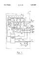
- FIG.is a diagrammatic depiction of an illustrative embodiment of the inventive system.
- the first and second heat exchangersare denoted 20 and 30, respectively, the jet pump and the compressor are denoted 40 and 50, respectively, and the control means is denoted 60.
- chiller pressurization system 10includes a special non-collapsible hose 12 that delivers cold water from the evaporator circuit of a chiller water loop, not shown, to first heat exchanger 20 through pressure switch 14 and jet pump 40.
- the function of pressure switch 14, hereinafter referred to as the first pressure switchis to detect the presence of water; when the presence of water is detected, a time circuit that controls operation of jet pump 40 and compressor 50 is started.
- line 16interconnects first pressure switch 14 and control means 60
- line 18interconnects said control means 60 and compressor 50.
- Line 22interconnects control means 60 and jet pump 40. In this manner, jet pump 40 and compressor 50 operate only when water is extracted from said evaporator circuit of the chiller water loop.
- Jet pump 40is a high speed, high pressure pump capable of pumping high volumes of water in the substantial absence of cavitation. More particularly, the pump is rated at thirty five to sixty pounds per square inch, thirty five to sixty five gallons per minute. Accordingly, water is discharged from pump 40 at 35-60 psi and at a rate of 35-60 gpm into conduit 24.
- First temperature gauge 26monitors the temperature of the water flowing through conduit 24. Line 27 interconnects temperature gauge 26 and control means 60; when the temperature of the water in conduit 24 exceeds a predetermined temperature, control means 60 deactivates the system. Temperature gauge 26 is also visually monitored. The water in conduit 24 then enters first heat exchanger 20 at first inlet 28.
- Heat exchanger 20is of the tube-in-tube type; one of the tubes carries the water from conduit 24, and the other tube carries refrigerant fluid, preferably rated R-22.
- the refrigerant fluidis delivered to the second inlet 32 of heat exchanger 20 by conduit 34 which is in fluid communication with the high pressure side of compressor 50.
- the refrigerant fluid entering first heat exchanger 20 at second inlet 32is at a high temperature and has the capacity to rapidly heat the cold chiller water.
- compressor 50discharges hot compressed gas at a temperature and pressure range that extends from about one hundred ten degrees Fahrenheit and two hundred twenty five psi to about one hundred fifty degrees and three hundred seventy five psi.
- Second pressure switch 36 at the discharge outlet of compressor 50is connected to control means 60 by line 38 and ensures that the pressures of the hot gas stay within said range. Unacceptably high pressures at second pressure switch 36 result in system shutdown by control means 60.
- the waterflows through first heat exchanger as does the hot refrigerant fluid, at a very high rate of speed.
- the refrigerant fluidflows in a first direction away from compressor 50 and the water flows in an opposite direction.
- the dwell time for the heat exchangeis of short duration, but it has been found that the very high temperature of the hot refrigerant raises the temperature of the cold water very rapidly.
- heated water returning to the evaporator circuit of a chiller water loop through conduit 44will pressurize even the largest chiller in less than an hour; the earlier techniques require about eight hours to achieve the needed pressurization.
- the heat exchange process that occurs in heat exchanger 20condenses the refrigerant. To return it to its vapor state so that it may be returned to the suction side of compressor 50, the condensed refrigerant exits first heat exchanger 20 at second outlet 46 and is delivered by conduit 48 to the second inlet 52 of second heat exchanger 30 for heating.
- the refrigerant fluidis first dried by dryer means 54. After drying, the fluid flows through expansion valve 56 which meters the refrigerant into said second heat exchanger. Unheated tap water enters second heat exchanger 30 at first inlet 58 thereof from the opposite direction through conduit 62; after the heat exchange, the cooled tap water exits first outlet 64 of heat exchanger 30 and is drained through conduit 66.
- the heat exchangeextracts heat from the water and warms the refrigerant and returns it to its vapor state; the vapor exits second heat exchanger 30 at second outlet 68 and flows through conduit 72 to suction accumulator 74 and from said accumulator to compressor 50 through conduit 76. Suction accumulator 74 protects compressor 50 from slugging. Note also third pressure switch 78 in conduit 72; it is electrically connected to control means 60 through line 82 and shuts down the system if the pressure therein drops below a predetermined threshold.
- conduit 84 at the lower right hand corner of the Figuredelivers a small quantity of the chiller gas to an adjustable pressure switch 86 and a second temperature gauge 88 is in fluid communication with conduit 84 through conduit 92.
- a signalis sent from pressure switch 86 or second temperature gauge 88 to control means 60 over line 94 and said control means shuts down the system.
- Pressure switch 86thus provides both a safety feature and an autocycle feature; the autocycle feature allows the unit to maintain proper temperatures and pressures.
- Adjustment knob 96 of pressure switch 86enables the system operator to set the pressure to which the interior of the chiller will be raised; in a preferred embodiment, the operator may set the pressure at any point between thirty inches of vacuum and ten pounds per square inch by rotating adjustment knob 96.
- the present apparatusaccomplishes the same feat in less than an hour even for the largest of chillers.
Landscapes
- Engineering & Computer Science (AREA)
- Physics & Mathematics (AREA)
- Thermal Sciences (AREA)
- Mechanical Engineering (AREA)
- General Engineering & Computer Science (AREA)
- Chemical & Material Sciences (AREA)
- Combustion & Propulsion (AREA)
- Other Air-Conditioning Systems (AREA)
Abstract
Description
Claims (12)
Priority Applications (1)
| Application Number | Priority Date | Filing Date | Title |
|---|---|---|---|
| US08/182,880US5367885A (en) | 1994-01-18 | 1994-01-18 | Chiller pressurization system |
Applications Claiming Priority (1)
| Application Number | Priority Date | Filing Date | Title |
|---|---|---|---|
| US08/182,880US5367885A (en) | 1994-01-18 | 1994-01-18 | Chiller pressurization system |
Publications (1)
| Publication Number | Publication Date |
|---|---|
| US5367885Atrue US5367885A (en) | 1994-11-29 |
Family
ID=22670452
Family Applications (1)
| Application Number | Title | Priority Date | Filing Date |
|---|---|---|---|
| US08/182,880Expired - LifetimeUS5367885A (en) | 1994-01-18 | 1994-01-18 | Chiller pressurization system |
Country Status (1)
| Country | Link |
|---|---|
| US (1) | US5367885A (en) |
Cited By (7)
| Publication number | Priority date | Publication date | Assignee | Title |
|---|---|---|---|---|
| US20040003914A1 (en)* | 2002-07-02 | 2004-01-08 | Carrier Corporation | Leak detection with thermal imaging |
| US6779350B2 (en) | 2002-03-21 | 2004-08-24 | Ritchie Enginerring Company, Inc. | Compressor head, internal discriminator, external discriminator, manifold design for refrigerant recovery apparatus and vacuum sensor |
| US6832491B2 (en) | 2002-03-21 | 2004-12-21 | Ritchie Engineering Company, Inc. | Compressor head, internal discriminator, external discriminator, manifold design for refrigerant recovery apparatus |
| US20060191276A1 (en)* | 2005-02-28 | 2006-08-31 | Carrier Corporation | Transcritical heat pump water heater with drainage |
| KR100757580B1 (en) | 2005-04-12 | 2007-09-10 | 룽-탄 후 | air-condition heat pump |
| US20100147005A1 (en)* | 2008-12-12 | 2010-06-17 | Watson Eric K | Method and apparatus for coolant control within refrigerators |
| US8301359B1 (en) | 2010-03-19 | 2012-10-30 | HyCogen Power, LLC | Microprocessor controlled automated mixing system, cogeneration system and adaptive/predictive control for use therewith |
Citations (2)
| Publication number | Priority date | Publication date | Assignee | Title |
|---|---|---|---|---|
| US4584845A (en)* | 1985-07-01 | 1986-04-29 | Borg-Warner Air Conditioning, Inc. | Control system for liquid chilled by an evaporator |
| US4856578A (en)* | 1988-04-26 | 1989-08-15 | Nepco, Inc. | Multi-function self-contained heat pump system |
- 1994
- 1994-01-18USUS08/182,880patent/US5367885A/ennot_activeExpired - Lifetime
Patent Citations (2)
| Publication number | Priority date | Publication date | Assignee | Title |
|---|---|---|---|---|
| US4584845A (en)* | 1985-07-01 | 1986-04-29 | Borg-Warner Air Conditioning, Inc. | Control system for liquid chilled by an evaporator |
| US4856578A (en)* | 1988-04-26 | 1989-08-15 | Nepco, Inc. | Multi-function self-contained heat pump system |
Cited By (16)
| Publication number | Priority date | Publication date | Assignee | Title |
|---|---|---|---|---|
| US6779350B2 (en) | 2002-03-21 | 2004-08-24 | Ritchie Enginerring Company, Inc. | Compressor head, internal discriminator, external discriminator, manifold design for refrigerant recovery apparatus and vacuum sensor |
| US6832491B2 (en) | 2002-03-21 | 2004-12-21 | Ritchie Engineering Company, Inc. | Compressor head, internal discriminator, external discriminator, manifold design for refrigerant recovery apparatus |
| US7073346B2 (en) | 2002-03-21 | 2006-07-11 | Ritchie Engineering Company, Inc. | Compressor head, internal discriminator, external discriminator, manifold design for refrigerant recovery apparatus and vacuum sensor |
| US7159412B2 (en) | 2002-03-21 | 2007-01-09 | Ritchie Engineering Company, Inc. | Compressor head, internal discriminator, external discriminator, manifold design for refrigeration recovery apparatus |
| US7428822B2 (en) | 2002-03-21 | 2008-09-30 | Ritchie Engineering Company, Inc. | Vacuum sensor |
| US7310965B2 (en) | 2002-03-21 | 2007-12-25 | Ritchie Engineering Company, Inc. | Compressor head, internal discriminator, external discriminator, manifold design for refrigeration recovery apparatus |
| US6866089B2 (en)* | 2002-07-02 | 2005-03-15 | Carrier Corporation | Leak detection with thermal imaging |
| US20040003914A1 (en)* | 2002-07-02 | 2004-01-08 | Carrier Corporation | Leak detection with thermal imaging |
| US7310960B2 (en)* | 2005-02-28 | 2007-12-25 | Carrier Corporation | Transcritical heat pump water heater with drainage |
| US20060191276A1 (en)* | 2005-02-28 | 2006-08-31 | Carrier Corporation | Transcritical heat pump water heater with drainage |
| KR100757592B1 (en) | 2005-04-12 | 2007-09-10 | 룽-탄 후 | air-condition heat pump |
| KR100757580B1 (en) | 2005-04-12 | 2007-09-10 | 룽-탄 후 | air-condition heat pump |
| US20100147005A1 (en)* | 2008-12-12 | 2010-06-17 | Watson Eric K | Method and apparatus for coolant control within refrigerators |
| US8256234B2 (en)* | 2008-12-12 | 2012-09-04 | General Electric Company | Method and apparatus for coolant control within refrigerators |
| US8301359B1 (en) | 2010-03-19 | 2012-10-30 | HyCogen Power, LLC | Microprocessor controlled automated mixing system, cogeneration system and adaptive/predictive control for use therewith |
| US8583350B1 (en) | 2010-03-19 | 2013-11-12 | HyCogen Power, LLC | Microprocessor controlled automated mixing system, cogeneration system and adaptive/predictive control for use therewith |
Similar Documents
| Publication | Publication Date | Title |
|---|---|---|
| US4903499A (en) | Refrigerant recovery system | |
| EP1982127B1 (en) | Flow control of refrigerant | |
| US5377499A (en) | Method and apparatus for refrigerant reclamation | |
| US5123259A (en) | Refrigerant recovery system | |
| US6434953B2 (en) | Filling device for motor vehicle air-conditioning systems | |
| US5367885A (en) | Chiller pressurization system | |
| US11821666B2 (en) | Refrigeration system with transfer system | |
| US4862698A (en) | Method and apparatus for testing for refrigerant leaks | |
| DE4413130A1 (en) | Cooling device for switch cabinet or other electronic equipment housing | |
| US4253312A (en) | Apparatus for the recovery of useful heat from refrigeration gases | |
| USRE35235E (en) | Method and apparatus for controlling refrigerant gas in a low pressure refrigeration system | |
| US5189882A (en) | Refrigerant recovery method | |
| US5142876A (en) | Method and apparatus for heating refrigerant in a chiller | |
| US4683724A (en) | Refrigeration moisture eliminating device and method | |
| Brownell et al. | Refrigeration system malfunctions | |
| NO170652B (en) | PROCEDURE AND DEVICE FOR PUMPING, REFERENCE TO A REFRIGERANT | |
| KR101740920B1 (en) | temperature controlling system for explosion-proof type of control panel | |
| KR20160103441A (en) | temperature controlling system for explosion-proof type of control panel | |
| EP0421999A4 (en) | Refrigerant recovery system | |
| WO2025216740A1 (en) | Portable subcooler for refrigerant recovery and method | |
| KR20250139611A (en) | Performance test system for refrigeration equipment with low-temperature heat source supply structure for water heat source/geothermal source test device | |
| KR19980044158U (en) | Thermostat | |
| JPH06265172A (en) | Air-conditioning system | |
| JPH05157415A (en) | Detecting device for abnormality of absorption refrigerating machine | |
| JPH08219597A (en) | Leaked refrigerant recovery apparatus |
Legal Events
| Date | Code | Title | Description |
|---|---|---|---|
| STCF | Information on status: patent grant | Free format text:PATENTED CASE | |
| AS | Assignment | Owner name:SONIC ENVIRONMENTAL CONTROLS, INC., NEW JERSEY Free format text:ASSIGNMENT OF ASSIGNORS INTEREST;ASSIGNOR:SAGAR, CHRISTOPHER L.;REEL/FRAME:007757/0175 Effective date:19951109 | |
| AS | Assignment | Owner name:NATWEST BANK N.A., NEW JERSEY Free format text:SECURITY INTEREST;ASSIGNOR:SONI ENVIRONMENTAL CONTROLS, INC.;REEL/FRAME:007764/0441 Effective date:19951110 | |
| AS | Assignment | Owner name:TURBOTAK TECHNOLOGIES, INC., CANADA Free format text:ASSIGNMENT OF ASSIGNORS INTEREST;ASSIGNOR:FLEET BANK, N.A.;REEL/FRAME:008167/0882 Effective date:19960926 | |
| AS | Assignment | Owner name:REFTEC INTERNATIONAL, INC., FLORIDA Free format text:ASSIGNMENT OF ASSIGNORS INTEREST;ASSIGNOR:SONIC ENVIROMENTAL CONTROLS, INC.;REEL/FRAME:008723/0255 Effective date:19970422 | |
| REMI | Maintenance fee reminder mailed | ||
| FPAY | Fee payment | Year of fee payment:4 | |
| SULP | Surcharge for late payment | ||
| FPAY | Fee payment | Year of fee payment:8 | |
| REMI | Maintenance fee reminder mailed | ||
| FPAY | Fee payment | Year of fee payment:12 | |
| SULP | Surcharge for late payment | Year of fee payment:11 | |
| AS | Assignment | Owner name:TURBOSONIC INC., CANADA Free format text:MERGER;ASSIGNOR:TURBOTAK TECHNOLOGIES, INC.;REEL/FRAME:030922/0556 Effective date:20000630 Owner name:MEGTEC TURBOSONIC INC., DELAWARE Free format text:CHANGE OF NAME;ASSIGNOR:TURBOSONIC INC.;REEL/FRAME:030937/0132 Effective date:20130131 |