US5367282A - Electric motor protector sensor - Google Patents
Electric motor protector sensorDownload PDFInfo
- Publication number
- US5367282A US5367282AUS07/918,712US91871292AUS5367282AUS 5367282 AUS5367282 AUS 5367282AUS 91871292 AUS91871292 AUS 91871292AUS 5367282 AUS5367282 AUS 5367282A
- Authority
- US
- United States
- Prior art keywords
- thermistor
- sensor
- lead members
- covering
- electrically insulating
- Prior art date
- Legal status (The legal status is an assumption and is not a legal conclusion. Google has not performed a legal analysis and makes no representation as to the accuracy of the status listed.)
- Expired - Lifetime
Links
- 230000001012protectorEffects0.000titleabstractdescription13
- 229920001971elastomerPolymers0.000claimsdescription14
- 239000000806elastomerSubstances0.000claimsdescription14
- 239000000463materialSubstances0.000claimsdescription13
- 239000012777electrically insulating materialSubstances0.000claimsdescription10
- 238000004804windingMethods0.000claimsdescription10
- 239000000853adhesiveSubstances0.000claimsdescription9
- 230000001070adhesive effectEffects0.000claimsdescription9
- KRHYYFGTRYWZRS-UHFFFAOYSA-MFluoride anionChemical compound[F-]KRHYYFGTRYWZRS-UHFFFAOYSA-M0.000claimsdescription2
- 229920006122polyamide resinPolymers0.000claimsdescription2
- -1polyethylene tetraphthalatePolymers0.000claimsdescription2
- 230000005855radiationEffects0.000claimsdescription2
- BFKJFAAPBSQJPD-UHFFFAOYSA-NtetrafluoroetheneChemical groupFC(F)=C(F)FBFKJFAAPBSQJPD-UHFFFAOYSA-N0.000claimsdescription2
- 238000003780insertionMethods0.000claims1
- 230000037431insertionEffects0.000claims1
- WABPQHHGFIMREM-UHFFFAOYSA-Nlead(0)Chemical compound[Pb]WABPQHHGFIMREM-UHFFFAOYSA-N0.000abstractdescription5
- 229920002379silicone rubberPolymers0.000abstractdescription5
- 238000000926separation methodMethods0.000abstract1
- RYGMFSIKBFXOCR-UHFFFAOYSA-NCopperChemical compound[Cu]RYGMFSIKBFXOCR-UHFFFAOYSA-N0.000description8
- 239000011889copper foilSubstances0.000description7
- 230000004044responseEffects0.000description4
- 230000008859changeEffects0.000description3
- 239000011810insulating materialSubstances0.000description3
- BQCIDUSAKPWEOX-UHFFFAOYSA-N1,1-DifluoroetheneChemical compoundFC(F)=CBQCIDUSAKPWEOX-UHFFFAOYSA-N0.000description2
- 229920006370KynarPolymers0.000description2
- 239000004809TeflonSubstances0.000description2
- 229920006362Teflon®Polymers0.000description2
- 229910002113barium titanateInorganic materials0.000description2
- JRPBQTZRNDNNOP-UHFFFAOYSA-Nbarium titanateChemical compound[Ba+2].[Ba+2].[O-][Ti]([O-])([O-])[O-]JRPBQTZRNDNNOP-UHFFFAOYSA-N0.000description2
- 230000008901benefitEffects0.000description2
- 239000000919ceramicSubstances0.000description2
- 239000011248coating agentSubstances0.000description2
- 238000000576coating methodMethods0.000description2
- 238000012986modificationMethods0.000description2
- 230000004048modificationEffects0.000description2
- 238000013021overheatingMethods0.000description2
- 239000008188pelletSubstances0.000description2
- 230000035939shockEffects0.000description2
- 229910000679solderInorganic materials0.000description2
- 229920002799BoPETPolymers0.000description1
- 239000005041Mylar™Substances0.000description1
- ATJFFYVFTNAWJD-UHFFFAOYSA-NTinChemical compound[Sn]ATJFFYVFTNAWJD-UHFFFAOYSA-N0.000description1
- 230000002411adverseEffects0.000description1
- 150000001338aliphatic hydrocarbonsChemical class0.000description1
- DUPIXUINLCPYLU-UHFFFAOYSA-Nbarium leadChemical compound[Ba].[Pb]DUPIXUINLCPYLU-UHFFFAOYSA-N0.000description1
- 229910052454barium strontium titanateInorganic materials0.000description1
- 230000004888barrier functionEffects0.000description1
- 239000004020conductorSubstances0.000description1
- 238000010276constructionMethods0.000description1
- 229910052802copperInorganic materials0.000description1
- 239000010949copperSubstances0.000description1
- 230000000694effectsEffects0.000description1
- JVPLOXQKFGYFMN-UHFFFAOYSA-Ngold tinChemical compound[Sn].[Au]JVPLOXQKFGYFMN-UHFFFAOYSA-N0.000description1
- 238000010438heat treatmentMethods0.000description1
- 238000009434installationMethods0.000description1
- 229910052746lanthanumInorganic materials0.000description1
- FZLIPJUXYLNCLC-UHFFFAOYSA-Nlanthanum atomChemical compound[La]FZLIPJUXYLNCLC-UHFFFAOYSA-N0.000description1
- LQBJWKCYZGMFEV-UHFFFAOYSA-Nlead tinChemical compound[Sn].[Pb]LQBJWKCYZGMFEV-UHFFFAOYSA-N0.000description1
- 238000004519manufacturing processMethods0.000description1
- 229920003223poly(pyromellitimide-1,4-diphenyl ether)Polymers0.000description1
- 230000000630rising effectEffects0.000description1
- 238000007789sealingMethods0.000description1
- 229910052709silverInorganic materials0.000description1
- 239000004332silverSubstances0.000description1
Images
Classifications
- H—ELECTRICITY
- H01—ELECTRIC ELEMENTS
- H01C—RESISTORS
- H01C1/00—Details
- H01C1/02—Housing; Enclosing; Embedding; Filling the housing or enclosure
- H01C1/028—Housing; Enclosing; Embedding; Filling the housing or enclosure the resistive element being embedded in insulation with outer enclosing sheath
- G—PHYSICS
- G01—MEASURING; TESTING
- G01K—MEASURING TEMPERATURE; MEASURING QUANTITY OF HEAT; THERMALLY-SENSITIVE ELEMENTS NOT OTHERWISE PROVIDED FOR
- G01K1/00—Details of thermometers not specially adapted for particular types of thermometer
- G01K1/08—Protective devices, e.g. casings
- G—PHYSICS
- G01—MEASURING; TESTING
- G01K—MEASURING TEMPERATURE; MEASURING QUANTITY OF HEAT; THERMALLY-SENSITIVE ELEMENTS NOT OTHERWISE PROVIDED FOR
- G01K7/00—Measuring temperature based on the use of electric or magnetic elements directly sensitive to heat ; Power supply therefor, e.g. using thermoelectric elements
- G01K7/16—Measuring temperature based on the use of electric or magnetic elements directly sensitive to heat ; Power supply therefor, e.g. using thermoelectric elements using resistive elements
- G01K7/22—Measuring temperature based on the use of electric or magnetic elements directly sensitive to heat ; Power supply therefor, e.g. using thermoelectric elements using resistive elements the element being a non-linear resistance, e.g. thermistor
- H—ELECTRICITY
- H02—GENERATION; CONVERSION OR DISTRIBUTION OF ELECTRIC POWER
- H02K—DYNAMO-ELECTRIC MACHINES
- H02K11/00—Structural association of dynamo-electric machines with electric components or with devices for shielding, monitoring or protection
- H02K11/20—Structural association of dynamo-electric machines with electric components or with devices for shielding, monitoring or protection for measuring, monitoring, testing, protecting or switching
- H02K11/25—Devices for sensing temperature, or actuated thereby
Definitions
- This inventionrelates to an electric motor protector sensor, and more particularly, an electric motor protector sensor positioned in the motor windings of a sealed compressor motor.
- the copper foilsnot only serve as heat-collecting members but also serve as electrical leads extending from the thermistor.
- the heat-collecting copper foilsreadily conform to the winding configuration and cooperate with low thermal inertia of the thermistor to permit very rapid response of the sensor to rising motor temperatures thereby providing desired motor protection.
- Such sensorsare described in U.S. Pat. Nos. 3,521,212 and 3,646,494 filed Jun. 21, 1968 and Jan. 23, 1970 respectively assigned to assignor of the instant application and incorporated herein by reference.
- an electric motor protector sensor of the present inventioncomprises a small thermistor of low thermal inertia contained in a high temperature covering member in which insulated electrical wire leads are connected to opposite sides of the thermistor and extend out of the cover member to an electrical circuit to connect the thermistor to the electrical circuit.
- An electrically insulating, thermally conductive elastomeris positioned around the thermistor and ends of the lead wires within the covering member to help absorb forces received by the sensor thereby protecting the integrity of the thermistor itself and the electrical contact between the lead wires and the thermistor.
- an electrical motor protector sensorcomprising a small thermistor of low thermal inertia contained in a high temperature covering member in which insulated electrical wire leads are connected to opposite sides of the thermistor and extend out of the cover member to an electrical circuit to connect the thermistor to the electrical current.
- the wire leads extending from the coveringare twisted around each other and a second high temperature covering with adhesive is formed around them to greatly improve the ability of the sensor to withstand lead wire pull-out.
- an electrically insulating, thermally conductive elastomeris positioned around the thermistor and ends of the lead wires within the covering member to help absorb forces received by the sensor thereby protecting the integrity of the thermistor itself and the electrical contact between the lead wires and the thermistor.
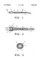
- FIG. 1is a plane view of the sensor of this invention
- FIG. 2is a section view along line 2--2 of FIG. 1;
- FIG. 3is a diagrammatic view illustrating use of the sensor within a motor winding.
- FIGS. 1 and 2indicate the novel and improved electric motor protection sensor of this invention which is shown to include a thermistor 12 which preferably comprises a small pellet of semiconductive material having a selective positive or negative temperature coefficient of resistance.
- the thermistoris adapted to display gradually changing electrical resistance in response to change of thermistor temperature within a selected range and is then adapted to display a much more rapid change in electrical resistance in response to further change of temperature.
- the thermistorembodies a lanthanum/yttrium-doped barium titanate, barium strontium titanate, barium lead titanate or the like.
- the size of the thermistoris preferably very small so that the thermistor displays low thermal inertia but the size of the thermistor in the sensor can vary within the scope of this invention in accordance with the electrical parameters of the motor control system in which the sensor is to be used.
- a practical thermistor useful in sensors finding wide commercial applicationcomprises a pellet of lanthanide-doped barium titanate 0.050 inches in length and 0.070 inches in diameter.
- thermistorsof the same material ranging in length from 0.020 to 0.060 inches and ranging in diameter from 0.050 to 0.080 inches are also useful in many applications.
- ceramic thermistorsare brittle and cannot withstand large impact forces.
- the thermistor 12is held in a covering member 14 which typically is a sleeve or tubular member of electrically insulating material.
- a covering member 14typically is a sleeve or tubular member of electrically insulating material.
- This materialis capable of withstanding substantially elevated temperatures to which the material might be exposed in an overheating electric motor.
- preferred insulating material for this purposeis a flexible radiation cross-linked polyvinylidine fluoride such as sold commercially under the tradename "Kynar”.
- Other materials useful in insulating covering 14include a polyamide resin sold under the tradename "Kapton”, a polyethylene tetraphthalate sold under the tradename "Mylar”, or a fluorinated aliphatic hydrocarbon such as tetrafluoroethylene sold under the trademark "Teflon”.
- the thin covering or tube member of the sensortypically has a thickness of in the range of 0.006 to 0.020 of an inch and the tubing is heat shrinkable for
- opposite top and bottom surfaces 16 and 18 respectively of the thermistor 12have elongated leads 20 electrically connected respectively to them for supplying electrical current to the thermistor sensor as part of a motor protection circuit, as for example, as described in U.S. Pat. No. 4,281,358 incorporated herein by reference.
- the leads 20comprise silver or tin-plated copper wires covered with Teflon and are soldered to the thermistor surface with pure tin, lead-tin or gold-tin solder material.
- thermistor 12 and the end portion of elongated leads 20are surrounded in the thin tubular covering with flexible energy absorbing coating material 22 made from a cured elastomer such as a thermally conductive, electrically insulating silicone elastomer.
- a cured elastomersuch as a thermally conductive, electrically insulating silicone elastomer.
- the elastomermust be flexible enough to distribute forces uniformly across the ceramic surface and also absorb impact energy which would otherwise be transferred directly to the brittle thermistor element. Further, the elastomer must have high thermal conductivity so as to allow the sensor to maintain appropriate fast thermal response during motor overheating. Typical properties of such material are:
- a specific example of such a materialis a Dow Corning thermally conductive silicone elastomer member Q3-6605.
- This flexible energy absorbing coating 22greatly protects the thermistor against damage due to external mechanical forces, especially present during assembly and installation of the motor and housing.
- a second sleeve or tube 24is provided adjacent covering member 14.
- the sleeve 24is preferably separate from covering member 14 and is of a flexible electrically insulating material with an adhesive lining.
- An example of suitable materialis heat shrinkable KYNAR with adhesive on the inner diameter of the sleeve.
- the leads 20are preferably twisted several times as shown in FIG. 2 prior to applying the sleeve 24 which creates helical crevices into which the adhesive can flow during the heat shrinking of the sleeve. This second sleeve after being heat shrunk around the leads 20 greatly increases the ability of the sensor device to withstand lead pull-out.
- the two elongated leads 20have one respective distal end soldered to either top or bottom surface of thermistor 12.
- the leadsfurther are twisted one around the other near the end of the leads attached to the thermistor top and bottom surfaces.
- a second sleeve 24is positioned over at least a portion of the twisted leads.
- Thermally conductive electrically insulating silicone elastomeris then positioned around the thermistor and attached leads, and then the covering sleeve 14 is placed over the thermistor with a portion of the covering extending past the end of the thermistor. This entire package is then heated to cure the silicone elastomer and to heat shrink the first sleeve and the second sleeve with adhesive.
- the heating temperature for the material described aboveshould be approximately 180° C. which is below the standard melt temperature for the solder used to attached lead wires to the thermistor.
- the resulting sensorhas the two sleeves heat shrunk to seal the end of the leads, the elastomer material and the thermistor element.
- This rugged sensoris then positioned within the insulated convolutions 30 of a motor winding 32 as shown in FIG. 3. That is, because the sensor is thin and flexible, the sensor interleaves readily between insulated convolutions 30 of the motor windings 32 to be able to accurately respond to the temperature of the windings.
- the sensor of the present inventionhas an additional advantage that, should the sensor be used in a pressurized environment, the sensor is not adversely effected by temporary loss of pressure conditions in the environment. That is, if pressurized gas from the sensor environment should enter the insulating cover of the sensor despite its generally sealed nature, the cured elastomer forms another protection barrier to protect the bond of the leads to the thermistor so as not to be effected by pressurization cycles. In this way, it is found that the sensor 10 of this invention is especially adapted for use in pressurized environments.
Landscapes
- Physics & Mathematics (AREA)
- Engineering & Computer Science (AREA)
- General Physics & Mathematics (AREA)
- Microelectronics & Electronic Packaging (AREA)
- Nonlinear Science (AREA)
- Power Engineering (AREA)
- Thermistors And Varistors (AREA)
- Measuring Temperature Or Quantity Of Heat (AREA)
Abstract
Description
Claims (14)
Priority Applications (5)
| Application Number | Priority Date | Filing Date | Title |
|---|---|---|---|
| US07/918,712US5367282A (en) | 1992-07-21 | 1992-07-21 | Electric motor protector sensor |
| JP5132097AJPH0666645A (en) | 1992-07-21 | 1993-06-02 | Sensor for motor protecting device |
| DE69323126TDE69323126T2 (en) | 1992-07-21 | 1993-07-07 | Protection sensor for electric motor |
| EP93305338AEP0580323B1 (en) | 1992-07-21 | 1993-07-07 | Electric motor protector sensor |
| KR1019930013419AKR100295967B1 (en) | 1992-07-21 | 1993-07-16 | Electric motor protection sensor |
Applications Claiming Priority (1)
| Application Number | Priority Date | Filing Date | Title |
|---|---|---|---|
| US07/918,712US5367282A (en) | 1992-07-21 | 1992-07-21 | Electric motor protector sensor |
Publications (1)
| Publication Number | Publication Date |
|---|---|
| US5367282Atrue US5367282A (en) | 1994-11-22 |
Family
ID=25440813
Family Applications (1)
| Application Number | Title | Priority Date | Filing Date |
|---|---|---|---|
| US07/918,712Expired - LifetimeUS5367282A (en) | 1992-07-21 | 1992-07-21 | Electric motor protector sensor |
Country Status (5)
| Country | Link |
|---|---|
| US (1) | US5367282A (en) |
| EP (1) | EP0580323B1 (en) |
| JP (1) | JPH0666645A (en) |
| KR (1) | KR100295967B1 (en) |
| DE (1) | DE69323126T2 (en) |
Cited By (47)
| Publication number | Priority date | Publication date | Assignee | Title |
|---|---|---|---|---|
| US5720556A (en)* | 1995-02-02 | 1998-02-24 | Keystone Thermometrics Corporation | Temperature sensor probe |
| US5754166A (en)* | 1995-04-27 | 1998-05-19 | Alps Electric Co., Ltd. | Coordinate input device |
| US5801332A (en)* | 1995-08-31 | 1998-09-01 | Minnesota Mining And Manufacturing Company | Elastically recoverable silicone splice cover |
| US5818043A (en)* | 1993-04-09 | 1998-10-06 | Thomson-Csf | Bolometric thermal detector |
| US5831511A (en)* | 1996-07-11 | 1998-11-03 | General Electric Co. | Resistance temperature detector assembly and method of fabricating same |
| US5959524A (en)* | 1995-11-15 | 1999-09-28 | Heraeus Electro-Nite International N.V. | Temperature sensor |
| US5999081A (en)* | 1996-11-29 | 1999-12-07 | Marchi Associates, Inc. | Shielding unique for filtering RFI and EFI interference signals from the measuring elements |
| WO2001036927A1 (en)* | 1999-11-16 | 2001-05-25 | Satchwell Control Systems Ltd. | Telescopic sensor assembly |
| US6380840B1 (en) | 1996-05-24 | 2002-04-30 | Heraeus Electro-Nite International N.V. | Temperature sensor with measuring resistor |
| US6437680B1 (en)* | 1999-06-14 | 2002-08-20 | Heraeus Electro-Nite International, N.V. | Process for manufacture of sensors, and sensor so made, particularly a temperature sensor |
| US6676290B1 (en)* | 2002-11-15 | 2004-01-13 | Hsueh-Yu Lu | Electronic clinical thermometer |
| US20040066836A1 (en)* | 2002-10-07 | 2004-04-08 | Ming-Yun Chen | Rapid respond electronic clinical thermometer |
| US20040135664A1 (en)* | 2003-01-07 | 2004-07-15 | Ngk Spark Plug Co., Ltd. | Temperature sensor |
| US20040161017A1 (en)* | 2002-10-18 | 2004-08-19 | Chang Hsiao Yi | Temperature probe and thermometer having the same |
| US20050063454A1 (en)* | 2002-01-18 | 2005-03-24 | Chu-Yih Yu | Thermometer having a disposable temperature probe |
| US20050123022A1 (en)* | 2002-10-18 | 2005-06-09 | Mesure Technology Co., Ltd. | Temperature probe and thermometer having the same |
| US20050174212A1 (en)* | 2004-02-06 | 2005-08-11 | Hiroyuki Abe | Temperature sensor |
| US7075407B1 (en)* | 1999-04-09 | 2006-07-11 | Murata Manufacturing Co., Ltd. | Temperature sensor |
| US20070194654A1 (en)* | 2006-02-22 | 2007-08-23 | Emerson Electric Co. | Protector mounting apparatus for protector mounted on the windings of a motor |
| US20080100184A1 (en)* | 2006-10-31 | 2008-05-01 | Emerson Electric Co. | Protector mounting apparatus for protector mounted adjacent the windings of a motor |
| US20080125335A1 (en)* | 2006-11-29 | 2008-05-29 | Schlumberger Technology Corporation | Oilfield Apparatus Comprising Swellable Elastomers Having Nanosensors Therein And Methods Of Using Same In Oilfield Application |
| US20100038554A1 (en)* | 2008-08-07 | 2010-02-18 | Ims Nanofabrication Ag | Compensation of dose inhomogeneity and image distortion |
| US20110180406A1 (en)* | 2010-01-25 | 2011-07-28 | Moshe Hirshberg | Temperature compensation for ion-selective electrodes |
| US20110216429A1 (en)* | 2004-09-15 | 2011-09-08 | Magna Donnelly Engineering Gmbh | Temperature sensor assembly for a vehicle |
| US20120057617A1 (en)* | 2009-03-27 | 2012-03-08 | Epcos Ag | Sensor arrangement and method for production |
| US20120225334A1 (en)* | 2011-03-02 | 2012-09-06 | Jong-Min Lee | Battery pack |
| US20130097858A1 (en)* | 2009-08-24 | 2013-04-25 | Endress + Hauser Flowtec Ag | Manufacturing Method for a Sensor of a Thermal Flow Measuring Device |
| US8511185B2 (en) | 2009-01-13 | 2013-08-20 | Lattron Co. Ltd. | Sensor device protected by a film layer and a resin layer |
| US20150078418A1 (en)* | 2013-09-13 | 2015-03-19 | Toyota Jidosha Kabushiki Kaisha | Thermistor module |
| US20150241285A1 (en)* | 2014-02-27 | 2015-08-27 | Amphenol Thermometrics, Inc. | Systems and methods for a temperature monitoring device |
| US9321340B2 (en) | 2010-12-07 | 2016-04-26 | Allison Transmission, Inc. | Battery array safety covers for energy storage system |
| US20160116347A1 (en)* | 2014-10-24 | 2016-04-28 | Watlow Electric Manufacturing Company | Rapid response sensor housing |
| US20160128390A1 (en)* | 2013-06-24 | 2016-05-12 | Kimree Hi-Tech Inc. | Electronic cigarette heat-generating device and electronic cigarette |
| EP3032714A1 (en)* | 2014-12-09 | 2016-06-15 | Siemens Aktiengesellschaft | Dynamoelectric machine with a reporting system for detecting a short circuit in the winding system |
| US20170016777A1 (en)* | 2014-03-07 | 2017-01-19 | Shibaura Electronics Co., Ltd. | Temperature sensor and temperature sensor manufacturing method |
| US20180258943A1 (en)* | 2017-03-10 | 2018-09-13 | Sunonwealth Electric Machine Industry Co., Ltd. | Temperature Sensor and a Fan with a Temperature Detecting Function |
| US20180337580A1 (en)* | 2015-11-25 | 2018-11-22 | Hitachi Automotive Systems, Ltd. | Stator for rotary electric machine and rotary electric machine |
| US10180288B2 (en)* | 2015-02-26 | 2019-01-15 | Northrop Grumman Systems Corporation | High-conductivity bonding of metal nanowire arrays |
| US20190164711A1 (en)* | 2017-11-27 | 2019-05-30 | Eaton Corporation | Electrical switching apparatus and harness assembly therefor |
| US10396632B2 (en)* | 2014-02-13 | 2019-08-27 | Toyota Jidosha Kabushiki Kaisha | Stator for rotary electric machine having integrally molded temperature sensor |
| US10488062B2 (en) | 2016-07-22 | 2019-11-26 | Ademco Inc. | Geofence plus schedule for a building controller |
| US10534331B2 (en) | 2013-12-11 | 2020-01-14 | Ademco Inc. | Building automation system with geo-fencing |
| US10895883B2 (en) | 2016-08-26 | 2021-01-19 | Ademco Inc. | HVAC controller with a temperature sensor mounted on a flex circuit |
| US11428585B2 (en)* | 2014-08-21 | 2022-08-30 | Shenzhen Minjie Electronic Technology Co., Ltd. | Heat radiation-resistant NTC temperature sensors and applications thereof |
| US20220307917A1 (en)* | 2019-12-24 | 2022-09-29 | Ohizumi Mfg. Co., Ltd. | Temperature sensor |
| CN115335204A (en)* | 2020-04-16 | 2022-11-11 | Tdk电子股份有限公司 | Sensor with injection molded housing made of liquid silicone rubber |
| US20220381620A1 (en)* | 2019-12-03 | 2022-12-01 | Nihon Kohden Corporation | Thermosensitive probe |
Families Citing this family (12)
| Publication number | Priority date | Publication date | Assignee | Title |
|---|---|---|---|---|
| US5675307A (en)* | 1995-08-29 | 1997-10-07 | Therm-O-Disc, Incorporated | PTC device with extended thickness |
| KR100457680B1 (en)* | 1997-08-20 | 2005-06-08 | 주식회사 휴비스 | Manufacturing method of suede polyester fabric with excellent antistatic property and hygroscopicity |
| DE19930719A1 (en)* | 1999-07-02 | 2001-01-04 | Ephy Mess Ges Fuer Elektro Phy | Process for increasing the high voltage strength of sensors and sensor with increased high voltage strength |
| DE19936218B4 (en) | 1999-08-04 | 2021-07-29 | Sew-Eurodrive Gmbh & Co Kg | Temperature-sensitive sensor for positioning in the stator windings of an electric motor |
| JP2002298721A (en)* | 2001-03-30 | 2002-10-11 | Mitsubishi Electric Corp | Circuit breaker |
| WO2002091397A1 (en)* | 2001-05-07 | 2002-11-14 | Epcos Ag | Ceramic component comprising an environmentally stable contact system |
| DE102007059848A1 (en)* | 2007-12-12 | 2009-06-25 | Robert Bosch Gmbh | Electrical arrangement and method for producing an electrical arrangement |
| FR2935562A1 (en)* | 2008-09-03 | 2010-03-05 | Michelin Soc Tech | Synchronous rotary electrical machine for on-board traction application of electric motor vehicle, has measuring sensor including sensitive head that is mounted nearer to junction of non-isolated conductive ends at common star point |
| DE102010031127A1 (en)* | 2010-07-08 | 2012-01-12 | Endress + Hauser Flowtec Ag | Measuring transducer of a thermal flowmeter for determining the flow of a medium through a measuring tube and method for its production |
| DE102013007331A1 (en) | 2013-04-27 | 2014-10-30 | Volkswagen Aktiengesellschaft | Electric machine and method for producing an electrical machine |
| US10317289B2 (en)* | 2014-09-10 | 2019-06-11 | Rockwell Automation Technologies, Inc. | Thermal well for transformer and methods |
| JP7440459B2 (en)* | 2021-05-19 | 2024-02-28 | 株式会社芝浦電子 | temperature sensor |
Citations (13)
| Publication number | Priority date | Publication date | Assignee | Title |
|---|---|---|---|---|
| US3085216A (en)* | 1961-03-01 | 1963-04-09 | Alto Scient Company Inc | Temperature sensor |
| US3246183A (en)* | 1962-09-12 | 1966-04-12 | Texas Instruments Inc | Electric winding protection |
| US3312108A (en)* | 1964-06-09 | 1967-04-04 | Applied Physics Lab | Temperature measuring device |
| US3441893A (en)* | 1966-12-28 | 1969-04-29 | Gen Electric | Resistance temperature detector |
| US3646494A (en)* | 1970-01-23 | 1972-02-29 | Texas Instruments Inc | Electric motor protector sensor |
| US3824328A (en)* | 1972-10-24 | 1974-07-16 | Texas Instruments Inc | Encapsulated ptc heater packages |
| US4437084A (en)* | 1981-10-09 | 1984-03-13 | Cooper Industries, Inc. | Encapsulated, waterproof temperature sensitive device and method of manufacture |
| US4445109A (en)* | 1981-02-11 | 1984-04-24 | Nippondenso Co., Ltd. | Temperature sensing device |
| US4449035A (en)* | 1981-04-07 | 1984-05-15 | Seb S. A. | Arrangement for mounting a thermistor-type temperature sensor in a metallic heating device |
| US4644316A (en)* | 1984-09-25 | 1987-02-17 | Tdk Corporation | Positive temperature coefficient thermistor device |
| US4789850A (en)* | 1987-12-07 | 1988-12-06 | Robertshaw Controls Company | Temperature sensor construction and method of making the same |
| US4841274A (en)* | 1987-12-21 | 1989-06-20 | Therm-O-Disc, Incorporated | Temperature responsive probe apparatus |
| US5058195A (en)* | 1990-06-07 | 1991-10-15 | Bunn-O-Matic Corporation | Thermistor mounting arrangement |
Family Cites Families (5)
| Publication number | Priority date | Publication date | Assignee | Title |
|---|---|---|---|---|
| US3158828A (en)* | 1963-05-07 | 1964-11-24 | Motorola Inc | Thermistor |
| US3521212A (en)* | 1968-06-21 | 1970-07-21 | Texas Instruments Inc | Electric motor protection sensor |
| GB1524014A (en)* | 1977-03-01 | 1978-09-06 | Standard Telephones Cables Ltd | Thermistors |
| JPS57182709A (en)* | 1981-05-07 | 1982-11-10 | Nippon Telegr & Teleph Corp <Ntt> | Reinforcing member for optical fiber connection part and its reinforcing method |
| GB2162686B (en)* | 1984-08-02 | 1988-05-11 | Stc Plc | Thermistors |
- 1992
- 1992-07-21USUS07/918,712patent/US5367282A/ennot_activeExpired - Lifetime
- 1993
- 1993-06-02JPJP5132097Apatent/JPH0666645A/enactivePending
- 1993-07-07EPEP93305338Apatent/EP0580323B1/ennot_activeExpired - Lifetime
- 1993-07-07DEDE69323126Tpatent/DE69323126T2/ennot_activeExpired - Fee Related
- 1993-07-16KRKR1019930013419Apatent/KR100295967B1/ennot_activeExpired - Fee Related
Patent Citations (13)
| Publication number | Priority date | Publication date | Assignee | Title |
|---|---|---|---|---|
| US3085216A (en)* | 1961-03-01 | 1963-04-09 | Alto Scient Company Inc | Temperature sensor |
| US3246183A (en)* | 1962-09-12 | 1966-04-12 | Texas Instruments Inc | Electric winding protection |
| US3312108A (en)* | 1964-06-09 | 1967-04-04 | Applied Physics Lab | Temperature measuring device |
| US3441893A (en)* | 1966-12-28 | 1969-04-29 | Gen Electric | Resistance temperature detector |
| US3646494A (en)* | 1970-01-23 | 1972-02-29 | Texas Instruments Inc | Electric motor protector sensor |
| US3824328A (en)* | 1972-10-24 | 1974-07-16 | Texas Instruments Inc | Encapsulated ptc heater packages |
| US4445109A (en)* | 1981-02-11 | 1984-04-24 | Nippondenso Co., Ltd. | Temperature sensing device |
| US4449035A (en)* | 1981-04-07 | 1984-05-15 | Seb S. A. | Arrangement for mounting a thermistor-type temperature sensor in a metallic heating device |
| US4437084A (en)* | 1981-10-09 | 1984-03-13 | Cooper Industries, Inc. | Encapsulated, waterproof temperature sensitive device and method of manufacture |
| US4644316A (en)* | 1984-09-25 | 1987-02-17 | Tdk Corporation | Positive temperature coefficient thermistor device |
| US4789850A (en)* | 1987-12-07 | 1988-12-06 | Robertshaw Controls Company | Temperature sensor construction and method of making the same |
| US4841274A (en)* | 1987-12-21 | 1989-06-20 | Therm-O-Disc, Incorporated | Temperature responsive probe apparatus |
| US5058195A (en)* | 1990-06-07 | 1991-10-15 | Bunn-O-Matic Corporation | Thermistor mounting arrangement |
Cited By (83)
| Publication number | Priority date | Publication date | Assignee | Title |
|---|---|---|---|---|
| US5818043A (en)* | 1993-04-09 | 1998-10-06 | Thomson-Csf | Bolometric thermal detector |
| US5720556A (en)* | 1995-02-02 | 1998-02-24 | Keystone Thermometrics Corporation | Temperature sensor probe |
| US5754166A (en)* | 1995-04-27 | 1998-05-19 | Alps Electric Co., Ltd. | Coordinate input device |
| US5801332A (en)* | 1995-08-31 | 1998-09-01 | Minnesota Mining And Manufacturing Company | Elastically recoverable silicone splice cover |
| US5959524A (en)* | 1995-11-15 | 1999-09-28 | Heraeus Electro-Nite International N.V. | Temperature sensor |
| US6380840B1 (en) | 1996-05-24 | 2002-04-30 | Heraeus Electro-Nite International N.V. | Temperature sensor with measuring resistor |
| US5831511A (en)* | 1996-07-11 | 1998-11-03 | General Electric Co. | Resistance temperature detector assembly and method of fabricating same |
| US5999081A (en)* | 1996-11-29 | 1999-12-07 | Marchi Associates, Inc. | Shielding unique for filtering RFI and EFI interference signals from the measuring elements |
| US7075407B1 (en)* | 1999-04-09 | 2006-07-11 | Murata Manufacturing Co., Ltd. | Temperature sensor |
| US7193498B2 (en) | 1999-04-09 | 2007-03-20 | Murata Manufacturing Co., Ltd. | Method of producing temperature sensor and mounting same to a circuit board |
| US20060208848A1 (en)* | 1999-04-09 | 2006-09-21 | Murata Manufacturing Co., Ltd. | Method of producing temperature sensor and mounting same to a circuit board |
| US6437680B1 (en)* | 1999-06-14 | 2002-08-20 | Heraeus Electro-Nite International, N.V. | Process for manufacture of sensors, and sensor so made, particularly a temperature sensor |
| WO2001036927A1 (en)* | 1999-11-16 | 2001-05-25 | Satchwell Control Systems Ltd. | Telescopic sensor assembly |
| US20050063454A1 (en)* | 2002-01-18 | 2005-03-24 | Chu-Yih Yu | Thermometer having a disposable temperature probe |
| US20040066836A1 (en)* | 2002-10-07 | 2004-04-08 | Ming-Yun Chen | Rapid respond electronic clinical thermometer |
| US6854882B2 (en)* | 2002-10-07 | 2005-02-15 | Actherm Inc. | Rapid response electronic clinical thermometer |
| US20050123022A1 (en)* | 2002-10-18 | 2005-06-09 | Mesure Technology Co., Ltd. | Temperature probe and thermometer having the same |
| US20040161017A1 (en)* | 2002-10-18 | 2004-08-19 | Chang Hsiao Yi | Temperature probe and thermometer having the same |
| US6979121B2 (en) | 2002-10-18 | 2005-12-27 | Mesure Technology, Co., Ltd. | Temperature probe and thermometer having the same |
| US6676290B1 (en)* | 2002-11-15 | 2004-01-13 | Hsueh-Yu Lu | Electronic clinical thermometer |
| US20040135664A1 (en)* | 2003-01-07 | 2004-07-15 | Ngk Spark Plug Co., Ltd. | Temperature sensor |
| US6997604B2 (en)* | 2003-01-07 | 2006-02-14 | Ngk Spark Plug Co., Ltd. | Temperature sensor |
| US20050174212A1 (en)* | 2004-02-06 | 2005-08-11 | Hiroyuki Abe | Temperature sensor |
| US9910000B2 (en) | 2004-09-15 | 2018-03-06 | Magna Mirrors Holding Gmbh | Temperature sensor system for a vehicle |
| US20110216429A1 (en)* | 2004-09-15 | 2011-09-08 | Magna Donnelly Engineering Gmbh | Temperature sensor assembly for a vehicle |
| US8794304B2 (en)* | 2004-09-15 | 2014-08-05 | Magna Donnelly Engineering Gmbh | Temperature sensor assembly for a vehicle |
| US20070194654A1 (en)* | 2006-02-22 | 2007-08-23 | Emerson Electric Co. | Protector mounting apparatus for protector mounted on the windings of a motor |
| US7535136B2 (en) | 2006-02-22 | 2009-05-19 | Emerson Electric Co. | Protector mounting apparatus for protector mounted on the windings of a motor |
| US20080100184A1 (en)* | 2006-10-31 | 2008-05-01 | Emerson Electric Co. | Protector mounting apparatus for protector mounted adjacent the windings of a motor |
| US8492943B2 (en) | 2006-10-31 | 2013-07-23 | Emerson Electric Co. | Protector mounting apparatus for protector mounted adjacent the windings of a motor |
| US20080125335A1 (en)* | 2006-11-29 | 2008-05-29 | Schlumberger Technology Corporation | Oilfield Apparatus Comprising Swellable Elastomers Having Nanosensors Therein And Methods Of Using Same In Oilfield Application |
| US7631697B2 (en) | 2006-11-29 | 2009-12-15 | Schlumberger Technology Corporation | Oilfield apparatus comprising swellable elastomers having nanosensors therein and methods of using same in oilfield application |
| US20100038554A1 (en)* | 2008-08-07 | 2010-02-18 | Ims Nanofabrication Ag | Compensation of dose inhomogeneity and image distortion |
| US8258488B2 (en)* | 2008-08-07 | 2012-09-04 | Ims Nanofabrication Ag | Compensation of dose inhomogeneity and image distortion |
| US8511185B2 (en) | 2009-01-13 | 2013-08-20 | Lattron Co. Ltd. | Sensor device protected by a film layer and a resin layer |
| US20120057617A1 (en)* | 2009-03-27 | 2012-03-08 | Epcos Ag | Sensor arrangement and method for production |
| US9086329B2 (en)* | 2009-03-27 | 2015-07-21 | Epcos Ag | Sensor arrangement and method for production |
| US9596795B2 (en)* | 2009-08-24 | 2017-03-14 | Endress + Hauser Flowtec Ag | Manufacturing method for sensor of a thermal flow measuring device |
| US20130097858A1 (en)* | 2009-08-24 | 2013-04-25 | Endress + Hauser Flowtec Ag | Manufacturing Method for a Sensor of a Thermal Flow Measuring Device |
| US8287705B2 (en)* | 2010-01-25 | 2012-10-16 | Thermo Fisher Scientific, Inc. | Temperature compensation for ion-selective electrodes |
| US20110180406A1 (en)* | 2010-01-25 | 2011-07-28 | Moshe Hirshberg | Temperature compensation for ion-selective electrodes |
| US11660952B2 (en) | 2010-12-07 | 2023-05-30 | Allison Transmission, Inc. | Energy storage system for electric vehicles |
| US9321340B2 (en) | 2010-12-07 | 2016-04-26 | Allison Transmission, Inc. | Battery array safety covers for energy storage system |
| US10994597B2 (en) | 2010-12-07 | 2021-05-04 | Allison Transmission, Inc. | Energy storage system for electric vehicles |
| US10421349B2 (en) | 2010-12-07 | 2019-09-24 | Allison Transmission, Inc. | Energy storage system for hybrid electric vehicle |
| US10322627B2 (en) | 2010-12-07 | 2019-06-18 | Allison Transmission, Inc. | Energy storage system for hybrid electric vehicle |
| US9415674B2 (en) | 2010-12-07 | 2016-08-16 | Allison Transmission, Inc. | Energy storage system for hybrid electric vehicle |
| US9452671B2 (en) | 2010-12-07 | 2016-09-27 | Allison Transmission, Inc. | Compliant tip thermistor with flexible clip for monitoring the temperature of a battery cell |
| US9269946B2 (en)* | 2011-03-02 | 2016-02-23 | Samsung Sdi Co., Ltd. | Battery pack having protection circuit module |
| US20120225334A1 (en)* | 2011-03-02 | 2012-09-06 | Jong-Min Lee | Battery pack |
| US20160128390A1 (en)* | 2013-06-24 | 2016-05-12 | Kimree Hi-Tech Inc. | Electronic cigarette heat-generating device and electronic cigarette |
| US20150078418A1 (en)* | 2013-09-13 | 2015-03-19 | Toyota Jidosha Kabushiki Kaisha | Thermistor module |
| US9772234B2 (en)* | 2013-09-13 | 2017-09-26 | Toyota Jidosha Kabushiki Kaisha | Thermistor module |
| US10768589B2 (en) | 2013-12-11 | 2020-09-08 | Ademco Inc. | Building automation system with geo-fencing |
| US10534331B2 (en) | 2013-12-11 | 2020-01-14 | Ademco Inc. | Building automation system with geo-fencing |
| US10591877B2 (en) | 2013-12-11 | 2020-03-17 | Ademco Inc. | Building automation remote control device with an in-application tour |
| US10649418B2 (en) | 2013-12-11 | 2020-05-12 | Ademco Inc. | Building automation controller with configurable audio/visual cues |
| US10712718B2 (en) | 2013-12-11 | 2020-07-14 | Ademco Inc. | Building automation remote control device with in-application messaging |
| US10396632B2 (en)* | 2014-02-13 | 2019-08-27 | Toyota Jidosha Kabushiki Kaisha | Stator for rotary electric machine having integrally molded temperature sensor |
| US20150241285A1 (en)* | 2014-02-27 | 2015-08-27 | Amphenol Thermometrics, Inc. | Systems and methods for a temperature monitoring device |
| US10156483B2 (en)* | 2014-03-07 | 2018-12-18 | Shibaura Electronics Co., Ltd. | Temperature sensor and temperature sensor manufacturing method |
| US20170016777A1 (en)* | 2014-03-07 | 2017-01-19 | Shibaura Electronics Co., Ltd. | Temperature sensor and temperature sensor manufacturing method |
| US11428585B2 (en)* | 2014-08-21 | 2022-08-30 | Shenzhen Minjie Electronic Technology Co., Ltd. | Heat radiation-resistant NTC temperature sensors and applications thereof |
| US20160116347A1 (en)* | 2014-10-24 | 2016-04-28 | Watlow Electric Manufacturing Company | Rapid response sensor housing |
| US10571343B2 (en)* | 2014-10-24 | 2020-02-25 | Watlow Electric Manufacturing Company | Rapid response sensor housing |
| US10454406B2 (en) | 2014-12-09 | 2019-10-22 | Siemens Aktiengesellschaft | Dynamo-electric machine comprising a signaling system for recognizing short circuits in the winding system |
| RU2668418C1 (en)* | 2014-12-09 | 2018-10-01 | Сименс Акциенгезелльшафт | Dynamo-electric machine having a signal system for recognizing short circuit in the winding system |
| EP3032714A1 (en)* | 2014-12-09 | 2016-06-15 | Siemens Aktiengesellschaft | Dynamoelectric machine with a reporting system for detecting a short circuit in the winding system |
| WO2016091556A1 (en)* | 2014-12-09 | 2016-06-16 | Siemens Aktiengesellschaft | Dynamo-electric machine comprising a signaling system for recognizing short circuits in the winding system |
| CN107005130B (en)* | 2014-12-09 | 2019-05-17 | 西门子公司 | Electromechanical machines with the reporting system for carrying out short-circuit identification to winding system |
| CN107005130A (en)* | 2014-12-09 | 2017-08-01 | 西门子公司 | Electromechanical machines with the reporting system that short-circuit identification is carried out to winding system |
| US10180288B2 (en)* | 2015-02-26 | 2019-01-15 | Northrop Grumman Systems Corporation | High-conductivity bonding of metal nanowire arrays |
| US10971977B2 (en)* | 2015-11-25 | 2021-04-06 | Hitachi Automotive Systems, Ltd. | Stator for rotary electric machine and rotary electric machine |
| US20180337580A1 (en)* | 2015-11-25 | 2018-11-22 | Hitachi Automotive Systems, Ltd. | Stator for rotary electric machine and rotary electric machine |
| US10488062B2 (en) | 2016-07-22 | 2019-11-26 | Ademco Inc. | Geofence plus schedule for a building controller |
| US10895883B2 (en) | 2016-08-26 | 2021-01-19 | Ademco Inc. | HVAC controller with a temperature sensor mounted on a flex circuit |
| US20180258943A1 (en)* | 2017-03-10 | 2018-09-13 | Sunonwealth Electric Machine Industry Co., Ltd. | Temperature Sensor and a Fan with a Temperature Detecting Function |
| US20190164711A1 (en)* | 2017-11-27 | 2019-05-30 | Eaton Corporation | Electrical switching apparatus and harness assembly therefor |
| US10431410B2 (en)* | 2017-11-27 | 2019-10-01 | Eaton Intelligent Power Limited | Electrical switching apparatus and harness assembly therefor |
| US20220381620A1 (en)* | 2019-12-03 | 2022-12-01 | Nihon Kohden Corporation | Thermosensitive probe |
| US20220307917A1 (en)* | 2019-12-24 | 2022-09-29 | Ohizumi Mfg. Co., Ltd. | Temperature sensor |
| US12135248B2 (en)* | 2019-12-24 | 2024-11-05 | Ohizumi Mfg. Co., Ltd. | Temperature sensor |
| CN115335204A (en)* | 2020-04-16 | 2022-11-11 | Tdk电子股份有限公司 | Sensor with injection molded housing made of liquid silicone rubber |
Also Published As
| Publication number | Publication date |
|---|---|
| EP0580323A3 (en) | 1995-07-26 |
| KR100295967B1 (en) | 2001-10-24 |
| DE69323126T2 (en) | 1999-07-01 |
| JPH0666645A (en) | 1994-03-11 |
| KR940003135A (en) | 1994-02-19 |
| DE69323126D1 (en) | 1999-03-04 |
| EP0580323B1 (en) | 1999-01-20 |
| EP0580323A2 (en) | 1994-01-26 |
Similar Documents
| Publication | Publication Date | Title |
|---|---|---|
| US5367282A (en) | Electric motor protector sensor | |
| CN109073480B (en) | Temperature sensor, sensor element, and method for manufacturing temperature sensor | |
| US3748439A (en) | Heating apparatus | |
| CA2007738C (en) | Multi-layer elastic sleeves for electric power cable joints and joints therewith | |
| US7453681B2 (en) | Metal oxide varistor with a heat protection | |
| US4085286A (en) | Heat-recoverable sealing article with self-contained heating means and method of sealing a splice therewith | |
| US7471498B2 (en) | Wound capacitor having a thermal disconnect at a hot spot | |
| US7741946B2 (en) | Metal oxide varistor with heat protection | |
| EP1489693B1 (en) | joint structure of superconducting cable and insulating spacer for connecting superconducting cable | |
| US2397568A (en) | Shockproof electrical resistor | |
| US4056840A (en) | Line protector for communications circuit | |
| US4972067A (en) | PTC heater assembly and a method of manufacturing the heater assembly | |
| US3521212A (en) | Electric motor protection sensor | |
| US3646494A (en) | Electric motor protector sensor | |
| US3213246A (en) | Protective encapsulation for electrical devices | |
| US4644316A (en) | Positive temperature coefficient thermistor device | |
| US3324441A (en) | Hermetically sealed electrical connections | |
| US3198873A (en) | Flexible conduits having electrical conductors therein | |
| JPH11108771A (en) | Thermistor temperature sensor | |
| CN101116153B (en) | Method for wrapping varistor component with electricity-insulating sheath and varistor component for lightning arrester | |
| JP2515067Y2 (en) | Thermistor temperature sensor | |
| JPH05196174A (en) | Isolated vacuum valve | |
| US2979645A (en) | High voltage semiconductor rectifier | |
| CN219104209U (en) | Temperature sensing element | |
| US11695265B2 (en) | Heat shrink component with heat spreading layer, and method of assembly a heat shrink component |
Legal Events
| Date | Code | Title | Description |
|---|---|---|---|
| AS | Assignment | Owner name:TEXAS INSTRUMENTS INCORPORATED A CORP. OF DELAWA Free format text:ASSIGNMENT OF ASSIGNORS INTEREST.;ASSIGNOR:CLEM, THOMAS A.;REEL/FRAME:006210/0670 Effective date:19920721 | |
| STCF | Information on status: patent grant | Free format text:PATENTED CASE | |
| FPAY | Fee payment | Year of fee payment:4 | |
| FPAY | Fee payment | Year of fee payment:8 | |
| FPAY | Fee payment | Year of fee payment:12 | |
| AS | Assignment | Owner name:MORGAN STANLEY & CO. INCORPORATED, NEW YORK Free format text:SECURITY AGREEMENT;ASSIGNORS:SENSATA TECHNOLOGIES, INC.;SENSATA TECHNOLOGIES FINANCE COMPANY, LLC;REEL/FRAME:017575/0533 Effective date:20060427 | |
| AS | Assignment | Owner name:SENSATA TECHNOLOGIES, INC., MASSACHUSETTS Free format text:ASSIGNMENT OF ASSIGNORS INTEREST;ASSIGNOR:TEXAS INSTRUMENTS INCORPORATED;REEL/FRAME:017870/0147 Effective date:20060427 | |
| AS | Assignment | Owner name:SENSATA TECHNOLOGIES MASSACHUSETTS, INC., MASSACHU Free format text:ASSIGNMENT OF ASSIGNORS INTEREST;ASSIGNOR:SENSATA TECHNOLOGIES, INC.;REEL/FRAME:021018/0690 Effective date:20080430 | |
| AS | Assignment | Owner name:MORGAN STANLEY & CO. INCORPORATED, NEW YORK Free format text:SECURITY AGREEMENT;ASSIGNOR:SENSATA TECHNOLOGIES MASSACHUSETTS, INC.;REEL/FRAME:021450/0563 Effective date:20080430 | |
| AS | Assignment | Owner name:SENSATA TECHNOLOGIES MASSACHUSETTS, INC., MASSACHU Free format text:RELEASE BY SECURED PARTY;ASSIGNOR:MORGAN STANLEY & CO. INCORPORATED;REEL/FRAME:026293/0352 Effective date:20110512 Owner name:SENSATA TECHNOLOGIES, INC., MASSACHUSETTS Free format text:RELEASE BY SECURED PARTY;ASSIGNOR:MORGAN STANLEY & CO. INCORPORATED;REEL/FRAME:026293/0352 Effective date:20110512 Owner name:SENSATA TECHNOLOGIES FINANCE COMPANY, LLC, MASSACH Free format text:RELEASE BY SECURED PARTY;ASSIGNOR:MORGAN STANLEY & CO. INCORPORATED;REEL/FRAME:026293/0352 Effective date:20110512 |